EP2649477B2 - Optical article comprising an antireflective coating with a low reflection both in the ultraviolet region and in the visible region - Google Patents
Optical article comprising an antireflective coating with a low reflection both in the ultraviolet region and in the visible region Download PDFInfo
- Publication number
- EP2649477B2 EP2649477B2 EP11794167.4A EP11794167A EP2649477B2 EP 2649477 B2 EP2649477 B2 EP 2649477B2 EP 11794167 A EP11794167 A EP 11794167A EP 2649477 B2 EP2649477 B2 EP 2649477B2
- Authority
- EP
- European Patent Office
- Prior art keywords
- layer
- incidence
- angle
- lens according
- reflection factor
- Prior art date
- Legal status (The legal status is an assumption and is not a legal conclusion. Google has not performed a legal analysis and makes no representation as to the accuracy of the status listed.)
- Active
Links
- 239000006117 anti-reflective coating Substances 0.000 title claims description 104
- 230000003287 optical effect Effects 0.000 title description 28
- VYPSYNLAJGMNEJ-UHFFFAOYSA-N Silicium dioxide Chemical group O=[Si]=O VYPSYNLAJGMNEJ-UHFFFAOYSA-N 0.000 claims description 88
- 239000000758 substrate Substances 0.000 claims description 64
- 238000000576 coating method Methods 0.000 claims description 58
- 239000011248 coating agent Substances 0.000 claims description 43
- 239000000377 silicon dioxide Substances 0.000 claims description 42
- 230000003595 spectral effect Effects 0.000 claims description 27
- 238000005299 abrasion Methods 0.000 claims description 26
- 239000000203 mixture Substances 0.000 claims description 25
- 229910052681 coesite Inorganic materials 0.000 claims description 14
- 229910052906 cristobalite Inorganic materials 0.000 claims description 14
- 229910052682 stishovite Inorganic materials 0.000 claims description 14
- 229910052905 tridymite Inorganic materials 0.000 claims description 14
- 229910003437 indium oxide Inorganic materials 0.000 claims description 11
- PJXISJQVUVHSOJ-UHFFFAOYSA-N indium(iii) oxide Chemical compound [O-2].[O-2].[O-2].[In+3].[In+3] PJXISJQVUVHSOJ-UHFFFAOYSA-N 0.000 claims description 11
- 229910001635 magnesium fluoride Inorganic materials 0.000 claims description 2
- 239000010410 layer Substances 0.000 description 188
- 230000005855 radiation Effects 0.000 description 21
- MCMNRKCIXSYSNV-UHFFFAOYSA-N Zirconium dioxide Chemical compound O=[Zr]=O MCMNRKCIXSYSNV-UHFFFAOYSA-N 0.000 description 20
- 230000003667 anti-reflective effect Effects 0.000 description 17
- PNEYBMLMFCGWSK-UHFFFAOYSA-N aluminium oxide Inorganic materials [O-2].[O-2].[O-2].[Al+3].[Al+3] PNEYBMLMFCGWSK-UHFFFAOYSA-N 0.000 description 14
- 239000002987 primer (paints) Substances 0.000 description 14
- 239000006120 scratch resistant coating Substances 0.000 description 13
- GWEVSGVZZGPLCZ-UHFFFAOYSA-N Titan oxide Chemical compound O=[Ti]=O GWEVSGVZZGPLCZ-UHFFFAOYSA-N 0.000 description 11
- 238000000034 method Methods 0.000 description 11
- 239000000463 material Substances 0.000 description 9
- -1 poly(methacrylate) Polymers 0.000 description 9
- XLOMVQKBTHCTTD-UHFFFAOYSA-N Zinc monoxide Chemical compound [Zn]=O XLOMVQKBTHCTTD-UHFFFAOYSA-N 0.000 description 8
- 229910052593 corundum Inorganic materials 0.000 description 8
- 229910001845 yogo sapphire Inorganic materials 0.000 description 8
- 238000000151 deposition Methods 0.000 description 7
- 238000001704 evaporation Methods 0.000 description 7
- 239000004814 polyurethane Substances 0.000 description 7
- 229920002635 polyurethane Polymers 0.000 description 7
- 229920001577 copolymer Polymers 0.000 description 6
- 230000008020 evaporation Effects 0.000 description 6
- 230000002209 hydrophobic effect Effects 0.000 description 6
- XOLBLPGZBRYERU-UHFFFAOYSA-N tin dioxide Chemical compound O=[Sn]=O XOLBLPGZBRYERU-UHFFFAOYSA-N 0.000 description 6
- OGIDPMRJRNCKJF-UHFFFAOYSA-N titanium oxide Inorganic materials [Ti]=O OGIDPMRJRNCKJF-UHFFFAOYSA-N 0.000 description 6
- JHQVCQDWGSXTFE-UHFFFAOYSA-N 2-(2-prop-2-enoxycarbonyloxyethoxy)ethyl prop-2-enyl carbonate Chemical compound C=CCOC(=O)OCCOCCOC(=O)OCC=C JHQVCQDWGSXTFE-UHFFFAOYSA-N 0.000 description 5
- XKRFYHLGVUSROY-UHFFFAOYSA-N Argon Chemical compound [Ar] XKRFYHLGVUSROY-UHFFFAOYSA-N 0.000 description 5
- 230000005540 biological transmission Effects 0.000 description 5
- 239000002243 precursor Substances 0.000 description 5
- 238000001228 spectrum Methods 0.000 description 5
- 230000003068 static effect Effects 0.000 description 5
- 235000014692 zinc oxide Nutrition 0.000 description 5
- YYLGKUPAFFKGRQ-UHFFFAOYSA-N dimethyldiethoxysilane Chemical compound CCO[Si](C)(C)OCC YYLGKUPAFFKGRQ-UHFFFAOYSA-N 0.000 description 4
- 208000028659 discharge Diseases 0.000 description 4
- 239000011521 glass Substances 0.000 description 4
- 150000002500 ions Chemical class 0.000 description 4
- PLDDOISOJJCEMH-UHFFFAOYSA-N neodymium(3+);oxygen(2-) Chemical compound [O-2].[O-2].[O-2].[Nd+3].[Nd+3] PLDDOISOJJCEMH-UHFFFAOYSA-N 0.000 description 4
- 229920000515 polycarbonate Polymers 0.000 description 4
- 239000004417 polycarbonate Substances 0.000 description 4
- 239000000126 substance Substances 0.000 description 4
- 229910001887 tin oxide Inorganic materials 0.000 description 4
- BPSIOYPQMFLKFR-UHFFFAOYSA-N trimethoxy-[3-(oxiran-2-ylmethoxy)propyl]silane Chemical compound CO[Si](OC)(OC)CCCOCC1CO1 BPSIOYPQMFLKFR-UHFFFAOYSA-N 0.000 description 4
- 239000011787 zinc oxide Substances 0.000 description 4
- KILURZWTCGSYRE-LNTINUHCSA-K (z)-4-bis[[(z)-4-oxopent-2-en-2-yl]oxy]alumanyloxypent-3-en-2-one Chemical compound CC(=O)\C=C(\C)O[Al](O\C(C)=C/C(C)=O)O\C(C)=C/C(C)=O KILURZWTCGSYRE-LNTINUHCSA-K 0.000 description 3
- NIXOWILDQLNWCW-UHFFFAOYSA-M Acrylate Chemical compound [O-]C(=O)C=C NIXOWILDQLNWCW-UHFFFAOYSA-M 0.000 description 3
- VEXZGXHMUGYJMC-UHFFFAOYSA-N Hydrochloric acid Chemical compound Cl VEXZGXHMUGYJMC-UHFFFAOYSA-N 0.000 description 3
- OKKJLVBELUTLKV-UHFFFAOYSA-N Methanol Chemical compound OC OKKJLVBELUTLKV-UHFFFAOYSA-N 0.000 description 3
- NIXOWILDQLNWCW-UHFFFAOYSA-N acrylic acid group Chemical group C(C=C)(=O)O NIXOWILDQLNWCW-UHFFFAOYSA-N 0.000 description 3
- 229910052786 argon Inorganic materials 0.000 description 3
- 239000008119 colloidal silica Substances 0.000 description 3
- 230000000052 comparative effect Effects 0.000 description 3
- 238000009826 distribution Methods 0.000 description 3
- XPBBUZJBQWWFFJ-UHFFFAOYSA-N fluorosilane Chemical compound [SiH3]F XPBBUZJBQWWFFJ-UHFFFAOYSA-N 0.000 description 3
- 238000010884 ion-beam technique Methods 0.000 description 3
- 238000004519 manufacturing process Methods 0.000 description 3
- 229910044991 metal oxide Inorganic materials 0.000 description 3
- 150000004706 metal oxides Chemical class 0.000 description 3
- BPUBBGLMJRNUCC-UHFFFAOYSA-N oxygen(2-);tantalum(5+) Chemical compound [O-2].[O-2].[O-2].[O-2].[O-2].[Ta+5].[Ta+5] BPUBBGLMJRNUCC-UHFFFAOYSA-N 0.000 description 3
- 229920000728 polyester Polymers 0.000 description 3
- 238000006116 polymerization reaction Methods 0.000 description 3
- PBCFLUZVCVVTBY-UHFFFAOYSA-N tantalum pentoxide Inorganic materials O=[Ta](=O)O[Ta](=O)=O PBCFLUZVCVVTBY-UHFFFAOYSA-N 0.000 description 3
- 238000001429 visible spectrum Methods 0.000 description 3
- VGGSQFUCUMXWEO-UHFFFAOYSA-N Ethene Chemical compound C=C VGGSQFUCUMXWEO-UHFFFAOYSA-N 0.000 description 2
- 239000005977 Ethylene Substances 0.000 description 2
- MHAJPDPJQMAIIY-UHFFFAOYSA-N Hydrogen peroxide Chemical compound OO MHAJPDPJQMAIIY-UHFFFAOYSA-N 0.000 description 2
- RTAQQCXQSZGOHL-UHFFFAOYSA-N Titanium Chemical compound [Ti] RTAQQCXQSZGOHL-UHFFFAOYSA-N 0.000 description 2
- 229920006243 acrylic copolymer Polymers 0.000 description 2
- 230000003213 activating effect Effects 0.000 description 2
- 239000003054 catalyst Substances 0.000 description 2
- 239000008199 coating composition Substances 0.000 description 2
- 150000001875 compounds Chemical class 0.000 description 2
- ZSWFCLXCOIISFI-UHFFFAOYSA-N cyclopentadiene Chemical compound C1C=CC=C1 ZSWFCLXCOIISFI-UHFFFAOYSA-N 0.000 description 2
- 230000008021 deposition Effects 0.000 description 2
- 230000001627 detrimental effect Effects 0.000 description 2
- 238000003618 dip coating Methods 0.000 description 2
- MRNHPUHPBOKKQT-UHFFFAOYSA-N indium;tin;hydrate Chemical compound O.[In].[Sn] MRNHPUHPBOKKQT-UHFFFAOYSA-N 0.000 description 2
- 230000031700 light absorption Effects 0.000 description 2
- 239000000178 monomer Substances 0.000 description 2
- ZKATWMILCYLAPD-UHFFFAOYSA-N niobium pentoxide Chemical compound O=[Nb](=O)O[Nb](=O)=O ZKATWMILCYLAPD-UHFFFAOYSA-N 0.000 description 2
- 229920002037 poly(vinyl butyral) polymer Polymers 0.000 description 2
- 229920001707 polybutylene terephthalate Polymers 0.000 description 2
- 229920000139 polyethylene terephthalate Polymers 0.000 description 2
- 239000005020 polyethylene terephthalate Substances 0.000 description 2
- 229920000642 polymer Polymers 0.000 description 2
- 229920000193 polymethacrylate Polymers 0.000 description 2
- 230000003678 scratch resistant effect Effects 0.000 description 2
- 239000002904 solvent Substances 0.000 description 2
- 238000004528 spin coating Methods 0.000 description 2
- 125000000446 sulfanediyl group Chemical group *S* 0.000 description 2
- 239000004094 surface-active agent Substances 0.000 description 2
- 229920001169 thermoplastic Polymers 0.000 description 2
- 229920001187 thermosetting polymer Polymers 0.000 description 2
- 239000004416 thermosoftening plastic Substances 0.000 description 2
- 239000010409 thin film Substances 0.000 description 2
- 239000004408 titanium dioxide Substances 0.000 description 2
- 239000012780 transparent material Substances 0.000 description 2
- XLYOFNOQVPJJNP-UHFFFAOYSA-N water Substances O XLYOFNOQVPJJNP-UHFFFAOYSA-N 0.000 description 2
- RUDFQVOCFDJEEF-UHFFFAOYSA-N yttrium(III) oxide Inorganic materials [O-2].[O-2].[O-2].[Y+3].[Y+3] RUDFQVOCFDJEEF-UHFFFAOYSA-N 0.000 description 2
- ZNQVEEAIQZEUHB-UHFFFAOYSA-N 2-ethoxyethanol Chemical compound CCOCCO ZNQVEEAIQZEUHB-UHFFFAOYSA-N 0.000 description 1
- 239000004593 Epoxy Substances 0.000 description 1
- CERQOIWHTDAKMF-UHFFFAOYSA-M Methacrylate Chemical compound CC(=C)C([O-])=O CERQOIWHTDAKMF-UHFFFAOYSA-M 0.000 description 1
- 229910052777 Praseodymium Inorganic materials 0.000 description 1
- 239000004433 Thermoplastic polyurethane Substances 0.000 description 1
- 229910003087 TiOx Inorganic materials 0.000 description 1
- ATJFFYVFTNAWJD-UHFFFAOYSA-N Tin Chemical compound [Sn] ATJFFYVFTNAWJD-UHFFFAOYSA-N 0.000 description 1
- XTXRWKRVRITETP-UHFFFAOYSA-N Vinyl acetate Chemical compound CC(=O)OC=C XTXRWKRVRITETP-UHFFFAOYSA-N 0.000 description 1
- 239000002253 acid Substances 0.000 description 1
- 230000004913 activation Effects 0.000 description 1
- 239000004411 aluminium Substances 0.000 description 1
- 229910052782 aluminium Inorganic materials 0.000 description 1
- XAGFODPZIPBFFR-UHFFFAOYSA-N aluminium Chemical compound [Al] XAGFODPZIPBFFR-UHFFFAOYSA-N 0.000 description 1
- 230000003373 anti-fouling effect Effects 0.000 description 1
- QVGXLLKOCUKJST-UHFFFAOYSA-N atomic oxygen Chemical compound [O] QVGXLLKOCUKJST-UHFFFAOYSA-N 0.000 description 1
- SFFFIHNOEGSAIH-UHFFFAOYSA-N bicyclo[2.2.1]hept-2-ene;ethene Chemical compound C=C.C1C2CCC1C=C2 SFFFIHNOEGSAIH-UHFFFAOYSA-N 0.000 description 1
- SYFOAKAXGNMQAX-UHFFFAOYSA-N bis(prop-2-enyl) carbonate;2-(2-hydroxyethoxy)ethanol Chemical compound OCCOCCO.C=CCOC(=O)OCC=C SYFOAKAXGNMQAX-UHFFFAOYSA-N 0.000 description 1
- 230000003197 catalytic effect Effects 0.000 description 1
- 239000003795 chemical substances by application Substances 0.000 description 1
- 238000005229 chemical vapour deposition Methods 0.000 description 1
- 238000004140 cleaning Methods 0.000 description 1
- 238000009833 condensation Methods 0.000 description 1
- 230000005494 condensation Effects 0.000 description 1
- 238000003851 corona treatment Methods 0.000 description 1
- 230000001419 dependent effect Effects 0.000 description 1
- 230000005670 electromagnetic radiation Effects 0.000 description 1
- 238000010894 electron beam technology Methods 0.000 description 1
- 239000004744 fabric Substances 0.000 description 1
- 210000000887 face Anatomy 0.000 description 1
- 239000012467 final product Substances 0.000 description 1
- 238000010438 heat treatment Methods 0.000 description 1
- HCDGVLDPFQMKDK-UHFFFAOYSA-N hexafluoropropylene Chemical group FC(F)=C(F)C(F)(F)F HCDGVLDPFQMKDK-UHFFFAOYSA-N 0.000 description 1
- 230000007062 hydrolysis Effects 0.000 description 1
- 238000006460 hydrolysis reaction Methods 0.000 description 1
- 229910052738 indium Inorganic materials 0.000 description 1
- APFVFJFRJDLVQX-UHFFFAOYSA-N indium atom Chemical compound [In] APFVFJFRJDLVQX-UHFFFAOYSA-N 0.000 description 1
- 229910052500 inorganic mineral Inorganic materials 0.000 description 1
- 238000001659 ion-beam spectroscopy Methods 0.000 description 1
- MRELNEQAGSRDBK-UHFFFAOYSA-N lanthanum oxide Inorganic materials [O-2].[O-2].[O-2].[La+3].[La+3] MRELNEQAGSRDBK-UHFFFAOYSA-N 0.000 description 1
- 238000005259 measurement Methods 0.000 description 1
- 230000001404 mediated effect Effects 0.000 description 1
- 125000002496 methyl group Chemical group [H]C([H])([H])* 0.000 description 1
- 239000011707 mineral Substances 0.000 description 1
- 235000010755 mineral Nutrition 0.000 description 1
- 239000012764 mineral filler Substances 0.000 description 1
- 238000006386 neutralization reaction Methods 0.000 description 1
- 239000003960 organic solvent Substances 0.000 description 1
- KTUFCUMIWABKDW-UHFFFAOYSA-N oxo(oxolanthaniooxy)lanthanum Chemical compound O=[La]O[La]=O KTUFCUMIWABKDW-UHFFFAOYSA-N 0.000 description 1
- 239000001301 oxygen Substances 0.000 description 1
- 229910052760 oxygen Inorganic materials 0.000 description 1
- MMKQUGHLEMYQSG-UHFFFAOYSA-N oxygen(2-);praseodymium(3+) Chemical compound [O-2].[O-2].[O-2].[Pr+3].[Pr+3] MMKQUGHLEMYQSG-UHFFFAOYSA-N 0.000 description 1
- 239000010702 perfluoropolyether Substances 0.000 description 1
- 238000001782 photodegradation Methods 0.000 description 1
- 238000000623 plasma-assisted chemical vapour deposition Methods 0.000 description 1
- 229920000647 polyepoxide Polymers 0.000 description 1
- 239000002861 polymer material Substances 0.000 description 1
- 229920005862 polyol Polymers 0.000 description 1
- 229920001451 polypropylene glycol Polymers 0.000 description 1
- PUDIUYLPXJFUGB-UHFFFAOYSA-N praseodymium atom Chemical compound [Pr] PUDIUYLPXJFUGB-UHFFFAOYSA-N 0.000 description 1
- 238000002203 pretreatment Methods 0.000 description 1
- 239000000047 product Substances 0.000 description 1
- 230000001737 promoting effect Effects 0.000 description 1
- 238000005086 pumping Methods 0.000 description 1
- 239000010453 quartz Substances 0.000 description 1
- 229920005989 resin Polymers 0.000 description 1
- 239000011347 resin Substances 0.000 description 1
- 210000001525 retina Anatomy 0.000 description 1
- 150000004756 silanes Chemical class 0.000 description 1
- 239000002356 single layer Substances 0.000 description 1
- 238000004544 sputter deposition Methods 0.000 description 1
- 238000010998 test method Methods 0.000 description 1
- 239000012815 thermoplastic material Substances 0.000 description 1
- 229920002803 thermoplastic polyurethane Polymers 0.000 description 1
- 229910052718 tin Inorganic materials 0.000 description 1
- HLLICFJUWSZHRJ-UHFFFAOYSA-N tioxidazole Chemical compound CCCOC1=CC=C2N=C(NC(=O)OC)SC2=C1 HLLICFJUWSZHRJ-UHFFFAOYSA-N 0.000 description 1
- 239000010936 titanium Substances 0.000 description 1
- 229910052719 titanium Inorganic materials 0.000 description 1
- 238000002211 ultraviolet spectrum Methods 0.000 description 1
- 238000001771 vacuum deposition Methods 0.000 description 1
- 238000009423 ventilation Methods 0.000 description 1
- RNWHGQJWIACOKP-UHFFFAOYSA-N zinc;oxygen(2-) Chemical class [O-2].[Zn+2] RNWHGQJWIACOKP-UHFFFAOYSA-N 0.000 description 1
Images

Classifications
-
- G—PHYSICS
- G02—OPTICS
- G02C—SPECTACLES; SUNGLASSES OR GOGGLES INSOFAR AS THEY HAVE THE SAME FEATURES AS SPECTACLES; CONTACT LENSES
- G02C7/00—Optical parts
- G02C7/02—Lenses; Lens systems ; Methods of designing lenses
- G02C7/022—Ophthalmic lenses having special refractive features achieved by special materials or material structures
-
- G—PHYSICS
- G02—OPTICS
- G02B—OPTICAL ELEMENTS, SYSTEMS OR APPARATUS
- G02B1/00—Optical elements characterised by the material of which they are made; Optical coatings for optical elements
- G02B1/10—Optical coatings produced by application to, or surface treatment of, optical elements
- G02B1/11—Anti-reflection coatings
- G02B1/113—Anti-reflection coatings using inorganic layer materials only
- G02B1/115—Multilayers
-
- G—PHYSICS
- G02—OPTICS
- G02B—OPTICAL ELEMENTS, SYSTEMS OR APPARATUS
- G02B1/00—Optical elements characterised by the material of which they are made; Optical coatings for optical elements
- G02B1/10—Optical coatings produced by application to, or surface treatment of, optical elements
- G02B1/11—Anti-reflection coatings
- G02B1/113—Anti-reflection coatings using inorganic layer materials only
- G02B1/115—Multilayers
- G02B1/116—Multilayers including electrically conducting layers
-
- G—PHYSICS
- G02—OPTICS
- G02B—OPTICAL ELEMENTS, SYSTEMS OR APPARATUS
- G02B5/00—Optical elements other than lenses
- G02B5/20—Filters
- G02B5/28—Interference filters
- G02B5/283—Interference filters designed for the ultraviolet
-
- G—PHYSICS
- G02—OPTICS
- G02C—SPECTACLES; SUNGLASSES OR GOGGLES INSOFAR AS THEY HAVE THE SAME FEATURES AS SPECTACLES; CONTACT LENSES
- G02C7/00—Optical parts
- G02C7/02—Lenses; Lens systems ; Methods of designing lenses
-
- G—PHYSICS
- G02—OPTICS
- G02C—SPECTACLES; SUNGLASSES OR GOGGLES INSOFAR AS THEY HAVE THE SAME FEATURES AS SPECTACLES; CONTACT LENSES
- G02C7/00—Optical parts
- G02C7/10—Filters, e.g. for facilitating adaptation of the eyes to the dark; Sunglasses
-
- G—PHYSICS
- G02—OPTICS
- G02C—SPECTACLES; SUNGLASSES OR GOGGLES INSOFAR AS THEY HAVE THE SAME FEATURES AS SPECTACLES; CONTACT LENSES
- G02C7/00—Optical parts
- G02C7/10—Filters, e.g. for facilitating adaptation of the eyes to the dark; Sunglasses
- G02C7/104—Filters, e.g. for facilitating adaptation of the eyes to the dark; Sunglasses having spectral characteristics for purposes other than sun-protection
-
- G—PHYSICS
- G02—OPTICS
- G02C—SPECTACLES; SUNGLASSES OR GOGGLES INSOFAR AS THEY HAVE THE SAME FEATURES AS SPECTACLES; CONTACT LENSES
- G02C2202/00—Generic optical aspects applicable to one or more of the subgroups of G02C7/00
- G02C2202/16—Laminated or compound lenses
Definitions
- the present invention relates to an optical article comprising on its rear face, and optionally on its front face, an antireflective coating which strongly reduce reflection in the UVA-and UVB-radiation range, and in the visible region.
- the optical article may especially be an ophthalmic lens, especially a tinted solar lens.
- the solar spectrum comprises electromagnetic radiations having various wavelengths, especially ultraviolet radiation (UV).
- UV ultraviolet radiation
- the UV spectrum has many bands, especially UVA, UVB and UVC bands. Amongst those UV bands which do reach the earth surface, UVA band, ranging from 315 nm to 380, and UVB band, ranging from 280 nm to 315 nm, are particularly harmful to the retina.
- Anti-reflective coatings are designed and optimized to reduce reflection on the lens surface in the visible region, typically within the spectrum range of from 380 to 780 nm. As a rule, the reflection in the ultraviolet region (280-380 nm) is not optimized, and is frequently reinforced by the traditional antireflective coating itself.
- the mean reflection in the UVA and UVB regions may thus attain high levels (up to 60%) for traditional antireflective lenses.
- the UV mean reflection does range from 10 to 25%, for an angle of incidence of from 30 to 45°. It is not problematic on the front face of the lens, since the major part of the UV radiation which comes from the front of the wearer and might attain the wearer's eye (normal incidence, 0 to 15°) generally get absorbed by the ophthalmic lens substrate.
- a better protection against UV radiation transmission may be obtained through solar ophthalmic lenses, which are studied and designed to reduce the visible spectrum luminosity, totally absorb UVB and totally or partially absorb UVA.
- the UV radiation resulting from light sources located behind the wearer may reflect on the lens rear face and reach the wearer's eye if the lens is not provided with an antireflective coating which is efficient in the ultraviolet region, thus potentially affecting the wearer's health.
- Such phenomenon is made stronger by the trend for fashion sunglasses with high diameters which increase the risk of stray reflections getting into the eyes.
- the light rays that may reflect onto the lens rear face and reach the wearer's eye have a narrow incidence angle range, ranging from 30 to 45° (oblique incidence).
- the application EP 1 174 734 discloses a spectacle lens comprising on its rear face a multilayered antireflective coating designed in such a way that the reflection on the antireflective coating surface be lower as compared to the one on the bare optical article surface within the 280-700 nm wavelength range.
- the function of this antireflective coating consists in minimizing the reflection of the UV radiation originating from behind the wearer or reflected by the wearer's face, on the lens rear face, so as to prevent the same from reaching the wearer's eye.
- the antireflective coatings described in this application are very efficient in the ultraviolet region. However, it would be advisable to improve their mean reflection factors in the visible region. Moreover, the conceived stacks are sometimes relatively sophisticated, as they may have up to 10 layers.
- the application WO 97/28467 discloses a transparent photochromic article comprising a photochromic substrate coated with a tetra-layer-antireflective stack HI/LI/HI/LI, where HI refers to a layer with a high refractive index and LI to a layer with a low refractive index.
- HI refers to a layer with a high refractive index
- LI to a layer with a low refractive index.
- Such coating is designed so as not to interfere with the behavior of the photochromic compounds that are present in or onto the substrate, by minimizing the reflection between 350 and 400 nm, which is the wavelength range enabling their activation.
- the thus prepared antireflective coatings are efficient in the UVA region, but this property is accompanied with a significant decrease in the antireflective performances in the visible region.
- the patent US 4 852 974 discloses an optical article comprising a photochromic substrate and a multilayered antireflective coating, having a mean reflection factor between 290 nm and 330 nm higher than 15% and a mean reflection factor between 330 nm and 380 nm that is lower than 4% for an angle of incidence that was not communicated.
- Such antireflective coating makes it possible to extend the life-time of the photochromic compounds contained in the substrate, but is relatively inefficient within a range where the UV radiation relative efficiency is the highest (290-300 nm). Moreover, it would be desirable to improve its performances in the visible region.
- the application WO 2010/125 667 discloses a spectacle lens provided on its rear face with an antireflective coating enabling to reduce the reflection on the lens rear face of the UV radiation originating from behind the wearer, so that it cannot reach his eye.
- the present invention provides an antireflective coating with an improved conception, comprising a stack made of thin layers, the thicknesses and materials of which have been selected so as to obtain satisfactory antireflective performances both in the visible region and in the ultraviolet region.
- the ultraviolet solar radiation distribution is tempered by the relative spectral efficiency of the UV solar radiation, which is nil or almost nil in the range of from 280 to 295 nm (which belongs to the ultraviolet B-ray region).
- the present invention provides an antireflective coating with lower antireflection performances within this wavelength region, thus allowing to obtain an antireflective coating that is very efficient in the visible region and in the part of the ultraviolet range where the solar radiation distribution tempered by the relative spectral efficiency of such radiation is high for the wearer (300-320 nm).
- the antireflective coatings according to the invention thus tolerate a higher spectral reflection in the 280 to 295 nm region, with no consequence on the wearer.
- the invention therefore relates to an ophthalmic lens, comprising all the features recited in claim 1. Additional embodiments are defined in dependent claims.
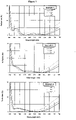
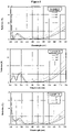
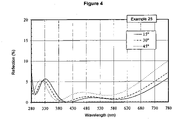
- Figures 1 to 4 show the variation as a function of the reflection wavelength on the surface of the rear face of some lenses prepared in the examples of the present application, for an angle of incidence of 15°, 30° and 45°.
- an optical article comprises one or more coatings onto the surface thereof
- the expression "to deposit a layer or a coating onto the article” is intended to mean that a layer or a coating is deposited onto the external (exposed) surface of the outer coating of the article, that is to say its coating that is the most distant from the substrate.
- a coating, that is said to be “on” a substrate or deposited “onto” a substrate is defined as a coating, which (i) is positioned above the substrate, (ii) is not necessarily in contact with the substrate, that is to say one or more intermediate coatings may be arranged between the substrate and the coating in question, and (iii) does not necessarily completely cover the substrate.
- the coating on a substrate or deposited onto a substrate is in direct contact with this substrate.
- a layer 1 is lying under a layer 2
- layer 2 is more distant from the substrate than layer 1.
- the rear (or the inner) face of the substrate is intended to mean the face which, when using the article, is the nearest from the wearer's eye. It is generally a concave face.
- the front face of the substrate is the face which, when using the article, is the most distant from the wearer's eye. It is generally a convex face.
- the antireflective coating of the optical article according to the invention may be deposited onto any substrate, and preferably onto organic lens substrates, for example a thermoplastic or thermosetting plastic material.
- Thermoplastic materials to be suitably used for the substrates include (meth)acrylic (co)polymers, especially methyl poly(methacrylate) (PMMA), thio(meth)acrylic (co)polymers, polyvinylbutyral (PVB), polycarbonates (PC), polyurethanes (PU), poly(thiourethanes), polyol allylcarbonate (co)polymers, thermoplastic copolymers of ethylene/vinyl acetate, polyesters such as polyethylene terephthalate (PET) or polybutylene terephthalate (PBT), polyepisulfides, polyepoxides, polycarbonate/polyester copolymers, cycloolefin copolymers such as copolymers of ethylene/norbornene or ethylene/cyclopentadiene, and combinations thereof.
- PMMA methyl poly(methacrylate)
- PVB polyvinylbutyral
- PC polycarbonates
- a (co)polymer is intended to mean a copolymer or a polymer.
- a (meth)acrylate is intended to mean an acrylate or a methacrylate.
- a polycarbonate is intended to mean either homopolycarbonates or copolycarbonates and block copolycarbonates.
- Particularly recommended substrates include those substrates obtained through (co)polymerization of the diethyleneglycol bis-allyl-carbonate, marketed, for example, under the trade name CR-39 ® by the PPG Industries company (ORMA ® lenses, ESSILOR), or through polymerization of the thio(meth)acrylate monomers, such as those described in the application of the French patent FR 2 734 827 .
- the substrates may be obtained through polymerization of the above monomer combinations, or may further comprise mixtures of such polymers and (co)polymers.
- the surface of said optionally coated substrate Prior to depositing the antireflective coating onto the optionally coated substrate, for example with an abrasion-resistant layer and/or a scratch-resistant coating or with a sub-layer, the surface of said optionally coated substrate is usually submitted to a physical or chemical surface activating treatment, so as to reinforce the adhesion of the antireflective coating.
- a physical or chemical surface activating treatment is generally conducted under vacuum. It may be a bombardment with energetic and/or reactive species, for example with an ion beam ("Ion Pre-Cleaning" or "IPC") or with an electron beam, a corona discharge treatment, an ion spallation treatment, an ultraviolet treatment or a plasma-mediated treatment under vacuum, generally using an oxygen or an argon plasma. It may also be an acid or basic treatment and/or a solvent-based treatment (water, hydrogen peroxide or any organic solvent).
- the "mean reflection factor,” noted R m is such as defined in the ISO 13666:1998 Standard, and measured in accordance with the ISO 8980-4 Standard (for an angle of incidence lower than 17°, typically of 15°), i.e. this is the (non weighted) spectral reflection average over the whole visible spectrum between 400 and 700 nm.
- the "mean light reflection factor,” noted R v is such as defined in the ISO 13666:1998 Standard, and measured in accordance with the ISO 8980-4 Standard (for an angle of incidence lower than 17°, typically of 15°), i.e. this is the weighted spectral reflection average over the whole visible spectrum between 380 and 780 nm.
- the mean reflection factor between 290 and 330 nm, noted R m-UV1 can be defined by analogy, which corresponds to the mean spectral reflection between 290 and 330 nm. According to the invention, this factor may be measured at an angle of incidence that may range from 30 to 45°.
- the mean reflection factors in the UVA and UVB ranges, noted R m-UVA and R m-UVB are defined, the sum of which corresponds to the mean reflection factor in the ultraviolet region (280-380 nm), noted R m-UV .
- the spectral function W( ⁇ ), enabling to calculate the ultraviolet radiation transmission factors, is defined according to the ISO 13666:1998 Standard. It makes it possible to express the ultraviolet solar radiation distribution tempered by the relative spectral efficiency of such radiation for the wearer, since it simultaneously takes both the solar spectral energy Es( ⁇ ) into account, which does globally emit less UVB-rays as compared to UVA-rays, and the spectral efficiency S( ⁇ ), UVB-rays being more harmful than UVA-rays.
- weighting function W( ⁇ ) is nil or almost nil between 280 nm and 295 nm, which means that the weighted mean reflection factor is also nil within this wavelength range. This means that even if the reflection level is high over this spectral range, there will be no consequence on the weighted mean reflection factor value R UV calculated between 280 and 380 nm.
- the antireflective coating deposited onto the rear face of the substrate is such that:
- the anti-UV, antireflective coating according to the invention is especially designed to minimize the reflection towards the eye of the ultraviolet radiation having an angle of incidence on the lenses ranging from 30 to 45°, and its preferred characteristics are described hereunder.
- the mean reflection factor R m-UV1 on said rear face between 290 nm and 330 nm is lower than 15%, for an angle of incidence of 15°, preferably lower than 10%.
- the mean reflection factor is higher than 5%, more preferably higher than 6%, even more preferably higher than 8% over at least 20% of the 280-295 nm wavelength range, for an angle of incidence of 30° and for an angle of incidence of 45°.
- the mean reflection factor over at least 70%, more preferably at least 80%, and even more preferably over 100% of the 280-295 nm wavelength range for an angle of incidence of 15° is higher than 10%, preferably higher than 15%.
- the mean reflection factor on the rear face over at least 70%, more preferably at least 80%, and even more preferably over 100% of the 280-290 nm wavelength range for an angle of incidence of 15°, is higher than 10%, preferably higher than 15%.
- the weighting function W( ⁇ ) is nil or almost nil.
- the mean reflection factor is higher than 5%, more preferably higher than 6%, even more preferably higher than 10%, for at least one wavelength in the 280-295 nm range, for an angle of incidence of 30° and for an angle of incidence of 45°.
- the antireflective properties can be improved in another part of the spectral range, namely in the visible range.
- the mean reflection factor R m-UV2 on said rear face between 300 nm and 320 nm is lower than 4%, more preferably lower than 3%, for an angle of incidence of 15° and/or 30° and/or 45°.
- W( ⁇ ) defined according to the ISO 13666:1998 Standard is very high within such ultraviolet region wavelength range, and reaches a maximum level at 310 nm.
- the mean reflection factor R m-UV3 on said rear face between 300 nm and 380 nm is lower than 5%, more preferably lower than 4.5%, for an angle of incidence of 15°.
- the multilayered antireflective coating of the invention comprises a stack of at least one layer with a high refractive index and of at least one layer with a low refractive index. More preferably, it comprises at least two layers with a low refractive index (LI) and at least two layers with a high refractive index (HI). It is here a simple stack, since the layer total number in the antireflective coating is higher than or equal to 3, preferably higher than or equal to 4, and lower than or equal to 7, more preferably lower than or equal to 6, even more preferably lower than or equal to 5, and most preferably equal to 5 layers.
- a layer of the antireflective coating is defined as having a thickness higher than or equal to 1 nm. Thus, any layer having a thickness lower than 1 nm will not be considered when counting the number of layers in the antireflective coating. The sub-layer either is not considered when counting the number of layers of the antireflective coating.
- HI layers and BI layers don't need to alternate with each other in the stack, although they also may, according to one embodiment of the invention.
- Two HI layers (or more) may be deposited onto each other, as well as two LI layers (or more) may be deposited onto each other.
- a layer of the antireflective coating is said to be a layer with a high refractive index (HI) when its refractive index is higher than 1.6, preferably higher than or equal to 1.65, even more preferably higher than or equal to 1.7, even more preferably higher than or equal to 1.8 and most preferably higher than or equal to 1.9.
- Said HI layer preferably has a refractive index lower than 2.1.
- a layer of an antireflective coating is said to be a low refractive index layer (LI) when its refractive index is lower than or equal to 1.50, preferably lower than or equal to 1.48, more preferably lower than or equal to 1.47.
- Said LI layer preferably has a refractive index higher than 1.1.
- the refractive indexes referred to in the present application are expressed at 25 °C at a wavelength of 550 nm.
- the HI layer is a traditional high refractive index layer, that is well known in the art. It generally comprises one or more metal oxides such as, without limitation, zirconia (ZrO 2 ), titanium dioxide (TiO 2 ), alumina (Al 2 O 3 ), tantalum pentoxide (Ta 2 O 5 ), neodymium oxide (Nd 2 O 5 ), praseodymium oxide (Pr 2 O 3 ), praseodymium titanate (PrTiO 3 ), La 2 O 3 , Nb 2 O 5 , Y 2 O 3 .
- ZrO 2 zirconia
- TiO 2 titanium dioxide
- Al 2 O 3 alumina
- Ta 2 O 5 tantalum pentoxide
- Na 2 O 5 neodymium oxide
- Pr 2 O 3 praseodymium oxide
- PrTiO 3 praseodymium titanate
- the HI layers may further contain silica or other materials with a low refractive index, provided they have a refractive index higher than 1.6 as indicated hereabove.
- the preferred materials include TiO 2 , PrTiO 3 , ZrO 2 , Al 2 O 3 , Y 2 O 3 and mixtures thereof.
- the LI layer is also well known and may comprise, without limitation, SiO 2 , or a mixture of silica and alumina, especially silica doped with alumina, the latter contributing to increase the antireflective coating thermal resistance.
- the LI layer is preferably a layer comprising at least 80% by weight of silica, more preferably at least 90% by weight of silica, relative to the layer total weight, and even more preferably consists in a silica layer.
- the LI layers in the antireflective coating are not MgF 2 layers.
- the LI layers may further contain materials with a high refractive index, provided the refractive index of the resulting layer is lower than or equal to 1.5.
- a LI layer comprising a mixture of SiO 2 and Al 2 O 3
- it preferably comprises from 1 to 10%, more preferably from 1 to 8% and even more preferably from 1 to 5% by weight of Al 2 O 3 relative to the SiO 2 + Al 2 O 3 total weight in such layer.
- SiO 2 doped with 4% Al 2 O 3 by weight, or less, or SiO 2 doped with 8% Al 2 O 3 may be employed.
- the antireflective coating outer layer is necessarily a silica-based layer, comprising preferably at least 80% by weight of silica, more preferably at least 90% by weight of silica (for example a silica layer doped with alumina), relative to the layer total weight, and even more preferably consists in a silica layer.
- the HI layers have a physical thickness ranging from 10 to 120 nm
- the LI layers have a physical thickness ranging from 10 to 100 nm.
- the antireflective coating total thickness is lower than 1 micrometer, preferably lower than or equal to 800 nm, more preferably lower than or equal to 500 nm and even more preferably lower than or equal to 250 nm.
- the antireflective coating total thickness is generally higher than 100 nm, preferably higher than 150 nm.
- the antireflective coating does not comprise any layer comprising titanium oxide with a thickness higher than 90 nm, preferably higher than 70 nm.
- the antireflective coating does not comprise any titanium oxide-containing layer.
- the titanium oxide-containing layers are indeed sensitive to photodegradation.
- titanium oxide is intended to mean titanium dioxide or a substoichiometric titanium oxide (TiOx, where x ⁇ 2).
- the antireflective coating is deposited onto a sub-layer. It should be noted that such antireflective coating sub-layer does not belong to the antireflective coating.
- an antireflective coating sub-layer or adhesion layer is intended to mean a relatively thick coating, used in order to improve the mechanical properties such as the abrasion resistance and/or the scratch resistance of said coating and/or so as to reinforce its adhesion to the substrate or to the underlying coating.
- the sub-layer does not generally take part to the antireflective optical activity, especially when it has a refractive index close to that of the underlying coating (which is generally the anti-abrasion and anti-scratch coating) or to that of the substrate, if the sub-layer is directly deposited onto the substrate.
- the sub-layer should have a thickness that is sufficient for promoting the abrasion resistance of the antireflective coating, but preferably not to such an extent that a light absorption could be caused, which, depending on the sub-layer nature, could significantly reduce the relative transmission factor ⁇ v . Its thickness is generally lower than 300 nm, more preferably lower than 200 nm, and is generally higher than 90 nm, more preferably higher than 100 nm.
- the sub-layer preferably comprises a SiO 2 -based layer, this layer comprising preferably at least 80% by weight of silica, more preferably at least 90% by weight of silica, relative to the layer total weight, and even more preferably consists in a silica layer.
- the thickness of such silica-based layer is generally lower than 300 nm, more preferably lower than 200 nm, and is generally higher than 90 nm, more preferably higher than 100 nm.
- this SiO 2 -based layer is a silica layer doped with alumina, in amounts such as defined hereabove, preferably consists in a silica layer doped with alumina.
- the sub-layer consists in a SiO 2 layer.
- a sub-layer of the monolayer type will be preferably used.
- the sub-layer may be laminated (multilayered), especially when the sub-layer and the underlying coating (or the substrate, if the sub-layer is deposited directly onto the substrate) have a substantially different refractive index.
- the underlying coating which is generally an anti-abrasion and/or anti-scratch coating, or the substrate, have a high refractive index, i.a. a refractive index higher than or equal to 1.55, preferably higher than or equal to 1.57.
- the sub-layer may comprise, in addition to a 90-300 nm-thick layer, called the main layer, preferably at most three additional layers, more preferably at most two additional layers, interleaved between the optionally coated substrate and such 90-300 nm-thick layer, which is generally a silica-based layer.
- additional layers are preferably thin layers, which function aims at limiting the reflections at the sub-layer / underlying coating interface or sub-layer / substrate interface, as appropriate.
- a multilayered sub-layer preferably comprises, in addition to the main layer, a layer with a high refractive index and with a thickness lower than or equal to 80 nm, more preferably lower than or equal to 50 nm and most preferably lower than or equal to 30 nm.
- a layer with a high refractive index is directly contacting the substrate with a high refractive index or the underlying coating with a high refractive index, as appropriate.
- this embodiment may be used even if the substrate (or the underlying coating) has a refractive index lower than 1.55.
- the sub-layer comprises, in addition to the main layer and to the previously mentioned layer with a high refractive index, a layer made of a SiO 2 -based material (that is to say comprising preferably at least 80% by weight of silica) with a refractive index lower than or equal to 1.55, preferably lower than or equal to 1.52, more preferably lower than or equal to 1.50, and with a thickness lower than or equal to 80 nm, more preferably lower than or equal to 50 nm and even more preferably lower than or equal to 30 nm, onto which is deposited said layer with a high refractive index.
- a layer made of a SiO 2 -based material that is to say comprising preferably at least 80% by weight of silica
- a refractive index lower than or equal to 1.55, preferably lower than or equal to 1.52, more preferably lower than or equal to 1.50 and with a thickness lower than or equal to 80 nm, more preferably lower than or equal to 50 nm and even more preferably lower
- the sub-layer comprises, deposited in this order onto the optionally coated substrate, a 25 nm-thick SiO 2 layer, a 10 nm -thick ZrO 2 or Ta 2 O 5 layer and thereafter the sub-layer main layer.
- the optical article of the invention may be made antistatic, that is to say not to retain and/or develop a substantial static charge, by incorporating at least one electrically conductive layer into the stack present on the surface of the article.
- antistatic glasses have a discharge time of about a few hundred milliseconds, preferably 500 ms or less, whereas it is of about several tens of seconds for a static glass. In the present application, discharge times are measured according to the method exposed in the French application FR 2 943 798 .
- an “electrically conductive layer” or an “antistatic layer” is intended to mean a layer which, due to its presence on the surface of a non- antistatic substrate (i.e. having a discharge time higher than 500 ms), enables to have a discharge time of 500 ms or less after a static charge has been applied onto the surface thereof.
- the electrically conductive layer may be located on various places in the stack, generally in or in contact with the antireflective coating, provided the anti-reflective properties thereof are not affected. It is preferably located between two layers of the antireflective coating, and/or is adjacent to a layer with a high refractive index of such antireflective coating. Preferably, the electrically conductive layer is located immediately under a layer with a low refractive index of the antireflective coating, most preferably is the penultimate layer of the antireflective coating by being located immediately under the silica-based outer layer of the antireflective coating.
- the electrically conductive layer should be thin enough not to alter the transparency of the antireflective coating.
- the electrically conductive layer is preferably made from an electrically conductive and highly transparent material, generally an optionally doped metal oxide. In this case, the thickness thereof preferably varies from 1 to 15 nm, more preferably from 1 to 10 nm.
- the electrically conductive layer comprises an optionally doped metal oxide, selected from indium, tin, zinc oxides and mixtures thereof. Tin-indium oxide (In 2 O 3 :Sn, tin-doped indium oxide), aluminium-doped zinc oxide (ZnO:Al), indium oxide (In 2 O 3 ) and tin oxide (SnO 2 ) are preferred.
- the electrically conductive and optically transparent layer is a tin-indium oxide layer, noted ITO layer or a tin oxide layer.
- the electrically conductive layer contributes, within the stack, but in a limited manner, because of its low thickness, to obtaining antireflective properties and represents a layer with a high refractive index in the antireflective coating. This is the case for those layers made from an electrically conductive and highly transparent material such as ITO layers.
- the antireflective coating does not comprise any layer with a thickness higher than or equal to 20 nm, preferably higher than 15 nm, based on indium oxide.
- a plurality of indium oxide-based layers are present in the antireflective coating, their total thickness is preferably lower than 20 nm, more preferably lower than 15 nm.
- an indium oxide-based layer is intended to mean a layer comprising at least 50% by weight of indium oxide relative to the layer total weight.
- the antireflective coating does not comprise any layer with a thickness higher than or equal to 20 nm, preferably higher than 15 nm, comprising indium oxide, tin oxide or zinc oxide.
- a thickness higher than or equal to 20 nm, preferably higher than 15 nm, comprising indium oxide, tin oxide or zinc oxide is preferably lower than 20 nm, more preferably lower than 15 nm.
- the various layers of the antireflective coating and the optional sub-layer are preferably deposited by chemical vapor deposition, under vacuum, according to any of the following methods: i) by optionally ion-beam assisted, evaporation; ii) by ion-beam sputtering; iii) by cathode sputtering; iv) by plasma-assisted chemical vapor deposition.
- each of the layers of the antireflective coating and of the optional sub-layer is conducted by evaporation under vacuum.
- the antireflective coating of the invention comprises a first layer or superposition of layers consisting in 1, 2 or 3 layers having a refractive index higher than 1.6 coated with a second layer or superposition of layers consisting in 1 or 2 layers having a refractive index lower than 1.5.
- this second layer or superposition of layers is coated with a third layer or superposition of layers consisting in 1 or 2 layers having a refractive index higher than 1.6, itself coated with a fourth layer or superposition of layers consisting in 1 or 2 layers having a refractive index lower than 1.5.
- the anti-UV, antireflective coating comprises, starting from the surface of the substrate optionally coated with one or more functional coatings and preferably coated with a 100 - 200 nm-thick sub-layer, preferably of silica, a layer with a high refractive index with a thickness of from 8 to 25 nm, preferably of from 8 to 20 nm, preferably of zirconia, a layer with a low refractive index with a thickness of from 10 to 35 nm, preferably of from 15 to 25 nm, preferably of silica, a layer with a high refractive index with a thickness of from 75 to 105 nm, preferably of from 75 to 100 nm, more preferably of from 85 to 100 nm, even more preferably of from 90 to 100 nm, preferably of zirconia, optionally an electrically conductive layer with a thickness of from 3 to 10 nm, preferably of from 4 to 8 nm and a layer with
- the anti-UV, antireflective coating comprises, starting from the surface of the substrate optionally coated with one or more functional coatings and coated preferably with a 100 - 200 nm-thick sub-layer, preferably of silica, a layer with a high refractive index with a thickness of from 20 to 65 nm, preferably of zirconia, a layer with a low refractive index with a thickness of from 10 to 30 nm, preferably of silica, a layer with a high refractive index with a thickness of from 5 to 75 nm, preferably of zirconia, a layer with a high refractive index with a thickness of from 20 to 75 nm, preferably of titanium, optionally an electrically conductive layer with a thickness of from 3 to 10 nm, preferably of from 4 to 8 nm and a layer with a low refractive index with a thickness of from 60 to 85 nm, preferably of silica.
- the front face of the optical article of the invention is also coated with a conventional antireflective coating, different from the one provided on its rear face.
- the front face of the optical article it is possible for the front face of the optical article to be coated with an antireflective coating that is more efficient in the visible region than that of the substrate's rear face.
- the front face of the optical article is coated with an antireflective coating so that the mean reflection factor in the visible region R m on this front face is lower than 0.8%, more preferably lower than 0.5%.
- the mean light reflection factor R v on this front face is lower than 0.8%, more preferably lower than 0.5%.
- the mean reflection factor R UV between 280 nm and 380 nm, weighted by the function W( ⁇ ) as defined according to the ISO 13666:1998 Standard, is higher on the front face (preferably > 5%) than on the rear face of the optical article.
- the mean reflection factor R UV between 280 and 380 nm for an angle of incidence of 45° weighted by the function W( ⁇ ) defined according to the ISO 13666:1998 Standard is higher than 7%, more preferably higher than 8%, even more preferably higher than 10% and most preferably higher than 12%.
- the mean reflection factor R UV between 280 and 380 nm for the front face (convex) of the optical article and for an angle of incidence of 45°, weighted by the function W( ⁇ ) defined according to the ISO 13666:1998 Standard, may preferably have values higher than 15%, more preferably higher than 20%, even more preferably higher than 30%.
- the antireflective coating of the invention (such as defined in the appended claims), having in addition the following preferred characteristics:
- the mean reflection factor on said rear face is higher than 5%, more preferably higher than 6%, even more preferably higher than 8%, over at least 20% of the 280 to 295 nm wavelength range, for an angle of incidence of 30° and for an angle of incidence of 45°.
- the mean reflection factor, over at least 70%, preferably over at least 80% and even more preferably over 100% of the 280 to 295 nm-wavelength range, for an angle of incidence of 15°, is higher than 10%, preferably higher than 15%.
- the mean reflection factor, over at least 70%, preferably over at least 80% and even more preferably over 100% of the 280 to 290 nm-wavelength range, for an angle of incidence of 15°, is higher than 10%, preferably higher than 15%.
- the antireflective coating of the front face comprises preferably a stack of at least one layer with a high refractive index and of at least one layer with a low refractive index.
- anti-UV, antireflective coating such as described in the present application on the front face of the optical article.
- the anti-UV antireflective coatings of the front face and of the rear face may then be the same or different.
- the front face of the optical article is not coated with an anti-UV, antireflective coating according to the invention.
- the anti-UV, antireflective coating may be deposited directly onto a bare substrate.
- These functional coatings traditionally used in optics may be, without limitation, an impact-resistant primer layer, an abrasion-resistant coating and/or a scratch-resistant coating, a polarizing coating, a photochromic coating or a tinted coating.
- the ophthalmic lens does not comprise any photochromic coating and/or does not comprise any photochromic substrate.
- the front and/or rear main face of the substrate onto which an antireflective coating will be deposited is coated with an impact-resistant primer layer, with an anti-abrasion and/or anti-scratch coating, or with an impact-resistant primer layer coated with an anti-abrasion and/or anti-scratch coating.
- the anti-UV, antireflective coating of the invention is preferably deposited onto an anti-abrasion and/or anti-scratch coating.
- the anti-abrasion and/or scratch-resistant coating may be any layer traditionally used as an anti-abrasion and/or anti-scratch coating in the field of ophthalmic lenses.
- the anti-abrasion and/or scratch-resistant coatings are preferably hard coatings based on poly(meth)acrylates or silanes, generally comprising one or more mineral fillers intended to increase the hardness and/or the refractive index of the coating once cured.
- Hard anti-abrasion and/or scratch-resistant coatings are preferably prepared from compositions comprising at least one alkoxysilane and/or a hydrolyzate thereof, obtained for example through hydrolysis with a hydrochloric acid solution and optionally condensation and/or curing catalysts.
- Suitable coatings that are recommended for the present invention include coatings based on epoxysilane hydrolyzates such as those described in the patents FR 2 702 486 ( EP 0614957 ), US 4 211 823 and US 5 015 523 .
- a preferred anti-abrasion and/or scratch-resistant coating composition is the one disclosed in the patent FR 2 702 486 , in the name of the applicant. It comprises a hydrolyzate of epoxy trialkoxysilane and dialkyl dialkoxysilane, colloidal silica and a catalytic amount of an aluminium-based curing catalyst such as aluminium acetylacetonate, the rest being essentially composed of solvents traditionally used for formulating such compositions.
- the hydrolyzate used is a hydrolyzate of ⁇ -glycidoxypropyltrimethoxysilane (GLYMO) and dimethyldiethoxysilane (DMDES).
- the anti-abrasion and/or scratch-resistant coating composition may be deposited onto the main face of the substrate by dip- or spin-coating. It is then cured by a suitable method (preferably using heat or ultraviolet radiation).
- the thickness of the anti-abrasion and/or scratch-resistant coating does generally vary from 2 to 10 ⁇ m, preferably from 3 to 5 ⁇ m.
- a primer coating Prior to depositing the abrasion-resistant coating and/or the scratch-resistant coating, it is possible to apply onto the substrate a primer coating to improve the impact resistance and/or the adhesion of the subsequent layers in the final product.
- This coating may be any impact-resistant primer layer traditionally used for articles in a transparent polymer material, such as ophthalmic lenses.
- Preferred primer compositions include compositions based on thermoplastic polyurethanes, such as those described in the Japanese patents JP 63-141001 and JP 63-87223 , poly(meth)acrylic primer compositions, such as those described in the patent US 5,015,523 , compositions based on thermosetting polyurethanes, such as those described in the patent EP 0 404 111 and compositions based on poly(meth)acrylic latexes or polyurethane type latexes, such as those described in the patents US 5,316,791 and EP 0 680 492 .
- Preferred primer compositions are compositions based on polyurethanes and compositions based on latexes, especially polyurethane type latexes optionally containing polyester units.
- primer compositions to be suitably used in the present invention include compositions such as Witcobond ® 232, Witcobond ® 234, Witcobond ® 240, Witcobond ® 242, Neorez ® R-962, Neorez ® R-972, Neorez ® R-986 and Neorez ® R-9603.
- Combinations of such latexes may also be used in the primer, especially of polyurethane type latexes and poly(meth)acrylic latexes.
- Such primer compositions may be deposited onto the article faces by dip- or spin-coating, thereafter be dried at a temperature of at least 70 °C and up to 100 °C, preferably of about 90 °C, for a time period ranging from 2 minutes to 2 hours, generally of about 15 minutes, to form primer layers having thicknesses, after curing, of from 0.2 to 2.5 ⁇ m, preferably of from 0.5 to 1.5 ⁇ m.
- the optical article according to the invention may also comprise coatings formed on the antireflective coating and capable of modifying the surface properties thereof, such as hydrophobic and/or oleophobic coatings (antifouling top coat). These coatings are preferably deposited onto the outer layer of the antireflective coating. As a rule, their thickness is lower than or equal to 10 nm, does preferably range from 1 to 10 nm, more preferably from 1 to 5 nm.
- fluorosilane or fluorosilazane type There are generally coatings of the fluorosilane or fluorosilazane type. They may be obtained by depositing a fluorosilane or fluorosilazane precursor, comprising preferably at least two hydrolyzable groups per molecule. Fluorosilane precursors preferably comprise fluoropolyether moieties and more preferably perfluoropolyether moieties. These fluorosilanes are well known and are described, between others, in the patents US 5,081,192 , US 5,763,061 , US 6,183, 872 , US 5,739, 639 , US 5,922,787 , US 6,337,235 , US 6,277,485 and EP 0 933 377 .
- a preferred hydrophobic and/or oleophobic coating composition is marketed by Shin-Etsu Chemical under the trade name KP 801M ® .
- Another preferred hydrophobic and/or oleophobic coating composition is marketed by Daikin Industries under the trade name OPTOOL DSX ® . It is a fluorinated resin comprising perfluoropropylene groups.
- hydrophilic coating may be used which provides antifog properties, or an antifog precursor coating which provides antifog properties when associated with a surfactant. Examples of such antifog precursor coatings are described in the patent application WO 2011/080472 .
- an ophthalmic lens according to the invention comprises a substrate that is successively coated on its rear face with an impact-resistant primer layer, an anti-abrasion and scratch-resistant layer, an anti-UV, antireflective coating according to the invention, and with a hydrophobic and/or oleophobic coating, or with a hydrophilic coating which provides antifog properties, or an antifog precursor coating.
- the ophthalmic lens according to the invention is preferably an ophthalmic lens for spectacles (spectacle lens), or a blank for ophthalmic lenses.
- the lens may be a polarized lens, a photochromic lens or a solar lens, which may be tinted, be corrective, or not.
- the front face of the substrate of the optical article may be successively coated with an impact-resistant primer layer, an abrasion-resistant layer and/or a scratch-resistant layer, an antireflective coating which may be, or not, an anti-UV, antireflective coating according to the invention, and with a hydrophobic and/or oleophobic coating.
- the optical article according to the invention does not absorb in the visible or not much, which means, in the context of the present application, that its transmission factor in the visible range ⁇ V , also called relative transmission factor in the visible range, is higher than 90%, more preferably higher than 95%, even more preferably higher than 96% and most preferably higher than 97%.
- the factor ⁇ v should be understood as defined by the international normalized definition (ISO 13666:1998 Standard) and is measured in accordance with the ISO 8980-3 Standard. It is defined in the wavelength range of from 380 to 780 nm.
- the light absorption of the article coated according to the invention is lower than or equal to 1%.
- the colorimetric coefficients of the optical article of the invention in the international colorimetric CIE L*a*b* are calculated between 380 and 780 nm, taking the standard illuminant D 65 and the observer into account (angle of incidence: 15°). It is possible to prepare antireflective coatings, without limitation as regards their hue angle. However, the hue angle h preferably varies from 120 to 150, thus resulting in a coating having a green reflection, and the chroma C* is preferably lower than 15, more preferably lower than 10. It is much more difficult to obtain an antireflective coating which performances have been optimized in the visible region and in the ultraviolet region when the hue angle lies within the 120-150° range (green) relative to the 235-265° range (blue).
- the chroma C* is higher than 9.
- the ophthalmic lens has a great colorimetric reliability, i.e. the hue angle h and the chroma C* were particularly stable over time.
- optical articles used in the examples comprise an ORMA ® lens substrate from ESSILOR, having a 65 mm diameter, a refractive index of 1.50, and a power of -2,00 diopters and a thickness of 1.2 mm, coated on its rear face with the anti-abrasion and scratch-resistant coating (hard coat) disclosed in Example 3 of the patent EP 0 614 957 (refractive index equal to 1.47 and thickness of 3.5 ⁇ m), based on a hydrolyzate composed of GLYMO and DMDES, of colloidal silica and aluminium acetylacetonate, and thereafter with an antireflective coating according to the present invention.
- ORMA ® lens substrate from ESSILOR having a 65 mm diameter, a refractive index of 1.50, and a power of -2,00 diopters and a thickness of 1.2 mm, coated on its rear face with the anti-abrasion and scratch-resistant coating (hard coat) disclosed in Example 3 of the patent EP 0 614 957 (
- Said anti-abrasion and scratch-resistant coating was obtained by depositing and hardening a composition comprising by weight, 224 parts of GLYMO, 80.5 parts of HCl 0.1 N, 120 parts of DMDES, 718 parts of 30% by weight colloidal silica in methanol, 15 parts of aluminium acetylacetonate and 44 parts of ethylcellosolve.
- the composition also contained 0.1% of surfactant FLUORAD TM FC-430 ® manufactured by 3M, by weight relative to the composition total weight.
- the layers of the antireflective coating were deposited without heating the substrates by evaporation under vacuum (evaporation source: electron gun).
- the deposition frame is a Leybold 1104 machine fitted with an electron gun (ESV14 (8kV)) for evaporating oxides, and provided with an ion gun (Commonwealth Mark II) for the preliminary phase to prepare the surface of the substrate using argon ions (IPC).
- ESV14 8kV
- ion gun Commonwealth Mark II
- the thickness of the layers was controlled by means of a quartz microbalance.
- the spectral measurements were effected on a variable incidence-spectrophotometer Perkin-Elmer Lambda 850 with an URA accessory (Universal Reflectance Accessory).
- the method for making optical articles comprises the step of introducing the substrate, coated on its rear face with the anti-abrasion and scratch-resistant coating, into a vacuum deposition chamber, a step of pumping until a high-vacuum is obtained, a step of activating the surface of the substrate by means of an argon ion beam (anode current: 1 A, anode voltage: 100 V, neutralization current: 130 mA), turning the ion irradiation off, forming the sub-layer on the anti-abrasion and scratch-resistant coating, then subsequently the various layers of the antireflective coating by successive evaporations and at last a ventilation step.
- an argon ion beam anode current: 1 A, anode voltage: 100 V, neutralization current: 130 mA
- the structural characteristics and the optical performances of the ophthalmic lenses obtained in the Examples 1 to 26 are detailed hereunder.
- the sub-layer is gray-colored.
- the reflection graphs between 280 and 780 nm of some articles prepared are illustrated on Figures 1-4 , with various angles of incidence.
- the reflection mean factor values are those of the rear face.
- Factors R m and R v are provided for an angle of incidence of 15°.
- the optical articles of the invention possess very good antireflective properties in the visible region (Rv ⁇ 0.86%), with no detrimental influence on the antireflective performances in the ultraviolet region (R UV ⁇ 4.26% for an angle of incidence of 30° and R UV ⁇ 4.71% for an angle of incidence of 45°).
- the reflection level in the ultraviolet region of the lenses of the invention remains lower than that of a bare ORMA ® substrate, for an angle of incidence of 30° or 45° (see Comparative examples hereunder).
- the lenses obtained in Examples 1 to 26 have outstanding transparency properties, a good resistance to abrasion and to scratches, and a good resistance to a hot water dip-treatment, followed with a mechanical stress on the surface.
- the adhesion of the coatings to the substrate was also very satisfactory.
Landscapes
- Physics & Mathematics (AREA)
- General Physics & Mathematics (AREA)
- Optics & Photonics (AREA)
- Health & Medical Sciences (AREA)
- Ophthalmology & Optometry (AREA)
- General Health & Medical Sciences (AREA)
- Chemical & Material Sciences (AREA)
- Inorganic Chemistry (AREA)
- Spectroscopy & Molecular Physics (AREA)
- Surface Treatment Of Optical Elements (AREA)
- Eyeglasses (AREA)
- Laminated Bodies (AREA)
Description
- The present invention relates to an optical article comprising on its rear face, and optionally on its front face, an antireflective coating which strongly reduce reflection in the UVA-and UVB-radiation range, and in the visible region. The optical article may especially be an ophthalmic lens, especially a tinted solar lens.
- The solar spectrum comprises electromagnetic radiations having various wavelengths, especially ultraviolet radiation (UV). The UV spectrum has many bands, especially UVA, UVB and UVC bands. Amongst those UV bands which do reach the earth surface, UVA band, ranging from 315 nm to 380, and UVB band, ranging from 280 nm to 315 nm, are particularly harmful to the retina.
- Traditional antireflective coatings are designed and optimized to reduce reflection on the lens surface in the visible region, typically within the spectrum range of from 380 to 780 nm. As a rule, the reflection in the ultraviolet region (280-380 nm) is not optimized, and is frequently reinforced by the traditional antireflective coating itself. The article "Anti-reflective coatings reflect ultraviolet radiation", Citek, K. Optometry 2008, 79, 143-148 underlines this phenomenon.
- The mean reflection in the UVA and UVB regions may thus attain high levels (up to 60%) for traditional antireflective lenses. For example, as regards non-solar antireflective articles which are marketed by most of the manufacturers over the course of these recent years, the UV mean reflection does range from 10 to 25%, for an angle of incidence of from 30 to 45°. It is not problematic on the front face of the lens, since the major part of the UV radiation which comes from the front of the wearer and might attain the wearer's eye (normal incidence, 0 to 15°) generally get absorbed by the ophthalmic lens substrate. A better protection against UV radiation transmission may be obtained through solar ophthalmic lenses, which are studied and designed to reduce the visible spectrum luminosity, totally absorb UVB and totally or partially absorb UVA.
- On the other hand, the UV radiation resulting from light sources located behind the wearer may reflect on the lens rear face and reach the wearer's eye if the lens is not provided with an antireflective coating which is efficient in the ultraviolet region, thus potentially affecting the wearer's health. Such phenomenon is made stronger by the trend for fashion sunglasses with high diameters which increase the risk of stray reflections getting into the eyes.
- It is admitted that the light rays that may reflect onto the lens rear face and reach the wearer's eye have a narrow incidence angle range, ranging from 30 to 45° (oblique incidence).
- There is currently no standard relating to the UV radiation reflection from the rear face.
- There are a number of patents dealing with methods for making antireflective coatings that would be efficient in the ultraviolet region, would transmit and/or absorb the UV radiation rather than reflect it. However, optimizing the antireflective performances over the whole ultraviolet region reveals generally detrimental to the antireflective performances in the visible region. Conversely, optimizing only the antireflective performances in the visible region does not make sure that satisfactory antireflective properties can be obtained in the ultraviolet region.
- The
application EP 1 174 734 discloses a spectacle lens comprising on its rear face a multilayered antireflective coating designed in such a way that the reflection on the antireflective coating surface be lower as compared to the one on the bare optical article surface within the 280-700 nm wavelength range. The function of this antireflective coating consists in minimizing the reflection of the UV radiation originating from behind the wearer or reflected by the wearer's face, on the lens rear face, so as to prevent the same from reaching the wearer's eye. - The antireflective coatings described in this application are very efficient in the ultraviolet region. However, it would be advisable to improve their mean reflection factors in the visible region. Moreover, the conceived stacks are sometimes relatively sophisticated, as they may have up to 10 layers.
- The more numerous the number of layers, the easier the production of an efficient antireflective coating within a broad wavelength range. However, making such complicated antireflective coatings is not so interesting from the economical point of view, since it requires a higher amount of materials and makes the industrial process last longer.
- The application
WO 97/28467 - The patent
US 4 852 974 discloses an optical article comprising a photochromic substrate and a multilayered antireflective coating, having a mean reflection factor between 290 nm and 330 nm higher than 15% and a mean reflection factor between 330 nm and 380 nm that is lower than 4% for an angle of incidence that was not communicated. Such antireflective coating makes it possible to extend the life-time of the photochromic compounds contained in the substrate, but is relatively inefficient within a range where the UV radiation relative efficiency is the highest (290-300 nm). Moreover, it would be desirable to improve its performances in the visible region. - The application
WO 2010/125 667 discloses a spectacle lens provided on its rear face with an antireflective coating enabling to reduce the reflection on the lens rear face of the UV radiation originating from behind the wearer, so that it cannot reach his eye. - It is therefore an object of the present invention to provide a transparent optical article, especially an ophthalmic lens, comprising a substrate in mineral or organic glass comprising on its rear face an anti-UV, antireflective coating possessing very good antireflective performances in the visible region, and which is at the same time capable of significantly reducing the UV radiation reflection, especially ultraviolet A- and ultraviolet B-rays, as compared to a bare substrate or to a substrate comprising a traditional antireflective coating, and which production is easy at industrial scale.
- The present invention provides an antireflective coating with an improved conception, comprising a stack made of thin layers, the thicknesses and materials of which have been selected so as to obtain satisfactory antireflective performances both in the visible region and in the ultraviolet region.
- The ultraviolet solar radiation distribution is tempered by the relative spectral efficiency of the UV solar radiation, which is nil or almost nil in the range of from 280 to 295 nm (which belongs to the ultraviolet B-ray region). The present invention provides an antireflective coating with lower antireflection performances within this wavelength region, thus allowing to obtain an antireflective coating that is very efficient in the visible region and in the part of the ultraviolet range where the solar radiation distribution tempered by the relative spectral efficiency of such radiation is high for the wearer (300-320 nm). The antireflective coatings according to the invention thus tolerate a higher spectral reflection in the 280 to 295 nm region, with no consequence on the wearer.
- The invention therefore relates to an ophthalmic lens, comprising all the features recited in
claim 1. Additional embodiments are defined in dependent claims. - The present invention will be described in more detail by referring to the appended drawings, wherein
Figures 1 to 4 show the variation as a function of the reflection wavelength on the surface of the rear face of some lenses prepared in the examples of the present application, for an angle of incidence of 15°, 30° and 45°. - In the present application, when an optical article comprises one or more coatings onto the surface thereof, the expression "to deposit a layer or a coating onto the article" is intended to mean that a layer or a coating is deposited onto the external (exposed) surface of the outer coating of the article, that is to say its coating that is the most distant from the substrate.
- A coating, that is said to be "on" a substrate or deposited "onto" a substrate is defined as a coating, which (i) is positioned above the substrate, (ii) is not necessarily in contact with the substrate, that is to say one or more intermediate coatings may be arranged between the substrate and the coating in question, and (iii) does not necessarily completely cover the substrate.
- In a preferred embodiment, the coating on a substrate or deposited onto a substrate is in direct contact with this substrate.
- When "a
layer 1 is lying under a layer 2", it is intended to mean that layer 2 is more distant from the substrate thanlayer 1. - As used herein, the rear (or the inner) face of the substrate is intended to mean the face which, when using the article, is the nearest from the wearer's eye. It is generally a concave face. On the contrary, the front face of the substrate, is the face which, when using the article, is the most distant from the wearer's eye. It is generally a convex face.
- Generally speaking, the antireflective coating of the optical article according to the invention, which will be called the "anti-UV, antireflective coating", may be deposited onto any substrate, and preferably onto organic lens substrates, for example a thermoplastic or thermosetting plastic material.
- Thermoplastic materials to be suitably used for the substrates include (meth)acrylic (co)polymers, especially methyl poly(methacrylate) (PMMA), thio(meth)acrylic (co)polymers, polyvinylbutyral (PVB), polycarbonates (PC), polyurethanes (PU), poly(thiourethanes), polyol allylcarbonate (co)polymers, thermoplastic copolymers of ethylene/vinyl acetate, polyesters such as polyethylene terephthalate (PET) or polybutylene terephthalate (PBT), polyepisulfides, polyepoxides, polycarbonate/polyester copolymers, cycloolefin copolymers such as copolymers of ethylene/norbornene or ethylene/cyclopentadiene, and combinations thereof.
- As used herein, a (co)polymer is intended to mean a copolymer or a polymer. As used herein, a (meth)acrylate is intended to mean an acrylate or a methacrylate. As used herein, a polycarbonate (PC) is intended to mean either homopolycarbonates or copolycarbonates and block copolycarbonates.
- Particularly recommended substrates include those substrates obtained through (co)polymerization of the diethyleneglycol bis-allyl-carbonate, marketed, for example, under the trade name CR-39® by the PPG Industries company (ORMA® lenses, ESSILOR), or through polymerization of the thio(meth)acrylate monomers, such as those described in the application of the French patent
FR 2 734 827 - Prior to depositing the antireflective coating onto the optionally coated substrate, for example with an abrasion-resistant layer and/or a scratch-resistant coating or with a sub-layer, the surface of said optionally coated substrate is usually submitted to a physical or chemical surface activating treatment, so as to reinforce the adhesion of the antireflective coating. Such pre-treatment is generally conducted under vacuum. It may be a bombardment with energetic and/or reactive species, for example with an ion beam ("Ion Pre-Cleaning" or "IPC") or with an electron beam, a corona discharge treatment, an ion spallation treatment, an ultraviolet treatment or a plasma-mediated treatment under vacuum, generally using an oxygen or an argon plasma. It may also be an acid or basic treatment and/or a solvent-based treatment (water, hydrogen peroxide or any organic solvent).
- In the present application, the "mean reflection factor," noted Rm, is such as defined in the ISO 13666:1998 Standard, and measured in accordance with the ISO 8980-4 Standard (for an angle of incidence lower than 17°, typically of 15°), i.e. this is the (non weighted) spectral reflection average over the whole visible spectrum between 400 and 700 nm.
- The "mean light reflection factor," noted Rv, is such as defined in the ISO 13666:1998 Standard, and measured in accordance with the ISO 8980-4 Standard (for an angle of incidence lower than 17°, typically of 15°), i.e. this is the weighted spectral reflection average over the whole visible spectrum between 380 and 780 nm.
- The mean reflection factor between 290 and 330 nm, noted Rm-UV1 can be defined by analogy, which corresponds to the mean spectral reflection between 290 and 330 nm. According to the invention, this factor may be measured at an angle of incidence that may range from 30 to 45°. Similarly, the mean reflection factors in the UVA and UVB ranges, noted Rm-UVA and Rm-UVB, are defined, the sum of which corresponds to the mean reflection factor in the ultraviolet region (280-380 nm), noted Rm-UV.
- Lastly, the mean reflection factor between 280 nm and 380 nm, weighted by the W(λ) function defined according to the ISO 13666:1998 Standard and noted RUV, may be defined through the following relation:

- The spectral function W(λ), enabling to calculate the ultraviolet radiation transmission factors, is defined according to the ISO 13666:1998 Standard. It makes it possible to express the ultraviolet solar radiation distribution tempered by the relative spectral efficiency of such radiation for the wearer, since it simultaneously takes both the solar spectral energy Es(λ) into account, which does globally emit less UVB-rays as compared to UVA-rays, and the spectral efficiency S(λ), UVB-rays being more harmful than UVA-rays. The values for those three functions in the ultraviolet region are given in the following table:
Wavelength λ (nm) Solar spectrum irradiance Es(λ) (mW/m2.nm) Efficiency relative spectral function S(A) Weighting function W(λ)= Es(λ).S(λ) 280 0 0.88 0 285 0 0.77 0 290 0 0.64 0 295 2.09×10⁻⁴ 0.54 0.00011 300 8.10×10⁻² 0.30 0.0243 305 1.91 0.060 0.115 310 11.0 0.015 0.165 315 30.0 0.003 0.09 320 54.0 0.0010 0.054 325 79.2 0.00050 0.04 330 101 0.00041 0.041 335 128 0.00034 0.044 340 151 0.00028 0.042 345 170 0.00024 0.041 Wavelength λ (nm) Solar spectrum irradiance Es(λ) (mW/m2.nm) Efficiency relative spectral function S(A) Weighting function W(λ)= E3(λ).S(λ) 350 188 0.00020 0.038 355 210 0.00016 0.034 360 233 0.00013 0.03 365 253 0.00011 0.028 370 279 0.000093 0.026 375 306 0.000077 0.024 380 336 0.000064 0.022 - It should be noted that the weighting function W(λ) is nil or almost nil between 280 nm and 295 nm, which means that the weighted mean reflection factor is also nil within this wavelength range. This means that even if the reflection level is high over this spectral range, there will be no consequence on the weighted mean reflection factor value RUV calculated between 280 and 380 nm.
- According to the present invention, the antireflective coating deposited onto the rear face of the substrate is such that:
- the mean reflection factor RUV on said rear face between 280 nm and 380 nm, weighted by the function W(λ) defined according to the ISO 13666:1998 Standard, is lower than 5%, for an angle of incidence of 30° and for an angle of incidence of 45°. For these angles of incidence, it is preferably lower than or equal to one of the following values: 4.5%, 4%, 3.5%, 3%, 2.5%, 2%, 1.5%.
- the mean reflection factor on said rear face in the visible region Rm of the optical article is lower than or equal to 1.15%, preferably ≤ 1%, more preferably ≤ 0.75%,
- the mean light reflection factor on said rear face in the visible region Rv of the optical article is lower than or equal to 1%, preferably ≤ 0.90%, more preferably ≤ 0.85%.
- The anti-UV, antireflective coating according to the invention is especially designed to minimize the reflection towards the eye of the ultraviolet radiation having an angle of incidence on the lenses ranging from 30 to 45°, and its preferred characteristics are described hereunder.
- Preferably, the mean reflection factor Rm-UV1 on said rear face between 290 nm and 330 nm is lower than 15%, for an angle of incidence of 15°, preferably lower than 10%.
- In a preferred embodiment of the invention, the mean reflection factor is higher than 5%, more preferably higher than 6%, even more preferably higher than 8% over at least 20% of the 280-295 nm wavelength range, for an angle of incidence of 30° and for an angle of incidence of 45°.
- In a further preferred embodiment, the mean reflection factor over at least 70%, more preferably at least 80%, and even more preferably over 100% of the 280-295 nm wavelength range for an angle of incidence of 15°, is higher than 10%, preferably higher than 15%.
- In another embodiment, the mean reflection factor on the rear face over at least 70%, more preferably at least 80%, and even more preferably over 100% of the 280-290 nm wavelength range for an angle of incidence of 15°, is higher than 10%, preferably higher than 15%.
- Within such wavelength range, the weighting function W(λ) is nil or almost nil. In another embodiment, the mean reflection factor is higher than 5%, more preferably higher than 6%, even more preferably higher than 10%, for at least one wavelength in the 280-295 nm range, for an angle of incidence of 30° and for an angle of incidence of 45°.
- Since the mean reflection factor is higher in the 280-295 nm wavelength range or in the 280-290 nm wavelength range, the antireflective properties can be improved in another part of the spectral range, namely in the visible range.
- Preferably, the mean reflection factor Rm-UV2 on said rear face between 300 nm and 320 nm is lower than 4%, more preferably lower than 3%, for an angle of incidence of 15° and/or 30° and/or 45°. This is particularly interesting for the lens wearer, because the weighting function W(λ) defined according to the ISO 13666:1998 Standard is very high within such ultraviolet region wavelength range, and reaches a maximum level at 310 nm.
- Preferably, the mean reflection factor Rm-UV3 on said rear face between 300 nm and 380 nm is lower than 5%, more preferably lower than 4.5%, for an angle of incidence of 15°.
- The person skilled in the art, with its general knowledge is fully capable of choosing he suitable materials and thicknesses for the various layers of the antireflective coating so as to have the different desired parameters Rm-UV1, Rm-UV2, Rm-UV3, RUV, Rm and Rv.
- The multilayered antireflective coating of the invention comprises a stack of at least one layer with a high refractive index and of at least one layer with a low refractive index. More preferably, it comprises at least two layers with a low refractive index (LI) and at least two layers with a high refractive index (HI). It is here a simple stack, since the layer total number in the antireflective coating is higher than or equal to 3, preferably higher than or equal to 4, and lower than or equal to 7, more preferably lower than or equal to 6, even more preferably lower than or equal to 5, and most preferably equal to 5 layers.
- As used herein, a layer of the antireflective coating is defined as having a thickness higher than or equal to 1 nm. Thus, any layer having a thickness lower than 1 nm will not be considered when counting the number of layers in the antireflective coating. The sub-layer either is not considered when counting the number of layers of the antireflective coating.
- Unless stated otherwise, all thicknesses disclosed in the present application relate to physical thicknesses.
- HI layers and BI layers don't need to alternate with each other in the stack, although they also may, according to one embodiment of the invention. Two HI layers (or more) may be deposited onto each other, as well as two LI layers (or more) may be deposited onto each other.
- In the present application, a layer of the antireflective coating is said to be a layer with a high refractive index (HI) when its refractive index is higher than 1.6, preferably higher than or equal to 1.65, even more preferably higher than or equal to 1.7, even more preferably higher than or equal to 1.8 and most preferably higher than or equal to 1.9. Said HI layer preferably has a refractive index lower than 2.1. A layer of an antireflective coating is said to be a low refractive index layer (LI) when its refractive index is lower than or equal to 1.50, preferably lower than or equal to 1.48, more preferably lower than or equal to 1.47. Said LI layer preferably has a refractive index higher than 1.1.
- Unless otherwise specified, the refractive indexes referred to in the present application are expressed at 25 °C at a wavelength of 550 nm.
- The HI layer is a traditional high refractive index layer, that is well known in the art. It generally comprises one or more metal oxides such as, without limitation, zirconia (ZrO2), titanium dioxide (TiO2), alumina (Al2O3), tantalum pentoxide (Ta2O5), neodymium oxide (Nd2O5), praseodymium oxide (Pr2O3), praseodymium titanate (PrTiO3), La2O3, Nb2O5, Y2O3. Optionally, the HI layers may further contain silica or other materials with a low refractive index, provided they have a refractive index higher than 1.6 as indicated hereabove. The preferred materials include TiO2, PrTiO3, ZrO2, Al2O3, Y2O3 and mixtures thereof.
- The LI layer is also well known and may comprise, without limitation, SiO2, or a mixture of silica and alumina, especially silica doped with alumina, the latter contributing to increase the antireflective coating thermal resistance. The LI layer is preferably a layer comprising at least 80% by weight of silica, more preferably at least 90% by weight of silica, relative to the layer total weight, and even more preferably consists in a silica layer. Preferably, the LI layers in the antireflective coating are not MgF2 layers.
- Optionally, the LI layers may further contain materials with a high refractive index, provided the refractive index of the resulting layer is lower than or equal to 1.5.
- When a LI layer comprising a mixture of SiO2 and Al2O3 is used, it preferably comprises from 1 to 10%, more preferably from 1 to 8% and even more preferably from 1 to 5% by weight of Al2O3 relative to the SiO2 + Al2O3 total weight in such layer.
- For example, SiO2 doped with 4% Al2O3 by weight, or less, or SiO2 doped with 8% Al2O3 may be employed. SiO2/Al2O3 mixtures, that are available on the market may be used, such as LIMA® marketed by the Umicore Materials AG company (refractive index n = 1.48-1.50 at 550 nm), or L5® marketed by the Merck KGaA company (refractive index n = 1.48 at 500 nm).
- The antireflective coating outer layer is necessarily a silica-based layer, comprising preferably at least 80% by weight of silica, more preferably at least 90% by weight of silica (for example a silica layer doped with alumina), relative to the layer total weight, and even more preferably consists in a silica layer.
- Generally, the HI layers have a physical thickness ranging from 10 to 120 nm, and the LI layers have a physical thickness ranging from 10 to 100 nm.
- Generally, the antireflective coating total thickness is lower than 1 micrometer, preferably lower than or equal to 800 nm, more preferably lower than or equal to 500 nm and even more preferably lower than or equal to 250 nm. The antireflective coating total thickness is generally higher than 100 nm, preferably higher than 150 nm.
- Preferably, the antireflective coating does not comprise any layer comprising titanium oxide with a thickness higher than 90 nm, preferably higher than 70 nm. When several layers comprising titanium oxide are present in the antireflective coating, their total thickness is preferably lower than 90 nm, more preferably lower than 70 nm. Most preferably, the antireflective coating does not comprise any titanium oxide-containing layer. The titanium oxide-containing layers are indeed sensitive to photodegradation. As used herein, titanium oxide is intended to mean titanium dioxide or a substoichiometric titanium oxide (TiOx, where x < 2).
- In one embodiment of the present invention, the antireflective coating is deposited onto a sub-layer. It should be noted that such antireflective coating sub-layer does not belong to the antireflective coating.
- As used herein, an antireflective coating sub-layer or adhesion layer is intended to mean a relatively thick coating, used in order to improve the mechanical properties such as the abrasion resistance and/or the scratch resistance of said coating and/or so as to reinforce its adhesion to the substrate or to the underlying coating.
- Because of its relatively high thickness, the sub-layer does not generally take part to the antireflective optical activity, especially when it has a refractive index close to that of the underlying coating (which is generally the anti-abrasion and anti-scratch coating) or to that of the substrate, if the sub-layer is directly deposited onto the substrate.
- The sub-layer should have a thickness that is sufficient for promoting the abrasion resistance of the antireflective coating, but preferably not to such an extent that a light absorption could be caused, which, depending on the sub-layer nature, could significantly reduce the relative transmission factor τv. Its thickness is generally lower than 300 nm, more preferably lower than 200 nm, and is generally higher than 90 nm, more preferably higher than 100 nm.
- The sub-layer preferably comprises a SiO2-based layer, this layer comprising preferably at least 80% by weight of silica, more preferably at least 90% by weight of silica, relative to the layer total weight, and even more preferably consists in a silica layer. The thickness of such silica-based layer is generally lower than 300 nm, more preferably lower than 200 nm, and is generally higher than 90 nm, more preferably higher than 100 nm.
- In another embodiment, this SiO2-based layer is a silica layer doped with alumina, in amounts such as defined hereabove, preferably consists in a silica layer doped with alumina.
- In a particular embodiment, the sub-layer consists in a SiO2 layer.
- A sub-layer of the monolayer type will be preferably used. However, the sub-layer may be laminated (multilayered), especially when the sub-layer and the underlying coating (or the substrate, if the sub-layer is deposited directly onto the substrate) have a substantially different refractive index. This applies especially when the underlying coating, which is generally an anti-abrasion and/or anti-scratch coating, or the substrate, have a high refractive index, i.a. a refractive index higher than or equal to 1.55, preferably higher than or equal to 1.57.
- In this case, the sub-layer may comprise, in addition to a 90-300 nm-thick layer, called the main layer, preferably at most three additional layers, more preferably at most two additional layers, interleaved between the optionally coated substrate and such 90-300 nm-thick layer, which is generally a silica-based layer. These additional layers are preferably thin layers, which function aims at limiting the reflections at the sub-layer / underlying coating interface or sub-layer / substrate interface, as appropriate.
- A multilayered sub-layer preferably comprises, in addition to the main layer, a layer with a high refractive index and with a thickness lower than or equal to 80 nm, more preferably lower than or equal to 50 nm and most preferably lower than or equal to 30 nm. Such layer with a high refractive index is directly contacting the substrate with a high refractive index or the underlying coating with a high refractive index, as appropriate. Of course, this embodiment may be used even if the substrate (or the underlying coating) has a refractive index lower than 1.55.
- As an alternative, the sub-layer comprises, in addition to the main layer and to the previously mentioned layer with a high refractive index, a layer made of a SiO2 -based material (that is to say comprising preferably at least 80% by weight of silica) with a refractive index lower than or equal to 1.55, preferably lower than or equal to 1.52, more preferably lower than or equal to 1.50, and with a thickness lower than or equal to 80 nm, more preferably lower than or equal to 50 nm and even more preferably lower than or equal to 30 nm, onto which is deposited said layer with a high refractive index. Typically, in this instance, the sub-layer comprises, deposited in this order onto the optionally coated substrate, a 25 nm-thick SiO2 layer, a 10 nm -thick ZrO2 or Ta2O5 layer and thereafter the sub-layer main layer.
- The optical article of the invention may be made antistatic, that is to say not to retain and/or develop a substantial static charge, by incorporating at least one electrically conductive layer into the stack present on the surface of the article.
- The ability for a glass to evacuate a static charge obtained after rubbing with a piece of cloth or using any other procedure to generate a static charge (charge applied by corona...) may be quantified by measuring the time it takes for said charge to dissipate. Thus, antistatic glasses have a discharge time of about a few hundred milliseconds, preferably 500 ms or less, whereas it is of about several tens of seconds for a static glass. In the present application, discharge times are measured according to the method exposed in the French application
FR 2 943 798 - As used herein, an "electrically conductive layer" or an "antistatic layer" is intended to mean a layer which, due to its presence on the surface of a non- antistatic substrate (i.e. having a discharge time higher than 500 ms), enables to have a discharge time of 500 ms or less after a static charge has been applied onto the surface thereof.
- The electrically conductive layer may be located on various places in the stack, generally in or in contact with the antireflective coating, provided the anti-reflective properties thereof are not affected. It is preferably located between two layers of the antireflective coating, and/or is adjacent to a layer with a high refractive index of such antireflective coating. Preferably, the electrically conductive layer is located immediately under a layer with a low refractive index of the antireflective coating, most preferably is the penultimate layer of the antireflective coating by being located immediately under the silica-based outer layer of the antireflective coating.
- The electrically conductive layer should be thin enough not to alter the transparency of the antireflective coating. The electrically conductive layer is preferably made from an electrically conductive and highly transparent material, generally an optionally doped metal oxide. In this case, the thickness thereof preferably varies from 1 to 15 nm, more preferably from 1 to 10 nm. Preferably, the electrically conductive layer comprises an optionally doped metal oxide, selected from indium, tin, zinc oxides and mixtures thereof. Tin-indium oxide (In2O3:Sn, tin-doped indium oxide), aluminium-doped zinc oxide (ZnO:Al), indium oxide (In2O3) and tin oxide (SnO2) are preferred. In a most preferred embodiment, the electrically conductive and optically transparent layer is a tin-indium oxide layer, noted ITO layer or a tin oxide layer.
- Generally, the electrically conductive layer contributes, within the stack, but in a limited manner, because of its low thickness, to obtaining antireflective properties and represents a layer with a high refractive index in the antireflective coating. This is the case for those layers made from an electrically conductive and highly transparent material such as ITO layers.
- The antireflective coating does not comprise any layer with a thickness higher than or equal to 20 nm, preferably higher than 15 nm, based on indium oxide. When a plurality of indium oxide-based layers are present in the antireflective coating, their total thickness is preferably lower than 20 nm, more preferably lower than 15 nm. As used herein, an indium oxide-based layer is intended to mean a layer comprising at least 50% by weight of indium oxide relative to the layer total weight.
- According to a prefered embodiment, the antireflective coating does not comprise any layer with a thickness higher than or equal to 20 nm, preferably higher than 15 nm, comprising indium oxide, tin oxide or zinc oxide. When a plurality of layers comprising indium oxide, tin oxide or zinc oxide are present in the antireflective coating, their total thickness is preferably lower than 20 nm, more preferably lower than 15 nm.
- The various layers of the antireflective coating and the optional sub-layer are preferably deposited by chemical vapor deposition, under vacuum, according to any of the following methods: i) by optionally ion-beam assisted, evaporation; ii) by ion-beam sputtering; iii) by cathode sputtering; iv) by plasma-assisted chemical vapor deposition. These various methods are described in the following references "Thin Film Processes" and "Thin Film Processes II," Vossen & Kern, Ed., Academic Press, 1978 and 1991, respectively. A particularly recommended method is the evaporation under vacuum.
- Preferably, the deposition of each of the layers of the antireflective coating and of the optional sub-layer is conducted by evaporation under vacuum.
- Preferably, the antireflective coating of the invention comprises a first layer or superposition of layers consisting in 1, 2 or 3 layers having a refractive index higher than 1.6 coated with a second layer or superposition of layers consisting in 1 or 2 layers having a refractive index lower than 1.5. Optionally, this second layer or superposition of layers is coated with a third layer or superposition of layers consisting in 1 or 2 layers having a refractive index higher than 1.6, itself coated with a fourth layer or superposition of layers consisting in 1 or 2 layers having a refractive index lower than 1.5.
- According to a particularly preferred embodiment, the anti-UV, antireflective coating comprises, starting from the surface of the substrate optionally coated with one or more functional coatings and preferably coated with a 100 - 200 nm-thick sub-layer, preferably of silica, a layer with a high refractive index with a thickness of from 8 to 25 nm, preferably of from 8 to 20 nm, preferably of zirconia, a layer with a low refractive index with a thickness of from 10 to 35 nm, preferably of from 15 to 25 nm, preferably of silica, a layer with a high refractive index with a thickness of from 75 to 105 nm, preferably of from 75 to 100 nm, more preferably of from 85 to 100 nm, even more preferably of from 90 to 100 nm, preferably of zirconia, optionally an electrically conductive layer with a thickness of from 3 to 10 nm, preferably of from 4 to 8 nm and a layer with a low refractive index with a thickness of from 60 to 95 nm, preferably of from 65 to 90 nm, more preferably of from 70 to 95 nm, preferably of silica.
- In another embodiment, the anti-UV, antireflective coating comprises, starting from the surface of the substrate optionally coated with one or more functional coatings and coated preferably with a 100 - 200 nm-thick sub-layer, preferably of silica, a layer with a high refractive index with a thickness of from 20 to 65 nm, preferably of zirconia, a layer with a low refractive index with a thickness of from 10 to 30 nm, preferably of silica, a layer with a high refractive index with a thickness of from 5 to 75 nm, preferably of zirconia, a layer with a high refractive index with a thickness of from 20 to 75 nm, preferably of titanium, optionally an electrically conductive layer with a thickness of from 3 to 10 nm, preferably of from 4 to 8 nm and a layer with a low refractive index with a thickness of from 60 to 85 nm, preferably of silica.
- In a preferred embodiment of the invention, the front face of the optical article of the invention is also coated with a conventional antireflective coating, different from the one provided on its rear face.
- In this case, it is possible for the front face of the optical article to be coated with an antireflective coating that is more efficient in the visible region than that of the substrate's rear face. Thus, in a preferred embodiment, the front face of the optical article is coated with an antireflective coating so that the mean reflection factor in the visible region Rm on this front face is lower than 0.8%, more preferably lower than 0.5%. Preferably, the mean light reflection factor Rv on this front face is lower than 0.8%, more preferably lower than 0.5%. Still preferably, the mean reflection factor RUV between 280 nm and 380 nm, weighted by the function W(λ) as defined according to the ISO 13666:1998 Standard, is higher on the front face (preferably > 5%) than on the rear face of the optical article.
- In a preferred embodiment, for the front face (convex) of the optical article, the mean reflection factor RUV between 280 and 380 nm for an angle of incidence of 45° weighted by the function W(λ) defined according to the ISO 13666:1998 Standard, is higher than 7%, more preferably higher than 8%, even more preferably higher than 10% and most preferably higher than 12%.
- The mean reflection factor RUV between 280 and 380 nm for the front face (convex) of the optical article and for an angle of incidence of 45°, weighted by the function W(λ) defined according to the ISO 13666:1998 Standard, may preferably have values higher than 15%, more preferably higher than 20%, even more preferably higher than 30%.
- When a coating is used, which on the front face has a mean reflection factor RUV between 280 and 380 nm for an angle of incidence of 45°, weighted by the function W(λ) defined according to the ISO 13666:1998 Standard, higher than 5%, and within the hereabove mentioned preferred ranges, it is preferred to combine therewith, on the rear face, the antireflective coating of the invention (such as defined in the appended claims), having in addition the following preferred characteristics:
- The mean reflection factor on said rear face is higher than 5%, more preferably higher than 6%, even more preferably higher than 8%, over at least 20% of the 280 to 295 nm wavelength range, for an angle of incidence of 30° and for an angle of incidence of 45°.
- In another preferred embodiment, on the rear face, the mean reflection factor, over at least 70%, preferably over at least 80% and even more preferably over 100% of the 280 to 295 nm-wavelength range, for an angle of incidence of 15°, is higher than 10%, preferably higher than 15%.
- In still another embodiment, on the rear face, the mean reflection factor, over at least 70%, preferably over at least 80% and even more preferably over 100% of the 280 to 290 nm-wavelength range, for an angle of incidence of 15°, is higher than 10%, preferably higher than 15%.
- The antireflective coating of the front face comprises preferably a stack of at least one layer with a high refractive index and of at least one layer with a low refractive index.
- It is however possible to apply an anti-UV, antireflective coating such as described in the present application on the front face of the optical article. The anti-UV antireflective coatings of the front face and of the rear face may then be the same or different.
- In one embodiment of the present invention, the front face of the optical article is not coated with an anti-UV, antireflective coating according to the invention.
- The anti-UV, antireflective coating may be deposited directly onto a bare substrate. In some applications, it is preferred for the main face of the substrate to be coated with one or more functional coatings prior to depositing the antireflective coating of the invention. These functional coatings traditionally used in optics may be, without limitation, an impact-resistant primer layer, an abrasion-resistant coating and/or a scratch-resistant coating, a polarizing coating, a photochromic coating or a tinted coating.
- Preferably, the ophthalmic lens does not comprise any photochromic coating and/or does not comprise any photochromic substrate.
- Generally, the front and/or rear main face of the substrate onto which an antireflective coating will be deposited is coated with an impact-resistant primer layer, with an anti-abrasion and/or anti-scratch coating, or with an impact-resistant primer layer coated with an anti-abrasion and/or anti-scratch coating.
- The anti-UV, antireflective coating of the invention is preferably deposited onto an anti-abrasion and/or anti-scratch coating. The anti-abrasion and/or scratch-resistant coating may be any layer traditionally used as an anti-abrasion and/or anti-scratch coating in the field of ophthalmic lenses.
- The anti-abrasion and/or scratch-resistant coatings are preferably hard coatings based on poly(meth)acrylates or silanes, generally comprising one or more mineral fillers intended to increase the hardness and/or the refractive index of the coating once cured.
- Hard anti-abrasion and/or scratch-resistant coatings are preferably prepared from compositions comprising at least one alkoxysilane and/or a hydrolyzate thereof, obtained for example through hydrolysis with a hydrochloric acid solution and optionally condensation and/or curing catalysts.
- Suitable coatings, that are recommended for the present invention include coatings based on epoxysilane hydrolyzates such as those described in the patents
FR 2 702 486 EP 0614957 ),US 4 211 823US 5 015 523 - A preferred anti-abrasion and/or scratch-resistant coating composition is the one disclosed in the patent
FR 2 702 486 - The anti-abrasion and/or scratch-resistant coating composition may be deposited onto the main face of the substrate by dip- or spin-coating. It is then cured by a suitable method (preferably using heat or ultraviolet radiation).
- The thickness of the anti-abrasion and/or scratch-resistant coating does generally vary from 2 to 10 µm, preferably from 3 to 5 µm.
- Prior to depositing the abrasion-resistant coating and/or the scratch-resistant coating, it is possible to apply onto the substrate a primer coating to improve the impact resistance and/or the adhesion of the subsequent layers in the final product. This coating may be any impact-resistant primer layer traditionally used for articles in a transparent polymer material, such as ophthalmic lenses.
- Preferred primer compositions include compositions based on thermoplastic polyurethanes, such as those described in the Japanese patents
JP 63-141001 JP 63-87223 US 5,015,523 , compositions based on thermosetting polyurethanes, such as those described in thepatent EP 0 404 111 and compositions based on poly(meth)acrylic latexes or polyurethane type latexes, such as those described in the patentsUS 5,316,791 andEP 0 680 492 - Preferred primer compositions are compositions based on polyurethanes and compositions based on latexes, especially polyurethane type latexes optionally containing polyester units.
- Commercially available primer compositions to be suitably used in the present invention include compositions such as Witcobond® 232, Witcobond® 234, Witcobond® 240, Witcobond® 242, Neorez® R-962, Neorez® R-972, Neorez® R-986 and Neorez® R-9603.
- Combinations of such latexes may also be used in the primer, especially of polyurethane type latexes and poly(meth)acrylic latexes.
- Such primer compositions may be deposited onto the article faces by dip- or spin-coating, thereafter be dried at a temperature of at least 70 °C and up to 100 °C, preferably of about 90 °C, for a time period ranging from 2 minutes to 2 hours, generally of about 15 minutes, to form primer layers having thicknesses, after curing, of from 0.2 to 2.5 µm, preferably of from 0.5 to 1.5 µm.
- The optical article according to the invention may also comprise coatings formed on the antireflective coating and capable of modifying the surface properties thereof, such as hydrophobic and/or oleophobic coatings (antifouling top coat). These coatings are preferably deposited onto the outer layer of the antireflective coating. As a rule, their thickness is lower than or equal to 10 nm, does preferably range from 1 to 10 nm, more preferably from 1 to 5 nm.
- There are generally coatings of the fluorosilane or fluorosilazane type. They may be obtained by depositing a fluorosilane or fluorosilazane precursor, comprising preferably at least two hydrolyzable groups per molecule. Fluorosilane precursors preferably comprise fluoropolyether moieties and more preferably perfluoropolyether moieties. These fluorosilanes are well known and are described, between others, in the patents
US 5,081,192 ,US 5,763,061 ,US 6,183, 872 ,US 5,739, 639 ,US 5,922,787 ,US 6,337,235 ,US 6,277,485 andEP 0 933 377 - A preferred hydrophobic and/or oleophobic coating composition is marketed by Shin-Etsu Chemical under the trade name KP 801M®. Another preferred hydrophobic and/or oleophobic coating composition is marketed by Daikin Industries under the trade name OPTOOL DSX®. It is a fluorinated resin comprising perfluoropropylene groups.
- Instead of the hydrophobic coating, a hydrophilic coating may be used which provides antifog properties, or an antifog precursor coating which provides antifog properties when associated with a surfactant. Examples of such antifog precursor coatings are described in the patent application
WO 2011/080472 . - Typically, an ophthalmic lens according to the invention comprises a substrate that is successively coated on its rear face with an impact-resistant primer layer, an anti-abrasion and scratch-resistant layer, an anti-UV, antireflective coating according to the invention, and with a hydrophobic and/or oleophobic coating, or with a hydrophilic coating which provides antifog properties, or an antifog precursor coating. The ophthalmic lens according to the invention is preferably an ophthalmic lens for spectacles (spectacle lens), or a blank for ophthalmic lenses. The lens may be a polarized lens, a photochromic lens or a solar lens, which may be tinted, be corrective, or not.
- The front face of the substrate of the optical article may be successively coated with an impact-resistant primer layer, an abrasion-resistant layer and/or a scratch-resistant layer, an antireflective coating which may be, or not, an anti-UV, antireflective coating according to the invention, and with a hydrophobic and/or oleophobic coating.
- In one embodiment, the optical article according to the invention does not absorb in the visible or not much, which means, in the context of the present application, that its transmission factor in the visible range τV, also called relative transmission factor in the visible range, is higher than 90%, more preferably higher than 95%, even more preferably higher than 96% and most preferably higher than 97%.
- The factor τv should be understood as defined by the international normalized definition (ISO 13666:1998 Standard) and is measured in accordance with the ISO 8980-3 Standard. It is defined in the wavelength range of from 380 to 780 nm.
- Preferably, the light absorption of the article coated according to the invention is lower than or equal to 1%.
- The colorimetric coefficients of the optical article of the invention in the international colorimetric CIE L*a*b* are calculated between 380 and 780 nm, taking the standard illuminant D 65 and the observer into account (angle of incidence: 15°). It is possible to prepare antireflective coatings, without limitation as regards their hue angle. However, the hue angle h preferably varies from 120 to 150, thus resulting in a coating having a green reflection, and the chroma C* is preferably lower than 15, more preferably lower than 10. It is much more difficult to obtain an antireflective coating which performances have been optimized in the visible region and in the ultraviolet region when the hue angle lies within the 120-150° range (green) relative to the 235-265° range (blue).
- In one embodiment, the chroma C* is higher than 9. The inventors observed that in this instance, the ophthalmic lens has a great colorimetric reliability, i.e. the hue angle h and the chroma C* were particularly stable over time.
- The following examples illustrate the present invention in a more detailed, but nonlimiting manner.
- The optical articles used in the examples comprise an ORMA® lens substrate from ESSILOR, having a 65 mm diameter, a refractive index of 1.50, and a power of -2,00 diopters and a thickness of 1.2 mm, coated on its rear face with the anti-abrasion and scratch-resistant coating (hard coat) disclosed in Example 3 of the
patent EP 0 614 957 (refractive index equal to 1.47 and thickness of 3.5 µm), based on a hydrolyzate composed of GLYMO and DMDES, of colloidal silica and aluminium acetylacetonate, and thereafter with an antireflective coating according to the present invention. - Said anti-abrasion and scratch-resistant coating was obtained by depositing and hardening a composition comprising by weight, 224 parts of GLYMO, 80.5 parts of HCl 0.1 N, 120 parts of DMDES, 718 parts of 30% by weight colloidal silica in methanol, 15 parts of aluminium acetylacetonate and 44 parts of ethylcellosolve. The composition also contained 0.1% of surfactant FLUORAD™ FC-430® manufactured by 3M, by weight relative to the composition total weight.
- The layers of the antireflective coating were deposited without heating the substrates by evaporation under vacuum (evaporation source: electron gun).
- The deposition frame is a Leybold 1104 machine fitted with an electron gun (ESV14 (8kV)) for evaporating oxides, and provided with an ion gun (Commonwealth Mark II) for the preliminary phase to prepare the surface of the substrate using argon ions (IPC).
- The thickness of the layers was controlled by means of a quartz microbalance. The spectral measurements were effected on a variable incidence-spectrophotometer Perkin-Elmer Lambda 850 with an URA accessory (Universal Reflectance Accessory).
- The method for making optical articles comprises the step of introducing the substrate, coated on its rear face with the anti-abrasion and scratch-resistant coating, into a vacuum deposition chamber, a step of pumping until a high-vacuum is obtained, a step of activating the surface of the substrate by means of an argon ion beam (anode current: 1 A, anode voltage: 100 V, neutralization current: 130 mA), turning the ion irradiation off, forming the sub-layer on the anti-abrasion and scratch-resistant coating, then subsequently the various layers of the antireflective coating by successive evaporations and at last a ventilation step.
- The structural characteristics and the optical performances of the ophthalmic lenses obtained in the Examples 1 to 26 are detailed hereunder. The sub-layer is gray-colored. The reflection graphs between 280 and 780 nm of some articles prepared are illustrated on
Figures 1-4 , with various angles of incidence. - The reflection mean factor values are those of the rear face. Factors Rm and Rv are provided for an angle of incidence of 15°.


- It could be observed that the optical articles of the invention possess very good antireflective properties in the visible region (Rv < 0.86%), with no detrimental influence on the antireflective performances in the ultraviolet region (RUV ≤ 4.26% for an angle of incidence of 30° and RUV ≤ 4.71% for an angle of incidence of 45°). The reflection level in the ultraviolet region of the lenses of the invention remains lower than that of a bare ORMA® substrate, for an angle of incidence of 30° or 45° (see Comparative examples hereunder).
- Moreover, the lenses obtained in Examples 1 to 26 have outstanding transparency properties, a good resistance to abrasion and to scratches, and a good resistance to a hot water dip-treatment, followed with a mechanical stress on the surface. The adhesion of the coatings to the substrate was also very satisfactory.
- Another example according to the invention is a ZrO2 (18.9 nm)/ L5 substance (22.5 nm) / ZrO2 (94.7 nm)/ (ITO) 6.5 nm) / L5 substance (77.4 nm) stack. (Rm = 0.77% ; Rv = 0.80%, Ruv (45°) = 3.5%).
- The antireflective performances on the rear face of four lenses provided with an antireflective coating, that are quite popular nowadays on the market, have been determined and are given in the following table:
Comparative examples Rv(%) RUV(%) A 0.7 (30°) 26.02 (30°) 19.89 (45°) B 0.66 (30°) 10.47 (30°) 8.25 (45°) C 0.39 (30°) 18.15 (30°) 15.35 (45°) D 0.56 (30°) 6.58 (30°) 5.51 (45°) ORMA® bare substrate 3.94 (15°) 4.46 (30°) 4.08 (30°) 5.35 (45°) - It could be observed that the commercially available antireflective lenses were designed to minimize reflection in the visible region, without being concerned about the reflection in the ultraviolet region, which may reach very high values. Moreover, all the antireflective coatings studied did more strongly reflect the UV radiation coming from behind the wearer (angle of incidence of from 30° to 45°) as compared to a bare lens devoid of any antireflective coating.
Claims (27)
- An ophthalmic lens comprising a substrate with a front main face and a rear main face, the rear main face being coated with a multilayered antireflective coating comprising a stack of at least one layer having a refractive index higher than 1.6 and of at least one layer having a refractive index lower than 1.5, characterized in that:the mean reflection factor on the rear face in the visible region Rm is lower than or equal to 1.15%;the mean light reflection factor on the rear face in the visible region Rv is lower than or equal to 1%;the mean reflection factor RUV on the rear face between 280 nm and 380 nm, weighted by the function W(λ) defined in the ISO 13666:1998 standard, is lower than 5%, for both an angle of incidence of 30° and for an angle of incidence of 45°;the multilayered antireflective coating comprises a number of layers higher than or equal to 3 and lower than or equal to 7;the multilayered antireflective coating does not comprise any layer with a thickness higher than or equal to 15 nm based on indium oxide; andthe antireflective coating outer layer is a silica-based layer,wherein(a) the mean spectral reflection factor on the rear face for at least one wavelength in the 280-295 nm range for both an angle of incidence of 30° and an angle of incidence of 45° is higher than 5%, or(b) the mean spectral reflection factor on the rear face over at least 70% of the 280-290 nm wavelength range, for an angle of incidence of 15° is higher than 10%.
- A lens according to claim 1, wherein the mean spectral reflection factor on the rear face for at least one wavelength in the 280-295 nm range for both an angle of incidence of 30° and an angle of incidence of 45° is higher than 6%.
- A lens according to claim 2, wherein the mean spectral reflection factor on the rear face for at least one wavelength in the 280-295 nm range for both an angle of incidence of 30° and an angle of incidence of 45° is higher than 10%.
- A lens according to any one of the preceding claims, wherein the multilayered antireflective coating comprises at least 4 layers.
- A lens according to any one of the preceding claims, wherein:the antireflective coating comprises, in the direction moving away from the substrate, a layer having a refractive index higher than 1.6 with a thickness of from 8 to 25 nm, a layer having a refractive index lower than 1.5 with a thickness of from 10 to 35 nm, a layer having a refractive index higher than 1.6 with a thickness of from 75 to 105 nm, and a layer having a refractive index lower than 1.5, with a thickness of from 70 to 95 nm, orthe antireflective coating comprises, in the direction moving away from the substrate, a layer having a refractive index higher than 1.6 with a thickness of from 20 to 65 nm, a layer having a refractive index lower than 1.5 with a thickness of from 10 to 30 nm, a layer having a refractive index higher than 1.6 with a thickness of from 5 to 75 nm, a layer having a refractive index higher than 1.6 with a thickness of from 20 to 75 nm, and a layer having a refractive index lower than 1.5, with a thickness of from 60 to 85 nm.
- A lens according to any one of the preceding claims, wherein the mean spectral reflection factor on the rear face over at least 20% of the 280-295 nm wavelength range is higher than 5%, for both an angle of incidence of 30° and an angle of incidence of 45°.
- A lens according to claim 6, wherein the mean spectral reflection factor on the rear face over at least 20% of the 280-295 nm wavelength range is higher than 6%, for both an angle of incidence of 30° and an angle of incidence of 45°.
- A lens according to claim 7, wherein the mean spectral reflection factor on the rear face over at least 20% of the 280-295 nm wavelength range is higher than 8%, for both an angle of incidence of 30° and an angle of incidence of 45°.
- A lens according to any one of the preceding claims, wherein the mean spectral reflection factor over at least 70%, preferably over at least 80%, more preferably over 100% of the 280-295 nm wavelength range for an angle of incidence 15° is higher than 10%.
- A lens according to any one of the preceding claims, wherein the mean spectral reflection factor over at least 70%, preferably over at least 80%, more preferably over 100% of the 280-290 nm wavelength range for an angle of incidence 15° is higher than 10%.
- A lens according to any one of the preceding claims, wherein the mean spectral reflection factor over at least 70%, preferably over at least 80%, more preferably over 100% of the 280-290 nm wavelength range for an angle of incidence 15° is higher than 15%.
- A lens according to any one of the preceding claims, wherein the antireflective coating comprises at least two layers having a refractive index higher than 1.6 and at least two layers having a refractive index lower than 1.5.
- A lens according to any one of the preceding claims, wherein the antireflective coating is deposited on a sub-layer comprising a SiO2-based layer.
- A lens according to claim 13, wherein the SiO2-based layer comprises at least 80% by weight of silica.
- A lens according to claim 14, wherein the SiO2-based layer has a thickness of from 100 to 300 nm.
- A lens according to any one of claims 13 to 15, wherein the sub-layer is deposited on an anti-abrasion coating, having preferably a thickness ranging from 2 to 10 µm.
- A lens according to claim 16, wherein the anti-abrasion coating is prepared from a composition comprising at least one alkoxysilane and/or a hydrolyzate thereof.
- A lens according to any one of the preceding claims, wherein the antireflective coating comprises at least one electrically conductive layer.
- A lens according to any one of the preceding claims, wherein the mean reflection factor Rm-UV1 on the rear face between 290 nm and 330 nm is lower than 15%, preferably lower than 10%, for an angle of incidence of 15°.
- A lens according to any one of the preceding claims, wherein the mean reflection factor Rm-UV2 on the rear face between 300 nm and 320 nm is lower than 4%, preferably lower than 3%, for an angle of incidence of 15° and/or 30° and/or 45°,
- A lens according to any one of the preceding claims, wherein the mean reflection factor Rm-UV3 on the rear face between 300 nm and 380 nm is lower than 5%, for an angle of incidence of 15°.
- A lens according to any one of the preceding claims, wherein the mean reflection factor on the rear face in the visible region Rm is lower than or equal to 1%, preferably lower than or equal to 0.75%.
- A lens according to any one of the preceding claims, wherein the mean light reflection factor on the rear face in the visible region Rv is lower than or equal to 0.90%.
- A lens according to any one of the preceding claims, wherein the mean reflection factor RUV on the rear face between 280 nm and 380 nm, weighted by the function W(λ) defined in the ISO 13666:1998 standard, is lower than or equal to 4.5%, for both an angle of incidence of 30° and an angle of incidence of 45°.
- A lens according to claim 24, wherein the mean reflection factor RUV on the rear face between 280 nm and 380 nm, weighted by the function W(λ) defined in the ISO 13666:1998 standard, is lower than or equal to 4.%, preferably 3.5% for both an angle of incidence of 30° and an angle of incidence of 45°.
- A lens according to any one of the preceding claims, wherein the multilayered antireflective coating does not comprise any MgF2 layer.
- A lens according to any one of the preceding claims, wherein the multilayered antireflective coating comprises 5 or fewer layers.
Priority Applications (4)
| Application Number | Priority Date | Filing Date | Title |
|---|---|---|---|
| EP21200741.3A EP3964873A1 (en) | 2010-12-10 | 2011-12-09 | Optical article comprising an antireflective coating with a low reflection both in the ultraviolet region and in the visible region |
| PL13187908T PL2685293T3 (en) | 2010-12-10 | 2011-12-09 | Optical article comprising an antireflective coating with a low reflection both in the ultraviolet region and in the visible region |
| PL11794167.4T PL2649477T5 (en) | 2010-12-10 | 2011-12-09 | Optical article comprising an antireflective coating with a low reflection both in the ultraviolet region and in the visible region |
| EP13187908.2A EP2685293B1 (en) | 2010-12-10 | 2011-12-09 | Optical article comprising an antireflective coating with a low reflection both in the ultraviolet region and in the visible region |
Applications Claiming Priority (4)
| Application Number | Priority Date | Filing Date | Title |
|---|---|---|---|
| US42195610P | 2010-12-10 | 2010-12-10 | |
| FR1060394A FR2968774B1 (en) | 2010-12-10 | 2010-12-10 | OPTICAL ARTICLE COMPRISING A LOW REFLECTIVE ANTIREFLECTION COATING IN THE ULTRAVIOLET DOMAIN AND THE VISIBLE DOMAIN |
| US201161541724P | 2011-09-30 | 2011-09-30 | |
| PCT/EP2011/072386 WO2012076714A1 (en) | 2010-12-10 | 2011-12-09 | Optical article comprising an antireflective coating with a low reflection both in the ultraviolet region and in the visible region |
Related Child Applications (4)
| Application Number | Title | Priority Date | Filing Date |
|---|---|---|---|
| EP21200741.3A Division EP3964873A1 (en) | 2010-12-10 | 2011-12-09 | Optical article comprising an antireflective coating with a low reflection both in the ultraviolet region and in the visible region |
| EP21200741.3A Division-Into EP3964873A1 (en) | 2010-12-10 | 2011-12-09 | Optical article comprising an antireflective coating with a low reflection both in the ultraviolet region and in the visible region |
| EP13187908.2A Division EP2685293B1 (en) | 2010-12-10 | 2011-12-09 | Optical article comprising an antireflective coating with a low reflection both in the ultraviolet region and in the visible region |
| EP13187908.2A Division-Into EP2685293B1 (en) | 2010-12-10 | 2011-12-09 | Optical article comprising an antireflective coating with a low reflection both in the ultraviolet region and in the visible region |
Publications (3)
| Publication Number | Publication Date |
|---|---|
| EP2649477A1 EP2649477A1 (en) | 2013-10-16 |
| EP2649477B1 EP2649477B1 (en) | 2015-07-01 |
| EP2649477B2 true EP2649477B2 (en) | 2022-05-04 |
Family
ID=44168245
Family Applications (3)
| Application Number | Title | Priority Date | Filing Date |
|---|---|---|---|
| EP21200741.3A Pending EP3964873A1 (en) | 2010-12-10 | 2011-12-09 | Optical article comprising an antireflective coating with a low reflection both in the ultraviolet region and in the visible region |
| EP11794167.4A Active EP2649477B2 (en) | 2010-12-10 | 2011-12-09 | Optical article comprising an antireflective coating with a low reflection both in the ultraviolet region and in the visible region |
| EP13187908.2A Active EP2685293B1 (en) | 2010-12-10 | 2011-12-09 | Optical article comprising an antireflective coating with a low reflection both in the ultraviolet region and in the visible region |
Family Applications Before (1)
| Application Number | Title | Priority Date | Filing Date |
|---|---|---|---|
| EP21200741.3A Pending EP3964873A1 (en) | 2010-12-10 | 2011-12-09 | Optical article comprising an antireflective coating with a low reflection both in the ultraviolet region and in the visible region |
Family Applications After (1)
| Application Number | Title | Priority Date | Filing Date |
|---|---|---|---|
| EP13187908.2A Active EP2685293B1 (en) | 2010-12-10 | 2011-12-09 | Optical article comprising an antireflective coating with a low reflection both in the ultraviolet region and in the visible region |
Country Status (19)
| Country | Link |
|---|---|
| US (6) | US8870374B2 (en) |
| EP (3) | EP3964873A1 (en) |
| JP (4) | JP6117109B2 (en) |
| KR (1) | KR101590077B1 (en) |
| CN (3) | CN106249322B (en) |
| AU (1) | AU2011340436B2 (en) |
| BR (1) | BR112013014296B1 (en) |
| CA (1) | CA2820840C (en) |
| DE (3) | DE202011110944U1 (en) |
| EA (1) | EA025284B1 (en) |
| ES (2) | ES2548169T5 (en) |
| FR (1) | FR2968774B1 (en) |
| HU (2) | HUE057391T2 (en) |
| IL (1) | IL226607A (en) |
| NZ (1) | NZ611198A (en) |
| PL (2) | PL2649477T5 (en) |
| PT (2) | PT2649477E (en) |
| WO (1) | WO2012076714A1 (en) |
| ZA (1) | ZA201303970B (en) |
Families Citing this family (94)
| Publication number | Priority date | Publication date | Assignee | Title |
|---|---|---|---|---|
| FR2968774B1 (en) | 2010-12-10 | 2013-02-08 | Essilor Int | OPTICAL ARTICLE COMPRISING A LOW REFLECTIVE ANTIREFLECTION COATING IN THE ULTRAVIOLET DOMAIN AND THE VISIBLE DOMAIN |
| EP2816379A4 (en) * | 2012-02-17 | 2015-09-23 | Nikon Essilor Co Ltd | Optical component, spectacle lens, and manufacturing methods therefor |
| JP6267192B2 (en) | 2012-05-16 | 2018-01-24 | エシロル アンテルナショナル(コンパーニュ ジェネラル ドプテーク) | Ophthalmic lens |
| CN104903756A (en) * | 2012-09-28 | 2015-09-09 | 株式会社尼康依视路 | Optical component and method for producing same |
| FR2996930B1 (en) | 2012-10-11 | 2017-11-24 | Essilor Int | PHOTOCHROMIC OPHTHALMIC LENS |
| JP2015007695A (en) * | 2013-06-25 | 2015-01-15 | 株式会社ニコン・エシロール | Optical component |
| JP6470274B2 (en) * | 2013-07-05 | 2019-02-13 | エシロール アンテルナショナルEssilor International | Optical article comprising an antireflective coating having very low reflection in the visible region |
| FR3008193B1 (en) * | 2013-07-05 | 2015-08-14 | Essilor Int | OPTICAL ARTICLE WITH RED RESIDUAL REFLECTION COLOR |
| JP6253009B2 (en) | 2013-08-28 | 2017-12-27 | 東海光学株式会社 | Optical products and eyeglass lenses |
| ES2612697T3 (en) * | 2013-09-20 | 2017-05-18 | Essilor International (Compagnie Générale d'Optique) | Optical article with gradient photochromatism |
| ES2536827B1 (en) * | 2013-11-27 | 2015-12-18 | Indo Optical S.L. | Ophthalmic lens comprising a base of polymeric material with a coating with a multilayer anti-reflective, anti-reflective and IR filter multilayer structure |
| CA2934574C (en) * | 2014-01-03 | 2022-05-24 | Essilor International(Compagnie Generale D'optique) | Method for determining an optical equipment comprising at least one optical lens and a spectacle frame |
| US10151861B2 (en) * | 2014-02-11 | 2018-12-11 | Pilkington Group Limited | Coated glass article and display assembly made therewith |
| US9291746B2 (en) | 2014-02-25 | 2016-03-22 | iCoat Company, LLC | Visible spectrum anti-reflective coatings with reduced reflections in ultraviolet and infrared spectral bands |
| US10168534B2 (en) | 2014-03-26 | 2019-01-01 | Essilor International | Methods and systems for augmented reality |
| CN106461965B (en) * | 2014-05-05 | 2020-01-07 | 依视路国际公司 | Optical article comprising an antireflection coating having a very low reflection in the visible and ultraviolet range |
| US9057887B1 (en) | 2014-05-06 | 2015-06-16 | Blue Light Eye Protection, Inc. | Materials and methods for mitigating the harmful effects of blue light |
| FR3024554B1 (en) * | 2014-07-30 | 2016-09-09 | Essilor Int | OPHTHALMIC LENS COMPRISING A COATING THAT MINIMIZES ULTRAVIOLET REFLECTIONS AND METHOD OF MANUFACTURING SUCH LENS |
| EP2988153B1 (en) * | 2014-08-18 | 2021-02-17 | Essilor International | Ophthalmic lens comprising an antireflective coating with a low reflection in the ultraviolet region |
| WO2016088763A1 (en) * | 2014-12-01 | 2016-06-09 | ホヤ レンズ タイランド リミテッド | Eyeglass lens and eyeglasses |
| FR3031195B1 (en) | 2014-12-24 | 2017-02-10 | Essilor Int | OPTICAL ARTICLE COMPRISING AN INTERFERENTIAL COATING WITH HIGH REFLECTION IN THE FIELD OF ULTRAVIOLET |
| EP3045940A1 (en) * | 2014-12-31 | 2016-07-20 | Essilor International (Compagnie Generale D'optique) | Ophthalmic lens comprising an anti-reflective coating designed for scotopic conditions |
| KR20170126863A (en) | 2015-03-11 | 2017-11-20 | 에실러에떼르나쇼날(꽁빠니제네랄돕띠끄) | Thermal evaporator |
| RU2684919C2 (en) * | 2015-03-13 | 2019-04-16 | Рупп + Хубрах Оптик Гмбх | Optical product containing an illuminating coating in the visible area, for conditions of low illumination |
| CN107430211B (en) * | 2015-03-25 | 2020-04-28 | 依视路国际公司 | Anti-reflective sputtering stack with low Rv and low Ruv |
| EP3296275B1 (en) * | 2015-05-11 | 2021-03-17 | AGC Inc. | Insulated glass unit for vehicles |
| CA2985168C (en) * | 2015-05-11 | 2020-09-01 | Nikon-Essilor Co., Ltd. | Spectacle lens |
| WO2016181740A1 (en) * | 2015-05-11 | 2016-11-17 | 旭硝子株式会社 | Insulated glass unit for vehicles, and production method therefor |
| FR3039659B1 (en) * | 2015-07-28 | 2018-08-17 | Essilor International | OPHTHALMIC LENS AND METHOD OF MANUFACTURING THE SAME |
| FR3039786B1 (en) * | 2015-08-05 | 2017-09-29 | Essilor Int | PROCESS FOR LAMINATING AN INTERFERENTIAL COATING COMPRISING A LAYER OF ORGANIC-INORGANIC NATURE AND ARTICLE THUS OBTAINED |
| KR102478479B1 (en) * | 2015-10-05 | 2022-12-19 | 토카이 옵티칼 주식회사 | Optical product and eyeglass lens |
| CN108351535A (en) | 2015-11-06 | 2018-07-31 | 依视路国际公司 | Block the optical goods of blue light |
| KR102499750B1 (en) | 2015-11-06 | 2023-02-15 | 에씰로 앙터나시오날 | Optical articles that protect against blue light |
| CN108351536B (en) | 2015-11-06 | 2020-09-08 | 依视路国际公司 | Optical articles protected from blue and ultraviolet light |
| EP3182177B1 (en) * | 2015-12-18 | 2024-02-28 | Essilor International | Composite high index layers for anti reflective stacks |
| US10191305B2 (en) | 2015-12-30 | 2019-01-29 | Signet Armorlite, Inc. | Ophthalmic lens |
| EP3242150B1 (en) * | 2016-05-04 | 2019-01-02 | Essilor International | Optical article comprising an antireflective coating with a high reflection in the near infrared region (nir) |
| EP3458252A4 (en) * | 2016-05-17 | 2020-04-01 | Shamir Optical Industry Ltd. | Back side anti-reflective coatings, coating formulations, and methods of coating ophthalmic lenses |
| EP3246746A1 (en) | 2016-05-17 | 2017-11-22 | Carl Zeiss Vision International GmbH | Spectacle lens and method of calculating and producing a spectacle lens |
| EP3282292B1 (en) | 2016-08-09 | 2021-07-07 | Essilor International | Optical article comprising an interferential coating with a high reflection in the near infrared region (nir) |
| EP3301488A1 (en) | 2016-09-29 | 2018-04-04 | Essilor International | Optical lens comprising an antireflective coating with multiangular efficiency |
| CN113835143B (en) * | 2016-10-07 | 2023-12-05 | Agc株式会社 | Substrate with antiglare film, liquid composition for forming antiglare film, and process for producing substrate with antiglare film |
| DE102016120122C5 (en) * | 2016-10-21 | 2020-03-12 | Carl Zeiss Vision International Gmbh | Spectacle lens with coating, method for producing a spectacle lens and computer-implemented or experimental method for designing a spectacle lens |
| CN106517817B (en) * | 2016-10-27 | 2019-04-19 | 宜昌南玻显示器件有限公司 | A kind of anti-UV optics film glass and preparation method thereof |
| EP3327488B1 (en) | 2016-11-23 | 2021-01-06 | Essilor International | Optical article comprising a dye resistant to photo-degradation |
| EP3327096A1 (en) | 2016-11-23 | 2018-05-30 | Essilor International | Heat-curable hybrid epoxy functional composition and transparent heat-cured caustic-resistant coatings prepared therefrom |
| PT3327091T (en) | 2016-11-23 | 2023-04-19 | Essilor Int | Epoxy functional composition protecting dyes from photo-degradation and cured coatings prepared therefrom |
| JP2020024238A (en) * | 2016-12-14 | 2020-02-13 | コニカミノルタ株式会社 | Optical element |
| JP2020024237A (en) * | 2016-12-14 | 2020-02-13 | コニカミノルタ株式会社 | Optical product |
| FR3061540B1 (en) * | 2017-01-02 | 2019-10-11 | Valeo Vision | LUMINOUS MODULE FOR MOTOR VEHICLE COMPRISING A LENS WITH ANTIREFLECTION COATING |
| EP3382429A1 (en) | 2017-03-28 | 2018-10-03 | Essilor International | Optical article comprising an abrasion- and/or scratch-resistant coating having a low sensitivity to cracks |
| EP3392680A1 (en) | 2017-04-18 | 2018-10-24 | Essilor International | Optical article having an abrasion and temperature resistant interferential coating with an optimized thickness ratio of low and high refractive index layers |
| CN215340409U (en) * | 2017-05-08 | 2021-12-28 | 康宁股份有限公司 | Article comprising an optical coating |
| EP3457197A1 (en) | 2017-09-19 | 2019-03-20 | Essilor International | Optical lens for correcting color vision |
| EP3489270A1 (en) | 2017-11-28 | 2019-05-29 | Essilor International (Compagnie Generale D'optique) | Heat-curable hybrid epoxy functional composition and transparent heat-cured abrasion-resistant coatings prepared therefrom |
| EP3495127A1 (en) * | 2017-12-06 | 2019-06-12 | Essilor International | Method for additively manufacturing an opthalmic lens and opthalmic lens |
| EP3542956A1 (en) | 2018-03-23 | 2019-09-25 | Carl Zeiss Vision International GmbH | Method for manufacturing spectacle lenses according to a prescription |
| EP3581991A1 (en) * | 2018-06-15 | 2019-12-18 | Essilor International | Electrically-controlled optical device with a front shell |
| JP7303613B2 (en) | 2018-06-29 | 2023-07-05 | ホヤ レンズ タイランド リミテッド | spectacle lenses and spectacles |
| WO2020016620A1 (en) | 2018-07-18 | 2020-01-23 | Essilor International | Optical article with improved antireflective coating, methods for making the same |
| EP3605155B1 (en) | 2018-08-02 | 2021-11-10 | Essilor International | Ophthalmic lens comprising a multilayered interferential coating and manufacturing method thereof |
| DE102018122444A1 (en) * | 2018-09-13 | 2020-03-19 | Rodenstock Gmbh | Optical element with a stack of layer packages and method for producing the optical element |
| WO2020064963A1 (en) | 2018-09-27 | 2020-04-02 | Essilor International | An ophthalmic lens for improving vision |
| US20210397022A1 (en) * | 2018-09-28 | 2021-12-23 | Hoya Lens Thailand Ltd. | Spectacle lens |
| EP3632950B1 (en) | 2018-10-05 | 2024-07-17 | Essilor International | Storage-stable heat-curable hybrid epoxy functional composition and transparent heat-cured coatings prepared therefrom |
| EP3640688B1 (en) | 2018-10-18 | 2022-10-05 | Essilor International | Optical article having an interferential coating with an improved abrasion-resistance |
| EP3640687A1 (en) | 2018-10-18 | 2020-04-22 | Essilor International | Optical article having an interferential coating with a high abrasion-resistance |
| EP3654072B1 (en) | 2018-11-19 | 2024-09-04 | Essilor International | Optical lens having a filtering interferential coating and a multilayer system for improving abrasion-resistance |
| US20220011469A1 (en) | 2018-11-19 | 2022-01-13 | Essilor International | Optical Lens Having an Enhanced Interferential Coating and a Multilayer System for Improving Abrasion-Resistance |
| EP3654071B1 (en) | 2018-11-19 | 2024-07-31 | Essilor International | Optical lens having an interferential coating and a multilayer system for improving abrasion-resistance |
| JP7399963B2 (en) | 2018-11-19 | 2023-12-18 | エシロール アンテルナショナル | Optical lenses with mirror coatings and multilayer systems for improved wear resistance |
| EP3899609A2 (en) | 2018-12-18 | 2021-10-27 | Essilor International | Optical article having a reflective coating with high abrasion-resistance |
| EP3693766A1 (en) | 2019-02-05 | 2020-08-12 | Corporation de L'Ecole Polytechnique de Montreal | Article coated with a low refractive index layer based on fluorinated organosilicon compounds |
| EP3693765B1 (en) * | 2019-02-05 | 2023-04-19 | Essilor International | Article coated with an antireflective coating having improved optical properties |
| US20200341168A1 (en) * | 2019-04-25 | 2020-10-29 | Quantum Innovations, Inc. | Thin film optical lens and method for coating a lens |
| EP3907537A1 (en) * | 2020-05-07 | 2021-11-10 | Essilor International | Optical article with low reflection in the visible region and in the near infrared region |
| EP3919943A1 (en) | 2020-06-03 | 2021-12-08 | Essilor International | Curable coating composition |
| EP3926370A1 (en) | 2020-06-19 | 2021-12-22 | Essilor International | Optical article having a multilayered antireflective coating including an encapsulated metal film |
| EP4232851A1 (en) | 2020-10-23 | 2023-08-30 | Essilor International | Transmission optical system with limited ghost image visibility, system and method for evaluating ghost image visibility of a transmission optical system |
| US20240061155A1 (en) | 2020-12-21 | 2024-02-22 | Essilor International | Optical article having a multilayered antireflective coating on its rear main face |
| WO2022180246A1 (en) | 2021-02-26 | 2022-09-01 | Essilor International | Method for determining at least one optical product intended to face an eye of a user using an eye resistance level and a light protection level |
| US20220378971A1 (en) * | 2021-05-25 | 2022-12-01 | Bor-Jen Wu | UVC LED Disinfecting Device |
| EP4095570A1 (en) | 2021-05-27 | 2022-11-30 | Essilor International | Optical lens having an asymmetric mirror |
| BR112023023915A2 (en) | 2021-05-31 | 2024-01-30 | Essilor Int | METHOD FOR ASSESSING AT LEAST ONE LEVEL OF PROTECTION AGAINST LIGHT OF AT LEAST ONE OPTICAL PRODUCT INTENDED TO FACE A USER'S EYE |
| US20240255732A1 (en) * | 2021-06-01 | 2024-08-01 | Lg Innotek Co., Ltd. | Lens module and display device comprising same |
| CN113341568A (en) * | 2021-06-04 | 2021-09-03 | 深圳市前海合航科技有限公司 | Intelligent wearable and air purification combined device |
| CN117529674A (en) | 2021-06-09 | 2024-02-06 | 依视路国际公司 | Optical lens with blue light reflecting anti-reflection coating |
| EP4102265A1 (en) | 2021-06-09 | 2022-12-14 | Essilor International | Optical lens having an antireflection coating reflecting harmful blue light |
| EP4102264A1 (en) | 2021-06-09 | 2022-12-14 | Essilor International | Optical lens having an antireflection coating reflecting harmful blue light and nir radiation |
| EP4109141A1 (en) | 2021-06-21 | 2022-12-28 | Essilor International | Optical lens having a light-absorbing interferential coating |
| BR112023025530A2 (en) | 2021-06-21 | 2024-02-27 | Essilor Int | OPTICAL LENS HAVING AN INTERFERENTIAL COATING AND A MULTI-LAYER SYSTEM FOR IMPROVING ABRASION RESISTANCE |
| EP4194188A1 (en) | 2021-12-10 | 2023-06-14 | Essilor International | Process for manufacturing an optical article having microstructures, microstructured optical article and their use for myopia control and/or prevention |
| EP4382973A1 (en) | 2022-12-07 | 2024-06-12 | Essilor International | An optical article with reduced visual fatigue |
| WO2024126518A2 (en) | 2022-12-15 | 2024-06-20 | Essilor International | Method of heating an optical element |
Citations (7)
| Publication number | Priority date | Publication date | Assignee | Title |
|---|---|---|---|---|
| FR1060394A (en) † | 1952-07-18 | 1954-04-01 | Rheinische Rohrenwerke Ag | Pipe testing method and device |
| US5181141A (en) † | 1989-03-31 | 1993-01-19 | Hoya Corporation | Anti-reflection optical element |
| JP2002267803A (en) † | 2001-03-12 | 2002-09-18 | Olympus Optical Co Ltd | Antireflection film and optical parts |
| JP2005215038A (en) † | 2004-01-27 | 2005-08-11 | Seiko Epson Corp | Spectacle lens |
| JP2008026820A (en) † | 2006-07-25 | 2008-02-07 | Pentax Corp | Antireflection film and optical member having antireflection film |
| JP2009237509A (en) † | 2008-03-28 | 2009-10-15 | Kanazawa Medical Univ | Lens for eyeglasses |
| EP2685293A2 (en) † | 2010-12-10 | 2014-01-15 | ESSILOR INTERNATIONAL (Compagnie Générale d'Optique) | Optical article comprising an antireflective coating with a low reflection both in the ultraviolet region and in the visible region |
Family Cites Families (51)
| Publication number | Priority date | Publication date | Assignee | Title |
|---|---|---|---|---|
| US639A (en) | 1838-03-17 | of boston | ||
| US872A (en) | 1838-08-03 | Hand-bellows | ||
| US6183A (en) | 1849-03-13 | Improvement in grain-gatherers | ||
| US5739A (en) | 1848-08-29 | William easby | ||
| CH563945A5 (en) * | 1971-10-20 | 1975-07-15 | Balzers Patent Beteilig Ag | |
| JPS53111336A (en) | 1977-03-11 | 1978-09-28 | Toray Ind Inc | Coating composition |
| JPH0642002B2 (en) | 1983-07-29 | 1994-06-01 | セイコーエプソン株式会社 | Plastic lens |
| DE3525892C1 (en) | 1985-07-19 | 1986-10-02 | Optische Werke G. Rodenstock, 8000 München | Anti-reflective coating for an optical element made of organic material |
| JPH0762722B2 (en) | 1986-09-30 | 1995-07-05 | ホ−ヤ株式会社 | Plastic lens |
| JPH0679084B2 (en) | 1986-12-04 | 1994-10-05 | ホーヤ株式会社 | Plastic lens |
| JP2705105B2 (en) | 1988-05-21 | 1998-01-26 | ダイキン工業株式会社 | New polymers and their manufacturing methods and applications |
| JP3196780B2 (en) | 1989-06-20 | 2001-08-06 | 日本板硝子株式会社 | Manufacturing method of plastic lens |
| US5316791A (en) | 1993-01-21 | 1994-05-31 | Sdc Coatings Inc. | Process for improving impact resistance of coated plastic substrates |
| FR2702486B1 (en) | 1993-03-08 | 1995-04-21 | Essilor Int | Abrasion resistant coating compositions based on silane hydrolysates and aluminum compounds, and corresponding coated articles resistant to abrasion and impact. |
| JPH07253501A (en) * | 1994-03-14 | 1995-10-03 | Nikon Corp | Optical product having antireflection layer |
| FR2734827B1 (en) | 1995-05-31 | 1997-07-11 | Essilor Int | POLYMERIZABLE COMPOSITIONS BASED ON THIO (METH) ACRYLATE MONOMERS, LOW YELLOW INDEX POLYMERS OBTAINED FROM SUCH COMPOSITIONS AND OPHTHALMIC LENSES THEREOF |
| CA2179141A1 (en) | 1995-06-15 | 1996-12-16 | Shinsuke Ochiai | Antireflection filter |
| DE69620065T2 (en) * | 1995-07-06 | 2002-11-14 | Sony Corp., Tokio/Tokyo | Electrically conductive, anti-reflective coating |
| EP0844265B1 (en) | 1995-08-11 | 2002-11-20 | Daikin Industries, Limited | Silicon-containing organic fluoropolymers and use of the same |
| IT1282106B1 (en) | 1996-01-31 | 1998-03-12 | Sola Optical Italia S P A | TRANSPARENT PHOTOCROMATIC SUBSTRATE INCLUDING AN ANTI-REFLECTIVE SURFACE COATING |
| JP3344199B2 (en) | 1996-03-21 | 2002-11-11 | ソニー株式会社 | Antifouling film forming composition and antireflection filter |
| US5856018A (en) * | 1996-06-17 | 1999-01-05 | Yazaki Corporation | Plastic articles having multi-layer antireflection coatings, and sol-gel process for depositing such coatings |
| US5739639A (en) | 1996-07-03 | 1998-04-14 | Nsi Enterprises, Inc. | Method and apparatus for operating LED array and charging battery for emergency LED operation including DC boost circuit allowing series connection of LED array and battery |
| CN1239924C (en) * | 1997-05-16 | 2006-02-01 | Hoya株式会社 | Plastic optical device having antireflecting membrane and mechanism enabling evenness of such membrane |
| US5993898A (en) * | 1997-05-19 | 1999-11-30 | Nikon Corporation | Fabrication method and structure for multilayer optical anti-reflection coating, and optical component and optical system using multilayer optical anti-reflection coating |
| JPH11142603A (en) * | 1997-11-04 | 1999-05-28 | Bridgestone Corp | Antireflection film |
| US6277485B1 (en) | 1998-01-27 | 2001-08-21 | 3M Innovative Properties Company | Antisoiling coatings for antireflective surfaces and methods of preparation |
| JP4733798B2 (en) | 1998-01-31 | 2011-07-27 | 凸版印刷株式会社 | Antifouling agent, method for forming antifouling layer, optical member, antireflection optical member, optical functional member, and display device |
| US6337235B1 (en) | 1999-03-26 | 2002-01-08 | Semiconductor Energy Laboratory Co., Ltd. | Semiconductor device and manufacturing method thereof |
| DE60035561T2 (en) * | 1999-09-29 | 2008-04-17 | Fujifilm Corp. | Anti-glare and anti-reflection coating, polarizer and image display device |
| JP2001108802A (en) * | 1999-10-06 | 2001-04-20 | Nikon Corp | Antireflection film |
| WO2001055752A1 (en) * | 2000-01-26 | 2001-08-02 | Sola International Holdings Limited | Anti-static, anti-reflection coating |
| JP4524877B2 (en) * | 2000-07-17 | 2010-08-18 | コニカミノルタホールディングス株式会社 | Eyeglass lenses |
| AU756842B2 (en) * | 2000-08-29 | 2003-01-23 | Hoya Corporation | Optical element having antireflection film |
| EP1529124B1 (en) * | 2002-08-08 | 2009-04-01 | Essilor International Compagnie Generale D'optique | Method for obtaining a thin, stabilized fluorine-doped silica layer, resulting coated substrat and ophthalmic lensoptics thus obtained |
| US6926405B2 (en) * | 2003-06-06 | 2005-08-09 | Younger Mfg. Co. | Eyewear lens having selective spectral response |
| US7217440B2 (en) | 2003-06-13 | 2007-05-15 | Essilor International Compagnie Generale D'optique | Process for replacing an initial outermost coating layer of a coated optical lens with a different coating layer or by depositing thereon a different coating layer |
| JP2005302088A (en) | 2004-04-07 | 2005-10-27 | Konica Minolta Opto Inc | Objective lens and optical pickup device |
| JP2006126233A (en) * | 2004-10-26 | 2006-05-18 | Seiko Epson Corp | Spectacle lens with antireflection film |
| FR2884622B1 (en) * | 2005-04-19 | 2007-08-10 | Essilor Int | OPHTHALMIC GLASS COMPRISING A VARIABLE REFRACTION INDEX LAYER |
| EP1963891B1 (en) | 2005-12-23 | 2016-04-27 | Essilor International (Compagnie Generale D'optique) | Optical article having an antistatic, antireflection coating and method of manufacturing same |
| JP2007279203A (en) * | 2006-04-04 | 2007-10-25 | Seiko Epson Corp | Multilayer antireflection layer and method for manufacturing the same, and plastic lens |
| FR2903197B1 (en) | 2006-06-28 | 2009-01-16 | Essilor Int | OPTICAL ARTICLE COATED WITH A TEMPERATURE-RESISTANT MULTILAYER COATED ANTI-REFLECTING COATING AND COATING, AND METHOD OF MANUFACTURING THE SAME |
| US7906214B2 (en) | 2007-01-26 | 2011-03-15 | Transitions Optical, Inc. | Optical elements comprising compatiblizing coatings and methods of making the same |
| FR2913116B1 (en) | 2007-02-23 | 2009-08-28 | Essilor Int | METHOD FOR MANUFACTURING OPTICAL ARTICLE COATED WITH AN ANTI-REFLECTIVE OR REFLECTIVE COATING HAVING IMPROVED ADHESION AND ABRASION RESISTANCE PROPERTIES |
| FR2943798B1 (en) * | 2009-03-27 | 2011-05-27 | Essilor Int | OPTICAL ARTICLE COATED WITH AN ANTIREFLECTIVE OR REFLECTIVE COATING COMPRISING AN ELECTRICALLY CONDUCTIVE LAYER BASED ON TIN OXIDE AND METHOD OF MANUFACTURE |
| WO2010125667A1 (en) | 2009-04-30 | 2010-11-04 | 山本光学株式会社 | Spectacle lens |
| FR2954832A1 (en) | 2009-12-31 | 2011-07-01 | Essilor Int | OPTICAL ARTICLE COMPRISING A TEMPORARY ANTIBUID COATING WITH IMPROVED DURABILITY |
| BR112012017468A2 (en) | 2010-01-14 | 2016-04-19 | Michael Schlosser | low level laser therapy system (lllt) and devices |
| US8709582B2 (en) | 2010-07-30 | 2014-04-29 | Essilor International | Optical article including an antireflecting coating having antifog properties and process for making same |
| AT520123B1 (en) | 2017-06-23 | 2023-07-15 | Hendrickson Comm Vehicle Sys Europe Gmbh | Spring leaf for a leaf spring |
-
2010
- 2010-12-10 FR FR1060394A patent/FR2968774B1/en active Active
-
2011
- 2011-12-09 EP EP21200741.3A patent/EP3964873A1/en active Pending
- 2011-12-09 ES ES11794167T patent/ES2548169T5/en active Active
- 2011-12-09 PT PT117941674T patent/PT2649477E/en unknown
- 2011-12-09 EA EA201300689A patent/EA025284B1/en not_active IP Right Cessation
- 2011-12-09 EP EP11794167.4A patent/EP2649477B2/en active Active
- 2011-12-09 DE DE202011110944.9U patent/DE202011110944U1/en not_active Expired - Lifetime
- 2011-12-09 AU AU2011340436A patent/AU2011340436B2/en active Active
- 2011-12-09 ES ES13187908T patent/ES2904403T3/en active Active
- 2011-12-09 CN CN201610878563.XA patent/CN106249322B/en active Active
- 2011-12-09 PL PL11794167.4T patent/PL2649477T5/en unknown
- 2011-12-09 DE DE202011110943.0U patent/DE202011110943U1/en not_active Expired - Lifetime
- 2011-12-09 EP EP13187908.2A patent/EP2685293B1/en active Active
- 2011-12-09 JP JP2013542567A patent/JP6117109B2/en active Active
- 2011-12-09 PL PL13187908T patent/PL2685293T3/en unknown
- 2011-12-09 DE DE202011110945.7U patent/DE202011110945U1/en not_active Expired - Lifetime
- 2011-12-09 KR KR1020137014908A patent/KR101590077B1/en active IP Right Grant
- 2011-12-09 US US13/643,272 patent/US8870374B2/en active Active
- 2011-12-09 HU HUE13187908A patent/HUE057391T2/en unknown
- 2011-12-09 CA CA2820840A patent/CA2820840C/en active Active
- 2011-12-09 BR BR112013014296-0A patent/BR112013014296B1/en active IP Right Grant
- 2011-12-09 CN CN201410055584.2A patent/CN103885100B/en active Active
- 2011-12-09 WO PCT/EP2011/072386 patent/WO2012076714A1/en active Application Filing
- 2011-12-09 NZ NZ611198A patent/NZ611198A/en unknown
- 2011-12-09 PT PT131879082T patent/PT2685293T/en unknown
- 2011-12-09 CN CN201180059774.6A patent/CN103329013B/en active Active
- 2011-12-09 HU HUE11794167A patent/HUE025541T2/en unknown
-
2013
- 2013-02-11 US US13/764,232 patent/US8534833B2/en active Active
- 2013-05-28 IL IL226607A patent/IL226607A/en active IP Right Grant
- 2013-05-30 ZA ZA2013/03970A patent/ZA201303970B/en unknown
- 2013-09-06 US US14/020,492 patent/US8690322B2/en active Active
-
2014
- 2014-08-27 US US14/470,605 patent/US9488852B2/en active Active
-
2016
- 2016-10-04 US US15/284,646 patent/US10073279B2/en active Active
- 2016-12-26 JP JP2016251193A patent/JP6740118B2/en active Active
-
2018
- 2018-09-10 US US16/126,130 patent/US10649232B2/en active Active
-
2019
- 2019-11-05 JP JP2019200519A patent/JP7266510B2/en active Active
-
2022
- 2022-05-11 JP JP2022077895A patent/JP7547412B2/en active Active
Patent Citations (7)
| Publication number | Priority date | Publication date | Assignee | Title |
|---|---|---|---|---|
| FR1060394A (en) † | 1952-07-18 | 1954-04-01 | Rheinische Rohrenwerke Ag | Pipe testing method and device |
| US5181141A (en) † | 1989-03-31 | 1993-01-19 | Hoya Corporation | Anti-reflection optical element |
| JP2002267803A (en) † | 2001-03-12 | 2002-09-18 | Olympus Optical Co Ltd | Antireflection film and optical parts |
| JP2005215038A (en) † | 2004-01-27 | 2005-08-11 | Seiko Epson Corp | Spectacle lens |
| JP2008026820A (en) † | 2006-07-25 | 2008-02-07 | Pentax Corp | Antireflection film and optical member having antireflection film |
| JP2009237509A (en) † | 2008-03-28 | 2009-10-15 | Kanazawa Medical Univ | Lens for eyeglasses |
| EP2685293A2 (en) † | 2010-12-10 | 2014-01-15 | ESSILOR INTERNATIONAL (Compagnie Générale d'Optique) | Optical article comprising an antireflective coating with a low reflection both in the ultraviolet region and in the visible region |
Also Published As
Similar Documents
| Publication | Publication Date | Title |
|---|---|---|
| US10649232B2 (en) | Optical article comprising an antireflective coating with a low reflection both in the ultraviolet region and in the visible region | |
| EP3017324B1 (en) | Optical article comprising an antireflective coating with a very low reflection in the visible region | |
| EP3282292B1 (en) | Optical article comprising an interferential coating with a high reflection in the near infrared region (nir) | |
| EP3242150B1 (en) | Optical article comprising an antireflective coating with a high reflection in the near infrared region (nir) | |
| EP2988153B1 (en) | Ophthalmic lens comprising an antireflective coating with a low reflection in the ultraviolet region |
Legal Events
| Date | Code | Title | Description |
|---|---|---|---|
| REG | Reference to a national code |
Ref country code: DE Ref legal event code: R138 Ref document number: 202011110945 Country of ref document: DE Free format text: GERMAN DOCUMENT NUMBER IS 602011017548 |
|
| PUAI | Public reference made under article 153(3) epc to a published international application that has entered the european phase |
Free format text: ORIGINAL CODE: 0009012 |
|
| 17P | Request for examination filed |
Effective date: 20130607 |
|
| AK | Designated contracting states |
Kind code of ref document: A1 Designated state(s): AL AT BE BG CH CY CZ DE DK EE ES FI FR GB GR HR HU IE IS IT LI LT LU LV MC MK MT NL NO PL PT RO RS SE SI SK SM TR |
|
| DAX | Request for extension of the european patent (deleted) | ||
| 17Q | First examination report despatched |
Effective date: 20140723 |
|
| GRAP | Despatch of communication of intention to grant a patent |
Free format text: ORIGINAL CODE: EPIDOSNIGR1 |
|
| INTG | Intention to grant announced |
Effective date: 20150213 |
|
| RIN1 | Information on inventor provided before grant (corrected) |
Inventor name: POPHILLAT, OLIVIER Inventor name: DE AYGUAVIVES, FRANCISCO Inventor name: CADO, HERVE |
|
| GRAS | Grant fee paid |
Free format text: ORIGINAL CODE: EPIDOSNIGR3 |
|
| GRAA | (expected) grant |
Free format text: ORIGINAL CODE: 0009210 |
|
| STAA | Information on the status of an ep patent application or granted ep patent |
Free format text: STATUS: THE PATENT HAS BEEN GRANTED |
|
| AK | Designated contracting states |
Kind code of ref document: B1 Designated state(s): AL AT BE BG CH CY CZ DE DK EE ES FI FR GB GR HR HU IE IS IT LI LT LU LV MC MK MT NL NO PL PT RO RS SE SI SK SM TR |
|
| REG | Reference to a national code |
Ref country code: GB Ref legal event code: FG4D |
|
| REG | Reference to a national code |
Ref country code: AT Ref legal event code: REF Ref document number: 734289 Country of ref document: AT Kind code of ref document: T Effective date: 20150715 Ref country code: CH Ref legal event code: EP |
|
| REG | Reference to a national code |
Ref country code: IE Ref legal event code: FG4D |
|
| REG | Reference to a national code |
Ref country code: DE Ref legal event code: R096 Ref document number: 602011017548 Country of ref document: DE |
|
| REG | Reference to a national code |
Ref country code: SE Ref legal event code: TRGR |
|
| REG | Reference to a national code |
Ref country code: ES Ref legal event code: FG2A Ref document number: 2548169 Country of ref document: ES Kind code of ref document: T3 Effective date: 20151014 |
|
| REG | Reference to a national code |
Ref country code: PT Ref legal event code: SC4A Free format text: AVAILABILITY OF NATIONAL TRANSLATION Effective date: 20150922 |
|
| REG | Reference to a national code |
Ref country code: AT Ref legal event code: MK05 Ref document number: 734289 Country of ref document: AT Kind code of ref document: T Effective date: 20150701 |
|
| REG | Reference to a national code |
Ref country code: NL Ref legal event code: FP |
|
| REG | Reference to a national code |
Ref country code: FR Ref legal event code: PLFP Year of fee payment: 5 |
|
| REG | Reference to a national code |
Ref country code: LT Ref legal event code: MG4D |
|
| REG | Reference to a national code |
Ref country code: PL Ref legal event code: T3 |
|
| PG25 | Lapsed in a contracting state [announced via postgrant information from national office to epo] |
Ref country code: FI Free format text: LAPSE BECAUSE OF FAILURE TO SUBMIT A TRANSLATION OF THE DESCRIPTION OR TO PAY THE FEE WITHIN THE PRESCRIBED TIME-LIMIT Effective date: 20150701 Ref country code: GR Free format text: LAPSE BECAUSE OF FAILURE TO SUBMIT A TRANSLATION OF THE DESCRIPTION OR TO PAY THE FEE WITHIN THE PRESCRIBED TIME-LIMIT Effective date: 20151002 Ref country code: NO Free format text: LAPSE BECAUSE OF FAILURE TO SUBMIT A TRANSLATION OF THE DESCRIPTION OR TO PAY THE FEE WITHIN THE PRESCRIBED TIME-LIMIT Effective date: 20151001 Ref country code: LV Free format text: LAPSE BECAUSE OF FAILURE TO SUBMIT A TRANSLATION OF THE DESCRIPTION OR TO PAY THE FEE WITHIN THE PRESCRIBED TIME-LIMIT Effective date: 20150701 Ref country code: LT Free format text: LAPSE BECAUSE OF FAILURE TO SUBMIT A TRANSLATION OF THE DESCRIPTION OR TO PAY THE FEE WITHIN THE PRESCRIBED TIME-LIMIT Effective date: 20150701 |
|
| PG25 | Lapsed in a contracting state [announced via postgrant information from national office to epo] |
Ref country code: HR Free format text: LAPSE BECAUSE OF FAILURE TO SUBMIT A TRANSLATION OF THE DESCRIPTION OR TO PAY THE FEE WITHIN THE PRESCRIBED TIME-LIMIT Effective date: 20150701 Ref country code: AT Free format text: LAPSE BECAUSE OF FAILURE TO SUBMIT A TRANSLATION OF THE DESCRIPTION OR TO PAY THE FEE WITHIN THE PRESCRIBED TIME-LIMIT Effective date: 20150701 Ref country code: RS Free format text: LAPSE BECAUSE OF FAILURE TO SUBMIT A TRANSLATION OF THE DESCRIPTION OR TO PAY THE FEE WITHIN THE PRESCRIBED TIME-LIMIT Effective date: 20150701 Ref country code: IS Free format text: LAPSE BECAUSE OF FAILURE TO SUBMIT A TRANSLATION OF THE DESCRIPTION OR TO PAY THE FEE WITHIN THE PRESCRIBED TIME-LIMIT Effective date: 20151101 |
|
| REG | Reference to a national code |
Ref country code: HU Ref legal event code: AG4A Ref document number: E025541 Country of ref document: HU |
|
| REG | Reference to a national code |
Ref country code: DE Ref legal event code: R026 Ref document number: 602011017548 Country of ref document: DE |
|
| PLBI | Opposition filed |
Free format text: ORIGINAL CODE: 0009260 |
|
| PG25 | Lapsed in a contracting state [announced via postgrant information from national office to epo] |
Ref country code: DK Free format text: LAPSE BECAUSE OF FAILURE TO SUBMIT A TRANSLATION OF THE DESCRIPTION OR TO PAY THE FEE WITHIN THE PRESCRIBED TIME-LIMIT Effective date: 20150701 Ref country code: EE Free format text: LAPSE BECAUSE OF FAILURE TO SUBMIT A TRANSLATION OF THE DESCRIPTION OR TO PAY THE FEE WITHIN THE PRESCRIBED TIME-LIMIT Effective date: 20150701 Ref country code: SK Free format text: LAPSE BECAUSE OF FAILURE TO SUBMIT A TRANSLATION OF THE DESCRIPTION OR TO PAY THE FEE WITHIN THE PRESCRIBED TIME-LIMIT Effective date: 20150701 |
|
| 26 | Opposition filed |
Opponent name: HOFFMANN EITLE Effective date: 20160331 |
|
| PLAX | Notice of opposition and request to file observation + time limit sent |
Free format text: ORIGINAL CODE: EPIDOSNOBS2 |
|
| PG25 | Lapsed in a contracting state [announced via postgrant information from national office to epo] |
Ref country code: BE Free format text: LAPSE BECAUSE OF NON-PAYMENT OF DUE FEES Effective date: 20151231 Ref country code: RO Free format text: LAPSE BECAUSE OF FAILURE TO SUBMIT A TRANSLATION OF THE DESCRIPTION OR TO PAY THE FEE WITHIN THE PRESCRIBED TIME-LIMIT Effective date: 20150701 |
|
| PG25 | Lapsed in a contracting state [announced via postgrant information from national office to epo] |
Ref country code: MC Free format text: LAPSE BECAUSE OF FAILURE TO SUBMIT A TRANSLATION OF THE DESCRIPTION OR TO PAY THE FEE WITHIN THE PRESCRIBED TIME-LIMIT Effective date: 20150701 Ref country code: LU Free format text: LAPSE BECAUSE OF FAILURE TO SUBMIT A TRANSLATION OF THE DESCRIPTION OR TO PAY THE FEE WITHIN THE PRESCRIBED TIME-LIMIT Effective date: 20151209 |
|
| PG25 | Lapsed in a contracting state [announced via postgrant information from national office to epo] |
Ref country code: SI Free format text: LAPSE BECAUSE OF FAILURE TO SUBMIT A TRANSLATION OF THE DESCRIPTION OR TO PAY THE FEE WITHIN THE PRESCRIBED TIME-LIMIT Effective date: 20150701 |
|
| PLAF | Information modified related to communication of a notice of opposition and request to file observations + time limit |
Free format text: ORIGINAL CODE: EPIDOSCOBS2 |
|
| REG | Reference to a national code |
Ref country code: IE Ref legal event code: MM4A |
|
| PG25 | Lapsed in a contracting state [announced via postgrant information from national office to epo] |
Ref country code: IE Free format text: LAPSE BECAUSE OF NON-PAYMENT OF DUE FEES Effective date: 20151209 |
|
| PLBB | Reply of patent proprietor to notice(s) of opposition received |
Free format text: ORIGINAL CODE: EPIDOSNOBS3 |
|
| REG | Reference to a national code |
Ref country code: FR Ref legal event code: PLFP Year of fee payment: 6 |
|
| PG25 | Lapsed in a contracting state [announced via postgrant information from national office to epo] |
Ref country code: BE Free format text: LAPSE BECAUSE OF FAILURE TO SUBMIT A TRANSLATION OF THE DESCRIPTION OR TO PAY THE FEE WITHIN THE PRESCRIBED TIME-LIMIT Effective date: 20150701 |
|
| PG25 | Lapsed in a contracting state [announced via postgrant information from national office to epo] |
Ref country code: IT Free format text: LAPSE BECAUSE OF NON-PAYMENT OF DUE FEES Effective date: 20151209 |
|
| PG25 | Lapsed in a contracting state [announced via postgrant information from national office to epo] |
Ref country code: BG Free format text: LAPSE BECAUSE OF FAILURE TO SUBMIT A TRANSLATION OF THE DESCRIPTION OR TO PAY THE FEE WITHIN THE PRESCRIBED TIME-LIMIT Effective date: 20150701 Ref country code: SM Free format text: LAPSE BECAUSE OF FAILURE TO SUBMIT A TRANSLATION OF THE DESCRIPTION OR TO PAY THE FEE WITHIN THE PRESCRIBED TIME-LIMIT Effective date: 20150701 |
|
| PG25 | Lapsed in a contracting state [announced via postgrant information from national office to epo] |
Ref country code: CY Free format text: LAPSE BECAUSE OF FAILURE TO SUBMIT A TRANSLATION OF THE DESCRIPTION OR TO PAY THE FEE WITHIN THE PRESCRIBED TIME-LIMIT Effective date: 20150701 |
|
| PG25 | Lapsed in a contracting state [announced via postgrant information from national office to epo] |
Ref country code: MT Free format text: LAPSE BECAUSE OF FAILURE TO SUBMIT A TRANSLATION OF THE DESCRIPTION OR TO PAY THE FEE WITHIN THE PRESCRIBED TIME-LIMIT Effective date: 20150701 Ref country code: IT Free format text: LAPSE BECAUSE OF NON-PAYMENT OF DUE FEES Effective date: 20151209 |
|
| PGRI | Patent reinstated in contracting state [announced from national office to epo] |
Ref country code: IT Effective date: 20170710 |
|
| REG | Reference to a national code |
Ref country code: FR Ref legal event code: PLFP Year of fee payment: 7 |
|
| RAP2 | Party data changed (patent owner data changed or rights of a patent transferred) |
Owner name: ESSILOR INTERNATIONAL |
|
| REG | Reference to a national code |
Ref country code: HU Ref legal event code: FH1C Free format text: FORMER REPRESENTATIVE(S): MESZAROSNE DONUSZ KATALIN, SBGK SZABADALMI UEGYVIVOEI IRODA, HU Representative=s name: SBGK SZABADALMI UEGYVIVOEI IRODA, HU Ref country code: HU Ref legal event code: GB9C Owner name: ESSILOR INTERNATIONAL, FR Free format text: FORMER OWNER(S): ESSILOR INTERNATIONAL (COMPAGNIE GENERALE D'OPTIQUE), FR |
|
| REG | Reference to a national code |
Ref country code: NL Ref legal event code: PD Owner name: ESSILOR INTERNATIONAL; FR Free format text: DETAILS ASSIGNMENT: CHANGE OF OWNER(S), ASSIGNMENT; FORMER OWNER NAME: ESSILOR INTERNATIONAL (COMPAGNIE GENERALE D'OPTIQUE) Effective date: 20180219 |
|
| APAH | Appeal reference modified |
Free format text: ORIGINAL CODE: EPIDOSCREFNO |
|
| APBM | Appeal reference recorded |
Free format text: ORIGINAL CODE: EPIDOSNREFNO |
|
| APBP | Date of receipt of notice of appeal recorded |
Free format text: ORIGINAL CODE: EPIDOSNNOA2O |
|
| REG | Reference to a national code |
Ref country code: CH Ref legal event code: PUE Owner name: ESSILOR INTERNATIONAL, FR Free format text: FORMER OWNER: ESSILOR INTERNATIONAL (COMPAGNIE GENERALE D'OPTIQUE), FR |
|
| PG25 | Lapsed in a contracting state [announced via postgrant information from national office to epo] |
Ref country code: MK Free format text: LAPSE BECAUSE OF FAILURE TO SUBMIT A TRANSLATION OF THE DESCRIPTION OR TO PAY THE FEE WITHIN THE PRESCRIBED TIME-LIMIT Effective date: 20150701 |
|
| REG | Reference to a national code |
Ref country code: FR Ref legal event code: TP Owner name: ESSILOR INTERNATIONAL, FR Effective date: 20180601 |
|
| APBQ | Date of receipt of statement of grounds of appeal recorded |
Free format text: ORIGINAL CODE: EPIDOSNNOA3O |
|
| PG25 | Lapsed in a contracting state [announced via postgrant information from national office to epo] |
Ref country code: AL Free format text: LAPSE BECAUSE OF FAILURE TO SUBMIT A TRANSLATION OF THE DESCRIPTION OR TO PAY THE FEE WITHIN THE PRESCRIBED TIME-LIMIT Effective date: 20150701 |
|
| REG | Reference to a national code |
Ref country code: DE Ref legal event code: R081 Ref document number: 602011017548 Country of ref document: DE Owner name: ESSILOR INTERNATIONAL, FR Free format text: FORMER OWNER: ESSILOR INTERNATIONAL (COMPAGNIE GENERALE D'OPTIQUE), CHARENTON-LE-PONT, FR |
|
| PLAB | Opposition data, opponent's data or that of the opponent's representative modified |
Free format text: ORIGINAL CODE: 0009299OPPO |
|
| R26 | Opposition filed (corrected) |
Opponent name: HOFFMANN EITLE Effective date: 20160331 |
|
| APBU | Appeal procedure closed |
Free format text: ORIGINAL CODE: EPIDOSNNOA9O |
|
| REG | Reference to a national code |
Ref country code: CH Ref legal event code: PK Free format text: BERICHTIGUNGEN |
|
| RIN2 | Information on inventor provided after grant (corrected) |
Inventor name: POPHILLAT, OLIVIER Inventor name: DE AYGUAVIVES, FRANCISCO Inventor name: CADO, HERVE |
|
| PUAH | Patent maintained in amended form |
Free format text: ORIGINAL CODE: 0009272 |
|
| STAA | Information on the status of an ep patent application or granted ep patent |
Free format text: STATUS: PATENT MAINTAINED AS AMENDED |
|
| 27A | Patent maintained in amended form |
Effective date: 20220504 |
|
| AK | Designated contracting states |
Kind code of ref document: B2 Designated state(s): AL AT BE BG CH CY CZ DE DK EE ES FI FR GB GR HR HU IE IS IT LI LT LU LV MC MK MT NL NO PL PT RO RS SE SI SK SM TR |
|
| REG | Reference to a national code |
Ref country code: DE Ref legal event code: R102 Ref document number: 602011017548 Country of ref document: DE |
|
| REG | Reference to a national code |
Ref country code: NL Ref legal event code: FP |
|
| REG | Reference to a national code |
Ref country code: SE Ref legal event code: RPEO |
|
| REG | Reference to a national code |
Ref country code: ES Ref legal event code: DC2A Ref document number: 2548169 Country of ref document: ES Kind code of ref document: T5 Effective date: 20220929 |
|
| P01 | Opt-out of the competence of the unified patent court (upc) registered |
Effective date: 20230525 |
|
| PGFP | Annual fee paid to national office [announced via postgrant information from national office to epo] |
Ref country code: GB Payment date: 20231227 Year of fee payment: 13 |
|
| PGFP | Annual fee paid to national office [announced via postgrant information from national office to epo] |
Ref country code: TR Payment date: 20231127 Year of fee payment: 13 Ref country code: SE Payment date: 20231227 Year of fee payment: 13 Ref country code: PT Payment date: 20231123 Year of fee payment: 13 Ref country code: NL Payment date: 20231226 Year of fee payment: 13 Ref country code: IT Payment date: 20231220 Year of fee payment: 13 Ref country code: HU Payment date: 20231129 Year of fee payment: 13 Ref country code: FR Payment date: 20231227 Year of fee payment: 13 Ref country code: CZ Payment date: 20231124 Year of fee payment: 13 |
|
| PGFP | Annual fee paid to national office [announced via postgrant information from national office to epo] |
Ref country code: PL Payment date: 20231123 Year of fee payment: 13 |
|
| PGFP | Annual fee paid to national office [announced via postgrant information from national office to epo] |
Ref country code: ES Payment date: 20240102 Year of fee payment: 13 |
|
| PGFP | Annual fee paid to national office [announced via postgrant information from national office to epo] |
Ref country code: DE Payment date: 20231229 Year of fee payment: 13 Ref country code: CH Payment date: 20240101 Year of fee payment: 13 |