EP3182177B1 - Composite high index layers for anti reflective stacks - Google Patents
Composite high index layers for anti reflective stacks Download PDFInfo
- Publication number
- EP3182177B1 EP3182177B1 EP15307049.5A EP15307049A EP3182177B1 EP 3182177 B1 EP3182177 B1 EP 3182177B1 EP 15307049 A EP15307049 A EP 15307049A EP 3182177 B1 EP3182177 B1 EP 3182177B1
- Authority
- EP
- European Patent Office
- Prior art keywords
- ophthalmic lens
- ruv
- range
- angle
- refractive index
- Prior art date
- Legal status (The legal status is an assumption and is not a legal conclusion. Google has not performed a legal analysis and makes no representation as to the accuracy of the status listed.)
- Active
Links
- 239000002131 composite material Substances 0.000 title claims description 57
- 230000003667 anti-reflective effect Effects 0.000 title claims description 29
- RVTZCBVAJQQJTK-UHFFFAOYSA-N oxygen(2-);zirconium(4+) Chemical compound [O-2].[O-2].[Zr+4] RVTZCBVAJQQJTK-UHFFFAOYSA-N 0.000 claims description 46
- 229910001928 zirconium oxide Inorganic materials 0.000 claims description 43
- 239000000758 substrate Substances 0.000 claims description 39
- BPUBBGLMJRNUCC-UHFFFAOYSA-N oxygen(2-);tantalum(5+) Chemical compound [O-2].[O-2].[O-2].[O-2].[O-2].[Ta+5].[Ta+5] BPUBBGLMJRNUCC-UHFFFAOYSA-N 0.000 claims description 26
- 229910000484 niobium oxide Inorganic materials 0.000 claims description 18
- 238000000034 method Methods 0.000 claims description 8
- URLJKFSTXLNXLG-UHFFFAOYSA-N niobium(5+);oxygen(2-) Chemical compound [O-2].[O-2].[O-2].[O-2].[O-2].[Nb+5].[Nb+5] URLJKFSTXLNXLG-UHFFFAOYSA-N 0.000 claims description 7
- 229910001936 tantalum oxide Inorganic materials 0.000 claims description 3
- 238000001771 vacuum deposition Methods 0.000 claims 1
- VYPSYNLAJGMNEJ-UHFFFAOYSA-N Silicium dioxide Chemical compound O=[Si]=O VYPSYNLAJGMNEJ-UHFFFAOYSA-N 0.000 description 46
- 239000006117 anti-reflective coating Substances 0.000 description 25
- 239000000463 material Substances 0.000 description 23
- PBCFLUZVCVVTBY-UHFFFAOYSA-N tantalum pentoxide Inorganic materials O=[Ta](=O)O[Ta](=O)=O PBCFLUZVCVVTBY-UHFFFAOYSA-N 0.000 description 23
- 239000000377 silicon dioxide Substances 0.000 description 22
- 238000000576 coating method Methods 0.000 description 21
- 239000000203 mixture Substances 0.000 description 18
- 239000011248 coating agent Substances 0.000 description 16
- PCHJSUWPFVWCPO-UHFFFAOYSA-N gold Chemical compound [Au] PCHJSUWPFVWCPO-UHFFFAOYSA-N 0.000 description 13
- 239000010931 gold Substances 0.000 description 13
- 229910052737 gold Inorganic materials 0.000 description 13
- 229910052681 coesite Inorganic materials 0.000 description 12
- 229920001577 copolymer Polymers 0.000 description 12
- 229910052906 cristobalite Inorganic materials 0.000 description 12
- 229910044991 metal oxide Inorganic materials 0.000 description 12
- 150000004706 metal oxides Chemical class 0.000 description 12
- 235000012239 silicon dioxide Nutrition 0.000 description 12
- 229910052682 stishovite Inorganic materials 0.000 description 12
- 229910052905 tridymite Inorganic materials 0.000 description 12
- 238000005299 abrasion Methods 0.000 description 7
- 230000008020 evaporation Effects 0.000 description 6
- 238000001704 evaporation Methods 0.000 description 6
- 229920000642 polymer Polymers 0.000 description 6
- 239000002987 primer (paints) Substances 0.000 description 6
- PNEYBMLMFCGWSK-UHFFFAOYSA-N aluminium oxide Inorganic materials [O-2].[O-2].[O-2].[Al+3].[Al+3] PNEYBMLMFCGWSK-UHFFFAOYSA-N 0.000 description 5
- GWEVSGVZZGPLCZ-UHFFFAOYSA-N Titan oxide Chemical compound O=[Ti]=O GWEVSGVZZGPLCZ-UHFFFAOYSA-N 0.000 description 4
- IISBACLAFKSPIT-UHFFFAOYSA-N bisphenol A Chemical compound C=1C=C(O)C=CC=1C(C)(C)C1=CC=C(O)C=C1 IISBACLAFKSPIT-UHFFFAOYSA-N 0.000 description 4
- PLDDOISOJJCEMH-UHFFFAOYSA-N neodymium(3+);oxygen(2-) Chemical compound [O-2].[O-2].[O-2].[Nd+3].[Nd+3] PLDDOISOJJCEMH-UHFFFAOYSA-N 0.000 description 4
- SIWVEOZUMHYXCS-UHFFFAOYSA-N oxo(oxoyttriooxy)yttrium Chemical compound O=[Y]O[Y]=O SIWVEOZUMHYXCS-UHFFFAOYSA-N 0.000 description 4
- 230000005540 biological transmission Effects 0.000 description 3
- 230000000052 comparative effect Effects 0.000 description 3
- 238000000151 deposition Methods 0.000 description 3
- 230000003595 spectral effect Effects 0.000 description 3
- JHQVCQDWGSXTFE-UHFFFAOYSA-N 2-(2-prop-2-enoxycarbonyloxyethoxy)ethyl prop-2-enyl carbonate Chemical compound C=CCOC(=O)OCCOCCOC(=O)OCC=C JHQVCQDWGSXTFE-UHFFFAOYSA-N 0.000 description 2
- 125000003903 2-propenyl group Chemical group [H]C([*])([H])C([H])=C([H])[H] 0.000 description 2
- NIXOWILDQLNWCW-UHFFFAOYSA-M Acrylate Chemical compound [O-]C(=O)C=C NIXOWILDQLNWCW-UHFFFAOYSA-M 0.000 description 2
- XKRFYHLGVUSROY-UHFFFAOYSA-N Argon Chemical compound [Ar] XKRFYHLGVUSROY-UHFFFAOYSA-N 0.000 description 2
- MHAJPDPJQMAIIY-UHFFFAOYSA-N Hydrogen peroxide Chemical compound OO MHAJPDPJQMAIIY-UHFFFAOYSA-N 0.000 description 2
- CERQOIWHTDAKMF-UHFFFAOYSA-N Methacrylic acid Chemical compound CC(=C)C(O)=O CERQOIWHTDAKMF-UHFFFAOYSA-N 0.000 description 2
- PPBRXRYQALVLMV-UHFFFAOYSA-N Styrene Chemical compound C=CC1=CC=CC=C1 PPBRXRYQALVLMV-UHFFFAOYSA-N 0.000 description 2
- 239000002253 acid Substances 0.000 description 2
- -1 allyl carbonates Chemical class 0.000 description 2
- 239000003989 dielectric material Substances 0.000 description 2
- 150000002148 esters Chemical class 0.000 description 2
- 230000002209 hydrophobic effect Effects 0.000 description 2
- 238000010884 ion-beam technique Methods 0.000 description 2
- 150000002500 ions Chemical class 0.000 description 2
- 230000003287 optical effect Effects 0.000 description 2
- 229920003229 poly(methyl methacrylate) Polymers 0.000 description 2
- 239000004417 polycarbonate Substances 0.000 description 2
- 229920000515 polycarbonate Polymers 0.000 description 2
- 239000004926 polymethyl methacrylate Substances 0.000 description 2
- 239000000843 powder Substances 0.000 description 2
- 239000006120 scratch resistant coating Substances 0.000 description 2
- 229910052814 silicon oxide Inorganic materials 0.000 description 2
- 239000000126 substance Substances 0.000 description 2
- 229920001169 thermoplastic Polymers 0.000 description 2
- 229920001187 thermosetting polymer Polymers 0.000 description 2
- 239000004416 thermosoftening plastic Substances 0.000 description 2
- 239000010409 thin film Substances 0.000 description 2
- OGIDPMRJRNCKJF-UHFFFAOYSA-N titanium oxide Inorganic materials [Ti]=O OGIDPMRJRNCKJF-UHFFFAOYSA-N 0.000 description 2
- BWGNESOTFCXPMA-UHFFFAOYSA-N Dihydrogen disulfide Chemical compound SS BWGNESOTFCXPMA-UHFFFAOYSA-N 0.000 description 1
- 239000004593 Epoxy Substances 0.000 description 1
- VGGSQFUCUMXWEO-UHFFFAOYSA-N Ethene Chemical compound C=C VGGSQFUCUMXWEO-UHFFFAOYSA-N 0.000 description 1
- JOYRKODLDBILNP-UHFFFAOYSA-N Ethyl urethane Chemical compound CCOC(N)=O JOYRKODLDBILNP-UHFFFAOYSA-N 0.000 description 1
- 239000005977 Ethylene Substances 0.000 description 1
- CERQOIWHTDAKMF-UHFFFAOYSA-M Methacrylate Chemical compound CC(=C)C([O-])=O CERQOIWHTDAKMF-UHFFFAOYSA-M 0.000 description 1
- 239000004952 Polyamide Substances 0.000 description 1
- 239000004642 Polyimide Substances 0.000 description 1
- 229910052777 Praseodymium Inorganic materials 0.000 description 1
- UCKMPCXJQFINFW-UHFFFAOYSA-N Sulphide Chemical compound [S-2] UCKMPCXJQFINFW-UHFFFAOYSA-N 0.000 description 1
- RTAQQCXQSZGOHL-UHFFFAOYSA-N Titanium Chemical compound [Ti] RTAQQCXQSZGOHL-UHFFFAOYSA-N 0.000 description 1
- QCWXUUIWCKQGHC-UHFFFAOYSA-N Zirconium Chemical compound [Zr] QCWXUUIWCKQGHC-UHFFFAOYSA-N 0.000 description 1
- 229910003134 ZrOx Inorganic materials 0.000 description 1
- 150000007513 acids Chemical class 0.000 description 1
- 230000003213 activating effect Effects 0.000 description 1
- 125000001931 aliphatic group Chemical group 0.000 description 1
- 238000004458 analytical method Methods 0.000 description 1
- 230000003373 anti-fouling effect Effects 0.000 description 1
- 229910052786 argon Inorganic materials 0.000 description 1
- QVGXLLKOCUKJST-UHFFFAOYSA-N atomic oxygen Chemical compound [O] QVGXLLKOCUKJST-UHFFFAOYSA-N 0.000 description 1
- SFFFIHNOEGSAIH-UHFFFAOYSA-N bicyclo[2.2.1]hept-2-ene;ethene Chemical compound C=C.C1C2CCC1C=C2 SFFFIHNOEGSAIH-UHFFFAOYSA-N 0.000 description 1
- 238000004140 cleaning Methods 0.000 description 1
- 238000003851 corona treatment Methods 0.000 description 1
- 230000002596 correlated effect Effects 0.000 description 1
- 230000008021 deposition Effects 0.000 description 1
- 239000010432 diamond Substances 0.000 description 1
- 238000010894 electron beam technology Methods 0.000 description 1
- ZSWFCLXCOIISFI-UHFFFAOYSA-N endo-cyclopentadiene Natural products C1C=CC=C1 ZSWFCLXCOIISFI-UHFFFAOYSA-N 0.000 description 1
- 239000012467 final product Substances 0.000 description 1
- 229920001519 homopolymer Polymers 0.000 description 1
- 229910052500 inorganic mineral Inorganic materials 0.000 description 1
- 238000001659 ion-beam spectroscopy Methods 0.000 description 1
- MRELNEQAGSRDBK-UHFFFAOYSA-N lanthanum(3+);oxygen(2-) Chemical compound [O-2].[O-2].[O-2].[La+3].[La+3] MRELNEQAGSRDBK-UHFFFAOYSA-N 0.000 description 1
- 230000031700 light absorption Effects 0.000 description 1
- 230000001404 mediated effect Effects 0.000 description 1
- 239000011707 mineral Substances 0.000 description 1
- 239000003960 organic solvent Substances 0.000 description 1
- 239000001301 oxygen Substances 0.000 description 1
- 229910052760 oxygen Inorganic materials 0.000 description 1
- MMKQUGHLEMYQSG-UHFFFAOYSA-N oxygen(2-);praseodymium(3+) Chemical compound [O-2].[O-2].[O-2].[Pr+3].[Pr+3] MMKQUGHLEMYQSG-UHFFFAOYSA-N 0.000 description 1
- 238000009304 pastoral farming Methods 0.000 description 1
- 238000005240 physical vapour deposition Methods 0.000 description 1
- 238000000623 plasma-assisted chemical vapour deposition Methods 0.000 description 1
- 229920002492 poly(sulfone) Polymers 0.000 description 1
- 229920002647 polyamide Polymers 0.000 description 1
- 229920000139 polyethylene terephthalate Polymers 0.000 description 1
- 229920001721 polyimide Polymers 0.000 description 1
- 239000002861 polymer material Substances 0.000 description 1
- 229920005862 polyol Polymers 0.000 description 1
- PUDIUYLPXJFUGB-UHFFFAOYSA-N praseodymium atom Chemical compound [Pr] PUDIUYLPXJFUGB-UHFFFAOYSA-N 0.000 description 1
- 239000002243 precursor Substances 0.000 description 1
- 238000002203 pretreatment Methods 0.000 description 1
- 239000000047 product Substances 0.000 description 1
- 230000001737 promoting effect Effects 0.000 description 1
- 230000003678 scratch resistant effect Effects 0.000 description 1
- 239000002904 solvent Substances 0.000 description 1
- 238000001228 spectrum Methods 0.000 description 1
- 238000004544 sputter deposition Methods 0.000 description 1
- 230000003068 static effect Effects 0.000 description 1
- 125000000446 sulfanediyl group Chemical group *S* 0.000 description 1
- 150000003553 thiiranes Chemical class 0.000 description 1
- 238000001429 visible spectrum Methods 0.000 description 1
- XLYOFNOQVPJJNP-UHFFFAOYSA-N water Substances O XLYOFNOQVPJJNP-UHFFFAOYSA-N 0.000 description 1
Images


Classifications
-
- G—PHYSICS
- G02—OPTICS
- G02C—SPECTACLES; SUNGLASSES OR GOGGLES INSOFAR AS THEY HAVE THE SAME FEATURES AS SPECTACLES; CONTACT LENSES
- G02C7/00—Optical parts
- G02C7/02—Lenses; Lens systems ; Methods of designing lenses
- G02C7/022—Ophthalmic lenses having special refractive features achieved by special materials or material structures
-
- G—PHYSICS
- G02—OPTICS
- G02B—OPTICAL ELEMENTS, SYSTEMS OR APPARATUS
- G02B1/00—Optical elements characterised by the material of which they are made; Optical coatings for optical elements
- G02B1/10—Optical coatings produced by application to, or surface treatment of, optical elements
- G02B1/11—Anti-reflection coatings
- G02B1/113—Anti-reflection coatings using inorganic layer materials only
- G02B1/115—Multilayers
-
- C—CHEMISTRY; METALLURGY
- C23—COATING METALLIC MATERIAL; COATING MATERIAL WITH METALLIC MATERIAL; CHEMICAL SURFACE TREATMENT; DIFFUSION TREATMENT OF METALLIC MATERIAL; COATING BY VACUUM EVAPORATION, BY SPUTTERING, BY ION IMPLANTATION OR BY CHEMICAL VAPOUR DEPOSITION, IN GENERAL; INHIBITING CORROSION OF METALLIC MATERIAL OR INCRUSTATION IN GENERAL
- C23C—COATING METALLIC MATERIAL; COATING MATERIAL WITH METALLIC MATERIAL; SURFACE TREATMENT OF METALLIC MATERIAL BY DIFFUSION INTO THE SURFACE, BY CHEMICAL CONVERSION OR SUBSTITUTION; COATING BY VACUUM EVAPORATION, BY SPUTTERING, BY ION IMPLANTATION OR BY CHEMICAL VAPOUR DEPOSITION, IN GENERAL
- C23C14/00—Coating by vacuum evaporation, by sputtering or by ion implantation of the coating forming material
- C23C14/22—Coating by vacuum evaporation, by sputtering or by ion implantation of the coating forming material characterised by the process of coating
- C23C14/24—Vacuum evaporation
-
- C—CHEMISTRY; METALLURGY
- C23—COATING METALLIC MATERIAL; COATING MATERIAL WITH METALLIC MATERIAL; CHEMICAL SURFACE TREATMENT; DIFFUSION TREATMENT OF METALLIC MATERIAL; COATING BY VACUUM EVAPORATION, BY SPUTTERING, BY ION IMPLANTATION OR BY CHEMICAL VAPOUR DEPOSITION, IN GENERAL; INHIBITING CORROSION OF METALLIC MATERIAL OR INCRUSTATION IN GENERAL
- C23C—COATING METALLIC MATERIAL; COATING MATERIAL WITH METALLIC MATERIAL; SURFACE TREATMENT OF METALLIC MATERIAL BY DIFFUSION INTO THE SURFACE, BY CHEMICAL CONVERSION OR SUBSTITUTION; COATING BY VACUUM EVAPORATION, BY SPUTTERING, BY ION IMPLANTATION OR BY CHEMICAL VAPOUR DEPOSITION, IN GENERAL
- C23C14/00—Coating by vacuum evaporation, by sputtering or by ion implantation of the coating forming material
- C23C14/22—Coating by vacuum evaporation, by sputtering or by ion implantation of the coating forming material characterised by the process of coating
- C23C14/34—Sputtering
- C23C14/3407—Cathode assembly for sputtering apparatus, e.g. Target
-
- C—CHEMISTRY; METALLURGY
- C23—COATING METALLIC MATERIAL; COATING MATERIAL WITH METALLIC MATERIAL; CHEMICAL SURFACE TREATMENT; DIFFUSION TREATMENT OF METALLIC MATERIAL; COATING BY VACUUM EVAPORATION, BY SPUTTERING, BY ION IMPLANTATION OR BY CHEMICAL VAPOUR DEPOSITION, IN GENERAL; INHIBITING CORROSION OF METALLIC MATERIAL OR INCRUSTATION IN GENERAL
- C23C—COATING METALLIC MATERIAL; COATING MATERIAL WITH METALLIC MATERIAL; SURFACE TREATMENT OF METALLIC MATERIAL BY DIFFUSION INTO THE SURFACE, BY CHEMICAL CONVERSION OR SUBSTITUTION; COATING BY VACUUM EVAPORATION, BY SPUTTERING, BY ION IMPLANTATION OR BY CHEMICAL VAPOUR DEPOSITION, IN GENERAL
- C23C14/00—Coating by vacuum evaporation, by sputtering or by ion implantation of the coating forming material
- C23C14/22—Coating by vacuum evaporation, by sputtering or by ion implantation of the coating forming material characterised by the process of coating
- C23C14/34—Sputtering
- C23C14/46—Sputtering by ion beam produced by an external ion source
-
- C—CHEMISTRY; METALLURGY
- C23—COATING METALLIC MATERIAL; COATING MATERIAL WITH METALLIC MATERIAL; CHEMICAL SURFACE TREATMENT; DIFFUSION TREATMENT OF METALLIC MATERIAL; COATING BY VACUUM EVAPORATION, BY SPUTTERING, BY ION IMPLANTATION OR BY CHEMICAL VAPOUR DEPOSITION, IN GENERAL; INHIBITING CORROSION OF METALLIC MATERIAL OR INCRUSTATION IN GENERAL
- C23C—COATING METALLIC MATERIAL; COATING MATERIAL WITH METALLIC MATERIAL; SURFACE TREATMENT OF METALLIC MATERIAL BY DIFFUSION INTO THE SURFACE, BY CHEMICAL CONVERSION OR SUBSTITUTION; COATING BY VACUUM EVAPORATION, BY SPUTTERING, BY ION IMPLANTATION OR BY CHEMICAL VAPOUR DEPOSITION, IN GENERAL
- C23C16/00—Chemical coating by decomposition of gaseous compounds, without leaving reaction products of surface material in the coating, i.e. chemical vapour deposition [CVD] processes
- C23C16/44—Chemical coating by decomposition of gaseous compounds, without leaving reaction products of surface material in the coating, i.e. chemical vapour deposition [CVD] processes characterised by the method of coating
- C23C16/50—Chemical coating by decomposition of gaseous compounds, without leaving reaction products of surface material in the coating, i.e. chemical vapour deposition [CVD] processes characterised by the method of coating using electric discharges
- C23C16/513—Chemical coating by decomposition of gaseous compounds, without leaving reaction products of surface material in the coating, i.e. chemical vapour deposition [CVD] processes characterised by the method of coating using electric discharges using plasma jets
-
- G—PHYSICS
- G02—OPTICS
- G02B—OPTICAL ELEMENTS, SYSTEMS OR APPARATUS
- G02B5/00—Optical elements other than lenses
- G02B5/20—Filters
- G02B5/28—Interference filters
- G02B5/283—Interference filters designed for the ultraviolet
-
- G—PHYSICS
- G02—OPTICS
- G02C—SPECTACLES; SUNGLASSES OR GOGGLES INSOFAR AS THEY HAVE THE SAME FEATURES AS SPECTACLES; CONTACT LENSES
- G02C7/00—Optical parts
- G02C7/02—Lenses; Lens systems ; Methods of designing lenses
-
- C—CHEMISTRY; METALLURGY
- C03—GLASS; MINERAL OR SLAG WOOL
- C03C—CHEMICAL COMPOSITION OF GLASSES, GLAZES OR VITREOUS ENAMELS; SURFACE TREATMENT OF GLASS; SURFACE TREATMENT OF FIBRES OR FILAMENTS MADE FROM GLASS, MINERALS OR SLAGS; JOINING GLASS TO GLASS OR OTHER MATERIALS
- C03C2217/00—Coatings on glass
- C03C2217/70—Properties of coatings
- C03C2217/73—Anti-reflective coatings with specific characteristics
- C03C2217/734—Anti-reflective coatings with specific characteristics comprising an alternation of high and low refractive indexes
Definitions
- the present invention relates to an ophthalmic lens comprising an antireflective stack which strongly reduces reflection in the UV range and in the visible range.
- the antireflective stack comprises composite high index layers.
- UV light coming from back or side of wearer should not be reflected towards wearer's eyes by the rear face of ophthalmic lenses.
- a very efficient antireflective property in the ultraviolet light range is required. This property is easily measured by Ruv, the mean reflection factor between 280 nm and 380nm, weighted by the function W( ⁇ ) defined in the ISO 13666:1998 standard.
- Ruv the mean reflection factor between 280 nm and 380nm
- European patent EP1211524 discloses four layered antireflective stacks for ophthalmic lenses in which high index layers are composite layers of Titanium oxide, Niobium oxide and zirconium oxide, providing improved mechanical and chemical characteristics to the antireflective stack. niobium oxide and titanium oxide are required as main components, in amount larger than 25% for niobium oxide. Actually, performance in UV range is not demonstrated.
- Lenses coated with antireflective stacks are described in documents EP2685293 , WO201500534 and US2015241602 .
- a first object of the invention is an ophthalmic lens as defined in independent claim 1.
- a second object of the invention is a method as defined in independent claim 10.
- Ophthalmic lens according to the invention comprises a substrate and an antireflective stack.
- any substrate known in the ophthalmic industry is suitable for the invention, especially organic lens substrates, for example a thermoplastic or thermosetting plastic material.
- Thermoplastic may be selected from, for instance: polyamides; polyimide; polysulfones; polycarbonates and copolymers thereof; polyethylene terephtalate) and polymethylmethacrylate (PMMA).
- Thermoset materials may be selected from, for instance: cycloolefin copolymers such as ethylene/norbornene or ethylene/cyclopentadiene copolymers ; homo- and copolymers of allyl carbonates of linear or branched aliphatic or aromatic polyols, such as homopolymers of diethylene glycol bis(allyl carbonate) (CR 39 ® ) ; homo- and copolymers of (meth)acrylic acid and esters thereof, which may be derived from bisphenol A ; polymer and copolymer of thio(meth)acrylic acid and esters thereof, polymer and copolymer of allyl esters which may be derived from Bisphenol A or phtalic acids and allyl aromatics such as styrene, polymer and copolymer of urethane and thiourethane, polymer and copolymer of epoxy, and polymer and copolymer of sulphide, disulfide
- a (co)polymer is intended to mean a copolymer or a polymer.
- a (meth)acrylate is intended to mean an acrylate or a methacrylate.
- a polycarbonate is intended to mean either homopolycarbonates or copolycarbonates and block copolycarbonates.
- the antireflective coating may be deposited directly onto a bare substrate.
- These functional coatings traditionally used in optics may be, without limitation, an impact-resistant primer layer, an abrasion-resistant coating and/or a scratch-resistant coating, a polarizing coating, a photochromic coating or a tinted coating.
- the front and/or rear main face of the substrate onto which an antireflective coating will be deposited is coated with an impact-resistant primer layer, with an anti-abrasion and/or anti-scratch coating, or with an impact-resistant primer layer coated with an anti-abrasion and/or anti-scratch coating.
- a primer coating Prior to depositing the abrasion-resistant coating and/or the scratch-resistant coating, it is possible to apply onto the substrate a primer coating to improve the impact resistance and/or the adhesion of the subsequent layers in the final product.
- This coating may be any impact-resistant primer layer traditionally used for articles in a transparent polymer material, such as ophthalmic lenses.
- substrate is intended to mean a coated or uncoated substrate.
- the substrate may also be pre-treated with a physical or chemical surface activating treatment, so as to reinforce the adhesion of the antireflective coating on the substrate.
- a physical or chemical surface activating treatment is generally conducted under vacuum. It may be a bombardment with energetic and/or reactive species, for example with an ion beam ("Ion Pre-Cleaning" or "IPC") or with an electron beam, a corona discharge treatment, an ion spallation treatment, an ultraviolet treatment or a plasma-mediated treatment under vacuum, generally using an oxygen or an argon plasma. It may also be an acid or basic treatment and/or a solvent-based treatment (water, hydrogen peroxide or any organic solvent).
- An antireflection coating usually consists of a multilayer comprising interferential thin layers, generally an alternation of layers based on a dielectric material of high refractive index (HI) and a dielectric material of low refractive index (LI).
- HI high refractive index
- LI low refractive index
- a layer of the antireflective coating is said to be a layer with a high refractive index (HI) when its refractive index is higher than or equal to 1,55, preferably higher than or equal to 1,6, even more preferably higher than or equal to 1,7, even more preferably higher than or equal to 1,8 and most preferably higher than or equal to 1,9.
- HI high refractive index
- a layer of an antireflective coating is said to be a low refractive index layer (LI) when its refractive index is lower than 1,55, preferably lower than or equal to 1,50, more preferably lower than or equal to 1,48.
- LI layer preferably has a refractive index higher than 1,1.
- the refractive indexes referred to in the present application are expressed at 25 °C at a wavelength of 550 nm.
- the antireflection stack of the invention comprises at least one composite layer comprising zirconium oxide and another metal oxide.
- the antireflection stack of the invention comprises at least two composite layers comprising zirconium oxide and another metal oxide,.
- said composite layer has a refractive index higher than 1.6, preferably higher than 1.7, more preferably higher than 1.8, ideally higher than 1.9. With composite layers of refractive index higher than 1.9, Rv/Ruv compromise is improved.
- Suitable metal oxide in composite layer are, besides zirconium oxide (ZrO2) and without limitations, titanium dioxide (TiO2), alumina (Al2O3), tantalum pentoxide (Ta2O5), neodymium oxide (Nd2O5), praseodymium oxide (Pr2O3), praseodymium titanate (PrTiO3), lanthanum oxide (La2O3), niobium oxide (Nb2O5), yttrium oxide (Y2O3).
- the composite layer may further contain silica or other materials with a low refractive index, provided the composite layer has a refractive index higher than or equal to 1,55.
- the composition is intended to encompass a range of compositions around the exact stoichiometric value, plus or minus 5%.
- ZrO2 encompasses all metal oxides with composition ZrOx, 1.9 ⁇ x ⁇ 2.1.
- titanium oxide (TiO2) and yttrium oxide (Y2O3) are slightly dispersive in UV-violet light domain, these metal oxides are less preferred. Specific embodiments of the invention do not contain any of these metal oxides.
- the preferred metal oxides include tantalum pentoxide (Ta2O5) and niobium oxide (Nb2O5).
- the LI layer may comprise, without limitation, SiO2, or a mixture of silica and alumina, especially silica doped with alumina, the latter contributing to increase the antireflective coating thermal resistance.
- the LI layer is preferably a layer comprising at least 80% by weight of silica, more preferably at least 90% by weight of silica, relative to the layer total weight, and even more preferably consists in a silica layer.
- the LI layers may further contain materials with a high refractive index, provided the refractive index of the resulting layer is lower than 1,55.
- the antireflective coating total thickness is lower than 1 micrometer, preferably lower than or equal to 800 nm, more preferably lower than or equal to 500 nm and even more preferably lower than or equal to 250 nm.
- the antireflective coating total thickness is generally higher than 100 nm, preferably higher than 150 nm.
- the antireflective coating is deposited onto a sub-layer. It should be noted that such antireflective coating sub-layer does not belong to the antireflective coating.
- an antireflective coating sub-layer or adhesion layer is intended to mean a relatively thick coating, used in order to improve the mechanical properties such as the abrasion resistance and/or the scratch resistance of said coating and/or so as to reinforce its adhesion to the substrate or to the underlying substrate.
- the sub-layer does not generally take part to the antireflective optical activity, especially when it has a refractive index close to that of the underlying substrate.
- the sub-layer should have a thickness that is sufficient for promoting the abrasion resistance of the antireflective coating, but preferably not to such an extent that a light absorption could be caused, which, depending on the sub-layer nature, could significantly reduce the relative transmission factor Tv. Its thickness is generally lower than 500 nm, preferably lower than 300 nm, more preferably lower than 200 nm, and is generally higher than 90 nm, more preferably higher than 100 nm.
- the sub-layer preferably comprises a SiO2-based layer, this layer comprising preferably at least 80% by weight of silica, more preferably at least 90% by weight of silica, relative to the layer total weight.
- this SiO2-based layer is a silica layer doped with alumina, in amounts such as defined hereabove, preferably consists in a silica layer doped with alumina.
- the sub-layer consists in a SiO2 layer.
- the various layers of the antireflective coating and the optional sub-layer are preferably deposited by physical vapor deposition, under vacuum, according to any of the following methods:
- a particularly recommended method is the evaporation under vacuum.
- the deposition of each of the layers of the antireflective coating and of the optional sub-layer is conducted by evaporation under vacuum.
- the composite layer of the invention may be deposited by simultaneous evaporation from two distinct sources of pure ZrO2 in one crucible and pure other metal oxide in a second crucible; and control of evaporation rates from each crucible to obtain the weight composition of the composite layer.
- the composite layer may be deposited from evaporation of a single composite source. This composite source is typically obtained by mixing powder of ZrO2 and powder of metal oxide in weight proportions expected for composite layer composition.
- the ophthalmic lens of the invention may be made antistatic, that is to say not to retain and/or develop a substantial static charge, by incorporating at least one charge dissipating conductive layer into the antireflective coating present on the surface of the article.
- the ophthalmic lens according to the invention may also comprise coatings formed on the antireflective coating and capable of modifying the surface properties thereof, such as hydrophobic and/or oleophobic coatings (antifouling top coat). These coatings are preferably deposited onto the outer layer of the antireflective coating.
- an ophthalmic lens according to the invention comprises a substrate that is coated on at least on face with an impact-resistant primer layer, an anti-abrasion and scratch-resistant layer, an antireflective coating according to the invention, and with a hydrophobic and/or oleophobic coating, or with a hydrophilic coating which provides antifog properties, or an antifog precursor coating.
- the ophthalmic lens according to the invention is preferably an ophthalmic lens for spectacles (spectacle lens), or a blank for ophthalmic lenses.
- an antireflection coating is to reduce light reflection and therefore to increase light transmission through the substrate on which it has been laid. These optical characteristics are measured with colorimetric coefficients and reflection factors, for several angles of incidence.
- the "angle of incidence” is the angle formed by a ray light incident on an ophthalmic lens surface and a normal to the surface at the point of incidence.
- the ray light is for instance an illuminant light source, such as the standard illuminant D65 as defined in the international colorimetric CIE L*a*b*.
- the angle of incidence changes from 0° (normal incidence) to 90° (grazing incidence).
- the usual range for angle of incidence is from 0° to 75°.
- the colorimetric coefficients of the ophthalmic lens of the invention in the international colorimetric system CIE L*a*b* are calculated between 380 and 780 nm, taking the standard illuminant D 65 and the observer into account (angle of 10°). It is possible to prepare antireflective coatings, without limitation as regards their hue angle.
- the observer is a "standard observer" as defined in the international colorimetric system CIE L*a*b*.
- hue of the reflected light for an angle of incidence comprised in the range 0°-20°, is preferably green (120° ⁇ hue ⁇ 150°), gold (30° ⁇ hue ⁇ 60°), blue (240° ⁇ hue ⁇ 280°) or violet/purple (300° ⁇ hue ⁇ 340°).
- the desired chroma of the reflected light, for an angle of incidence comprised in the range 0°-20° is lower than 15, preferably lower than 12. A chroma of 9 is generally considered as good for aesthetic reasons.
- the "mean light reflection factor”, noted Rv, is such as defined in the ISO 13666:1998 Standard, and measured in accordance with the ISO 8980-4, i.e. this is the weighted spectral reflection average over the whole visible spectrum between 380 and 780 nm. Rv is usually measured for an angle of incidence lower than 17°, typically of 15°, but can be evaluated for any angle of incidence.
- the mean reflection factor between 280 nm and 380 nm Ruv on main face of ophthalmic lens of the invention is lower than 7%, preferably lower than 5%, more preferably lower than 4%, even more preferably lower than 3%, ideally lower than 2% for an angle of incidence comprised in the range 30°-45°, preferably for an angle of incidence of 35°.
- the mean light reflection factor Rv on main face of ophthalmic lens of the invention is preferably lower than 1.25%, for an angle of incidence comprised in the range 0°-20°.
- An antireflective coating depending on its structure (nature of metal oxides, number and thickness of layers) and on the refractive index of the substrate, will present specific colorimetric and reflection characteristics. Obtaining a balance of all properties is the art of antireflective coating design.
- Rv and Ruv reflection factors are correlated, and it's not possible to minimize simultaneously Rv and Ruv as one would desire.
- antireflective stacks are four layered stacks comprising alternating low refractive index material and high refractive index material.
- Low refractive index material is always pure SiO2.
- high refractive index material is a pure mineral oxide, actually ZrO2, Ta2O5 or Nb2O5.
- high refractive index material is a composite comprising ZrO2, actually composite of ZrO2 and Ta2O5 or composite of ZrO2 and Nb2O5.
- composition of the antireflective stack is represented by the following formula: High refractive index material / SiO2
- high refractive index material composition is represented by N% Oxide1 - (100-N)% Oxide2
- the following antireflective stack 90%ZrO2 - 10%Ta2O5 / SiO2 represents a four layered stack comprising, in the direction moving away from substrate, one layer of composite comprising 90% ZrO2 and 10% Ta2O5, one layer of SiO2, one layer of composite comprising 90% ZrO2 and 10% Ta2O5 and last, one layer of SiO2.
- Rv is evaluated for an angle of incidence of 15° and Ruv is evaluated for an angle of incidence of 35°.
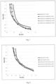
- Fig. 1 illustrates Rv/Ruv compromise, for four-layered antireflective stack comprising alternated zirconium oxide and silicon oxide (100%ZrO2 / SiO2), on a substrate of given refractive index.
- This graph is plotted according to the following method. A specific Rv value is selected. Then antireflective coating structure (i.e. thicknesses of each metal oxide layers) is optimized to reach the lowest Ruv value, for a reflected light having a given hue (green or gold) and a low chroma.
- Fig. 2 shows the Rv/Ruv compromise for four-layered antireflective stack, for three high refractive index materials, for green light reflected hue on substrate of refractive index 1.5.
- ZrO2 appears to be the best choice to reach simultaneously very low Rv and Ruv values.
- Ta2O5 is not as good as ZrO2, and Nb2O5 doesn't allow reaching Rv and Ruv values below 5%, which is a very poor performance.
- Ophthalmic lenses according to the invention are described on Fig. 3 to Fig. 10 .
- Fig. 3 shows Rv/Ruv compromises for four layered stacks using a composite layer of ZrO2 and Ta2O5 as high refractive index material on substrate of refractive index 1.5 and for green reflected light.
- the behavior of Rv/Ruv compromise curves for antireflective stacks with a composite layer is not an average curve located between Rv/Ruv compromises of four layered stacks using pure ZrO2 (solid line) or pure Ta2O5 (semi dotted line).
- using a composite as high refractive index material allows reaching simultaneously Rv and Ruv values lower than using a pure high refractive index material.
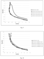
- Fig. 4 presents Rv/Ruv compromises for four layered antireflective stacks on a substrate of refractive index 1.6, according to the invention, using a composite layer of Nb2O5 and ZrO2 as high refractive index material and for gold reflected light.
- Rv/Ruv compromise curves for antireflective stacks with a composite layer allow reaching lower Rv and Ruv values simultaneously, as compared to antireflective stacks with pure high refractive index material.
- composite layer comprises less than 70% of Ta2O5 in weight, as compared to the total weight of the composite layer.
- composite layer comprises less than 23% of Nb2O5 in weight, as compared to the total weight of the composite layer.
- performance is worse than for pure ZrO2 (data not shown).
- composite layer comprises more than 30% of ZrO2 in weight, as compared to the total weight of the composite layer.
- mean light reflection factor Rv of main face of ophthalmic lens is lower than 1.25% for an angle of incidence comprised in the range 0°-20°.
- the mean reflection factor between 280 nm and 380 nm Ruv of main face of ophthalmic lens invention is lower than 7%, preferably lower than 5%, more preferably lower than 4%, even more preferably lower than 3%, ideally lower than 2% for an angle of incidence comprised in the range 30°-45°.
- Fig. 5 shows very interesting results for gold reflection with very low Rv values, below 0.65% for an angle of incidence of 15°, with ZrO2/Ta2O5 composites.
- Fig. 7 shows similar results for gold reflection with very low Rv values, below 0.65% for an angle of incidence of 15°, with ZrO2/Nb2O5 composites.
- Figure 9 shows very interesting results for gold reflections on high index substrates (1.6), with Rv below 0.65% for an angle of incidence of 15° and Ruv below 1.6% for an angle of incidence of 35°, with ZrO2/Ta2O5 composites.
- the light reflected by main face of ophthalmic lens has a chroma of less than 12 and a hue comprised in the range 30°-60°, for an angle of incidence comprised in the range 0°-20°. More particularly, with gold reflected light, Rv may be lower than 0.65% for an angle of incidence of 15° and Ruv may be lower than 2% for an angle of incidence of 35°, over a wide range of composition.
- light reflected by main face of ophthalmic lens has a chroma of less than 12 and a hue comprised in the range 120°-150°, for an angle of incidence comprised in the range 0°-20°.
Description
- The present invention relates to an ophthalmic lens comprising an antireflective stack which strongly reduces reflection in the UV range and in the visible range. The antireflective stack comprises composite high index layers.
- In the past few years, anti-UV function has been greatly emphasized due to the increasing concern on eye protection against ultra violet (UV) light. In particular, UV light coming from back or side of wearer should not be reflected towards wearer's eyes by the rear face of ophthalmic lenses. A very efficient antireflective property in the ultraviolet light range is required. This property is easily measured by Ruv, the mean reflection factor between 280 nm and 380nm, weighted by the function W(λ) defined in the ISO 13666:1998 standard. In the same time, a very efficient antireflective property in the visible range is required for the front face of the lens to avoid ghosts and cosmetically unpleasant reflected light. This property is easily measured by Rv, the mean reflection factor as defined in the ISO 13666:1998 standard.
- Unfortunately, when a stack is designed to minimize Ruv, Rv is usually too high. And when a stack is designed with a very low Rv, Ruv is usually not satisfying. The balance between Ruv and Rv should be improved.
- Inventors surprisingly discovered that using composite high index layers enables design of very efficient antireflective stack simultaneously for Ruv and Rv.
- Composite layers have been already used in antireflective stacks for various industries. US patent
US4260222 discloses three layered antireflective stacks in which a single composite layer of zirconium oxide and tantalum oxide is used. This composite layer is deposited in high temperature conditions, which are not suitable for organic ophthalmic lenses, and its composition provides a better uniformity of refractive index. However, antireflective performance in UV range is not considered, and is actually bad. - European patent
EP1211524 discloses four layered antireflective stacks for ophthalmic lenses in which high index layers are composite layers of Titanium oxide, Niobium oxide and zirconium oxide, providing improved mechanical and chemical characteristics to the antireflective stack. niobium oxide and titanium oxide are required as main components, in amount larger than 25% for niobium oxide. Actually, performance in UV range is not demonstrated. - Lenses coated with antireflective stacks are described in documents
EP2685293 ,WO201500534 US2015241602 . - A first object of the invention is an ophthalmic lens as defined in
independent claim 1. - A second object of the invention is a method as defined in
independent claim 10. -
-
Fig. 1 : Rv/Ruv compromise for SiO2/ZrO2 four layered stacks, on substrates of refractive index 1.5 (solid lines) or 1.6 (dotted lines), for a green reflected light (lines without marks) or gold reflected light (lines with diamonds). -
Fig. 2 : Rv/Ruv compromise for four layered stacks with SiO2 as low refractive index material and ZrO2 (solid line), Nb2O5 (semi dotted line) and Ta2O5 (dotted line) as high refractive index material, on substrate of refractive index 1.5 and for a green reflected light. -
Fig. 3 : Rv/Ruv compromise for composite layers of ZrO2/Ta2O5 of various compositions, on substrate of refractive index 1.5 and for a green reflected light. -
Fig. 4 : Rv/Ruv compromise for composite layers of ZrO2/Nb2O5 of various compositions, on substrate of refractive index 1.6 and for a gold reflected light. -
Fig. 5 : Rv/Ruv compromise for composite layers of ZrO2/Ta2O5 of various compositions, on substrate of refractive index 1.5 and for a green reflected light. -
Fig. 6 : Rv/Ruv compromise for composite layers of ZrO2/Nb2O5 of various compositions, on substrate of refractive index 1.5 and for a green reflected light. -
Fig. 7 : Rv/Ruv compromise for composite layers of ZrO2/Nb2O5 of various compositions, on substrate of refractive index 1.5 and for a gold reflected light. -
Fig. 8 : Rv/Ruv compromise for composite layers of ZrO2/Ta2O5 of various compositions, on substrate of refractive index 1.6 and for a green reflected light. -
Fig. 9 : Rv/Ruv compromise for composite layers of ZrO2/Ta2O5 of various compositions, on substrate of refractive index 1.6 and for a gold reflected light. -
Fig. 10 : Rv/Ruv compromise for composite layers of ZrO2/Nb2O5 of various compositions, on substrate of refractive index 1.6 and for a green reflected light. - Ophthalmic lens according to the invention comprises a substrate and an antireflective stack.
- Any substrate known in the ophthalmic industry is suitable for the invention, especially organic lens substrates, for example a thermoplastic or thermosetting plastic material.
- Thermoplastic may be selected from, for instance: polyamides; polyimide; polysulfones; polycarbonates and copolymers thereof; polyethylene terephtalate) and polymethylmethacrylate (PMMA).
- Thermoset materials may be selected from, for instance: cycloolefin copolymers such as ethylene/norbornene or ethylene/cyclopentadiene copolymers ; homo- and copolymers of allyl carbonates of linear or branched aliphatic or aromatic polyols, such as homopolymers of diethylene glycol bis(allyl carbonate) (CR 39®) ; homo- and copolymers of (meth)acrylic acid and esters thereof, which may be derived from bisphenol A ; polymer and copolymer of thio(meth)acrylic acid and esters thereof, polymer and copolymer of allyl esters which may be derived from Bisphenol A or phtalic acids and allyl aromatics such as styrene, polymer and copolymer of urethane and thiourethane, polymer and copolymer of epoxy, and polymer and copolymer of sulphide, disulfide and episulfide, and combinations thereof.
- As used herein, a (co)polymer is intended to mean a copolymer or a polymer. As used herein, a (meth)acrylate is intended to mean an acrylate or a methacrylate. As used herein, a polycarbonate (PC) is intended to mean either homopolycarbonates or copolycarbonates and block copolycarbonates.
- The antireflective coating may be deposited directly onto a bare substrate. In some applications, it is preferred for the front and/or rear main face of the substrate to be coated with one or more functional coatings prior to depositing the antireflective coating. These functional coatings traditionally used in optics may be, without limitation, an impact-resistant primer layer, an abrasion-resistant coating and/or a scratch-resistant coating, a polarizing coating, a photochromic coating or a tinted coating.
- Generally, the front and/or rear main face of the substrate onto which an antireflective coating will be deposited is coated with an impact-resistant primer layer, with an anti-abrasion and/or anti-scratch coating, or with an impact-resistant primer layer coated with an anti-abrasion and/or anti-scratch coating.
- Prior to depositing the abrasion-resistant coating and/or the scratch-resistant coating, it is possible to apply onto the substrate a primer coating to improve the impact resistance and/or the adhesion of the subsequent layers in the final product. This coating may be any impact-resistant primer layer traditionally used for articles in a transparent polymer material, such as ophthalmic lenses.
- In the following, "substrate" is intended to mean a coated or uncoated substrate.
- The substrate may also be pre-treated with a physical or chemical surface activating treatment, so as to reinforce the adhesion of the antireflective coating on the substrate. Such pre-treatment is generally conducted under vacuum. It may be a bombardment with energetic and/or reactive species, for example with an ion beam ("Ion Pre-Cleaning" or "IPC") or with an electron beam, a corona discharge treatment, an ion spallation treatment, an ultraviolet treatment or a plasma-mediated treatment under vacuum, generally using an oxygen or an argon plasma. It may also be an acid or basic treatment and/or a solvent-based treatment (water, hydrogen peroxide or any organic solvent).
- An antireflection coating, or stack, usually consists of a multilayer comprising interferential thin layers, generally an alternation of layers based on a dielectric material of high refractive index (HI) and a dielectric material of low refractive index (LI). When deposited on a transparent substrate, the function of such a coating is to reduce its light reflection and therefore to increase its light transmission.
- In the present invention, a layer of the antireflective coating is said to be a layer with a high refractive index (HI) when its refractive index is higher than or equal to 1,55, preferably higher than or equal to 1,6, even more preferably higher than or equal to 1,7, even more preferably higher than or equal to 1,8 and most preferably higher than or equal to 1,9.
- In the present invention, a layer of an antireflective coating is said to be a low refractive index layer (LI) when its refractive index is lower than 1,55, preferably lower than or equal to 1,50, more preferably lower than or equal to 1,48. Said LI layer preferably has a refractive index higher than 1,1.
- Unless otherwise specified, the refractive indexes referred to in the present application are expressed at 25 °C at a wavelength of 550 nm.
- The antireflection stack of the invention comprises at least one composite layer comprising zirconium oxide and another metal oxide.
- In some embodiments, the antireflection stack of the invention comprises at least two composite layers comprising zirconium oxide and another metal oxide,.
- In some embodiments, said composite layer has a refractive index higher than 1.6, preferably higher than 1.7, more preferably higher than 1.8, ideally higher than 1.9. With composite layers of refractive index higher than 1.9, Rv/Ruv compromise is improved.
- Suitable metal oxide in composite layer are, besides zirconium oxide (ZrO2) and without limitations, titanium dioxide (TiO2), alumina (Al2O3), tantalum pentoxide (Ta2O5), neodymium oxide (Nd2O5), praseodymium oxide (Pr2O3), praseodymium titanate (PrTiO3), lanthanum oxide (La2O3), niobium oxide (Nb2O5), yttrium oxide (Y2O3). Optionally, the composite layer may further contain silica or other materials with a low refractive index, provided the composite layer has a refractive index higher than or equal to 1,55.
- For all metal oxides, the composition is intended to encompass a range of compositions around the exact stoichiometric value, plus or minus 5%. For instance, ZrO2 encompasses all metal oxides with composition ZrOx, 1.9<x<2.1.
- As titanium oxide (TiO2) and yttrium oxide (Y2O3) are slightly dispersive in UV-violet light domain, these metal oxides are less preferred. Specific embodiments of the invention do not contain any of these metal oxides.
- The preferred metal oxides include tantalum pentoxide (Ta2O5) and niobium oxide (Nb2O5).
- The LI layer may comprise, without limitation, SiO2, or a mixture of silica and alumina, especially silica doped with alumina, the latter contributing to increase the antireflective coating thermal resistance. The LI layer is preferably a layer comprising at least 80% by weight of silica, more preferably at least 90% by weight of silica, relative to the layer total weight, and even more preferably consists in a silica layer.
- Optionally, the LI layers may further contain materials with a high refractive index, provided the refractive index of the resulting layer is lower than 1,55.
- In the invention, the antireflective coating total thickness is lower than 1 micrometer, preferably lower than or equal to 800 nm, more preferably lower than or equal to 500 nm and even more preferably lower than or equal to 250 nm. The antireflective coating total thickness is generally higher than 100 nm, preferably higher than 150 nm.
- In some embodiments of the present invention, the antireflective coating is deposited onto a sub-layer. It should be noted that such antireflective coating sub-layer does not belong to the antireflective coating.
- As used herein, an antireflective coating sub-layer or adhesion layer is intended to mean a relatively thick coating, used in order to improve the mechanical properties such as the abrasion resistance and/or the scratch resistance of said coating and/or so as to reinforce its adhesion to the substrate or to the underlying substrate.
- Because of its relatively high thickness, the sub-layer does not generally take part to the antireflective optical activity, especially when it has a refractive index close to that of the underlying substrate.
- The sub-layer should have a thickness that is sufficient for promoting the abrasion resistance of the antireflective coating, but preferably not to such an extent that a light absorption could be caused, which, depending on the sub-layer nature, could significantly reduce the relative transmission factor Tv. Its thickness is generally lower than 500 nm, preferably lower than 300 nm, more preferably lower than 200 nm, and is generally higher than 90 nm, more preferably higher than 100 nm.
- The sub-layer preferably comprises a SiO2-based layer, this layer comprising preferably at least 80% by weight of silica, more preferably at least 90% by weight of silica, relative to the layer total weight.
- In another embodiment, this SiO2-based layer is a silica layer doped with alumina, in amounts such as defined hereabove, preferably consists in a silica layer doped with alumina.
- In a particular embodiment, the sub-layer consists in a SiO2 layer.
- The various layers of the antireflective coating and the optional sub-layer are preferably deposited by physical vapor deposition, under vacuum, according to any of the following methods:
- i) by optionally ion-beam assisted, evaporation;
- ii) by ion-beam sputtering;
- iii) by cathode sputtering;
- iv) by plasma-assisted chemical vapor deposition.
- These various methods are described in the following references "Thin Film Processes" and "Thin Film Processes II," Vossen & Kern, Ed., Academic Press, 1978 and 1991, respectively. A particularly recommended method is the evaporation under vacuum. Preferably, the deposition of each of the layers of the antireflective coating and of the optional sub-layer is conducted by evaporation under vacuum.
- Especially, the composite layer of the invention may be deposited by simultaneous evaporation from two distinct sources of pure ZrO2 in one crucible and pure other metal oxide in a second crucible; and control of evaporation rates from each crucible to obtain the weight composition of the composite layer. Alternatively, the composite layer may be deposited from evaporation of a single composite source. This composite source is typically obtained by mixing powder of ZrO2 and powder of metal oxide in weight proportions expected for composite layer composition.
- The ophthalmic lens of the invention may be made antistatic, that is to say not to retain and/or develop a substantial static charge, by incorporating at least one charge dissipating conductive layer into the antireflective coating present on the surface of the article.
- The ophthalmic lens according to the invention may also comprise coatings formed on the antireflective coating and capable of modifying the surface properties thereof, such as hydrophobic and/or oleophobic coatings (antifouling top coat). These coatings are preferably deposited onto the outer layer of the antireflective coating.
- Typically, an ophthalmic lens according to the invention comprises a substrate that is coated on at least on face with an impact-resistant primer layer, an anti-abrasion and scratch-resistant layer, an antireflective coating according to the invention, and with a hydrophobic and/or oleophobic coating, or with a hydrophilic coating which provides antifog properties, or an antifog precursor coating.
- The ophthalmic lens according to the invention is preferably an ophthalmic lens for spectacles (spectacle lens), or a blank for ophthalmic lenses.
- As stated above, the function of an antireflection coating is to reduce light reflection and therefore to increase light transmission through the substrate on which it has been laid. These optical characteristics are measured with colorimetric coefficients and reflection factors, for several angles of incidence.
- The "angle of incidence" is the angle formed by a ray light incident on an ophthalmic lens surface and a normal to the surface at the point of incidence. The ray light is for instance an illuminant light source, such as the standard illuminant D65 as defined in the international colorimetric CIE L*a*b*. Generally the angle of incidence changes from 0° (normal incidence) to 90° (grazing incidence). The usual range for angle of incidence is from 0° to 75°.
- The colorimetric coefficients of the ophthalmic lens of the invention in the international colorimetric system CIE L*a*b* are calculated between 380 and 780 nm, taking the standard illuminant D 65 and the observer into account (angle of 10°). It is possible to prepare antireflective coatings, without limitation as regards their hue angle. The observer is a "standard observer" as defined in the international colorimetric system CIE L*a*b*.
- For aesthetic reasons, hue of the reflected light, for an angle of incidence comprised in the
range 0°-20°, is preferably green (120°<hue<150°), gold (30°<hue<60°), blue (240°<hue<280°) or violet/purple (300°<hue<340°). The desired chroma of the reflected light, for an angle of incidence comprised in therange 0°-20°, is lower than 15, preferably lower than 12. A chroma of 9 is generally considered as good for aesthetic reasons. - The "mean light reflection factor", noted Rv, is such as defined in the ISO 13666:1998 Standard, and measured in accordance with the ISO 8980-4, i.e. this is the weighted spectral reflection average over the whole visible spectrum between 380 and 780 nm. Rv is usually measured for an angle of incidence lower than 17°, typically of 15°, but can be evaluated for any angle of incidence.
- The mean reflection factor between 280 nm and 380 nm, weighted by the W(λ) function defined according to the ISO 13666:1998 Standard and noted Ruv, may be defined through the following relation:

- The mean reflection factor between 280 nm and 380 nm Ruv on main face of ophthalmic lens of the invention is lower than 7%, preferably lower than 5%, more preferably lower than 4%, even more preferably lower than 3%, ideally lower than 2% for an angle of incidence comprised in the
range 30°-45°, preferably for an angle of incidence of 35°. - The mean light reflection factor Rv on main face of ophthalmic lens of the invention is preferably lower than 1.25%, for an angle of incidence comprised in the
range 0°-20°. - An antireflective coating, depending on its structure (nature of metal oxides, number and thickness of layers) and on the refractive index of the substrate, will present specific colorimetric and reflection characteristics. Obtaining a balance of all properties is the art of antireflective coating design.
- In particular, Rv and Ruv reflection factors are correlated, and it's not possible to minimize simultaneously Rv and Ruv as one would desire.
- In all following examples, antireflective stacks are four layered stacks comprising alternating low refractive index material and high refractive index material. Low refractive index material is always pure SiO2. In comparative examples, high refractive index material is a pure mineral oxide, actually ZrO2, Ta2O5 or Nb2O5. In inventive examples, high refractive index material is a composite comprising ZrO2, actually composite of ZrO2 and Ta2O5 or composite of ZrO2 and Nb2O5.
- The exact composition of the antireflective stack is represented by the following formula:
High refractive index material / SiO2
- In which high refractive index material composition is represented by
N% Oxide1 - (100-N)% Oxide2
- For instance, the following antireflective stack: 90%ZrO2 - 10%Ta2O5 / SiO2 represents a four layered stack comprising, in the direction moving away from substrate, one layer of composite comprising 90% ZrO2 and 10% Ta2O5, one layer of SiO2, one layer of composite comprising 90% ZrO2 and 10% Ta2O5 and last, one layer of SiO2.
- For comparative examples, N=100 and Oxide1 is either ZrO2 or Ta2O5 or Nb2O5.
- In all following examples, Rv is evaluated for an angle of incidence of 15° and Ruv is evaluated for an angle of incidence of 35°. Chroma is always set to 9. Reflected light is either green (hue=135°) or gold (hue=45°). Refractive index of substrate is either 1.5 or 1.6. Calculations are performed with standard software, such as
MacLeod version 10, available from Thin Film Center. -
Fig. 1 illustrates Rv/Ruv compromise, for four-layered antireflective stack comprising alternated zirconium oxide and silicon oxide (100%ZrO2 / SiO2), on a substrate of given refractive index. This graph is plotted according to the following method. A specific Rv value is selected. Then antireflective coating structure (i.e. thicknesses of each metal oxide layers) is optimized to reach the lowest Ruv value, for a reflected light having a given hue (green or gold) and a low chroma. - From
Fig. 1 , one learns that antireflective coatings can not reach the domain below the curve, for the targeted colorimetric performances and substrate, using only pure zirconium oxide as high refractive index material and pure silicon oxide as low refractive index material. -
Fig. 2 shows the Rv/Ruv compromise for four-layered antireflective stack, for three high refractive index materials, for green light reflected hue on substrate of refractive index 1.5. ZrO2 appears to be the best choice to reach simultaneously very low Rv and Ruv values. Ta2O5 is not as good as ZrO2, and Nb2O5 doesn't allow reaching Rv and Ruv values below 5%, which is a very poor performance. - Ophthalmic lenses according to the invention are described on
Fig. 3 to Fig. 10 . -
Fig. 3 shows Rv/Ruv compromises for four layered stacks using a composite layer of ZrO2 and Ta2O5 as high refractive index material on substrate of refractive index 1.5 and for green reflected light. Surprisingly, the behavior of Rv/Ruv compromise curves for antireflective stacks with a composite layer is not an average curve located between Rv/Ruv compromises of four layered stacks using pure ZrO2 (solid line) or pure Ta2O5 (semi dotted line). Actually, using a composite as high refractive index material allows reaching simultaneously Rv and Ruv values lower than using a pure high refractive index material. For instance, with Ruv=1.5%, a stack using pure ZrO2 will have Rv=0.87% in the best conditions. With a composite comprising 10% Ta2O5 in weight, Rv=0.83% in the best conditions. With 30% or 50% Ta2O5 in weight, Rv may reach 0.80%. Such a variation is significant for antireflective properties. - More precisely, one can observe that the composites with high content of Ta2O5 (50%, curve with circles) are interesting for Rv values below 1%. Composites with lower content of Ta2O5 (10%, curve with squares) perform always better than pure ZrO2, but with smaller improvement.
- Similarly,
Fig. 4 presents Rv/Ruv compromises for four layered antireflective stacks on a substrate of refractive index 1.6, according to the invention, using a composite layer of Nb2O5 and ZrO2 as high refractive index material and for gold reflected light. Again, Rv/Ruv compromise curves for antireflective stacks with a composite layer allow reaching lower Rv and Ruv values simultaneously, as compared to antireflective stacks with pure high refractive index material. Adding Nb2O5 high refractive index material brings a clear benefit to design antireflective stacks with simultaneously low Rv and Ruv values. With Ruv=1.2%, the use of composite layers allows lowering of Rv value of almost 0.1%, which is very significant for antireflective properties. - Similar results are presented in
Figures 5 to 10 , in which parameters of reflected light color (green, gold) and refractive index of substrate (1.5 and 1.6) are systematically varied. - In a specific embodiment of the invention, composite layer comprises less than 70% of Ta2O5 in weight, as compared to the total weight of the composite layer.
- In another specific embodiment of the invention, composite layer comprises less than 23% of Nb2O5 in weight, as compared to the total weight of the composite layer. For composite comprising more than 25% of Nb2O5 in weight, performance is worse than for pure ZrO2 (data not shown).
- In particular embodiments of the invention, composite layer comprises more than 30% of ZrO2 in weight, as compared to the total weight of the composite layer.
- From
figures 3 to 10 , one recognizes that Rv value lower than 1.25% is easily obtained, and that Ruv value lower than 2.5% is also easily obtained. - In some embodiments of the invention, mean light reflection factor Rv of main face of ophthalmic lens is lower than 1.25% for an angle of incidence comprised in the
range 0°-20°. - In other embodiments of the invention, the mean reflection factor between 280 nm and 380 nm Ruv of main face of ophthalmic lens invention is lower than 7%, preferably lower than 5%, more preferably lower than 4%, even more preferably lower than 3%, ideally lower than 2% for an angle of incidence comprised in the
range 30°-45°. - From a careful analysis, one observes that depending on reflected light color and refractive index of substrate parameters, associations of materials are more valuable.
-
Fig. 5 shows very interesting results for gold reflection with very low Rv values, below 0.65% for an angle of incidence of 15°, with ZrO2/Ta2O5 composites. -
Fig. 7 shows similar results for gold reflection with very low Rv values, below 0.65% for an angle of incidence of 15°, with ZrO2/Nb2O5 composites. -
Figure 9 shows very interesting results for gold reflections on high index substrates (1.6), with Rv below 0.65% for an angle of incidence of 15° and Ruv below 1.6% for an angle of incidence of 35°, with ZrO2/Ta2O5 composites. - In some embodiments of the invention, the light reflected by main face of ophthalmic lens has a chroma of less than 12 and a hue comprised in the
range 30°-60°, for an angle of incidence comprised in therange 0°-20°. More particularly, with gold reflected light, Rv may be lower than 0.65% for an angle of incidence of 15° and Ruv may be lower than 2% for an angle of incidence of 35°, over a wide range of composition. - In other embodiments of the invention, light reflected by main face of ophthalmic lens has a chroma of less than 12 and a hue comprised in the range 120°-150°, for an angle of incidence comprised in the
range 0°-20°.
Claims (10)
- Ophthalmic lens comprising a substrate with a rear main face; said rear main face being coated with an antireflective stack, characterized in that the antireflective stack comprises at least one composite layer comprising• zirconium oxide and 50% or more and less than 70% of tantalum oxide in weight as compared to the total weight of the composite layer; or• zirconium oxide and less than 23% of niobium oxide in weight as compared to the total weight of the composite layerthe mean reflection factor Ruv on said rear main face, between 280 nm and 380nm weighted by the function W(λ) defined in the ISO 13666:1998 standard being lower than 7%, for an angle of incidence comprised in the range 30°-45°, andthe mean light reflection factor Rv on said rear main face being lower than 1.25%, for an angle of incidence comprised in the range 0°-20°.
- Ophthalmic lens according to claim 1, characterized in that the antireflective stack comprises at least two composite layers each composite layer being as defined in claim 1.
- Ophthalmic lens according to claim 1 or 2, characterized in that the composite layer comprises more than 30% of zirconium oxide in weight as compared to the total weight of the composite layer.
- Ophthalmic lens according to anyone of claims 1 to 3, characterized in that the composite layer has a refractive index higher than 1.6.
- Ophthalmic lens according to anyone of claims 1 to 4, characterized in that the mean reflection factor between 280 nm and 380 nm Ruv on said main face is lower than 5%, for an angle of incidence comprised in the range 30°-45°.
- Ophthalmic lens according to anyone of claims 1 to 5, characterized in that the mean reflection factor between 280 nm and 380 nm Ruv on said main face is lower than 3%, for an angle of incidence comprised in the range 30°-45°.
- Ophthalmic lens according to anyone of claims 1 to 6, characterized in that the mean reflection factor between 280 nm and 380 nm Ruv on said main face is lower than 2%, for an angle of incidence comprised in the range 30°-45°.
- Ophthalmic lens according to anyone of claims 1 to 7, characterized in that the reflected light reflected by said main face has a chroma of less than 12 and a hue comprised in the range 120°-150°, for an angle of incidence comprised in the range 0°-20°.
- Ophthalmic lens according to anyone of claims 1 to 7, characterized in that the reflected light reflected by said main face has a chroma of less than 12 and a hue comprised in the range 30°-60°, for an angle of incidence comprised in the range 0°-20°.
- Method to prepare an ophthalmic lens according to anyone of claims 1 to 9 characterized in that zirconium oxide and either tantalum oxide or niobium oxide are simultaneously evaporated in a vacuum deposition step.
Priority Applications (3)
| Application Number | Priority Date | Filing Date | Title |
|---|---|---|---|
| EP15307049.5A EP3182177B1 (en) | 2015-12-18 | 2015-12-18 | Composite high index layers for anti reflective stacks |
| US15/381,865 US10234697B2 (en) | 2015-12-18 | 2016-12-16 | Composite high index layers for anti reflective stacks |
| CN201611175896.2A CN106896423B (en) | 2015-12-18 | 2016-12-19 | Composite high refractive index layer for antireflective stacks |
Applications Claiming Priority (1)
| Application Number | Priority Date | Filing Date | Title |
|---|---|---|---|
| EP15307049.5A EP3182177B1 (en) | 2015-12-18 | 2015-12-18 | Composite high index layers for anti reflective stacks |
Publications (2)
| Publication Number | Publication Date |
|---|---|
| EP3182177A1 EP3182177A1 (en) | 2017-06-21 |
| EP3182177B1 true EP3182177B1 (en) | 2024-02-28 |
Family
ID=55066496
Family Applications (1)
| Application Number | Title | Priority Date | Filing Date |
|---|---|---|---|
| EP15307049.5A Active EP3182177B1 (en) | 2015-12-18 | 2015-12-18 | Composite high index layers for anti reflective stacks |
Country Status (3)
| Country | Link |
|---|---|
| US (1) | US10234697B2 (en) |
| EP (1) | EP3182177B1 (en) |
| CN (1) | CN106896423B (en) |
Families Citing this family (6)
| Publication number | Priority date | Publication date | Assignee | Title |
|---|---|---|---|---|
| WO2019046441A1 (en) * | 2017-08-29 | 2019-03-07 | General Plasma Inc. | Multilayer antireflective articles and methods of forming the same |
| WO2020016620A1 (en) * | 2018-07-18 | 2020-01-23 | Essilor International | Optical article with improved antireflective coating, methods for making the same |
| BR112021011933A2 (en) * | 2018-12-18 | 2021-09-08 | Essilor International | OPTICAL ARTICLE HAVING A REFLECTIVE COATING WITH HIGH ABRASION RESISTANCE |
| EP3693765B1 (en) * | 2019-02-05 | 2023-04-19 | Essilor International | Article coated with an antireflective coating having improved optical properties |
| CN109652775A (en) * | 2019-02-14 | 2019-04-19 | 江苏万新光学有限公司 | A kind of film plating process of the double-deck yellowish green film glass of low reflection |
| US20230176253A1 (en) | 2020-04-09 | 2023-06-08 | Essilor International | Optical article with antibacterial function |
Citations (4)
| Publication number | Priority date | Publication date | Assignee | Title |
|---|---|---|---|---|
| US4260222A (en) * | 1978-07-11 | 1981-04-07 | Olympus Optical Co., Ltd. | Multi-layer non-reflecting film |
| EP1211524A2 (en) * | 2000-11-30 | 2002-06-05 | Hoya Corporation | Method for producing composition for vapor deposition, composition for vapor deposition, and method for producing optical element with antireflection film |
| US20110229659A1 (en) * | 2010-03-22 | 2011-09-22 | Timothy Ray Reynolds | Ion beam assisted deposition of ophthalmic lens coatings |
| US20150234208A1 (en) * | 2012-05-16 | 2015-08-20 | Essilor International (Compagnie Generale D'optique) | Ophthalmic lens |
Family Cites Families (4)
| Publication number | Priority date | Publication date | Assignee | Title |
|---|---|---|---|---|
| US7692855B2 (en) * | 2006-06-28 | 2010-04-06 | Essilor International Compagnie Generale D'optique | Optical article having a temperature-resistant anti-reflection coating with optimized thickness ratio of low index and high index layers |
| FR2968774B1 (en) * | 2010-12-10 | 2013-02-08 | Essilor Int | OPTICAL ARTICLE COMPRISING A LOW REFLECTIVE ANTIREFLECTION COATING IN THE ULTRAVIOLET DOMAIN AND THE VISIBLE DOMAIN |
| WO2015000534A1 (en) * | 2013-07-05 | 2015-01-08 | Essilor International (Compagnie Generale D'optique) | Optical article comprising an antireflective coating with a very low reflection in the visible region |
| US9291746B2 (en) * | 2014-02-25 | 2016-03-22 | iCoat Company, LLC | Visible spectrum anti-reflective coatings with reduced reflections in ultraviolet and infrared spectral bands |
-
2015
- 2015-12-18 EP EP15307049.5A patent/EP3182177B1/en active Active
-
2016
- 2016-12-16 US US15/381,865 patent/US10234697B2/en active Active
- 2016-12-19 CN CN201611175896.2A patent/CN106896423B/en active Active
Patent Citations (4)
| Publication number | Priority date | Publication date | Assignee | Title |
|---|---|---|---|---|
| US4260222A (en) * | 1978-07-11 | 1981-04-07 | Olympus Optical Co., Ltd. | Multi-layer non-reflecting film |
| EP1211524A2 (en) * | 2000-11-30 | 2002-06-05 | Hoya Corporation | Method for producing composition for vapor deposition, composition for vapor deposition, and method for producing optical element with antireflection film |
| US20110229659A1 (en) * | 2010-03-22 | 2011-09-22 | Timothy Ray Reynolds | Ion beam assisted deposition of ophthalmic lens coatings |
| US20150234208A1 (en) * | 2012-05-16 | 2015-08-20 | Essilor International (Compagnie Generale D'optique) | Ophthalmic lens |
Also Published As
| Publication number | Publication date |
|---|---|
| CN106896423B (en) | 2020-06-16 |
| US20170299887A1 (en) | 2017-10-19 |
| US10234697B2 (en) | 2019-03-19 |
| CN106896423A (en) | 2017-06-27 |
| EP3182177A1 (en) | 2017-06-21 |
Similar Documents
| Publication | Publication Date | Title |
|---|---|---|
| US10234697B2 (en) | Composite high index layers for anti reflective stacks | |
| EP3140692B1 (en) | Optical article comprising an antireflective coating with a very low reflection in the visible and ultraviolet regions | |
| US10481413B2 (en) | Optical article comprising an antireflective coating in the visible region for low luminance conditions | |
| CN109791219B (en) | Optical lens comprising an antireflection coating with multi-angle efficiency | |
| US11397285B2 (en) | Optical article having an abrasion and temperature resistant interferential coating with an optimized thickness ratio of low and high refractive index layers | |
| CN107111000B (en) | Including the optical article in ultraviolet region interference coatings with high reflectivity | |
| CN106662671B (en) | Optical article comprising an antireflection coating having a low reflection in both the ultraviolet and visible regions | |
| US20220011600A1 (en) | Optical Lens Having an Interferential Coating and a Multilayer System for Improving Abrasion-Resistance | |
| US9835767B2 (en) | Adaptation layer for antireflective designs on lenses of various refractive indexes | |
| US11592597B2 (en) | Anti-reflective sputtering stack with low Rv and low Ruv | |
| EP3884314B1 (en) | Optical lens having a mirror coating and a multilayer system for improving abrasion-resistance | |
| CN112867945B (en) | Optical article with interference coating having improved abrasion resistance | |
| EP3640687A1 (en) | Optical article having an interferential coating with a high abrasion-resistance |
Legal Events
| Date | Code | Title | Description |
|---|---|---|---|
| PUAI | Public reference made under article 153(3) epc to a published international application that has entered the european phase |
Free format text: ORIGINAL CODE: 0009012 |
|
| STAA | Information on the status of an ep patent application or granted ep patent |
Free format text: STATUS: THE APPLICATION HAS BEEN PUBLISHED |
|
| AK | Designated contracting states |
Kind code of ref document: A1 Designated state(s): AL AT BE BG CH CY CZ DE DK EE ES FI FR GB GR HR HU IE IS IT LI LT LU LV MC MK MT NL NO PL PT RO RS SE SI SK SM TR |
|
| AX | Request for extension of the european patent |
Extension state: BA ME |
|
| STAA | Information on the status of an ep patent application or granted ep patent |
Free format text: STATUS: REQUEST FOR EXAMINATION WAS MADE |
|
| RAP1 | Party data changed (applicant data changed or rights of an application transferred) |
Owner name: ESSILOR INTERNATIONAL |
|
| 17P | Request for examination filed |
Effective date: 20171219 |
|
| RBV | Designated contracting states (corrected) |
Designated state(s): AL AT BE BG CH CY CZ DE DK EE ES FI FR GB GR HR HU IE IS IT LI LT LU LV MC MK MT NL NO PL PT RO RS SE SI SK SM TR |
|
| STAA | Information on the status of an ep patent application or granted ep patent |
Free format text: STATUS: EXAMINATION IS IN PROGRESS |
|
| 17Q | First examination report despatched |
Effective date: 20210324 |
|
| STAA | Information on the status of an ep patent application or granted ep patent |
Free format text: STATUS: EXAMINATION IS IN PROGRESS |
|
| P01 | Opt-out of the competence of the unified patent court (upc) registered |
Effective date: 20230525 |
|
| GRAP | Despatch of communication of intention to grant a patent |
Free format text: ORIGINAL CODE: EPIDOSNIGR1 |
|
| STAA | Information on the status of an ep patent application or granted ep patent |
Free format text: STATUS: GRANT OF PATENT IS INTENDED |
|
| INTG | Intention to grant announced |
Effective date: 20230928 |
|
| GRAS | Grant fee paid |
Free format text: ORIGINAL CODE: EPIDOSNIGR3 |
|
| GRAA | (expected) grant |
Free format text: ORIGINAL CODE: 0009210 |
|
| STAA | Information on the status of an ep patent application or granted ep patent |
Free format text: STATUS: THE PATENT HAS BEEN GRANTED |
|
| AK | Designated contracting states |
Kind code of ref document: B1 Designated state(s): AL AT BE BG CH CY CZ DE DK EE ES FI FR GB GR HR HU IE IS IT LI LT LU LV MC MK MT NL NO PL PT RO RS SE SI SK SM TR |
|
| REG | Reference to a national code |
Ref country code: GB Ref legal event code: FG4D |
|
| REG | Reference to a national code |
Ref country code: CH Ref legal event code: EP |
|
| REG | Reference to a national code |
Ref country code: DE Ref legal event code: R096 Ref document number: 602015087694 Country of ref document: DE |
|
| REG | Reference to a national code |
Ref country code: IE Ref legal event code: FG4D |