EP2648947B2 - Soupape de frein de service comportant au moins un commutateur électrique pouvant être directement actionné par un piston-relais - Google Patents
Soupape de frein de service comportant au moins un commutateur électrique pouvant être directement actionné par un piston-relais Download PDFInfo
- Publication number
- EP2648947B2 EP2648947B2 EP11794460.3A EP11794460A EP2648947B2 EP 2648947 B2 EP2648947 B2 EP 2648947B2 EP 11794460 A EP11794460 A EP 11794460A EP 2648947 B2 EP2648947 B2 EP 2648947B2
- Authority
- EP
- European Patent Office
- Prior art keywords
- relay piston
- service brake
- brake valve
- housing
- electric switch
- Prior art date
- Legal status (The legal status is an assumption and is not a legal conclusion. Google has not performed a legal analysis and makes no representation as to the accuracy of the status listed.)
- Active
Links
Images
Classifications
-
- B—PERFORMING OPERATIONS; TRANSPORTING
- B60—VEHICLES IN GENERAL
- B60T—VEHICLE BRAKE CONTROL SYSTEMS OR PARTS THEREOF; BRAKE CONTROL SYSTEMS OR PARTS THEREOF, IN GENERAL; ARRANGEMENT OF BRAKING ELEMENTS ON VEHICLES IN GENERAL; PORTABLE DEVICES FOR PREVENTING UNWANTED MOVEMENT OF VEHICLES; VEHICLE MODIFICATIONS TO FACILITATE COOLING OF BRAKES
- B60T7/00—Brake-action initiating means
- B60T7/02—Brake-action initiating means for personal initiation
- B60T7/04—Brake-action initiating means for personal initiation foot actuated
- B60T7/042—Brake-action initiating means for personal initiation foot actuated by electrical means, e.g. using travel or force sensors
-
- B—PERFORMING OPERATIONS; TRANSPORTING
- B60—VEHICLES IN GENERAL
- B60T—VEHICLE BRAKE CONTROL SYSTEMS OR PARTS THEREOF; BRAKE CONTROL SYSTEMS OR PARTS THEREOF, IN GENERAL; ARRANGEMENT OF BRAKING ELEMENTS ON VEHICLES IN GENERAL; PORTABLE DEVICES FOR PREVENTING UNWANTED MOVEMENT OF VEHICLES; VEHICLE MODIFICATIONS TO FACILITATE COOLING OF BRAKES
- B60T15/00—Construction arrangement, or operation of valves incorporated in power brake systems and not covered by groups B60T11/00 or B60T13/00
- B60T15/02—Application and release valves
- B60T15/04—Driver's valves
- B60T15/043—Driver's valves controlling service pressure brakes
-
- B—PERFORMING OPERATIONS; TRANSPORTING
- B60—VEHICLES IN GENERAL
- B60T—VEHICLE BRAKE CONTROL SYSTEMS OR PARTS THEREOF; BRAKE CONTROL SYSTEMS OR PARTS THEREOF, IN GENERAL; ARRANGEMENT OF BRAKING ELEMENTS ON VEHICLES IN GENERAL; PORTABLE DEVICES FOR PREVENTING UNWANTED MOVEMENT OF VEHICLES; VEHICLE MODIFICATIONS TO FACILITATE COOLING OF BRAKES
- B60T15/00—Construction arrangement, or operation of valves incorporated in power brake systems and not covered by groups B60T11/00 or B60T13/00
- B60T15/02—Application and release valves
- B60T15/04—Driver's valves
- B60T15/14—Driver's valves influencing electric control means
Definitions
- the invention is based on a service brake valve for at least one pneumatic brake circuit of a pneumatic or electro-pneumatic brake device of a vehicle, including a service brake valve housing, a tappet that can be actuated by a foot brake plate, a tappet holder with a spring plate, and spring means for transmitting the actuating forces acting on the tappet at least one relay piston and at least one electrical switch for changing an electrical signal immediately after actuation of the foot brake plate, according to the preamble of claim 1.
- actuation of the foot brake plate of the service brake valve causes the plunger to actuate the relay piston via the spring plate in order to generate a control pressure for downstream pneumatic brake valves that corresponds to the brake request, to create a redundant brake pressure that becomes effective in the brake cylinders when the priority electrical Brake circuit has failed due to a defect.
- a generic service brake valve is from DE 27 24 179 A known, where a plunger protrudes into a recess of a plunger receptacle which is connected by a shaft to a spring plate which actuates a relay piston by spring means.
- the spring plate also actuates a number of microswitches, which are arranged laterally in a housing of the service brake valve, via a complex lever mechanism which, among other things, contains an actuation lever.
- the microswitches generate an electrical signal to operate a retarder when the foot brake plate is stepped on.
- both brake circuits must therefore always be able to respond when the foot brake plate is actuated. This should always be the case, and therefore in particular also, when, for example, a utility vehicle equipped with such a braking device is rolling downhill with the ignition switched off.
- the electrical switch is used to generate an electrical signal or to change the electrical signal previously generated by it in order to activate the electrical brake circuit, which is actually deactivated by the switched-off ignition, whereby the electrical brake circuit is also activated in addition to the pneumatic brake circuit, which is operated anyway Brake circuit is available.
- the electrical switch with which the activation of the further brake circuit such as an electrical brake circuit or a retarder takes place is usually a microswitch.
- This is generally understood to mean an electrical switch whose contacts are less than 3 mm in the open state Have a distance from each other.
- a known design is, for example, the microswitch with a snap system.
- designs as NC and NO contacts and as changeover contacts with the three connections NC contact, NO contact and switch tongue are known. Due to the small contact distance, microswitches are only suitable for switching low loads.
- microswitches are used to generate the position of movable components, such as components of a service brake valve described at the outset, in particular in their function as limit switches.
- the present invention is therefore based on the object of further developing a service brake valve of the type mentioned in the introduction in such a way that it is more compact and the actuating movement is mechanically transmitted to the electrical switch with as little flexibility as possible.
- the invention is based on the idea that actuation of service brake valves includes three phases.
- the tappet and the spring plate on the one hand and the relay piston driven with the spring plate by the spring means on the other hand initially move synchronously and together.
- a counterpressure builds up on the relay piston, which operates a double-seat valve, so that the relay piston weighs out and is inhibited in its further movement, so that in this second phase the tappet, which is still operated by the foot brake plate, and the The spring retainer covers a greater distance than the relay piston.
- the plunger and the spring plate on the one hand and the relay piston on the other hand move synchronously and together.
- the electrical switch is therefore actuated directly by the relay piston.
- the electrical switch is arranged in or on the service brake valve housing in such a way that it can be actuated directly by the relay piston without the provision of transmission elements.
- the electrical switch is held in the service brake valve housing and arranged, for example, in such a way that an end face of the relay piston arranged perpendicular to the direction of movement of the relay piston directly actuates an actuator of the electrical switch, the actuation direction of the actuator of the electrical switch being parallel to the direction of movement of the relay piston.
- the electrical switch is held in a housing cover of the service brake valve housing that has an upper stop for an end face of the relay piston arranged perpendicular to the direction of movement of the relay piston, in particular in a recess of a cylindrical wall of the housing cover that is at least partially open towards the relay piston.
- the housing cover is then, for example, inserted into a further housing part of the service brake valve housing or centered there.
- the upper stop for the relay piston is formed, for example, by an end face section of the housing cover which is arranged perpendicular to the direction of movement of the relay piston.
- the electrical switch is a microswitch and its actuator is designed as a button-like pin protruding from a housing of the microswitch, which cooperates from the end face of the relay piston and can be actuated directly by the latter.
- the electrical switch is particularly preferably provided for activating an electrical brake circuit of the braking device in order to meet the legal requirements with regard to two brake circuits that are always available.
- the electrical switch generates a signal representing a released brake and in a position in which the relay piston has just been lifted from the stop on the housing cover of the service brake valve housing , a signal representing a brake request signal or an applied brake.
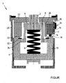
- the upper part of a service brake valve 1 shown in FIG. 1 is integrated, according to a preferred embodiment, into a foot brake module of an electropneumatic brake system of a commercial vehicle.
- the brake system has, for example, one electrical and at least one pneumatic brake circuit.
- Such a foot brake module is well known, for example from the Kraftfahrischen Taschenbuch, published by Robert Bosch GmbH, 26th edition 2007, pages 876 to 877 .
- the service brake valve 1 contains, inter alia, a tappet 2 actuated by a foot brake plate (not shown here) which interacts with a piston-like tappet receptacle 6 which is axially movable in a service brake valve housing 4.
- This tappet receptacle 6 has a spring plate 8 on which spring means, in particular a helical compression spring 9, are supported, which on the other hand are supported on a reaction piston 10.
- the relay piston 10 acts in a known manner on a double seat valve in order to generate a control pressure or brake pressure for the at least one pneumatic brake circuit in at least one pneumatic channel.
- a sensor device which is likewise not visible here, is provided in order to generate an electrical signal corresponding to an actuation of the foot brake plate for an electrical channel of the service brake valve 1, which in turn is assigned to the electrical brake circuit.
- the relay piston 10 actuates at least one electrical switch, here preferably a microswitch 12 such that the microswitch 12 generates or changes an electrical signal (connection or disconnection of an electrical circuit) and thereby a certain position of the reaction piston 10 relative to the service brake valve housing 4 or . to the microswitch 12 mounted stationary in the service brake valve housing 4.
- microswitch 12 has an actuating element 14, here, for example, button-like and actuatable in the direction of movement of relay piston 10, which protrudes from a housing 16 of microswitch 12 and is opposite an upper end face 18 of relay piston 10 in the figure.
- the microswitch 12 is particularly preferably provided for activating an electrical brake circuit of the brake system and is preferably commercially available, its housing 16 being plate-shaped, ie its areal extent is greater than its thickness visible in FIG. Furthermore, the housing 16 of the microswitch 12 has, for example, two perpendicular to the plane of the plate Plate-shaped design extending through bores, which are not visible in the view of the figure and run approximately perpendicular to the axial direction of movement of the relay piston 10.
- the microswitch 12 is arranged in the service brake valve housing 4 in such a way that the end face 18 of the relay piston, which is arranged perpendicular to the direction of movement of the relay piston 10 and is at the top in the figure, can directly actuate the actuating element 14 of the microswitch 12, the actuating direction of the actuating element 14 of the microswitch 12 is parallel to the axial direction of movement of the relay piston 10 within the service brake valve housing 4.
- the microswitch 12 is particularly preferably held in a housing cover 22 of the service brake valve housing 4 having an upper stop 20 for the relay piston 10, in particular in a recess 24, which is at least partially open towards the relay piston 10, in a cylindrical wall 26 of the housing cover 22. In this recess 24 and, more precisely, on the wall 26, the microswitch 12 is then fixed, for example by two screws, which are inserted through its two through bores described above.
- the housing cover 22 With its cylindrical wall 26, the housing cover 22 is inserted, for example, into a further housing part 28 of the service brake valve housing 4 or centered there.
- the upper stop 20 for the relay piston 10 is formed, for example, by an end face section of the housing cover 22 arranged perpendicular to the axial direction of movement of the relay piston 10.
- the plunger 2, the plunger receptacle 6, the spring plate 8, the spring means 9, the relay piston 10 and at least the housing cover 22 are arranged coaxially.
- the microswitch 12 has, for example, on its radially outwardly facing side surface, not explicitly shown in the figure, plug contacts which are arranged perpendicular to its plate plane and preferably in receiving bores a printed circuit board 30 which directly contacts it are received or bonded there in order to be able to make electrical contact with conductor tracks on the printed circuit board 30.
- the microswitch 12 can transmit electrical signals to electronic evaluation and / or control electronics, which are arranged, for example, on the circuit board.
- the radially inwardly directed side surface of the microswitch 12 contacts a radially outer peripheral surface of the recess 24 or the wall 26, so that the microswitch 12 viewed in the radial direction between the circuit board 30 and the radially outer peripheral surface of the recess 24 or the wall 26 of the housing cover 22 is held and directly and directly contacted the aforementioned surfaces.
- the microswitch 12 then generates a signal representing a released brake in an upper stop position in which the relay piston 10 hits the upper stop 20 of the housing cover 22 of the service brake valve housing 4. If, starting from this zero position, the driver depresses the foot brake plate, the plunger 2 moves axially downward in the figure, this downward movement being transmitted via the spring means 9 to the relay piston 10, which is still synchronous in this initial phase of the brake actuation moves with the plunger 2 and then lifts off the upper stop 20 on the housing cover 22. As soon as the relay piston 10 has just lifted off the upper stop 20, it generates a brake request signal or a signal representing an applied brake by closing or disconnecting an electrical circuit.
- the tappet holder 6 takes the relay piston 10 with it, for example by means of a snap ring 32 inserted in the relay piston 10, which is engaged from behind by a collar 34 of the tappet holder 6 .
Landscapes
- Engineering & Computer Science (AREA)
- Transportation (AREA)
- Mechanical Engineering (AREA)
- Valves And Accessory Devices For Braking Systems (AREA)
- Braking Systems And Boosters (AREA)
Claims (6)
- Soupape de frein de service (1) d'au moins un circuit de freinage pneumatique d'un dispositif de frein pneumatique ou électropneumatique d'un véhicule, comportant un corps (4) de soupape de frein de service, un poussoir (2) actionnable par une plaque de pédale de frein, en logement (6) de poussoir ayant une coupelle de ressort (8), des moyens de ressort (9) pour transférer des forces d'actionnement qui s'appliquent au poussoir (2) à au moins un piston relais (10), ainsi qu'au moins un interrupteur (12) électrique pour changer un signal électrique immédiatement après l'actionnement de la plaque de pédale de frein, dans laquellea) le corps (4) de soupape de frein de service a un couvercle (22), etb) l'interrupteur (12) électrique est retenu dans le corps (4) de soupape de frein de service, l'interrupteur (12) électrique étant retenu dans le couvercle (22) du corps (4) de soupape de frein de service,
caractérisée en ce quec) le couvercle (22) du corps a une butée (20) pour une surface (18) frontale du piston relais (10), qui est disposée perpendiculairement à la direction de déplacement du piston relais (10) et contre laquelle elle bute, lorsque le frein est desserré, et en ce qued) l'interrupteur (12) électrique peut être actionné directement par le piston relais (10), la surface (18) frontale du piston relais (10), qui est disposée perpendiculairement à la direction de déplacement du piston relais (10), actionne directement un organe (14) d'actionnement de l'interrupteur (12) électrique, et en ce quee) l'interrupteur (12) électrique est un micro-interrupteur et son organe (14) d'actionnement est constitué sous la forme d'une broche de type bouton sortant d'un boîtier (16) du micro-interrupteur (12) et pouvant être actionnée directement par la surface (18) frontale du piston relais (10), et en ce quef) la direction d'actionnement de l'organe (14) d'actionnement de l'interrupteur (12) électrique est parallèle à la direction de déplacement du piston relais (10). - Soupape de frein de service suivant la revendication 1, caractérisée en ce que l'interrupteur (12) électrique est prévu pour l'activation d'un circuit électrique de frein du dispositif de frein.
- Soupape de frein de service suivant l'une des revendications précédentes, caractérisée en ce que l'interrupteur (12) électrique est maintenu dans un évidement (24), ouvert au moins en partie vers le piston relais (10), d'une paroi (26) cylindrique du couvercle (22) du corps.
- Soupape de frein de service suivant l'une des revendications précédentes, caractérisé en ce que le couvercle (22) du corps est retenu par la paroi (26) cylindrique sur une autre partie (28) du corps (4) de soupape de frein de service.
- Soupape de frein de service suivant l'une des revendications précédentes, caractérisée en ce que la butée (20) pour le piston relais (10) est formée d'une partie de surface frontale du couvercle (22) du corps, disposée perpendiculairement à la direction de déplacement du piston relais (10).
- Soupape de frein de service suivant l'une des revendications précédentes, caractérisée en ce que l'interrupteur (12) électrique produit, dans une position de butée, dans laquelle le piston relais (10) est en butée sur la butée (20) du couvercle (22) du corps (4) de soupape de frein de service, un signal représentant un frein desserré et, dans une position, dans laquelle le piston (10) relais est précisément soulevé de la butée (20) du couvercle (22) du corps (4) de soupape de frein de service, produit un signal de demande de frein ou un signal représentant un frein serré.
Applications Claiming Priority (2)
| Application Number | Priority Date | Filing Date | Title |
|---|---|---|---|
| DE102010054052A DE102010054052A1 (de) | 2010-12-10 | 2010-12-10 | Betriebsbremsventil mit wenigstens einem unmittelbar durch einen Relaiskolben betätigbaren elektrischen Schalter |
| PCT/EP2011/071894 WO2012076514A1 (fr) | 2010-12-10 | 2011-12-06 | Soupape de frein de service comportant au moins un commutateur électrique pouvant être directement actionné par un piston-relais |
Publications (3)
| Publication Number | Publication Date |
|---|---|
| EP2648947A1 EP2648947A1 (fr) | 2013-10-16 |
| EP2648947B1 EP2648947B1 (fr) | 2015-02-25 |
| EP2648947B2 true EP2648947B2 (fr) | 2020-08-26 |
Family
ID=45319097
Family Applications (1)
| Application Number | Title | Priority Date | Filing Date |
|---|---|---|---|
| EP11794460.3A Active EP2648947B2 (fr) | 2010-12-10 | 2011-12-06 | Soupape de frein de service comportant au moins un commutateur électrique pouvant être directement actionné par un piston-relais |
Country Status (4)
| Country | Link |
|---|---|
| EP (1) | EP2648947B2 (fr) |
| CN (1) | CN103249611B (fr) |
| DE (1) | DE102010054052A1 (fr) |
| WO (1) | WO2012076514A1 (fr) |
Families Citing this family (8)
| Publication number | Priority date | Publication date | Assignee | Title |
|---|---|---|---|---|
| DE102013015973A1 (de) * | 2013-09-25 | 2015-03-26 | Wabco Gmbh | Steuerventilanordnung |
| DE102014010815A1 (de) * | 2014-07-23 | 2016-01-28 | Wabco Gmbh | Elektropneumatisches Regelventil |
| DE102014013941A1 (de) | 2014-09-19 | 2016-03-24 | Knorr-Bremse Systeme für Nutzfahrzeuge GmbH | Betriebsbremspedaleinrichtung mit über eine Stellschraube stufenlos vorspannbarer Schraubenfeder |
| DE102014013942A1 (de) | 2014-09-19 | 2016-03-24 | Knorr-Bremse Systeme für Nutzfahrzeuge GmbH | Fahrzeugeinrichtung mit stromsparendem Betrieb einer Signaleingabevorrichtung |
| EP3620671B1 (fr) * | 2018-09-06 | 2023-04-19 | KNORR-BREMSE Systeme für Nutzfahrzeuge GmbH | Ensemble de piston |
| CN113665553A (zh) * | 2020-05-15 | 2021-11-19 | 克诺尔商用车系统(重庆)有限公司 | 用于车辆控制的集成有控制信号输出装置的脚制动阀总成 |
| DE102020113523A1 (de) * | 2020-05-19 | 2021-11-25 | Knorr-Bremse Systeme für Nutzfahrzeuge GmbH | Gehäuseeinrichtung für eine Bremsvorrichtung für ein Fahrzeug, Stößel für eine Bremsvorrichtung, Bremsvorrichtung mit einer Gehäuseeinrichtung und einem Stößel und Verfahren zum Betreiben einer Bremsvorrichtung |
| CN111591274A (zh) * | 2020-06-11 | 2020-08-28 | 西安正昌电子股份有限公司 | 一种电气双类型制动信号传输器 |
Citations (2)
| Publication number | Priority date | Publication date | Assignee | Title |
|---|---|---|---|---|
| DE3308279A1 (de) † | 1983-03-09 | 1984-09-13 | Robert Bosch Gmbh, 7000 Stuttgart | Motorwagen-bremsventil |
| EP0267881A1 (fr) † | 1986-10-27 | 1988-05-18 | Bendix Heavy Vehicle Systems Italia S.P.A. | Distributeur pneumatique duplex pour systèmes de freinage de véhicules automobiles à dispositif ralentisseur auxiliaire |
Family Cites Families (8)
| Publication number | Priority date | Publication date | Assignee | Title |
|---|---|---|---|---|
| DE1912350U (de) * | 1964-08-05 | 1965-03-18 | Bosch Gmbh Robert | Mehrkreis-bremsventil. |
| DE2642041A1 (de) * | 1976-09-18 | 1978-03-23 | Wabco Westinghouse Gmbh | Betaetigungseinrichtung fuer druckmittel-bremsanlagen |
| DE2724179C2 (de) | 1977-05-27 | 1990-05-31 | Knorr-Bremse GmbH, 8000 München | Vorrichtung zur Betätigung der an einem Fußbremsventil eines Kraftfahrzeuges vorgesehenen Schalter zur Steuerung zusätzlicher Bremsorgane insbesondere zur Betätigung der Mikroschalter eines Retarders |
| DE4432583C1 (de) * | 1994-09-13 | 1995-09-14 | Lucas Ind Plc | Fahrzeugbremsanlage mit einem elektronisch gesteuerten pneumatischen Bremskraftverstärker |
| CN2787520Y (zh) * | 2005-03-31 | 2006-06-14 | 万安集团有限公司 | 一种汽车脚制动阀 |
| CN2913111Y (zh) * | 2006-07-12 | 2007-06-20 | 瑞立集团有限公司 | 多功能汽车制动阀 |
| CN201201599Y (zh) * | 2008-04-29 | 2009-03-04 | 浙江万安科技股份有限公司 | 一种汽车脚制动阀总成 |
| DE102010002651A1 (de) * | 2010-03-08 | 2011-09-08 | Continental Teves Ag & Co. Ohg | Pneumatischer Bremskraftverstärker für eine Kraftfahrzeugbremsanlage |
-
2010
- 2010-12-10 DE DE102010054052A patent/DE102010054052A1/de active Pending
-
2011
- 2011-12-06 CN CN201180059399.5A patent/CN103249611B/zh active Active
- 2011-12-06 WO PCT/EP2011/071894 patent/WO2012076514A1/fr not_active Ceased
- 2011-12-06 EP EP11794460.3A patent/EP2648947B2/fr active Active
Patent Citations (2)
| Publication number | Priority date | Publication date | Assignee | Title |
|---|---|---|---|---|
| DE3308279A1 (de) † | 1983-03-09 | 1984-09-13 | Robert Bosch Gmbh, 7000 Stuttgart | Motorwagen-bremsventil |
| EP0267881A1 (fr) † | 1986-10-27 | 1988-05-18 | Bendix Heavy Vehicle Systems Italia S.P.A. | Distributeur pneumatique duplex pour systèmes de freinage de véhicules automobiles à dispositif ralentisseur auxiliaire |
Also Published As
| Publication number | Publication date |
|---|---|
| CN103249611A (zh) | 2013-08-14 |
| EP2648947A1 (fr) | 2013-10-16 |
| WO2012076514A1 (fr) | 2012-06-14 |
| DE102010054052A1 (de) | 2012-06-14 |
| CN103249611B (zh) | 2016-01-20 |
| EP2648947B1 (fr) | 2015-02-25 |
Similar Documents
| Publication | Publication Date | Title |
|---|---|---|
| EP2648947B2 (fr) | Soupape de frein de service comportant au moins un commutateur électrique pouvant être directement actionné par un piston-relais | |
| EP0688709B1 (fr) | Amplificateur de force de freinage à vide pour véhicules automobiles | |
| DE102010045617A1 (de) | Betätigungsvorrichtung für eine Kraftfahrzeug-Bremsanlage | |
| DE102015219001A1 (de) | Bremssystem und Verfahren zum Betreiben eines Bremssystems | |
| DE69514360T2 (de) | Betätigungseinrichtung für ein elektronisch gesteuertes Bremssystem eines Kraftfahrzeuges | |
| WO2012059175A1 (fr) | Dispositif d'actionnement, en particulier pour un système de freinage de véhicule | |
| WO2009129887A1 (fr) | Système de cylindre de frein principal à détection d’actionnement pour une installation de freinage de véhicule automobile et installation de freinage de véhicule automobile | |
| DE102011085986A1 (de) | Bremsanlage | |
| EP4051546B1 (fr) | Module de frein à pied d'un système de freinage électropneumatique d'un véhicule automobile | |
| WO2016184609A1 (fr) | Dispositif de production de force de freinage électrohydraulique pour un système de freinage électrohydraulique de véhicule à moteur | |
| DE102010050815A1 (de) | Pedalwiderstandsimulator für ein Bremssystem und damit ausgerüstetes Bremssystem | |
| EP1926642B2 (fr) | Procede et dispositif pour commander un frein de stationnement electrique sur un vehicule utilitaire | |
| EP1797342B1 (fr) | Touche commandee par cable | |
| EP1077852A1 (fr) | Servofrein a depression comportant un systeme de production de signal electrique | |
| WO2010112344A1 (fr) | Unité d'actionnement de frein destiné à actionner un système de freinage de véhicule automobile de type "freinage électrique" | |
| DE102008007524B4 (de) | Vorrichtung zum Betreiben einer Bremse | |
| DE102005056681B3 (de) | Bremsbetätigungseinrichtung für regeneratives Bremsen | |
| EP4304903B1 (fr) | Dispositif de freinage d'un véhicule avec un dispositif de pédale de frein de service avec un dispositif de détection de position inductif | |
| EP1963152B1 (fr) | Dispositif générateur de force de freinage pour système de freinage hydraulique de véhicule, système de freinage de véhicule et procédé permettant de faire fonctionner un dispositif générateur de force de freinage | |
| EP1887241B1 (fr) | Procédé et dispositif destinés au calcul de probabilité d'une position définie | |
| EP1404560A1 (fr) | Ensemble soupape combine a commande electropneumatique et mecanique et dispositif de commande pour un systeme de freinage | |
| DE10129605A1 (de) | Steuervorrichtung für ein Bremssystem, insbesondere ein Fahrzeugbremssystem | |
| DE102013218623A1 (de) | Kupplungsanordnung für ein Kraftfahrzeug | |
| EP1404558B1 (fr) | Ensemble soupape a actionnement combine electro-pneumatique et mecanique et dispositif de commande pour un systeme de freinage | |
| DE29620694U1 (de) | Elektronisch steuerbarer Bremskraftverstärker |
Legal Events
| Date | Code | Title | Description |
|---|---|---|---|
| PUAI | Public reference made under article 153(3) epc to a published international application that has entered the european phase |
Free format text: ORIGINAL CODE: 0009012 |
|
| 17P | Request for examination filed |
Effective date: 20130710 |
|
| AK | Designated contracting states |
Kind code of ref document: A1 Designated state(s): AL AT BE BG CH CY CZ DE DK EE ES FI FR GB GR HR HU IE IS IT LI LT LU LV MC MK MT NL NO PL PT RO RS SE SI SK SM TR |
|
| DAX | Request for extension of the european patent (deleted) | ||
| GRAP | Despatch of communication of intention to grant a patent |
Free format text: ORIGINAL CODE: EPIDOSNIGR1 |
|
| INTG | Intention to grant announced |
Effective date: 20140723 |
|
| GRAS | Grant fee paid |
Free format text: ORIGINAL CODE: EPIDOSNIGR3 |
|
| GRAA | (expected) grant |
Free format text: ORIGINAL CODE: 0009210 |
|
| AK | Designated contracting states |
Kind code of ref document: B1 Designated state(s): AL AT BE BG CH CY CZ DE DK EE ES FI FR GB GR HR HU IE IS IT LI LT LU LV MC MK MT NL NO PL PT RO RS SE SI SK SM TR |
|
| REG | Reference to a national code |
Ref country code: GB Ref legal event code: FG4D Free format text: NOT ENGLISH |
|
| REG | Reference to a national code |
Ref country code: CH Ref legal event code: EP |
|
| REG | Reference to a national code |
Ref country code: IE Ref legal event code: FG4D Free format text: LANGUAGE OF EP DOCUMENT: GERMAN |
|
| REG | Reference to a national code |
Ref country code: DE Ref legal event code: R096 Ref document number: 502011006044 Country of ref document: DE Effective date: 20150409 |
|
| REG | Reference to a national code |
Ref country code: AT Ref legal event code: REF Ref document number: 711667 Country of ref document: AT Kind code of ref document: T Effective date: 20150415 |
|
| REG | Reference to a national code |
Ref country code: SE Ref legal event code: TRGR |
|
| REG | Reference to a national code |
Ref country code: NL Ref legal event code: VDEP Effective date: 20150225 |
|
| REG | Reference to a national code |
Ref country code: LT Ref legal event code: MG4D |
|
| PG25 | Lapsed in a contracting state [announced via postgrant information from national office to epo] |
Ref country code: FI Free format text: LAPSE BECAUSE OF FAILURE TO SUBMIT A TRANSLATION OF THE DESCRIPTION OR TO PAY THE FEE WITHIN THE PRESCRIBED TIME-LIMIT Effective date: 20150225 Ref country code: ES Free format text: LAPSE BECAUSE OF FAILURE TO SUBMIT A TRANSLATION OF THE DESCRIPTION OR TO PAY THE FEE WITHIN THE PRESCRIBED TIME-LIMIT Effective date: 20150225 Ref country code: HR Free format text: LAPSE BECAUSE OF FAILURE TO SUBMIT A TRANSLATION OF THE DESCRIPTION OR TO PAY THE FEE WITHIN THE PRESCRIBED TIME-LIMIT Effective date: 20150225 Ref country code: NO Free format text: LAPSE BECAUSE OF FAILURE TO SUBMIT A TRANSLATION OF THE DESCRIPTION OR TO PAY THE FEE WITHIN THE PRESCRIBED TIME-LIMIT Effective date: 20150525 Ref country code: LT Free format text: LAPSE BECAUSE OF FAILURE TO SUBMIT A TRANSLATION OF THE DESCRIPTION OR TO PAY THE FEE WITHIN THE PRESCRIBED TIME-LIMIT Effective date: 20150225 |
|
| PG25 | Lapsed in a contracting state [announced via postgrant information from national office to epo] |
Ref country code: IS Free format text: LAPSE BECAUSE OF FAILURE TO SUBMIT A TRANSLATION OF THE DESCRIPTION OR TO PAY THE FEE WITHIN THE PRESCRIBED TIME-LIMIT Effective date: 20150625 Ref country code: GR Free format text: LAPSE BECAUSE OF FAILURE TO SUBMIT A TRANSLATION OF THE DESCRIPTION OR TO PAY THE FEE WITHIN THE PRESCRIBED TIME-LIMIT Effective date: 20150526 Ref country code: LV Free format text: LAPSE BECAUSE OF FAILURE TO SUBMIT A TRANSLATION OF THE DESCRIPTION OR TO PAY THE FEE WITHIN THE PRESCRIBED TIME-LIMIT Effective date: 20150225 Ref country code: RS Free format text: LAPSE BECAUSE OF FAILURE TO SUBMIT A TRANSLATION OF THE DESCRIPTION OR TO PAY THE FEE WITHIN THE PRESCRIBED TIME-LIMIT Effective date: 20150225 |
|
| PG25 | Lapsed in a contracting state [announced via postgrant information from national office to epo] |
Ref country code: NL Free format text: LAPSE BECAUSE OF FAILURE TO SUBMIT A TRANSLATION OF THE DESCRIPTION OR TO PAY THE FEE WITHIN THE PRESCRIBED TIME-LIMIT Effective date: 20150225 |
|
| PG25 | Lapsed in a contracting state [announced via postgrant information from national office to epo] |
Ref country code: SK Free format text: LAPSE BECAUSE OF FAILURE TO SUBMIT A TRANSLATION OF THE DESCRIPTION OR TO PAY THE FEE WITHIN THE PRESCRIBED TIME-LIMIT Effective date: 20150225 Ref country code: CZ Free format text: LAPSE BECAUSE OF FAILURE TO SUBMIT A TRANSLATION OF THE DESCRIPTION OR TO PAY THE FEE WITHIN THE PRESCRIBED TIME-LIMIT Effective date: 20150225 Ref country code: RO Free format text: LAPSE BECAUSE OF FAILURE TO SUBMIT A TRANSLATION OF THE DESCRIPTION OR TO PAY THE FEE WITHIN THE PRESCRIBED TIME-LIMIT Effective date: 20150225 Ref country code: EE Free format text: LAPSE BECAUSE OF FAILURE TO SUBMIT A TRANSLATION OF THE DESCRIPTION OR TO PAY THE FEE WITHIN THE PRESCRIBED TIME-LIMIT Effective date: 20150225 Ref country code: DK Free format text: LAPSE BECAUSE OF FAILURE TO SUBMIT A TRANSLATION OF THE DESCRIPTION OR TO PAY THE FEE WITHIN THE PRESCRIBED TIME-LIMIT Effective date: 20150225 |
|
| REG | Reference to a national code |
Ref country code: DE Ref legal event code: R026 Ref document number: 502011006044 Country of ref document: DE |
|
| PLBI | Opposition filed |
Free format text: ORIGINAL CODE: 0009260 |
|
| PG25 | Lapsed in a contracting state [announced via postgrant information from national office to epo] |
Ref country code: PL Free format text: LAPSE BECAUSE OF FAILURE TO SUBMIT A TRANSLATION OF THE DESCRIPTION OR TO PAY THE FEE WITHIN THE PRESCRIBED TIME-LIMIT Effective date: 20150225 |
|
| 26 | Opposition filed |
Opponent name: WABCO GMBH Effective date: 20151103 |
|
| PLAX | Notice of opposition and request to file observation + time limit sent |
Free format text: ORIGINAL CODE: EPIDOSNOBS2 |
|
| PG25 | Lapsed in a contracting state [announced via postgrant information from national office to epo] |
Ref country code: SI Free format text: LAPSE BECAUSE OF FAILURE TO SUBMIT A TRANSLATION OF THE DESCRIPTION OR TO PAY THE FEE WITHIN THE PRESCRIBED TIME-LIMIT Effective date: 20150225 |
|
| PLAF | Information modified related to communication of a notice of opposition and request to file observations + time limit |
Free format text: ORIGINAL CODE: EPIDOSCOBS2 |
|
| PG25 | Lapsed in a contracting state [announced via postgrant information from national office to epo] |
Ref country code: BE Free format text: LAPSE BECAUSE OF NON-PAYMENT OF DUE FEES Effective date: 20151231 |
|
| PLBB | Reply of patent proprietor to notice(s) of opposition received |
Free format text: ORIGINAL CODE: EPIDOSNOBS3 |
|
| PG25 | Lapsed in a contracting state [announced via postgrant information from national office to epo] |
Ref country code: LU Free format text: LAPSE BECAUSE OF FAILURE TO SUBMIT A TRANSLATION OF THE DESCRIPTION OR TO PAY THE FEE WITHIN THE PRESCRIBED TIME-LIMIT Effective date: 20151206 Ref country code: MC Free format text: LAPSE BECAUSE OF FAILURE TO SUBMIT A TRANSLATION OF THE DESCRIPTION OR TO PAY THE FEE WITHIN THE PRESCRIBED TIME-LIMIT Effective date: 20150225 |
|
| REG | Reference to a national code |
Ref country code: CH Ref legal event code: PL |
|
| GBPC | Gb: european patent ceased through non-payment of renewal fee |
Effective date: 20151206 |
|
| REG | Reference to a national code |
Ref country code: IE Ref legal event code: MM4A |
|
| REG | Reference to a national code |
Ref country code: FR Ref legal event code: ST Effective date: 20160831 |
|
| PG25 | Lapsed in a contracting state [announced via postgrant information from national office to epo] |
Ref country code: CH Free format text: LAPSE BECAUSE OF NON-PAYMENT OF DUE FEES Effective date: 20151231 Ref country code: IE Free format text: LAPSE BECAUSE OF NON-PAYMENT OF DUE FEES Effective date: 20151206 Ref country code: GB Free format text: LAPSE BECAUSE OF NON-PAYMENT OF DUE FEES Effective date: 20151206 Ref country code: LI Free format text: LAPSE BECAUSE OF NON-PAYMENT OF DUE FEES Effective date: 20151231 |
|
| PG25 | Lapsed in a contracting state [announced via postgrant information from national office to epo] |
Ref country code: FR Free format text: LAPSE BECAUSE OF NON-PAYMENT OF DUE FEES Effective date: 20151231 |
|
| PG25 | Lapsed in a contracting state [announced via postgrant information from national office to epo] |
Ref country code: BG Free format text: LAPSE BECAUSE OF FAILURE TO SUBMIT A TRANSLATION OF THE DESCRIPTION OR TO PAY THE FEE WITHIN THE PRESCRIBED TIME-LIMIT Effective date: 20150225 Ref country code: SM Free format text: LAPSE BECAUSE OF FAILURE TO SUBMIT A TRANSLATION OF THE DESCRIPTION OR TO PAY THE FEE WITHIN THE PRESCRIBED TIME-LIMIT Effective date: 20150225 Ref country code: HU Free format text: LAPSE BECAUSE OF FAILURE TO SUBMIT A TRANSLATION OF THE DESCRIPTION OR TO PAY THE FEE WITHIN THE PRESCRIBED TIME-LIMIT; INVALID AB INITIO Effective date: 20111206 |
|
| PG25 | Lapsed in a contracting state [announced via postgrant information from national office to epo] |
Ref country code: CY Free format text: LAPSE BECAUSE OF FAILURE TO SUBMIT A TRANSLATION OF THE DESCRIPTION OR TO PAY THE FEE WITHIN THE PRESCRIBED TIME-LIMIT Effective date: 20150225 |
|
| APBM | Appeal reference recorded |
Free format text: ORIGINAL CODE: EPIDOSNREFNO |
|
| APBP | Date of receipt of notice of appeal recorded |
Free format text: ORIGINAL CODE: EPIDOSNNOA2O |
|
| APAH | Appeal reference modified |
Free format text: ORIGINAL CODE: EPIDOSCREFNO |
|
| PG25 | Lapsed in a contracting state [announced via postgrant information from national office to epo] |
Ref country code: MT Free format text: LAPSE BECAUSE OF FAILURE TO SUBMIT A TRANSLATION OF THE DESCRIPTION OR TO PAY THE FEE WITHIN THE PRESCRIBED TIME-LIMIT Effective date: 20150225 |
|
| APBQ | Date of receipt of statement of grounds of appeal recorded |
Free format text: ORIGINAL CODE: EPIDOSNNOA3O |
|
| REG | Reference to a national code |
Ref country code: AT Ref legal event code: MM01 Ref document number: 711667 Country of ref document: AT Kind code of ref document: T Effective date: 20161206 |
|
| PG25 | Lapsed in a contracting state [announced via postgrant information from national office to epo] |
Ref country code: AT Free format text: LAPSE BECAUSE OF NON-PAYMENT OF DUE FEES Effective date: 20161206 |
|
| PG25 | Lapsed in a contracting state [announced via postgrant information from national office to epo] |
Ref country code: MK Free format text: LAPSE BECAUSE OF FAILURE TO SUBMIT A TRANSLATION OF THE DESCRIPTION OR TO PAY THE FEE WITHIN THE PRESCRIBED TIME-LIMIT Effective date: 20150225 Ref country code: TR Free format text: LAPSE BECAUSE OF FAILURE TO SUBMIT A TRANSLATION OF THE DESCRIPTION OR TO PAY THE FEE WITHIN THE PRESCRIBED TIME-LIMIT Effective date: 20150225 Ref country code: PT Free format text: LAPSE BECAUSE OF FAILURE TO SUBMIT A TRANSLATION OF THE DESCRIPTION OR TO PAY THE FEE WITHIN THE PRESCRIBED TIME-LIMIT Effective date: 20150225 |
|
| PG25 | Lapsed in a contracting state [announced via postgrant information from national office to epo] |
Ref country code: AL Free format text: LAPSE BECAUSE OF FAILURE TO SUBMIT A TRANSLATION OF THE DESCRIPTION OR TO PAY THE FEE WITHIN THE PRESCRIBED TIME-LIMIT Effective date: 20150225 |
|
| PGFP | Annual fee paid to national office [announced via postgrant information from national office to epo] |
Ref country code: IT Payment date: 20181218 Year of fee payment: 8 |
|
| PLAB | Opposition data, opponent's data or that of the opponent's representative modified |
Free format text: ORIGINAL CODE: 0009299OPPO |
|
| R26 | Opposition filed (corrected) |
Opponent name: WABCO GMBH Effective date: 20151103 |
|
| APBU | Appeal procedure closed |
Free format text: ORIGINAL CODE: EPIDOSNNOA9O |
|
| PUAH | Patent maintained in amended form |
Free format text: ORIGINAL CODE: 0009272 |
|
| STAA | Information on the status of an ep patent application or granted ep patent |
Free format text: STATUS: PATENT MAINTAINED AS AMENDED |
|
| 27A | Patent maintained in amended form |
Effective date: 20200826 |
|
| AK | Designated contracting states |
Kind code of ref document: B2 Designated state(s): AL AT BE BG CH CY CZ DE DK EE ES FI FR GB GR HR HU IE IS IT LI LT LU LV MC MK MT NL NO PL PT RO RS SE SI SK SM TR |
|
| REG | Reference to a national code |
Ref country code: DE Ref legal event code: R102 Ref document number: 502011006044 Country of ref document: DE |
|
| PG25 | Lapsed in a contracting state [announced via postgrant information from national office to epo] |
Ref country code: IT Free format text: LAPSE BECAUSE OF NON-PAYMENT OF DUE FEES Effective date: 20191206 |
|
| REG | Reference to a national code |
Ref country code: SE Ref legal event code: RPEO |
|
| P01 | Opt-out of the competence of the unified patent court (upc) registered |
Effective date: 20230528 |
|
| PGFP | Annual fee paid to national office [announced via postgrant information from national office to epo] |
Ref country code: SE Payment date: 20251222 Year of fee payment: 15 |
|
| PGFP | Annual fee paid to national office [announced via postgrant information from national office to epo] |
Ref country code: DE Payment date: 20251229 Year of fee payment: 15 |