EP2648406B1 - Procédé de changement de mode vidéo dans une caméra - Google Patents
Procédé de changement de mode vidéo dans une caméra Download PDFInfo
- Publication number
- EP2648406B1 EP2648406B1 EP12163178.2A EP12163178A EP2648406B1 EP 2648406 B1 EP2648406 B1 EP 2648406B1 EP 12163178 A EP12163178 A EP 12163178A EP 2648406 B1 EP2648406 B1 EP 2648406B1
- Authority
- EP
- European Patent Office
- Prior art keywords
- camera
- control means
- monitoring
- camera head
- pan
- Prior art date
- Legal status (The legal status is an assumption and is not a legal conclusion. Google has not performed a legal analysis and makes no representation as to the accuracy of the status listed.)
- Active
Links
- 238000000034 method Methods 0.000 title claims description 32
- 238000012544 monitoring process Methods 0.000 claims description 101
- 230000004044 response Effects 0.000 claims description 7
- 230000001131 transforming effect Effects 0.000 claims description 7
- 238000012545 processing Methods 0.000 description 16
- 238000004091 panning Methods 0.000 description 12
- 230000006870 function Effects 0.000 description 11
- 230000008569 process Effects 0.000 description 8
- 230000008901 benefit Effects 0.000 description 7
- 238000003384 imaging method Methods 0.000 description 6
- 230000003287 optical effect Effects 0.000 description 6
- 238000001514 detection method Methods 0.000 description 2
- 238000012546 transfer Methods 0.000 description 2
- 238000012937 correction Methods 0.000 description 1
- 238000013500 data storage Methods 0.000 description 1
- 230000001419 dependent effect Effects 0.000 description 1
- 238000010586 diagram Methods 0.000 description 1
- 230000009977 dual effect Effects 0.000 description 1
- 230000000694 effects Effects 0.000 description 1
- 230000005670 electromagnetic radiation Effects 0.000 description 1
- 230000007613 environmental effect Effects 0.000 description 1
- 239000011521 glass Substances 0.000 description 1
- 238000010191 image analysis Methods 0.000 description 1
- 238000012986 modification Methods 0.000 description 1
- 230000004048 modification Effects 0.000 description 1
- 238000003825 pressing Methods 0.000 description 1
- 230000002123 temporal effect Effects 0.000 description 1
Images


Classifications
-
- H—ELECTRICITY
- H04—ELECTRIC COMMUNICATION TECHNIQUE
- H04N—PICTORIAL COMMUNICATION, e.g. TELEVISION
- H04N7/00—Television systems
- H04N7/18—Closed-circuit television [CCTV] systems, i.e. systems in which the video signal is not broadcast
- H04N7/181—Closed-circuit television [CCTV] systems, i.e. systems in which the video signal is not broadcast for receiving images from a plurality of remote sources
-
- G—PHYSICS
- G02—OPTICS
- G02B—OPTICAL ELEMENTS, SYSTEMS OR APPARATUS
- G02B13/00—Optical objectives specially designed for the purposes specified below
- G02B13/06—Panoramic objectives; So-called "sky lenses" including panoramic objectives having reflecting surfaces
-
- G—PHYSICS
- G02—OPTICS
- G02B—OPTICAL ELEMENTS, SYSTEMS OR APPARATUS
- G02B15/00—Optical objectives with means for varying the magnification
- G02B15/02—Optical objectives with means for varying the magnification by changing, adding, or subtracting a part of the objective, e.g. convertible objective
- G02B15/10—Optical objectives with means for varying the magnification by changing, adding, or subtracting a part of the objective, e.g. convertible objective by adding a part, e.g. close-up attachment
-
- H—ELECTRICITY
- H04—ELECTRIC COMMUNICATION TECHNIQUE
- H04N—PICTORIAL COMMUNICATION, e.g. TELEVISION
- H04N23/00—Cameras or camera modules comprising electronic image sensors; Control thereof
- H04N23/60—Control of cameras or camera modules
- H04N23/62—Control of parameters via user interfaces
-
- H—ELECTRICITY
- H04—ELECTRIC COMMUNICATION TECHNIQUE
- H04N—PICTORIAL COMMUNICATION, e.g. TELEVISION
- H04N7/00—Television systems
- H04N7/18—Closed-circuit television [CCTV] systems, i.e. systems in which the video signal is not broadcast
- H04N7/183—Closed-circuit television [CCTV] systems, i.e. systems in which the video signal is not broadcast for receiving images from a single remote source
-
- H—ELECTRICITY
- H04—ELECTRIC COMMUNICATION TECHNIQUE
- H04N—PICTORIAL COMMUNICATION, e.g. TELEVISION
- H04N7/00—Television systems
- H04N7/18—Closed-circuit television [CCTV] systems, i.e. systems in which the video signal is not broadcast
- H04N7/188—Capturing isolated or intermittent images triggered by the occurrence of a predetermined event, e.g. an object reaching a predetermined position
-
- H—ELECTRICITY
- H04—ELECTRIC COMMUNICATION TECHNIQUE
- H04N—PICTORIAL COMMUNICATION, e.g. TELEVISION
- H04N23/00—Cameras or camera modules comprising electronic image sensors; Control thereof
- H04N23/60—Control of cameras or camera modules
- H04N23/667—Camera operation mode switching, e.g. between still and video, sport and normal or high- and low-resolution modes
-
- H—ELECTRICITY
- H04—ELECTRIC COMMUNICATION TECHNIQUE
- H04N—PICTORIAL COMMUNICATION, e.g. TELEVISION
- H04N23/00—Cameras or camera modules comprising electronic image sensors; Control thereof
- H04N23/60—Control of cameras or camera modules
- H04N23/698—Control of cameras or camera modules for achieving an enlarged field of view, e.g. panoramic image capture
Definitions
- the present invention relates to monitoring cameras and in particular to methods for switching between various viewing modes of the camera.
- Some monitoring cameras allow operation of the camera in different viewing modes.
- specific keys on a keyboard or specific buttons on a control means are allocated for such operations.
- Using keys or buttons for switching viewing modes may result in some smaller problems such as a novice operator having trouble remembering which one of the keys or buttons that are performing the different operations. Hence it is of interest to provide an alternative and possibly more intuitive way of switching between different viewing modes.
- WO 99/45511 A1 discloses a surveillance and monitoring system and method for monitoring an area.
- the system includes a first imaging system having a wide-angle field of view approximately equal to or greater than the area.
- the system also includes one or more second imaging systems having adjustable view settings, each of said one or more second imaging systems positioned to view portions of said area and being capable of producing images of said portions with a resolution greater than said first imaging system.
- WO 99/45422 A1 discloses an optical system that provides a wide field of view and a direct field of view of an area of interest, comprising a wide-angle optical system that reflects electromagnetic radiation from the wide field of view in the area of interest.
- GB 2 368 221 A discloses an imaging apparatus fitted to a camera which allows both a normal, direct field of view via an imaging window and/or an omnidirectional or panospherical field of view via a fisheye lens system.
- EP 2 187 622 A1 discloses a camera assembly comprising: a camera arranged to be panable and tiltable and a transparent view port cover.
- the transparent view port cover comprises a first part and a second part, the first part and the second part are arranged to present different angles of view to the camera, and the second part comprises a lens.
- One object of the present invention is to provide an alternative method for switching viewing modes when operating a camera.
- a method for switching operation of a monitoring system from a first monitoring mode to a second monitoring mode comprises presenting an overview image when monitoring system is in first monitoring mode, receiving a direction signal from a control means when monitoring system is in first monitoring mode, directing a camera in an absolute direction indicated by said direction signal in accordance with a first camera control scheme, entering monitoring system into second monitoring mode in response to receiving said direction signal presenting a detailed image view captured by the camera when directed in the direction indicated by said direction signal, and moving, when in second monitoring mode, a camera head of the camera in response to control signals from the control means in accordance with a second control scheme.
- the advantage of making the camera leaving the first monitoring mode presenting an overview image by movement of the control means in combination with moving the camera head to the absolute direction corresponding to the direction of the movement of the control means is that the operator does not have to memorise any keys or buttons for implementing this function. Moreover, when an operator has been showed how to switch between the monitoring modes this new way of switching is experienced as intuitive.
- the presented overview image and the presented detailed image view, respectively, are captured and presented as moving pictures.
- the monitoring system includes an image sensor and wherein the act of capturing images to be presented is performed by the same image sensor independently of whether the monitoring system is in said first monitoring mode or in said second monitoring mode.
- the monitoring system includes a camera base and a pan and tilt enabled camera head, wherein the overview image captured when the monitoring system is in the first monitoring mode is captured by means of the camera head through a wide angle lens that is fixedly arranged in relation to the camera base, and wherein the detailed image captured when the monitoring system is in the second monitoring mode is captured by means of the camera head not being directed through the wide angle lens.
- the method further comprises transforming information of said direction signal from the control means to an angular direction.
- the direction of the moving of the control means transforms to the corresponding angular direction in the overview image.
- the transforming of information of said direction signal from the control means to an angular direction includes transforming the signal to a controller angle corresponding to the direction of movement of the control means and adding an adjustment angle to the controller angle in order to compensate for any deviation in angular reference directions between the direction signal from the control means and pan angles of the camera.
- the directing of the camera includes turning the camera to a pan angle corresponding to an angle indicated by the direction signal of the control means.
- the directing of the camera further comprises turning the camera to a pre-set tilt angle.
- the present invention relates to a monitoring system enabled to capture different image views when in different monitoring modes.
- These monitoring modes may for instance be a first mode being an overview mode and a second mode being a detailed mode.
- the overview mode may be a wide angle mode and the detailed mode may be a view having a narrower field of view.
- the monitoring system may, according to one embodiment, include two separate cameras or camera heads. However according to another embodiment the monitoring system includes one camera head but is arranged to enable operate in said overview mode and detailed view, respectively.
- the monitoring system is a monitoring camera 10, e.g. a dome camera, including a camera head 12, a transparent dome cover 14, and a dome base 16.
- the camera head 12 is enabled to pan and tilt by means of electronically controlled motors, not shown.
- the camera head 12 may be any known camera head that is enabled to pan and tilt.
- the camera head 12 includes a lens 18.
- the lens 18 is arranged to focus light representing a scene to be captured by the camera 10 onto an image sensor in the camera head 12.
- the viewing angle of the captured image may be fixed or variable. Variable viewing angle may be accomplished by having a zoom enabled lens 18. In case of a fixed viewing angle lens the selection of this fixed viewing angle may differ between different applications of the camera.
- the dome camera further comprises a wide angle lens 20 mounted on the transparent dome cover 14 and extending from the dome cover 14 and away from the camera head 12.
- the wide angle lens 20 is mounted in a direction making the optical axis 22 of the wide angle lens substantially coincide with a rotational axis 24 around which the camera head 12 is turned during panning, hereinafter referred to as panning axis 24.
- the viewing angle of the wide angle lens 20 is wider than the viewing angle of the lens 18 in the camera head 12. In one embodiment the viewing angle of the wide angle lens 20 is substantially wider than the viewing angle of the lens 18 of the camera head 12.
- the view angle of the wide angle lens may be more than 180 degrees. However, depending on the application the viewing angle may be less or more. The angle should at least be selected to provide a reasonable overview image.
- the wide angle lens 20 is mounted so that the optical axis 26 of the camera head 12 is aligned with the optical axis 22 of the wide angle lens 20 when the camera head 12 is directed for capturing an image through the wide angle lens 20.
- the camera head 12 Due to the positioning of the wide angle lens 20 and the fact that the camera head 12 is moveable it is possible to capture overview images through the wide angle lens 20 as depicted in Fig 1 and when something interesting is spotted or detected in the overview image it is possible to investigate in more detail by simply moving the camera head 12 away from the wide angle lens 20 and directing it towards the interesting event or feature and capturing images through the dome cover.
- Fig 2 the camera is shown in a position for capturing the images through the dome cover in order to get a more detailed view and not through the wide angle lens 20.
- the viewing angle or the focal length of the lens 18 of the camera head 12 is selected so that the images captured by the camera head 12, when not captured through the wide angle lens 20, is adequate for providing relevant surveillance information.
- relevant surveillance information may for instance be the registration number of a car, an identifiable face of a person, detailed progress of an event, etc.
- the viewing angle of the wide angle lens 20 may be selected so that the camera head 12 will capture an image view of at least the floor of an entire room in which the monitoring camera is installed when directed to capture images through the wide angle lens 20.
- the viewing angle of the wide angle lens 20 is selected so that the camera head 12 will capture an overview image of the monitored area when the camera head 12 is directed to capture images through the wide angle lens 20.
- an operator or an image analysis process may identify events or features of interest in the overview and redirect the camera head 12 for direct capture of the scene including the event or feature of interest.
- Direct capture in the above sentence should be understood as capturing an image by means of the camera head 12 when not directed to capture images through the wide angle lens 20.
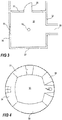
- a monitoring camera 10 is installed in the ceiling of a room 30, see Fig 3 .
- the room includes four walls 31-34, wherein wall 31 hold a door 36 for passage to an area next to the room, wall 32 present a passage into a corridor 38, and wall 34 hold a window 40.
- the monitoring camera 10 is set in an overview mode, i.e. the camera head is capturing an overview image of the monitored area, by capturing images through the wide angle lens, the setting of the camera that is shown in Fig 1 .
- a frame from a video sequence from the monitoring camera 10 in overview mode may look like the image in Fig 4 in which all four walls 31-34 of the monitored room 30 is captured by the overview camera view, i.e. the entire room 30 is captured by the monitoring camera when in overview mode. Moreover, the image frame reveals that a person 42 is entering the room. This is probably even more evident from a video sequence including the image frame.
- the operator may simply indicate the person 42 or the area of the person in the overview image at a control station and the camera head of the monitoring camera is directed away from the wide angle lens 20 and towards the indicated area of the monitored room 30.
- the directing of the camera head 12 away from the wide angle lens 20 may alternatively be initiated in response to a detected motion in the overview image, detected by means of a motion detection process.
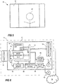
- the camera head 12 will be moved into a position similar to the position showed in Fig 2 , and will possibly capture an image 44 as the one presented in Fig 5 .
- the image captured by the camera head 12 may have a wider or narrower image view depending on the lens 18 on the camera head 12 and/or the zoom setting of this lens 18. Then, when the operator has finished studying the person the camera head 12 may be returned to capture images through the wide angle lens 20 and thereby be returned to the overview mode of the monitoring camera. Alternatively, if the directing of the camera head 12 away from the wide angle lens 20 was performed in response to motion detection in the overview image, then the camera head 12 may return to capturing images through the wide angle lens 20 in response to no motion being detected in the detailed view.
- the monitoring camera 10 includes an image sensor 50, an image processing unit 52, a general processing unit 54, a volatile memory 56, a non-volatile memory 58, a network interface 60, a camera position controller 61, a panning motor 62, a panning motor controller 64, a tilting motor 66, and a tilting motor controller 68. Further means and devices required in a camera in order to perform normal camera functionality and normal network activities are not described herein as these means and devices are well known to the person skilled in the art.
- the image sensor 50 may be any known image sensor able to capture light representing an image view and convert the light to electrical signals which then may be processed into digital images and or digital image streams by the image processing unit 52.
- the image sensor 50 may be arranged to capture visible light or infrared light, depending on the application of the camera.
- the image data from the image sensor 50 is sent to the image processing unit 52 via connection 70.
- the image processing unit 52 and the general processing unit 54 may be the same device, may be implemented as separate units on the same chip, or may be separate devices. Moreover, many functions described below as being performed in the image processing unit 52 may be performed in the general processing unit 54 and vice versa.
- the processing units 52, 54 are connected to the volatile memory 56 for use as a work memory via for instance a bus 72. Moreover, the volatile memory 56 may be used as temporary data storage for image data during processing of the image data and the volatile memory 56 may therefore be connected to the image sensor 50 as well.
- the non-volatile memory 58 may store program code required for the processing units 52, 54 to operate and may store settings and parameters that is to be preserved for a longer time period and even withstand power outages.
- the processing units 52, 54 are connected to the non-volatile memory 58 via, for instance, the bus 72.
- the network interface 60 includes an electrical interface to the network 74, which the monitoring camera is to be connected to. Further, the network interface 60 also includes all logic interface parts that are not implemented as being executed by the processing unit 54.
- the network 74 may be any known type of LAN (Local Area Network), WAN (Wide Area Network), or the Internet. The person skilled in the art is well aware of how to implement a network interface using any of a plurality of known implementations and protocols.
- the panning motor 62 and the tilting motor 66 are controlled by the processing 54 unit via each motor controller 64, 68.
- the motor controllers are arranged to convert instructions from the camera position controller 61 into electrical signals compatible with the motors.
- the camera position controller 61 may be implemented by means of code stored in memory 58 or by logical circuitry.
- the tilt motor 66 may be arranged within or very close to a panable/tiltable camera head 12 and the pan motor 62 are in many cases arranged further away from the camera head 12, in particular in the cases where the joint for panning is the second joint, counted from the camera head 12. Control messages for pan and tilt may be received via the network 74 and processed by the processing unit 54 before forwarded to the motor controllers 64, 68.
- the monitoring camera 10 may be remotely operated from a surveillance centre, from a simple computer setup including a personal computer, a work station, or similar equipment, from a telephone or any other small handset.
- remotely operated we mean that it may be operated from a remote location 76 at any distance from the monitoring camera 10, e.g. being operated from a room next to the monitoring camera 10 or from another country.
- the monitoring camera 10 is connected to a monitoring controller 78 arranged at a remote location 76.
- the monitoring camera 10 and the monitoring controller 78 are connecting to each other via the network 74, described above.
- the monitoring camera 10 may be remotely operated using a control means 80, e.g. a joy stick, a track ball, a mouse, a touch pad, etc., connected to the monitoring controller 78 and the imagery from the monitoring camera 10 may be viewed on a display device 82, e.g. a monitor, a display on a handheld device etc.
- the monitoring controller 78 may be any computer device arranged to connect to a monitoring camera 10 over the network 74, to provide monitoring images to the display device 82, and to receive control signals from the control means 80.
- a live overview image 84 i.e. a real time moving picture continuously captured by the camera head 12 through the wide angle lens 20
- the operator may be interested in leaving the overview in order to manoeuvre the camera 10 in detailed mode due to something he observes in the overview image 84 or in order to take a closer look at something.
- the term moving picture is to be interpreted as an image view represented by frequently updated images presented in a temporal order with moving objects shown in successive positions slightly changed so as to produce the optical effect of a continuous picture in which the moving objects move.
- the directional control means 80 used today are implementing normal pan tilt control functions. This normal control function transforms right and left movement of the control means 80 to right and left panning of the camera head 12 and it transforms forward and back movement of the control means 80 to up and down tilting. This normal control function is used independently of whether the monitoring system is in overview mode or in detailed mode.
- the system when in overview mode is arranged to respond to a control means 80 movement, which may be translated to a direction, by exiting the overview mode and directing the monitoring camera 10 in an absolute direction corresponding to the direction of the movement of the control means 80.
- a control means 80 movement which may be translated to a direction
- the absolute direction having the angle ⁇ in the overview image of Fig 8 corresponds to the moving angle ⁇ of the joystick in Fig 9 .
- the polar coordinate systems are shown in Figs 8 and 9 in which the dash dotted lines represents 0, 90, 180, and 270 degrees, in the polar coordinate system.
- the direction angle ⁇ may then be sent in a pan command to the monitoring camera 10 in order to make the monitoring camera 10 pan into the requested direction, i.e. to the requested pan angle ⁇ .
- This will only work if the polar coordinate systems of the overview 84 and the control means 80 corresponds to the same angles in a pan control system controlling the panning of the monitoring camera 10, i.e. if the corridor of the overview corresponds to pan angle 0°, the door correspond to pan angle 90°, and the window correspond to pan angle 180°.
- a correction constant ⁇ may be applied to a transfer function generating the pan angle corresponding to a specified direction in the overview image.
- the tilt angle of the camera head 12 may be set to a predetermined tilt angle ⁇ pre .
- This predetermined tilt angle ⁇ pre may be selected for providing as much environmental information as possible from the position of the selected pan angle ⁇ .
- the predetermined tilt angle ⁇ pre is set to an angle that is close to the edge of the wide angle lens 20, without having any part of the wide angle lens 20 obscuring the image view captured by the camera head 12.
- the camera head 12 does not have to tilt very far and, thus, the time it takes to arrive at the correct tilt angle ⁇ pre is short.
- the operator knows that he have to tilt the camera 10 in one specific direction if the desired camera view is not captured initially.
- the predetermined tilt angle is 45 degrees.
- the control function transforming control means 80 movements to movement of the camera head 12 is switched to the normal pan tilt control function mentioned above.
- This control function does not make any sense for an operator when the camera is in overview mode as a right/left movement of the control means then only will make the overview image spin around.
- the monitoring camera 10 according to one embodiment of the invention is moving according to an overview mode control scheme when in overview mode and according to a detailed mode control scheme.
- a flowchart describes a method, according to one embodiment of the invention, for switching from the overview mode to the detailed mode.
- the process described below is performed in the monitoring camera 10.
- One specific advantage of performing the process in the monitoring camera 10 is that a camera implementing this method will be compatible with existing monitoring software because the same control signals as for existing systems may be sent to the camera. Hence, the monitoring software and the rest of the monitoring system do not need to know that the monitoring camera 10 operates differently. However, it is possible to perform the process in a device separate from the monitoring camera 10 and transmit only control instructions to the monitoring camera 10.
- This process starts when the monitoring camera 10 is in overview mode and its movements is controlled in accordance with an overview control scheme and in order to start the switching process a control signal including an indication of the direction of the movement of a control means 80 is received, step 102.
- the angular direction of the movement of the control means 80 is determined from the control signal received from the control means 80, step 104.
- a pan angle ⁇ is calculated based on said angular direction, step 106.
- a control signal representing the resulting pan angle ⁇ is sent to a panning motor 62 for turning the camera head 12 to the calculated pan angle ⁇ , step 108.
- a control signal representing a predetermined tilt angle ⁇ pre is sent to a tilting motor 66, step 110.
- the monitoring camera 10 is switched from overview mode to detailed mode and the camera movement control scheme is changed to a detailed mode control scheme, step 112, in which right movement of control means 80 translates to clockwise panning of camera head, left movement of control means translates to counter clockwise panning of camera head 12, forward movement of control means 80 translates to upwards, in relation to the image presented on the display device, tilting of camera head 12, and downward movement of control means 80 translates to downwards, in relation to the image presented on the display device, tilting of camera head 12.
- the method according to the invention may be implemented as a program code that is stored in a memory 56, 58, processed by a processor 54.
- the memory 56, 58, and processor 54 may be a processer and a memory of the monitoring camera 10 itself, of the monitoring controller 78, or any other computing device of a monitoring system.
- the method may be implemented by a purpose designed hard coded or hard wired system.
Claims (8)
- Procédé de commutation de fonctionnement d'un système de surveillance d'un premier mode de surveillance à un second mode de surveillance, le système de surveillance comprenant une caméra (10) comprenant une base de caméra (16), une tête de caméra à fonction panoramique et d'inclinaison (12) et un moyen de commande (80) pour un opérateur, le procédé comprenant de :présenter une image de vue d'ensemble (84) lorsque le système de surveillance est dans ledit premier mode de surveillance dans lequel l'image de vue d'ensemble capturée lorsque le système de surveillance est dans le premier mode de surveillance est capturée au moyen de la tête de caméra à fonction panoramique et d'inclinaison (12) par l'intermédiaire d'un objectif grand angle (20) qui est disposé de manière fixe par rapport à la base de caméra (16),répondre, lorsque le système de surveillance est dans ledit premier mode de surveillance, à un mouvement de direction du moyen de commande (80) configuré pour effectuer un balayage horizontal et vertical avec la tête de caméra à fonction panoramique et d'inclinaison (12) en traduisant le mouvement de direction du moyen de commande (80) en un signal de direction,diriger la tête de caméra à fonction de panoramique et d'inclinaison (12) dans une direction absolue indiquée par ledit signal de direction conformément à un mécanisme de commande de mouvement de caméra étant un premier mécanisme de commande de caméra, dans lequel la direction absolue correspond à la direction du mouvement du moyen de commande (80),faire entrer le système de surveillance dans ledit second mode de surveillance en réponse à la réception dudit signal de direction,présenter une vue d'images détaillée capturée par la caméra (10) lorsqu'elle est dirigée dans la direction indiquée par ledit signal de direction, dans lequel l'image détaillée capturée lorsque le système de surveillance est dans le second mode de surveillance est capturée au moyen de la tête de caméra (12) n'étant pas dirigée à travers l'objectif grand angle (20), etdéplacer, lorsque dans le second mode de surveillance, la tête de caméra (12) de la caméra (10) en réponse aux signaux de commande provenant du moyen de commande (80) conformément à un second mécanisme de commande.
- Procédé selon la revendication 1, dans lequel l'image de vue d'ensemble présentée (84) et la vue d'image détaillée présentée, respectivement, sont capturées et présentées comme des images animées.
- Procédé selon une quelconque des revendications 1-2, dans lequel le système de surveillance inclut un capteur d'image (50) et dans lequel l'action de capture d'image présentée est effectuée par le même capteur d'image (50) indépendamment du fait que le système de surveillance est dans ledit premier mode de surveillance ou dans ledit second mode de surveillance.
- Procédé selon une quelconque des revendications 1-3, comprenant en outre de transformer une information de signal de direction provenant du moyen de commande (80) en une direction angulaire (α).
- Procédé selon la revendication 4, dans lequel la direction de mouvement du moyen de commande (80) transforme la direction angulaire correspondante (α) en l'image de vue d'ensemble (84).
- Procédé selon la revendication 4 ou 5, dans lequel la transformation d'information dudit signal de direction provenant du moyen de commande (80) en une direction angulaire (α) inclut de transformer le signal en un angle de contrôleur correspondant à la direction de mouvement du moyen de commande (80) et d'additionner un angle d'ajustement à l'angle de contrôleur afin de compenser n'importe quel écart des directions de référence angulaire entre le signal de direction provenant du moyen de commande (80) et les angles de panoramique de la caméra (10).
- Procédé selon une quelconque des revendications 1-6, dans lequel la direction de la caméra (10) inclut de tourner la tête de caméra (12) à un angle de panoramique correspondant à un angle indiqué par le signal de direction du moyen de commande (80).
- Procédé selon la revendication 7, dans lequel la direction de la caméra (10) comprend en outre de tourner la tête de caméra (12) à un angle d'inclinaison préréglé (ϕpre ).
Priority Applications (3)
| Application Number | Priority Date | Filing Date | Title |
|---|---|---|---|
| EP12163178.2A EP2648406B1 (fr) | 2012-04-04 | 2012-04-04 | Procédé de changement de mode vidéo dans une caméra |
| US13/835,740 US9729835B2 (en) | 2012-04-04 | 2013-03-15 | Method for switching viewing modes in a camera |
| CN201310097048.4A CN103369237B (zh) | 2012-04-04 | 2013-03-25 | 用于切换相机观察模式的方法 |
Applications Claiming Priority (1)
| Application Number | Priority Date | Filing Date | Title |
|---|---|---|---|
| EP12163178.2A EP2648406B1 (fr) | 2012-04-04 | 2012-04-04 | Procédé de changement de mode vidéo dans une caméra |
Publications (2)
| Publication Number | Publication Date |
|---|---|
| EP2648406A1 EP2648406A1 (fr) | 2013-10-09 |
| EP2648406B1 true EP2648406B1 (fr) | 2018-08-22 |
Family
ID=46026639
Family Applications (1)
| Application Number | Title | Priority Date | Filing Date |
|---|---|---|---|
| EP12163178.2A Active EP2648406B1 (fr) | 2012-04-04 | 2012-04-04 | Procédé de changement de mode vidéo dans une caméra |
Country Status (3)
| Country | Link |
|---|---|
| US (1) | US9729835B2 (fr) |
| EP (1) | EP2648406B1 (fr) |
| CN (1) | CN103369237B (fr) |
Families Citing this family (6)
| Publication number | Priority date | Publication date | Assignee | Title |
|---|---|---|---|---|
| CN103533309A (zh) * | 2013-10-18 | 2014-01-22 | 中国民用航空总局第二研究所 | 可同时进行全景显示与局部查看的方法及分布式联动系统 |
| US10334150B2 (en) | 2014-05-14 | 2019-06-25 | Hanwha Aerospace Co., Ltd. | Camera system and method of tracking object using the same |
| CN105391975A (zh) * | 2015-11-02 | 2016-03-09 | 中国民用航空总局第二研究所 | 一种场面监视中的视频处理方法、装置及场面监视系统 |
| US10580121B2 (en) * | 2017-11-16 | 2020-03-03 | Axis Ab | Image noise reduction based on a modulation transfer function of a camera dome |
| CN111343377A (zh) * | 2018-12-19 | 2020-06-26 | 杭州海康威视系统技术有限公司 | 摄像机控制方法、装置、系统及存储介质 |
| EP3829159A1 (fr) * | 2019-11-29 | 2021-06-02 | Ricoh Company, Ltd. | Dispositif de capture d'image, système de communication et procédé de commande d'affichage et support |
Citations (1)
| Publication number | Priority date | Publication date | Assignee | Title |
|---|---|---|---|---|
| EP2187622A1 (fr) * | 2008-11-12 | 2010-05-19 | Axis AB | Ensemble caméra |
Family Cites Families (16)
| Publication number | Priority date | Publication date | Assignee | Title |
|---|---|---|---|---|
| EP0715453B1 (fr) * | 1994-11-28 | 2014-03-26 | Canon Kabushiki Kaisha | Dispositif de commande pour caméra |
| EP0878965A3 (fr) | 1997-05-14 | 2000-01-12 | Hitachi Denshi Kabushiki Kaisha | Méthode pour la poursuite d'un objet entrant et appareil pour la poursuite et la surveillance d'un tel objet |
| US6215519B1 (en) * | 1998-03-04 | 2001-04-10 | The Trustees Of Columbia University In The City Of New York | Combined wide angle and narrow angle imaging system and method for surveillance and monitoring |
| US6226035B1 (en) * | 1998-03-04 | 2001-05-01 | Cyclo Vision Technologies, Inc. | Adjustable imaging system with wide angle capability |
| US6532035B1 (en) * | 2000-06-29 | 2003-03-11 | Nokia Mobile Phones Ltd. | Method and apparatus for implementation of close-up imaging capability in a mobile imaging system |
| GB2368221A (en) * | 2000-08-31 | 2002-04-24 | Lee Scott Friend | Camera apparatus having both omnidirectional and normal view imaging modes. |
| US7173650B2 (en) * | 2001-03-28 | 2007-02-06 | Koninklijke Philips Electronics N.V. | Method for assisting an automated video tracking system in reaquiring a target |
| JP4568009B2 (ja) * | 2003-04-22 | 2010-10-27 | パナソニック株式会社 | カメラ連携による監視装置 |
| US7990422B2 (en) * | 2004-07-19 | 2011-08-02 | Grandeye, Ltd. | Automatically expanding the zoom capability of a wide-angle video camera |
| JP2007243268A (ja) * | 2006-03-06 | 2007-09-20 | Sony Corp | 映像監視システムおよび映像監視プログラム |
| US7755697B2 (en) * | 2007-03-28 | 2010-07-13 | Logitech Europe S.A. | Webcam with moveable zoom lens |
| EP1981263B1 (fr) * | 2007-04-13 | 2019-04-03 | Axis AB | Prise en charge de la rotation panoramique continue dans une caméra à panoramique/inclinaison |
| CN101119478A (zh) | 2007-05-09 | 2008-02-06 | 上海天卫通信科技有限公司 | 双镜头视频监控中的视角自动配置系统和方法 |
| MY164862A (en) * | 2007-11-22 | 2018-01-30 | Mimos Berhad | Device and method for a surveillance system |
| EP2449760A1 (fr) * | 2009-06-29 | 2012-05-09 | Bosch Security Systems, Inc. | Procédé et système de caméra de surveillance de type dôme, intelligente, omnidirectionnelle pour la reconnaissance situationnelle et environnementale |
| JP5643552B2 (ja) * | 2010-06-28 | 2014-12-17 | キヤノン株式会社 | 撮像装置 |
-
2012
- 2012-04-04 EP EP12163178.2A patent/EP2648406B1/fr active Active
-
2013
- 2013-03-15 US US13/835,740 patent/US9729835B2/en active Active
- 2013-03-25 CN CN201310097048.4A patent/CN103369237B/zh active Active
Patent Citations (1)
| Publication number | Priority date | Publication date | Assignee | Title |
|---|---|---|---|---|
| EP2187622A1 (fr) * | 2008-11-12 | 2010-05-19 | Axis AB | Ensemble caméra |
Also Published As
| Publication number | Publication date |
|---|---|
| US9729835B2 (en) | 2017-08-08 |
| CN103369237B (zh) | 2018-08-21 |
| EP2648406A1 (fr) | 2013-10-09 |
| CN103369237A (zh) | 2013-10-23 |
| US20130265436A1 (en) | 2013-10-10 |
Similar Documents
| Publication | Publication Date | Title |
|---|---|---|
| EP2648406B1 (fr) | Procédé de changement de mode vidéo dans une caméra | |
| TWI422218B (zh) | Control devices, camera systems and programs for monitoring camera systems | |
| EP1619897B1 (fr) | Système d'appareil-photo en ligne, dispositif d'appareil-photo et méthode de contrôle d'appareil-photo en ligne | |
| US20070115355A1 (en) | Methods and apparatus for operating a pan tilt zoom camera | |
| US10917560B2 (en) | Control apparatus, movable apparatus, and remote-control system | |
| US20120019664A1 (en) | Control apparatus for auto-tracking camera system and auto-tracking camera system equipped with same | |
| US20130314547A1 (en) | Controlling apparatus for automatic tracking camera, and automatic tracking camera having the same | |
| JP4243883B2 (ja) | リモコン雲台システム | |
| JP2017062529A (ja) | 方向制御方法 | |
| US20060256201A1 (en) | Methods and systems for controlling camera movement | |
| JP6624800B2 (ja) | 画像処理装置、画像処理方法、及び画像処理システム | |
| US8692879B2 (en) | Image capturing system, image capturing device, information processing device, and image capturing method | |
| US9386280B2 (en) | Method for setting up a monitoring camera | |
| KR101452342B1 (ko) | 감시카메라 유닛 및 그 구동방법 | |
| US11700454B2 (en) | Image capturing control apparatus, image capturing control method, and non-transitory computer-readable storage medium | |
| JP2009301175A (ja) | 監視方法 | |
| CN103902028B (zh) | 输入设备、交互系统和输入方法 | |
| JPH11331824A (ja) | カメラ動作制御装置 | |
| JPS6231272A (ja) | 雲台制御装置 | |
| KR200481796Y1 (ko) | Ptz 카메라 컨트롤러 | |
| JP2017216536A (ja) | カメラ制御システム | |
| JPH10257375A (ja) | 撮像装置および撮像方法 | |
| JP2019140566A (ja) | 情報処理装置、情報処理方法及びプログラム | |
| JPH07274150A (ja) | 遠隔カメラ操作機能を有するテレビ会議装置 | |
| JP2007068068A (ja) | 遠隔監視システム |
Legal Events
| Date | Code | Title | Description |
|---|---|---|---|
| PUAI | Public reference made under article 153(3) epc to a published international application that has entered the european phase |
Free format text: ORIGINAL CODE: 0009012 |
|
| AK | Designated contracting states |
Kind code of ref document: A1 Designated state(s): AL AT BE BG CH CY CZ DE DK EE ES FI FR GB GR HR HU IE IS IT LI LT LU LV MC MK MT NL NO PL PT RO RS SE SI SK SM TR |
|
| AX | Request for extension of the european patent |
Extension state: BA ME |
|
| 17P | Request for examination filed |
Effective date: 20140408 |
|
| RBV | Designated contracting states (corrected) |
Designated state(s): AL AT BE BG CH CY CZ DE DK EE ES FI FR GB GR HR HU IE IS IT LI LT LU LV MC MK MT NL NO PL PT RO RS SE SI SK SM TR |
|
| STAA | Information on the status of an ep patent application or granted ep patent |
Free format text: STATUS: EXAMINATION IS IN PROGRESS |
|
| 17Q | First examination report despatched |
Effective date: 20170117 |
|
| GRAP | Despatch of communication of intention to grant a patent |
Free format text: ORIGINAL CODE: EPIDOSNIGR1 |
|
| STAA | Information on the status of an ep patent application or granted ep patent |
Free format text: STATUS: GRANT OF PATENT IS INTENDED |
|
| RIC1 | Information provided on ipc code assigned before grant |
Ipc: H04N 7/18 20060101AFI20180517BHEP Ipc: G02B 13/06 20060101ALI20180517BHEP Ipc: G02B 15/10 20060101ALI20180517BHEP Ipc: H04N 5/232 20060101ALI20180517BHEP |
|
| INTG | Intention to grant announced |
Effective date: 20180606 |
|
| GRAS | Grant fee paid |
Free format text: ORIGINAL CODE: EPIDOSNIGR3 |
|
| GRAA | (expected) grant |
Free format text: ORIGINAL CODE: 0009210 |
|
| STAA | Information on the status of an ep patent application or granted ep patent |
Free format text: STATUS: THE PATENT HAS BEEN GRANTED |
|
| AK | Designated contracting states |
Kind code of ref document: B1 Designated state(s): AL AT BE BG CH CY CZ DE DK EE ES FI FR GB GR HR HU IE IS IT LI LT LU LV MC MK MT NL NO PL PT RO RS SE SI SK SM TR |
|
| REG | Reference to a national code |
Ref country code: GB Ref legal event code: FG4D |
|
| REG | Reference to a national code |
Ref country code: CH Ref legal event code: EP |
|
| REG | Reference to a national code |
Ref country code: AT Ref legal event code: REF Ref document number: 1033861 Country of ref document: AT Kind code of ref document: T Effective date: 20180915 |
|
| REG | Reference to a national code |
Ref country code: SE Ref legal event code: TRGR |
|
| REG | Reference to a national code |
Ref country code: IE Ref legal event code: FG4D |
|
| REG | Reference to a national code |
Ref country code: DE Ref legal event code: R096 Ref document number: 602012049989 Country of ref document: DE |
|
| REG | Reference to a national code |
Ref country code: NL Ref legal event code: MP Effective date: 20180822 |
|
| REG | Reference to a national code |
Ref country code: LT Ref legal event code: MG4D |
|
| PG25 | Lapsed in a contracting state [announced via postgrant information from national office to epo] |
Ref country code: LT Free format text: LAPSE BECAUSE OF FAILURE TO SUBMIT A TRANSLATION OF THE DESCRIPTION OR TO PAY THE FEE WITHIN THE PRESCRIBED TIME-LIMIT Effective date: 20180822 Ref country code: RS Free format text: LAPSE BECAUSE OF FAILURE TO SUBMIT A TRANSLATION OF THE DESCRIPTION OR TO PAY THE FEE WITHIN THE PRESCRIBED TIME-LIMIT Effective date: 20180822 Ref country code: NL Free format text: LAPSE BECAUSE OF FAILURE TO SUBMIT A TRANSLATION OF THE DESCRIPTION OR TO PAY THE FEE WITHIN THE PRESCRIBED TIME-LIMIT Effective date: 20180822 Ref country code: BG Free format text: LAPSE BECAUSE OF FAILURE TO SUBMIT A TRANSLATION OF THE DESCRIPTION OR TO PAY THE FEE WITHIN THE PRESCRIBED TIME-LIMIT Effective date: 20181122 Ref country code: FI Free format text: LAPSE BECAUSE OF FAILURE TO SUBMIT A TRANSLATION OF THE DESCRIPTION OR TO PAY THE FEE WITHIN THE PRESCRIBED TIME-LIMIT Effective date: 20180822 Ref country code: GR Free format text: LAPSE BECAUSE OF FAILURE TO SUBMIT A TRANSLATION OF THE DESCRIPTION OR TO PAY THE FEE WITHIN THE PRESCRIBED TIME-LIMIT Effective date: 20181123 Ref country code: NO Free format text: LAPSE BECAUSE OF FAILURE TO SUBMIT A TRANSLATION OF THE DESCRIPTION OR TO PAY THE FEE WITHIN THE PRESCRIBED TIME-LIMIT Effective date: 20181122 Ref country code: IS Free format text: LAPSE BECAUSE OF FAILURE TO SUBMIT A TRANSLATION OF THE DESCRIPTION OR TO PAY THE FEE WITHIN THE PRESCRIBED TIME-LIMIT Effective date: 20181222 |
|
| REG | Reference to a national code |
Ref country code: AT Ref legal event code: MK05 Ref document number: 1033861 Country of ref document: AT Kind code of ref document: T Effective date: 20180822 |
|
| PG25 | Lapsed in a contracting state [announced via postgrant information from national office to epo] |
Ref country code: LV Free format text: LAPSE BECAUSE OF FAILURE TO SUBMIT A TRANSLATION OF THE DESCRIPTION OR TO PAY THE FEE WITHIN THE PRESCRIBED TIME-LIMIT Effective date: 20180822 Ref country code: HR Free format text: LAPSE BECAUSE OF FAILURE TO SUBMIT A TRANSLATION OF THE DESCRIPTION OR TO PAY THE FEE WITHIN THE PRESCRIBED TIME-LIMIT Effective date: 20180822 Ref country code: AL Free format text: LAPSE BECAUSE OF FAILURE TO SUBMIT A TRANSLATION OF THE DESCRIPTION OR TO PAY THE FEE WITHIN THE PRESCRIBED TIME-LIMIT Effective date: 20180822 |
|
| PG25 | Lapsed in a contracting state [announced via postgrant information from national office to epo] |
Ref country code: RO Free format text: LAPSE BECAUSE OF FAILURE TO SUBMIT A TRANSLATION OF THE DESCRIPTION OR TO PAY THE FEE WITHIN THE PRESCRIBED TIME-LIMIT Effective date: 20180822 Ref country code: IT Free format text: LAPSE BECAUSE OF FAILURE TO SUBMIT A TRANSLATION OF THE DESCRIPTION OR TO PAY THE FEE WITHIN THE PRESCRIBED TIME-LIMIT Effective date: 20180822 Ref country code: CZ Free format text: LAPSE BECAUSE OF FAILURE TO SUBMIT A TRANSLATION OF THE DESCRIPTION OR TO PAY THE FEE WITHIN THE PRESCRIBED TIME-LIMIT Effective date: 20180822 Ref country code: EE Free format text: LAPSE BECAUSE OF FAILURE TO SUBMIT A TRANSLATION OF THE DESCRIPTION OR TO PAY THE FEE WITHIN THE PRESCRIBED TIME-LIMIT Effective date: 20180822 Ref country code: AT Free format text: LAPSE BECAUSE OF FAILURE TO SUBMIT A TRANSLATION OF THE DESCRIPTION OR TO PAY THE FEE WITHIN THE PRESCRIBED TIME-LIMIT Effective date: 20180822 Ref country code: ES Free format text: LAPSE BECAUSE OF FAILURE TO SUBMIT A TRANSLATION OF THE DESCRIPTION OR TO PAY THE FEE WITHIN THE PRESCRIBED TIME-LIMIT Effective date: 20180822 Ref country code: PL Free format text: LAPSE BECAUSE OF FAILURE TO SUBMIT A TRANSLATION OF THE DESCRIPTION OR TO PAY THE FEE WITHIN THE PRESCRIBED TIME-LIMIT Effective date: 20180822 |
|
| REG | Reference to a national code |
Ref country code: DE Ref legal event code: R097 Ref document number: 602012049989 Country of ref document: DE |
|
| PG25 | Lapsed in a contracting state [announced via postgrant information from national office to epo] |
Ref country code: SK Free format text: LAPSE BECAUSE OF FAILURE TO SUBMIT A TRANSLATION OF THE DESCRIPTION OR TO PAY THE FEE WITHIN THE PRESCRIBED TIME-LIMIT Effective date: 20180822 Ref country code: SM Free format text: LAPSE BECAUSE OF FAILURE TO SUBMIT A TRANSLATION OF THE DESCRIPTION OR TO PAY THE FEE WITHIN THE PRESCRIBED TIME-LIMIT Effective date: 20180822 Ref country code: DK Free format text: LAPSE BECAUSE OF FAILURE TO SUBMIT A TRANSLATION OF THE DESCRIPTION OR TO PAY THE FEE WITHIN THE PRESCRIBED TIME-LIMIT Effective date: 20180822 |
|
| PLBE | No opposition filed within time limit |
Free format text: ORIGINAL CODE: 0009261 |
|
| STAA | Information on the status of an ep patent application or granted ep patent |
Free format text: STATUS: NO OPPOSITION FILED WITHIN TIME LIMIT |
|
| 26N | No opposition filed |
Effective date: 20190523 |
|
| PG25 | Lapsed in a contracting state [announced via postgrant information from national office to epo] |
Ref country code: SI Free format text: LAPSE BECAUSE OF FAILURE TO SUBMIT A TRANSLATION OF THE DESCRIPTION OR TO PAY THE FEE WITHIN THE PRESCRIBED TIME-LIMIT Effective date: 20180822 |
|
| REG | Reference to a national code |
Ref country code: CH Ref legal event code: PL |
|
| REG | Reference to a national code |
Ref country code: BE Ref legal event code: MM Effective date: 20190430 |
|
| PG25 | Lapsed in a contracting state [announced via postgrant information from national office to epo] |
Ref country code: MC Free format text: LAPSE BECAUSE OF FAILURE TO SUBMIT A TRANSLATION OF THE DESCRIPTION OR TO PAY THE FEE WITHIN THE PRESCRIBED TIME-LIMIT Effective date: 20180822 Ref country code: LU Free format text: LAPSE BECAUSE OF NON-PAYMENT OF DUE FEES Effective date: 20190404 |
|
| PG25 | Lapsed in a contracting state [announced via postgrant information from national office to epo] |
Ref country code: LI Free format text: LAPSE BECAUSE OF NON-PAYMENT OF DUE FEES Effective date: 20190430 Ref country code: CH Free format text: LAPSE BECAUSE OF NON-PAYMENT OF DUE FEES Effective date: 20190430 |
|
| PG25 | Lapsed in a contracting state [announced via postgrant information from national office to epo] |
Ref country code: BE Free format text: LAPSE BECAUSE OF NON-PAYMENT OF DUE FEES Effective date: 20190430 |
|
| PG25 | Lapsed in a contracting state [announced via postgrant information from national office to epo] |
Ref country code: TR Free format text: LAPSE BECAUSE OF FAILURE TO SUBMIT A TRANSLATION OF THE DESCRIPTION OR TO PAY THE FEE WITHIN THE PRESCRIBED TIME-LIMIT Effective date: 20180822 |
|
| PG25 | Lapsed in a contracting state [announced via postgrant information from national office to epo] |
Ref country code: IE Free format text: LAPSE BECAUSE OF NON-PAYMENT OF DUE FEES Effective date: 20190404 |
|
| PG25 | Lapsed in a contracting state [announced via postgrant information from national office to epo] |
Ref country code: PT Free format text: LAPSE BECAUSE OF FAILURE TO SUBMIT A TRANSLATION OF THE DESCRIPTION OR TO PAY THE FEE WITHIN THE PRESCRIBED TIME-LIMIT Effective date: 20181222 |
|
| PG25 | Lapsed in a contracting state [announced via postgrant information from national office to epo] |
Ref country code: CY Free format text: LAPSE BECAUSE OF FAILURE TO SUBMIT A TRANSLATION OF THE DESCRIPTION OR TO PAY THE FEE WITHIN THE PRESCRIBED TIME-LIMIT Effective date: 20180822 |
|
| PG25 | Lapsed in a contracting state [announced via postgrant information from national office to epo] |
Ref country code: HU Free format text: LAPSE BECAUSE OF FAILURE TO SUBMIT A TRANSLATION OF THE DESCRIPTION OR TO PAY THE FEE WITHIN THE PRESCRIBED TIME-LIMIT; INVALID AB INITIO Effective date: 20120404 Ref country code: MT Free format text: LAPSE BECAUSE OF FAILURE TO SUBMIT A TRANSLATION OF THE DESCRIPTION OR TO PAY THE FEE WITHIN THE PRESCRIBED TIME-LIMIT Effective date: 20180822 |
|
| PG25 | Lapsed in a contracting state [announced via postgrant information from national office to epo] |
Ref country code: MK Free format text: LAPSE BECAUSE OF FAILURE TO SUBMIT A TRANSLATION OF THE DESCRIPTION OR TO PAY THE FEE WITHIN THE PRESCRIBED TIME-LIMIT Effective date: 20180822 |
|
| PGFP | Annual fee paid to national office [announced via postgrant information from national office to epo] |
Ref country code: FR Payment date: 20230321 Year of fee payment: 12 |
|
| PGFP | Annual fee paid to national office [announced via postgrant information from national office to epo] |
Ref country code: SE Payment date: 20230327 Year of fee payment: 12 |
|
| P01 | Opt-out of the competence of the unified patent court (upc) registered |
Effective date: 20230505 |
|
| PGFP | Annual fee paid to national office [announced via postgrant information from national office to epo] |
Ref country code: DE Payment date: 20230321 Year of fee payment: 12 |
|
| PGFP | Annual fee paid to national office [announced via postgrant information from national office to epo] |
Ref country code: GB Payment date: 20240320 Year of fee payment: 13 |