EP2647108B1 - Verfahren zum prägen von spulenseiten einer ständerwicklung - Google Patents
Verfahren zum prägen von spulenseiten einer ständerwicklung Download PDFInfo
- Publication number
- EP2647108B1 EP2647108B1 EP11788846.1A EP11788846A EP2647108B1 EP 2647108 B1 EP2647108 B1 EP 2647108B1 EP 11788846 A EP11788846 A EP 11788846A EP 2647108 B1 EP2647108 B1 EP 2647108B1
- Authority
- EP
- European Patent Office
- Prior art keywords
- coil sides
- row
- groove
- embossing
- slot
- Prior art date
- Legal status (The legal status is an assumption and is not a legal conclusion. Google has not performed a legal analysis and makes no representation as to the accuracy of the status listed.)
- Active
Links
Images


Classifications
-
- H—ELECTRICITY
- H02—GENERATION; CONVERSION OR DISTRIBUTION OF ELECTRIC POWER
- H02K—DYNAMO-ELECTRIC MACHINES
- H02K15/00—Processes or apparatus specially adapted for manufacturing, assembling, maintaining or repairing of dynamo-electric machines
- H02K15/02—Processes or apparatus specially adapted for manufacturing, assembling, maintaining or repairing of dynamo-electric machines of stator or rotor bodies
- H02K15/021—Magnetic cores
-
- H—ELECTRICITY
- H02—GENERATION; CONVERSION OR DISTRIBUTION OF ELECTRIC POWER
- H02K—DYNAMO-ELECTRIC MACHINES
- H02K15/00—Processes or apparatus specially adapted for manufacturing, assembling, maintaining or repairing of dynamo-electric machines
- H02K15/04—Processes or apparatus specially adapted for manufacturing, assembling, maintaining or repairing of dynamo-electric machines of windings prior to their mounting into the machines
- H02K15/0414—Processes or apparatus specially adapted for manufacturing, assembling, maintaining or repairing of dynamo-electric machines of windings prior to their mounting into the machines the windings consisting of separate elements, e.g. bars, segments or half coils
- H02K15/0421—Processes or apparatus specially adapted for manufacturing, assembling, maintaining or repairing of dynamo-electric machines of windings prior to their mounting into the machines the windings consisting of separate elements, e.g. bars, segments or half coils and consisting of single conductors, e.g. hairpins
-
- H—ELECTRICITY
- H02—GENERATION; CONVERSION OR DISTRIBUTION OF ELECTRIC POWER
- H02K—DYNAMO-ELECTRIC MACHINES
- H02K3/00—Details of windings
- H02K3/04—Windings characterised by the conductor shape, form or construction, e.g. with bar conductors
-
- H—ELECTRICITY
- H02—GENERATION; CONVERSION OR DISTRIBUTION OF ELECTRIC POWER
- H02K—DYNAMO-ELECTRIC MACHINES
- H02K3/00—Details of windings
- H02K3/04—Windings characterised by the conductor shape, form or construction, e.g. with bar conductors
- H02K3/12—Windings characterised by the conductor shape, form or construction, e.g. with bar conductors arranged in slots
-
- Y—GENERAL TAGGING OF NEW TECHNOLOGICAL DEVELOPMENTS; GENERAL TAGGING OF CROSS-SECTIONAL TECHNOLOGIES SPANNING OVER SEVERAL SECTIONS OF THE IPC; TECHNICAL SUBJECTS COVERED BY FORMER USPC CROSS-REFERENCE ART COLLECTIONS [XRACs] AND DIGESTS
- Y10—TECHNICAL SUBJECTS COVERED BY FORMER USPC
- Y10T—TECHNICAL SUBJECTS COVERED BY FORMER US CLASSIFICATION
- Y10T29/00—Metal working
- Y10T29/49—Method of mechanical manufacture
- Y10T29/49002—Electrical device making
- Y10T29/49009—Dynamoelectric machine
Definitions
- the electrical fill factor ie the quotient of copper area to slot area
- Conventional stator manufacturing methods such as the feed method, allow values of 40% to a maximum of 50% electrical filling.
- the wires in the groove area can be densified by an embossing process, see for example WO-2001054254 A1 , This allows the range of more than 60% electrical filling in the stator slots to be achieved.
- certain constructive dependencies are taken into account (eg compact design of the winding heads, ...), more electrical power can be generated in a smaller volume with less material use.
- an embossed-material filling greater than 100% is established at the die.
- copper is displaced in the longitudinal direction of the wire in the winding heads and thus in the electromagnetically non-active region of the machine.
- the wire can not be embossed in an optimized way.
- the envelope shown in the figures represents the contour of the rows to be reached after forming.
- FIG. 1 is a longitudinal section through an electric machine 10, shown here in the embodiment as a generator or alternator for motor vehicles.
- This electrical machine 10 has, inter alia, a two-part housing 13, which consists of a first bearing plate 13.1 and a second bearing plate 13.2.
- the bearing plate 13.1 and the bearing plate 13.2 take in a so-called stator 16, on the one hand consists of a substantially annular stator iron 17, and in whose radially inwardly directed, axially extending grooves, a stator winding 18 is inserted.
- This annular stator 16 surrounds with its radially inwardly directed grooved surface a rotor 20 which is formed as a claw-pole rotor.
- the rotor 20 consists, inter alia, of two claw-pole plates 22 and 23, on whose outer circumference in each case axially extending claw-pole fingers 24 and 25 are arranged. Both claw-pole plates 22 and 23 are arranged in the rotor 20 such that their claw-pole fingers 24 and 25, which extend in the axial direction, alternate with one another on the circumference of the rotor 20. This results in magnetically required spaces between the oppositely magnetized claw pole fingers 24 and 25, which are referred to as Klauenpol formatschreib.
- the rotor 20 is rotatably supported in the respective end shields 13.1 and 13.2, respectively, by means of a shaft 27 and one respective rolling bearing 28 located on each side of the rotor.
- the rotor 20 has a total of two axial end faces, on each of which a fan 30 is attached.
- This fan 30 consists essentially of a plate-shaped or disc-shaped portion, emanating from the fan blades in a known manner.
- These fans 30 serve to allow an air exchange between the outside of the electric machine 10 and the interior of the electric machine 10 via openings 40 in the end shields 13.1 and 13.2.
- the openings 40 are provided essentially at the axial ends of the end shields 13.1 and 13.2, via which cooling air is sucked into the interior of the electric machine 10 by means of the fan 30.
- This cooling air is accelerated by the rotation of the fan 30 radially outward, so that they can pass through the cool air-permeable winding overhang 45 therethrough. By this effect, the winding overhang 45 is cooled.
- the cooling air takes after passing through the winding overhang 45 and after flowing around this winding overhang 45 a way radially outward, through here in this FIG. 1 not shown openings.
- this protective cap 47 covers, for example, a so-called slip ring assembly 49, which serves to supply a field winding 51 with exciter current.
- a heat sink 53 which acts as a positive heat sink here.
- the bearing plate acts 13.2.
- a connection plate 56 is arranged, which serves to connect arranged in the bearing plate 13.2 minus diodes 58 and not shown here in this illustration plus diodes in the heat sink 53 together and thus represent a known bridge circuit.
- FIG. 2 is a groove row 90 of round wires 93 and coil sides 96, which are to be formed parallel flank, shown.
- a method is provided for embossing a plurality of coil sides 96 for a stator winding 18, wherein the plurality of coil sides 96 are arranged in a groove row 90, being deformed with a force F whose direction of force has an angle ⁇ to the groove row 90 which is greater than zero is.
- the angle ⁇ is nearly or 90 °.
- the groove row 90 defines a direction in which the round wires 93 are stacked. The angle ⁇ starts from this direction.
- the forces F are aligned in such a way that they act diagonally through the groove row 90.
- the forces for example, on the one hand from the bottom of the groove bottom left and on the other hand act from the Nutschlitzseite top right.
- the forces F at an angle ⁇ > 45 ° act on each other.
- the considerations in this paragraph also apply to trapezoidal groove geometries.
- FIG. 4 When using trapezoidal groove geometries, FIG. 4 , even with a tangential embossing in a stamping chamber 102, problems similar to those of the radial embossing occur. In the upper narrow region of the embossing chamber 102, the deformations are not ideal, in the wide region of the groove 99 (bottom) also not ideal.
- stator windings or rows 90 of round wires 93 or coil sides 96 are embossed into two embossing chambers 102. Uniformly high mechanical filling in the chambers enables optimized electromagnetic designs to be implemented with electrical fill factors greater than 60%. In particular stator slot designs with trapezoidal groove shapes benefit from this principle.
- a method is provided, wherein the coil sides 96 are arranged in a plurality of sub-rows 110, wherein a plurality of sub-rows 110 form a groove row 90.
- FIGS. 6 and 7 a method is provided, wherein the coil sides 96 are arranged in several sub-rows 110, wherein a plurality of sub-rows 110 form a groove row 90 and per groove 99 a plurality of groove rows 90 are provided.
- the sub-rows 110 of a row of grooves 90 have a different number of coil sides 96.
- the sub-rows 110 are embossed in separate embossing chambers 102.
- Computational embossed groove fillings greater than 100% in partial areas of the groove are avoided with two embossing chambers. Impermissible deformations on individual wires no longer occur, no copper is displaced in the longitudinal direction (perpendicular to the plane of representation) into the electromagnetically non-active winding heads. That the calculated optimized design is actually used.
- interpretations with trapezoidal grooves can be implemented with two separate embossing chambers. Compensating movements between the narrow and wide area of the embossing chamber are not necessary. Difficult to control influences, such as the friction within the embossing chamber has no influence on the quality of execution. A restriction with respect to the groove shape is not present here, in particular different trapezoidal shapes are feasible.
- the proposed principle can be applied to different interpretations. It can be both single-row wire arrangements such as in a 5-phase system with 80 grooves (see FIG. 5 ), as well as double-row arrangements such as in a 3-phase system with 48 slots (see FIG. 6 ) will be realized. Further multi-row arrangements are conceivable in principle, the number of slots or the number of poles of the design are arbitrary. In addition, with an appropriate calculation of the embossing chamber surfaces, also designs with odd number of conductors can be built (see FIG. 7 ).
- the embossing in two chambers creates a clear and above all reproducible parting plane between Nutober- or -unterlage.
- Different conditions within the embossing groove such as e.g. Friction, wire strength or wire diameter have no influence on this parting plane.
- Friction e.g. Friction, wire strength or wire diameter have no influence on this parting plane.
- This can be of great advantage in subsequent process steps: for example, a setting process of the coil elements can take place along this parting plane.
- a stator is provided with a stator winding (18), which is manufactured according to one of the method steps presented here.
Landscapes
- Engineering & Computer Science (AREA)
- Power Engineering (AREA)
- Manufacturing & Machinery (AREA)
- Windings For Motors And Generators (AREA)
- Manufacture Of Motors, Generators (AREA)
Description
- Bei der Auslegung der Nutgeometrie im Ständereisen von elektrischen Maschinen ist der elektrische Füllfaktor d.h. der Quotient aus Kupferfläche zu Nutfläche ein entscheidender Parameter für die Beschreibung der Leistungsfähigkeit bzw. des Wirkungsgrades des Gesamtsystems. Übliche Ständer-Herstellverfahren, wie z.B. das Einzugsverfahren ermöglichen Werte von 40% bis maximal 50% elektrische Füllung.
Zur weiteren Steigerung dieser Werte können die Drähte im Nutbereich durch einen Prägevorgang verdichtet werden, siehe beispielsweiseWO-2001054254 A1 . Damit lässt sich der Bereich von über 60% elektrische Füllung in den Ständernuten erreichen. Vorausgesetzt bestimmte konstruktive Abhängigkeiten werden berücksichtigt (z.B. kompakte Ausführung der Wickelköpfe, ...), kann so mit weniger Materialeinsatz mehr elektrische Leistung in kleinerem Bauvolumen erzeugt werden. - Bei der technischen Umsetzung des Prägevorgangs sind bestimmte Randbedingungen von entscheidender Bedeutung: So können z.B. Drahtkreuzungen im Nutbereich zu Quetschungen mit stark reduziertem Querschnitt führen, die im Betrieb durch erhöhten ohmschen Widerstand zu lokalen Überhitzungen mit entsprechenden Folgen führen.
Hohe elektrische Füllfaktoren werden insbesondere durch hohe mechanische Füllung in den Prägewerkzeugen ermöglicht, deshalb wird unter Berücksichtigung der möglichen Drahttoleranzen eine Füllung der Prägenut nahe 100% angestrebt. Dies setzt allerdings voraus, dass alle Drähte im Nutbereich möglicht gleichmäßig verformt werden. - Bei ungünstiger Wahl der Prägerichtung ist diese Voraussetzung nicht erfüllt. Wird der Draht in radialer Richtung (in Nuthöhenrichtung) geprägt, so wird der Draht, welcher mit Kontakt zum Prägestempel hat, im Vergleich zum Draht im Prägenutgrund überproportional stark deformiert, weil sich der Prägedruck durch mechanische Reibung und andere Einflüsse nicht gleichmäßig innerhalb der Nut verteilt. Aus der
DE 10 2007 034 322 A1 , derDE10 2005 048 094 A1 und derEP 1 578 002 A1 ist bekannt Spulenseiten in einer Nutreihe und mit einem Winkel Null zu der Nutreihe umzuformen. - Rein rechnerisch stellt sich am Prägestempel eine Prägenut-Füllung größer 100% ein. Als Folge wird Kupfer in Längsrichtung des Drahtes in die Wickelköpfe und somit in den elektromagnetisch nicht aktiven Bereich der Maschine verschoben. Der Draht lässt sich so nicht optimiert prägen.
- Die Erfindung wird im Folgenden beispielhaft an Hand der Figuren näher erläutert. Es zeigen:
- Figur 1
- einen Längsschnitt durch eine elektrische Maschine,
- Figur 2
- eine Reihe Runddrähte bzw. Spulenseiten, die parallelflankig umgeformt werden sollen,
- Figur 3
- eine Reihe ehemaliger Runddrähte, die parallelflankig umgeformt wurden und nach Isolation in eine Nut eingesetzt wurden,
- Figur 4
- eine Reihe Runddrähte bzw. Spulenseiten, die trapezförmig umgeformt werden sollen,
- Figur 5
- zwei halbe Reihen an Runddrähten bzw. Spulenseiten, die parallelflankig umgeformt werden sollen,
- Figur 6
- vier halbe Reihen bzw. zwei halbe ganze Reihen an Runddrähten bzw. Spulenseiten mit gerader Spulenseitenzahl, die trapezförmig umgeformt werden sollen,
- Figur 7
- vier Teilreihen bzw. zwei geteilte ganze Reihen an Runddrähten bzw. Spulenseiten mit ungerader Spulenseitenzahl/Reihe, die trapezförmig umgeformt werden sollen.
- Die in den Figuren dargestellte Hüllkurve stellt die zu erreichende Kontur der Reihen nach dem Umformen dar.
- In
Figur 1 ist ein Längsschnitt durch eine elektrische Maschine 10, hier in der Ausführung als Generator bzw. Wechselstromgenerator für Kraftfahrzeuge, dargestellt. Diese elektrische Maschine 10 weist u. a. ein zweiteiliges Gehäuse 13 auf, das aus einem ersten Lagerschild 13.1 und einem zweiten Lagerschild 13.2 besteht. Das Lagerschild 13.1 und das Lagerschild 13.2 nehmen in sich einen sogenannten Stator 16 auf, der einerseits aus einem im Wesentlichen kreisringförmigen Ständereisen 17 besteht, und in dessen nach radial innen gerichtete, sich axial erstreckende Nuten eine Ständerwicklung 18 eingelegt ist. Dieser ringförmige Stator 16 umgibt mit seiner radial nach innen gerichteten genuteten Oberfläche einen Rotor 20, der als Klauenpolläufer ausgebildet ist. Der Rotor 20 besteht u. a. aus zwei Klauenpolplatinen 22 und 23, an deren Außenumfang jeweils sich in axialer Richtung erstreckende Klauenpolfinger 24 und 25 angeordnet sind. Beide Klauenpolplatinen 22 und 23 sind im Rotor 20 derart angeordnet, dass deren sich in axialer Richtung erstreckende Klauenpolfinger 24 bzw. 25 am Umfang des Rotors 20 einander abwechseln. Es ergeben sich dadurch magnetisch erforderliche Zwischenräume zwischen den gegensinnig magnetisierten Klauenpolfingern 24 und 25, die als Klauenpolzwischenräume bezeichnet werden. Der Rotor 20 ist mittels einer Welle 27 und je einem auf je einer Rotorseite befindlichen Wälzlager 28 in den jeweiligen Lagerschilden 13.1 bzw. 13.2 drehbar gelagert. - Der Rotor 20 weist insgesamt zwei axiale Stirnflächen auf, an denen jeweils ein Lüfter 30 befestigt ist. Dieser Lüfter 30 besteht im Wesentlichen aus einem plattenförmigen bzw. scheibenförmigen Abschnitt, von dem Lüfterschaufeln in bekannter Weise ausgehen. Diese Lüfter 30 dienen dazu, über Öffnungen 40 in den Lagerschilden 13.1 und 13.2 einen Luftaustausch zwischen der Außenseite der elektrischen Maschine 10 und dem Innenraum der elektrischen Maschine 10 zu ermöglichen. Dazu sind die Öffnungen 40 im Wesentlichen an den axialen Enden der Lagerschilde 13.1 und 13.2 vorgesehen, über die mittels der Lüfter 30 Kühlluft in den Innenraum der elektrischen Maschine 10 eingesaugt wird. Diese Kühlluft wird durch die Rotation der Lüfter 30 nach radial außen beschleunigt, so dass diese durch den kühlluftdurchlässigen Wicklungsüberhang 45 hindurch treten kann. Durch diesen Effekt wird der Wicklungsüberhang 45 gekühlt. Die Kühlluft nimmt nach dem Hindurchtreten durch den Wicklungsüberhang 45 bzw. nach dem Umströmen dieses Wicklungsüberhangs 45 einen Weg nach radial außen, durch hier in dieser
Figur 1 nicht dargestellte Öffnungen. - In
Figur 1 auf der rechten Seite befindet sich eine Schutzkappe 47, die verschiedene Bauteile vor Umgebungseinflüssen schützt. So deckt diese Schutzkappe 47 beispielsweise eine sogenannte Schleifringbaugruppe 49 ab, die dazu dient, eine Erregerwicklung 51 mit Erregerstrom zu versorgen. Um diese Schleifringbaugruppe 49 herum ist ein Kühlkörper 53 angeordnet, der hier als Pluskühlkörper wirkt. Als sogenannter Minuskühlkörper wirkt das Lagerschild 13.2. Zwischen dem Lagerschild 13.2 und dem Kühlkörper 53 ist eine Anschlussplatte 56 angeordnet, die dazu dient, im Lagerschild 13.2 angeordnete Minusdioden 58 und hier in dieser Darstellung nicht gezeigte Plusdioden im Kühlkörper 53 miteinander zu verbinden und somit eine an sich bekannte Brückenschaltung darzustellen. - In
Figur 2 ist eine Nutreihe 90 von Runddrähten 93 bzw. Spulenseiten 96, die parallelflankig umgeformt werden sollen, dargestellt. Bei angestrebter parallelflankiger Nutgeometrie, s. a.Figur 3 mit einer Nut 99, werden alle Runddrähte 93 gleichmäßig verformt, entsprechend kann die Füllung der Nut 99 gleichmäßig hoch ausgelegt werden. Drahtbeschädigungen sind nicht zu erwarten. Es ist ein Verfahren zum Prägen von mehreren Spulenseiten 96 für eine Ständerwicklung 18 vorgesehen, wobei die mehreren Spulenseiten 96 in einer Nutreihe 90 angeordnet werden, wobei mit einer Kraft F umgeformt wird, deren Kraftrichtung einen Winkel α zu der Nutreihe 90 aufweist, der größer Null ist. Der Winkel α ist nahezu oder 90°. Die Nutreihe 90 definiert eine Richtung, in der die Runddrähte 93 gestapelt sind. Der Winkel α geht von dieser Richtung aus. - Bezüglich der Richtung der aufeinander gerichteten Kräfte F kann alternativ auch vorgesehen sein, dass die Kräfte F so ausgerichtet sind, dass diese diagonal durch die Nutreihe 90 wirkt. Mit Bezug auf das in
Figur 3 dargestellte Ergebnis bedeutet dies, dass die Kräfte bspw. einerseits vom Nutgrund links unten und andererseits von der Nutschlitzseite rechts oben wirken. Hilfsweise ist vorgesehen, dass die Kräfte F in einem Winkel α > 45° auf einander wirken. Die Betrachtungen dieses Absatzes gelten auch für trapezförmige Nutgeometrien. - Bei Verwendung von trapezförmigen Nutgeometrien,
Figur 4 , treten auch bei einer tangentialen Prägung in eine Prägekammer 102 ähnliche Probleme wie bei der radialen Prägung auf. Im oberen schmalen Bereich der Prägekammer 102 sind die Verformungen nicht ideal, im breiten Bereich der Nut 99 (unten) ebenfalls nicht ideal. - In
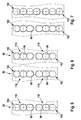
Figur 5, 6 und 7 ist dargestellt, wie Ständerwicklungen bzw. Reihen 90 von Runddrähten 93 bzw. Spulenseiten 96 in zwei Prägekammern 102 geprägt werden. Durch gleichmäßig hohe mechanische Füllung in den Kammern können optimierte elektromagnetische Auslegungen mit elektrischen Füllfaktoren größer 60% umgesetzt werden. Insbesondere Ständernutauslegungen mit trapezförmigen Nutformen profitieren von diesem Prinzip. - Durch Einsatz von zwei Prägekammern 102 kann eine gleichmäßige mechanische Füllung der Prägenuten erreicht werden. Dies ermöglicht unter Berücksichtigung der möglichen Drahttoleranzen einen Füllgrad der Prägenut nahe 100%. Optimierte elektromagnetische Auslegungen mit elektrischen Füllgraden größer 60% werden so möglich (siehe
Figur 5 ). - Es ist ein Verfahren vorgesehen, wobei die Spulenseiten 96 in mehreren Teilreihen 110 angeordnet sind, wobei mehrere Teilreihen 110 eine Nutreihe 90 bilden.
- Es ist gemäß
Figur 6 und 7 ein Verfahren vorgesehen, wobei die Spulenseiten 96 in mehreren Teilreihen 110 angeordnet sind, wobei mehrere Teilreihen 110 eine Nutreihe 90 bilden und pro Nut 99 mehrere Nutreihen 90 vorgesehen sind. Die Teilreihen 110 einer Nutreihe 90 weisen eine unterschiedliche Zahl an Spulenseiten 96 auf. - Die Teilreihen 110 werden in voneinander getrennten Prägekammern 102 geprägt.
- Rechnerische Prägenut-Füllungen größer 100% in Teilbereichen der Nut werden mit zwei Prägekammern vermieden. Unzulässige Verformungen an einzelnen Drähten treten nicht mehr auf, es wird kein Kupfer in Längsrichtung (senkrecht zur Darstellungsebene) in die elektromagnetisch nicht aktiven Wickelköpfe verschoben. D.h. die berechnete optimierte Auslegung kommt auch in Wirklichkeit zur Anwendung.
- Insbesondere können mit zwei getrennten Prägekammern auch Auslegungen mit trapezförmigen Nuten umgesetzt werden. Ausgleichsbewegungen zwischen dem schmalen und breiten Bereich der Prägekammer sind nicht notwendig. Schwer beherrschbare Einflüsse wie z.B. die Reibung innerhalb der Prägekammer haben keinen Einfluss auf die Ausführungsqualität. Eine Beschränkung bezüglich der Nutform liegt hierbei nicht vor, insbesondere sind unterschiedliche Trapezformen machbar.
- Das vorgeschlagene Prinzip lässt sich für verschiedene Auslegungen anwenden. Es können sowohl einreihige Drahtanordnungen wie z.B. bei einem 5-Phasen-System mit 80 Nuten (siehe
Figur 5 ), wie auch doppelreihige Anordnungen wie z.B. bei einem 3-Phasen-System mit 48 Nuten (sieheFigur 6 ) realisiert werden. Weitere mehrreihige Anordnungen sind prinzipiell denkbar, die Nutzahl bzw. die Polzahl der Auslegung sind dabei beliebig. Darüber hinaus können bei entsprechender Berechnung der Prägekammerflächen auch Auslegungen mit ungerader Leiterzahl gebaut werden (sieheFigur 7 ). - Das Prägen in zwei Kammern erzeugt eine eindeutige und vor allem reproduzierbare Trennebene zwischen Nutober- bzw. -unterlage. Unterschiedliche Bedingungen innerhalb der Prägenut, wie z.B. Reibung, Drahtfestigkeit oder Drahtdurchmesser haben keinen Einfluss auf diese Trennebene. Dies kann bei nachfolgenden Prozessschritten von großem Vorteil sein: Z. B. kann ein Schränkvorgang der Spulenelemente entlang dieser Trennebene erfolgen.
- Es ist ein Stator mit einer Ständerwicklung (18) vorgesehen, welche nach einem der hier vorgestellten Verfahrensschritte gefertigt ist.
Claims (7)
- Verfahren zum Prägen von mehreren Spulenseiten (96) für eine Ständerwicklung (18), dadurch gekennzeichnet, dass die mehreren Spulenseiten (96) in einer Nutreihe (90) angeordnet werden, wobei mit einer Kraft (F) umgeformt wird, deren Kraftrichtung einen Winkel (α) zu der Nutreihe (90) aufweist, der größer Null ist, so dass alle Spulenseiten im Nutbereich möglichst gleichmäßig verformt werden.
- Verfahren nach Anspruch 1, dadurch gekennzeichnet, dass die Spulenseiten (96) in mehreren Teilreihen (110) angeordnet sind, wobei mehrere Teilreihen (110) eine Nutreihe (90) bilden.
- Verfahren nach Anspruch 2, dadurch gekennzeichnet, dass die Spulenseiten (96) in mehreren Teilreihen (110) angeordnet sind, wobei mehrere Teilreihen (110) eine Nutreihe (90) bilden und pro Nut (99) mehrere Nutreihen (90) vorgesehen sind.
- Verfahren nach Anspruch 2 oder 3, dadurch gekennzeichnet, dass die Teilreihen (110) einer Nutreihe (90) eine unterschiedliche Zahl an Spulenseiten (96) aufweisen.
- Verfahren nach einem der vorstehenden Ansprüche, dadurch gekennzeichnet, dass Teilreihen (110) in voneinander getrennten Prägekammern (102) geprägt werden.
- Stator mit einer Ständerwicklung (18), welche nach einem der Ansprüche 1 bis 4 gefertigt ist.
- Elektrische Maschine (10) mit einem Stator (16) nach Anspruch 6.
Applications Claiming Priority (2)
| Application Number | Priority Date | Filing Date | Title |
|---|---|---|---|
| DE102010053716A DE102010053716A1 (de) | 2010-12-01 | 2010-12-01 | Verfahren zum Prägen von Spulenseiten einer Ständerwicklung |
| PCT/EP2011/071417 WO2012072695A2 (de) | 2010-12-01 | 2011-11-30 | Verfahren zum prägen von spulenseiten einer ständerwicklung |
Publications (2)
| Publication Number | Publication Date |
|---|---|
| EP2647108A2 EP2647108A2 (de) | 2013-10-09 |
| EP2647108B1 true EP2647108B1 (de) | 2014-11-05 |
Family
ID=45063143
Family Applications (1)
| Application Number | Title | Priority Date | Filing Date |
|---|---|---|---|
| EP11788846.1A Active EP2647108B1 (de) | 2010-12-01 | 2011-11-30 | Verfahren zum prägen von spulenseiten einer ständerwicklung |
Country Status (8)
| Country | Link |
|---|---|
| US (1) | US9780631B2 (de) |
| EP (1) | EP2647108B1 (de) |
| CN (1) | CN103250334B (de) |
| BR (1) | BR112013013547B1 (de) |
| DE (1) | DE102010053716A1 (de) |
| ES (1) | ES2525169T3 (de) |
| MX (1) | MX2013006013A (de) |
| WO (1) | WO2012072695A2 (de) |
Families Citing this family (5)
| Publication number | Priority date | Publication date | Assignee | Title |
|---|---|---|---|---|
| DE102013225667A1 (de) * | 2012-12-20 | 2014-06-26 | Robert Bosch Gmbh | Verfahren zum Verbinden von Anschlussdrähten einer Phasenwicklung einer Ständerwicklung für eine elektrische Maschine sowie elektrische Maschine |
| DE102017209792B4 (de) | 2017-06-09 | 2023-10-05 | Fraunhofer-Gesellschaft zur Förderung der angewandten Forschung e.V. | Halbzeug für eine elektrotechnische Spule sowie Verfahren und Vorrichtung zur Herstellung desselben |
| DE102017213106B4 (de) | 2017-07-31 | 2024-05-29 | Fraunhofer-Gesellschaft zur Förderung der angewandten Forschung e.V. | Verfahren zur Herstellung einer elektrotechnischen Spule |
| DE102017213151A1 (de) | 2017-07-31 | 2019-01-31 | Fraunhofer-Gesellschaft zur Förderung der angewandten Forschung e.V. | Elektrotechnische Spule sowie Verfahren und Halbzeug zur Herstellung derselben |
| US11478840B2 (en) * | 2017-09-28 | 2022-10-25 | Nidec Corporation | Manufacturing method of wire rod, manufacturing apparatus of wire rod, wire rod, and motor |
Family Cites Families (10)
| Publication number | Priority date | Publication date | Assignee | Title |
|---|---|---|---|---|
| US4177397A (en) * | 1978-03-17 | 1979-12-04 | Amp Incorporated | Electrical connections for windings of motor stators |
| US4147398A (en) * | 1978-03-17 | 1979-04-03 | Amp Incorporated | Selective electrical connections among wires of different diameters |
| JP3550880B2 (ja) * | 1996-05-31 | 2004-08-04 | 株式会社日立製作所 | モータ及びモータの固定子コイル端末線接続方法 |
| US6229241B1 (en) * | 1997-03-26 | 2001-05-08 | Hitachi, Ltd. | Structure and manufacturing method for motor and stator |
| JP3578142B2 (ja) * | 2002-01-15 | 2004-10-20 | 株式会社日立製作所 | 接続構造とその接続方法及びそれを用いた回転電機並びに交流発電機 |
| DE10190175D2 (de) | 2000-01-20 | 2002-05-29 | Bosch Gmbh Robert | Verfahren zur Herstellung eines magnetisch erregbaren Kerns mit Kernwicklung für eine elektrische Maschine |
| US7132775B2 (en) * | 2002-12-26 | 2006-11-07 | Mitsubishi Denki Kabushiki Kaisha | Stator of dynamoelectric machine and method for manufacturing stator winding |
| DE102005048094A1 (de) * | 2005-09-30 | 2007-04-05 | Robert Bosch Gmbh | Verfahren und Vorrichtung zur Herstellung einer Wicklung für elektrische Maschinen |
| DE102007034322A1 (de) * | 2007-07-24 | 2009-01-29 | Robert Bosch Gmbh | Verfahren zur Herstellung einer vorzugsweise mehrphasigen Wicklung für den Stator einer elektrischen Maschine |
| CN101320623A (zh) * | 2008-03-21 | 2008-12-10 | 歌尔声学股份有限公司 | 一种制造非圆形横截面形状线圈的方法 |
-
2010
- 2010-12-01 DE DE102010053716A patent/DE102010053716A1/de not_active Withdrawn
-
2011
- 2011-11-30 ES ES11788846.1T patent/ES2525169T3/es active Active
- 2011-11-30 CN CN201180058161.0A patent/CN103250334B/zh active Active
- 2011-11-30 US US13/991,332 patent/US9780631B2/en active Active
- 2011-11-30 EP EP11788846.1A patent/EP2647108B1/de active Active
- 2011-11-30 WO PCT/EP2011/071417 patent/WO2012072695A2/de not_active Ceased
- 2011-11-30 BR BR112013013547A patent/BR112013013547B1/pt not_active IP Right Cessation
- 2011-11-30 MX MX2013006013A patent/MX2013006013A/es active IP Right Grant
Also Published As
| Publication number | Publication date |
|---|---|
| WO2012072695A2 (de) | 2012-06-07 |
| US20130257215A1 (en) | 2013-10-03 |
| WO2012072695A3 (de) | 2013-01-10 |
| BR112013013547B1 (pt) | 2020-04-07 |
| CN103250334A (zh) | 2013-08-14 |
| BR112013013547A2 (pt) | 2016-10-11 |
| US9780631B2 (en) | 2017-10-03 |
| BR112013013547A8 (pt) | 2018-08-14 |
| CN103250334B (zh) | 2017-02-15 |
| DE102010053716A1 (de) | 2012-06-06 |
| ES2525169T3 (es) | 2014-12-18 |
| EP2647108A2 (de) | 2013-10-09 |
| MX2013006013A (es) | 2013-07-15 |
Similar Documents
| Publication | Publication Date | Title |
|---|---|---|
| DE102005004133A1 (de) | Elektromotor | |
| DE102009024230A1 (de) | Verfahren zur Herstellung einer Ständerwicklung einer elektrischen Maschine, insbesondere zur Herstellung eines Wechselstromgenerators | |
| DE102007034322A1 (de) | Verfahren zur Herstellung einer vorzugsweise mehrphasigen Wicklung für den Stator einer elektrischen Maschine | |
| DE102012100332A1 (de) | Stator für eine rotierende elektrische Maschine und Verfahren zu seiner Herstellung | |
| WO2012072695A2 (de) | Verfahren zum prägen von spulenseiten einer ständerwicklung | |
| EP1883149B1 (de) | Radiale Zentrierfläche eines Ständerkerns | |
| EP2936662B1 (de) | Elektrische maschine | |
| DE102018111119A1 (de) | Verfahren zum Herstellen einer Wicklung für einen Ständer einer elektrischen Maschine und elektrische Maschine | |
| DE102010053719A1 (de) | Verfahren zur Herstellung einer Ständerwicklung einer elektrischen Maschine, insbesondere zur Herstellung eines Wechselstromgenerators | |
| EP3934067A1 (de) | Wicklungssystem für eine elektrische maschine | |
| EP3317947A1 (de) | Permanent erregte elektrische maschine mit optimierter geometrie | |
| WO2006122985A1 (de) | Fünfphasiger generator | |
| EP1969697B1 (de) | Elektrische Maschine, insbesondere Wechselstromgenerator für ein Kraftfahrzeug | |
| EP1702397B1 (de) | Klauenpolläufer für eine elektrische maschine | |
| DE102019124183A1 (de) | Stator für einen Elektromotor | |
| DE102020109482B4 (de) | Verfahren zum Herstellen eines Stators für eine elektrische Maschine, entsprechender Stator sowie Verfahren zum Betreiben einer elektrischen Maschine, entsprechender Stator sowie Verfahren zum Betreiben einer elektrischen Maschine | |
| EP1850463B1 (de) | Verfahren und Vorrichtung zur Herstellung von Schweißverbindungen an Leitern einer elektrischen Maschine | |
| DE102020207913A1 (de) | Stator einer elektrischen Maschine aufweisend eine Wickelkopfkühlung | |
| WO2017012765A1 (de) | Permanent erregte elektrische maschine mit optimierter geometrie | |
| EP2647104B1 (de) | Ständerwicklung mit mehreren phasenwicklungen | |
| DE102008054389A1 (de) | Elektrische Maschine mit einem Klauenpolrotor | |
| DE102014213578A1 (de) | Statorelement, Stator, elektrische Maschine sowie Verfahren zum Herstellen eines Statorelements für eine elektrische Maschine | |
| EP2304865A1 (de) | Elektrische maschine | |
| DE102014218542A1 (de) | Geblechter Stator für Axialmagnetlager | |
| DE102016208150A1 (de) | Stator einer elektrischen Maschine mit einer Verschaltungseinrichtung für Statorspulen und elektrische Maschine mit einem derartigen Stator |
Legal Events
| Date | Code | Title | Description |
|---|---|---|---|
| PUAI | Public reference made under article 153(3) epc to a published international application that has entered the european phase |
Free format text: ORIGINAL CODE: 0009012 |
|
| 17P | Request for examination filed |
Effective date: 20130710 |
|
| AK | Designated contracting states |
Kind code of ref document: A2 Designated state(s): AL AT BE BG CH CY CZ DE DK EE ES FI FR GB GR HR HU IE IS IT LI LT LU LV MC MK MT NL NO PL PT RO RS SE SI SK SM TR |
|
| DAX | Request for extension of the european patent (deleted) | ||
| GRAP | Despatch of communication of intention to grant a patent |
Free format text: ORIGINAL CODE: EPIDOSNIGR1 |
|
| RIC1 | Information provided on ipc code assigned before grant |
Ipc: H02K 15/04 20060101AFI20140701BHEP Ipc: H02K 3/12 20060101ALN20140701BHEP |
|
| INTG | Intention to grant announced |
Effective date: 20140730 |
|
| RIC1 | Information provided on ipc code assigned before grant |
Ipc: H02K 15/04 20060101AFI20140722BHEP Ipc: H02K 3/12 20060101ALN20140722BHEP |
|
| GRAS | Grant fee paid |
Free format text: ORIGINAL CODE: EPIDOSNIGR3 |
|
| GRAA | (expected) grant |
Free format text: ORIGINAL CODE: 0009210 |
|
| AK | Designated contracting states |
Kind code of ref document: B1 Designated state(s): AL AT BE BG CH CY CZ DE DK EE ES FI FR GB GR HR HU IE IS IT LI LT LU LV MC MK MT NL NO PL PT RO RS SE SI SK SM TR |
|
| REG | Reference to a national code |
Ref country code: GB Ref legal event code: FG4D Free format text: NOT ENGLISH |
|
| REG | Reference to a national code |
Ref country code: CH Ref legal event code: EP |
|
| REG | Reference to a national code |
Ref country code: AT Ref legal event code: REF Ref document number: 695043 Country of ref document: AT Kind code of ref document: T Effective date: 20141115 |
|
| REG | Reference to a national code |
Ref country code: IE Ref legal event code: FG4D Free format text: LANGUAGE OF EP DOCUMENT: GERMAN |
|
| REG | Reference to a national code |
Ref country code: DE Ref legal event code: R096 Ref document number: 502011004912 Country of ref document: DE Effective date: 20141218 Ref country code: ES Ref legal event code: FG2A Ref document number: 2525169 Country of ref document: ES Kind code of ref document: T3 Effective date: 20141218 |
|
| REG | Reference to a national code |
Ref country code: NL Ref legal event code: VDEP Effective date: 20141105 |
|
| REG | Reference to a national code |
Ref country code: LT Ref legal event code: MG4D |
|
| PG25 | Lapsed in a contracting state [announced via postgrant information from national office to epo] |
Ref country code: LT Free format text: LAPSE BECAUSE OF FAILURE TO SUBMIT A TRANSLATION OF THE DESCRIPTION OR TO PAY THE FEE WITHIN THE PRESCRIBED TIME-LIMIT Effective date: 20141105 Ref country code: NO Free format text: LAPSE BECAUSE OF FAILURE TO SUBMIT A TRANSLATION OF THE DESCRIPTION OR TO PAY THE FEE WITHIN THE PRESCRIBED TIME-LIMIT Effective date: 20150205 Ref country code: FI Free format text: LAPSE BECAUSE OF FAILURE TO SUBMIT A TRANSLATION OF THE DESCRIPTION OR TO PAY THE FEE WITHIN THE PRESCRIBED TIME-LIMIT Effective date: 20141105 Ref country code: NL Free format text: LAPSE BECAUSE OF FAILURE TO SUBMIT A TRANSLATION OF THE DESCRIPTION OR TO PAY THE FEE WITHIN THE PRESCRIBED TIME-LIMIT Effective date: 20141105 Ref country code: PT Free format text: LAPSE BECAUSE OF FAILURE TO SUBMIT A TRANSLATION OF THE DESCRIPTION OR TO PAY THE FEE WITHIN THE PRESCRIBED TIME-LIMIT Effective date: 20150305 Ref country code: IS Free format text: LAPSE BECAUSE OF FAILURE TO SUBMIT A TRANSLATION OF THE DESCRIPTION OR TO PAY THE FEE WITHIN THE PRESCRIBED TIME-LIMIT Effective date: 20150305 |
|
| PG25 | Lapsed in a contracting state [announced via postgrant information from national office to epo] |
Ref country code: CY Free format text: LAPSE BECAUSE OF FAILURE TO SUBMIT A TRANSLATION OF THE DESCRIPTION OR TO PAY THE FEE WITHIN THE PRESCRIBED TIME-LIMIT Effective date: 20141105 Ref country code: PL Free format text: LAPSE BECAUSE OF FAILURE TO SUBMIT A TRANSLATION OF THE DESCRIPTION OR TO PAY THE FEE WITHIN THE PRESCRIBED TIME-LIMIT Effective date: 20141105 Ref country code: GR Free format text: LAPSE BECAUSE OF FAILURE TO SUBMIT A TRANSLATION OF THE DESCRIPTION OR TO PAY THE FEE WITHIN THE PRESCRIBED TIME-LIMIT Effective date: 20150206 Ref country code: SE Free format text: LAPSE BECAUSE OF FAILURE TO SUBMIT A TRANSLATION OF THE DESCRIPTION OR TO PAY THE FEE WITHIN THE PRESCRIBED TIME-LIMIT Effective date: 20141105 Ref country code: HR Free format text: LAPSE BECAUSE OF FAILURE TO SUBMIT A TRANSLATION OF THE DESCRIPTION OR TO PAY THE FEE WITHIN THE PRESCRIBED TIME-LIMIT Effective date: 20141105 Ref country code: RS Free format text: LAPSE BECAUSE OF FAILURE TO SUBMIT A TRANSLATION OF THE DESCRIPTION OR TO PAY THE FEE WITHIN THE PRESCRIBED TIME-LIMIT Effective date: 20141105 Ref country code: LV Free format text: LAPSE BECAUSE OF FAILURE TO SUBMIT A TRANSLATION OF THE DESCRIPTION OR TO PAY THE FEE WITHIN THE PRESCRIBED TIME-LIMIT Effective date: 20141105 |
|
| PG25 | Lapsed in a contracting state [announced via postgrant information from national office to epo] |
Ref country code: BE Free format text: LAPSE BECAUSE OF NON-PAYMENT OF DUE FEES Effective date: 20141130 |
|
| REG | Reference to a national code |
Ref country code: CH Ref legal event code: PL |
|
| PG25 | Lapsed in a contracting state [announced via postgrant information from national office to epo] |
Ref country code: DK Free format text: LAPSE BECAUSE OF FAILURE TO SUBMIT A TRANSLATION OF THE DESCRIPTION OR TO PAY THE FEE WITHIN THE PRESCRIBED TIME-LIMIT Effective date: 20141105 Ref country code: LI Free format text: LAPSE BECAUSE OF NON-PAYMENT OF DUE FEES Effective date: 20141130 Ref country code: CZ Free format text: LAPSE BECAUSE OF FAILURE TO SUBMIT A TRANSLATION OF THE DESCRIPTION OR TO PAY THE FEE WITHIN THE PRESCRIBED TIME-LIMIT Effective date: 20141105 Ref country code: EE Free format text: LAPSE BECAUSE OF FAILURE TO SUBMIT A TRANSLATION OF THE DESCRIPTION OR TO PAY THE FEE WITHIN THE PRESCRIBED TIME-LIMIT Effective date: 20141105 Ref country code: SK Free format text: LAPSE BECAUSE OF FAILURE TO SUBMIT A TRANSLATION OF THE DESCRIPTION OR TO PAY THE FEE WITHIN THE PRESCRIBED TIME-LIMIT Effective date: 20141105 Ref country code: CH Free format text: LAPSE BECAUSE OF NON-PAYMENT OF DUE FEES Effective date: 20141130 |
|
| REG | Reference to a national code |
Ref country code: DE Ref legal event code: R097 Ref document number: 502011004912 Country of ref document: DE |
|
| REG | Reference to a national code |
Ref country code: IE Ref legal event code: MM4A |
|
| PG25 | Lapsed in a contracting state [announced via postgrant information from national office to epo] |
Ref country code: MC Free format text: LAPSE BECAUSE OF FAILURE TO SUBMIT A TRANSLATION OF THE DESCRIPTION OR TO PAY THE FEE WITHIN THE PRESCRIBED TIME-LIMIT Effective date: 20141105 |
|
| PLBE | No opposition filed within time limit |
Free format text: ORIGINAL CODE: 0009261 |
|
| STAA | Information on the status of an ep patent application or granted ep patent |
Free format text: STATUS: NO OPPOSITION FILED WITHIN TIME LIMIT |
|
| 26N | No opposition filed |
Effective date: 20150806 |
|
| PG25 | Lapsed in a contracting state [announced via postgrant information from national office to epo] |
Ref country code: IE Free format text: LAPSE BECAUSE OF NON-PAYMENT OF DUE FEES Effective date: 20141130 |
|
| REG | Reference to a national code |
Ref country code: FR Ref legal event code: PLFP Year of fee payment: 5 |
|
| REG | Reference to a national code |
Ref country code: HU Ref legal event code: AG4A Ref document number: E024187 Country of ref document: HU |
|
| PG25 | Lapsed in a contracting state [announced via postgrant information from national office to epo] |
Ref country code: IT Free format text: LAPSE BECAUSE OF FAILURE TO SUBMIT A TRANSLATION OF THE DESCRIPTION OR TO PAY THE FEE WITHIN THE PRESCRIBED TIME-LIMIT Effective date: 20141105 |
|
| PG25 | Lapsed in a contracting state [announced via postgrant information from national office to epo] |
Ref country code: SI Free format text: LAPSE BECAUSE OF FAILURE TO SUBMIT A TRANSLATION OF THE DESCRIPTION OR TO PAY THE FEE WITHIN THE PRESCRIBED TIME-LIMIT Effective date: 20141105 |
|
| PG25 | Lapsed in a contracting state [announced via postgrant information from national office to epo] |
Ref country code: SM Free format text: LAPSE BECAUSE OF FAILURE TO SUBMIT A TRANSLATION OF THE DESCRIPTION OR TO PAY THE FEE WITHIN THE PRESCRIBED TIME-LIMIT Effective date: 20141105 |
|
| PG25 | Lapsed in a contracting state [announced via postgrant information from national office to epo] |
Ref country code: RO Free format text: LAPSE BECAUSE OF FAILURE TO SUBMIT A TRANSLATION OF THE DESCRIPTION OR TO PAY THE FEE WITHIN THE PRESCRIBED TIME-LIMIT Effective date: 20141105 |
|
| PG25 | Lapsed in a contracting state [announced via postgrant information from national office to epo] |
Ref country code: BG Free format text: LAPSE BECAUSE OF FAILURE TO SUBMIT A TRANSLATION OF THE DESCRIPTION OR TO PAY THE FEE WITHIN THE PRESCRIBED TIME-LIMIT Effective date: 20141105 |
|
| GBPC | Gb: european patent ceased through non-payment of renewal fee |
Effective date: 20151130 |
|
| PG25 | Lapsed in a contracting state [announced via postgrant information from national office to epo] |
Ref country code: LU Free format text: LAPSE BECAUSE OF NON-PAYMENT OF DUE FEES Effective date: 20141130 Ref country code: MT Free format text: LAPSE BECAUSE OF FAILURE TO SUBMIT A TRANSLATION OF THE DESCRIPTION OR TO PAY THE FEE WITHIN THE PRESCRIBED TIME-LIMIT Effective date: 20141105 Ref country code: TR Free format text: LAPSE BECAUSE OF FAILURE TO SUBMIT A TRANSLATION OF THE DESCRIPTION OR TO PAY THE FEE WITHIN THE PRESCRIBED TIME-LIMIT Effective date: 20141105 |
|
| PG25 | Lapsed in a contracting state [announced via postgrant information from national office to epo] |
Ref country code: GB Free format text: LAPSE BECAUSE OF NON-PAYMENT OF DUE FEES Effective date: 20151130 |
|
| REG | Reference to a national code |
Ref country code: FR Ref legal event code: PLFP Year of fee payment: 6 |
|
| REG | Reference to a national code |
Ref country code: FR Ref legal event code: PLFP Year of fee payment: 7 |
|
| REG | Reference to a national code |
Ref country code: DE Ref legal event code: R081 Ref document number: 502011004912 Country of ref document: DE Owner name: SEG AUTOMOTIVE GERMANY GMBH, DE Free format text: FORMER OWNER: ROBERT BOSCH GMBH, 70469 STUTTGART, DE |
|
| REG | Reference to a national code |
Ref country code: AT Ref legal event code: MM01 Ref document number: 695043 Country of ref document: AT Kind code of ref document: T Effective date: 20161130 |
|
| REG | Reference to a national code |
Ref country code: ES Ref legal event code: PC2A Owner name: SEG AUTOMOTIVE GERMANY GMBH Effective date: 20180119 |
|
| REG | Reference to a national code |
Ref country code: HU Ref legal event code: FH1C Free format text: FORMER REPRESENTATIVE(S): DR. JAKABNE MOLNAR JUDIT, SBGK SZABADALMI UEGYVIVOEI IRODA, HU Representative=s name: SBGK SZABADALMI UEGYVIVOEI IRODA, HU Ref country code: HU Ref legal event code: GB9C Owner name: SEG AUTOMOTIVE GERMANY GMBH, DE Free format text: FORMER OWNER(S): ROBERT BOSCH GMBH, DE |
|
| PG25 | Lapsed in a contracting state [announced via postgrant information from national office to epo] |
Ref country code: AT Free format text: LAPSE BECAUSE OF NON-PAYMENT OF DUE FEES Effective date: 20161130 |
|
| REG | Reference to a national code |
Ref country code: FR Ref legal event code: TP Owner name: SEG AUTOMOTIVE GERMANY GMBH, DE Effective date: 20180315 |
|
| PG25 | Lapsed in a contracting state [announced via postgrant information from national office to epo] |
Ref country code: MK Free format text: LAPSE BECAUSE OF FAILURE TO SUBMIT A TRANSLATION OF THE DESCRIPTION OR TO PAY THE FEE WITHIN THE PRESCRIBED TIME-LIMIT Effective date: 20141105 |
|
| PG25 | Lapsed in a contracting state [announced via postgrant information from national office to epo] |
Ref country code: AL Free format text: LAPSE BECAUSE OF FAILURE TO SUBMIT A TRANSLATION OF THE DESCRIPTION OR TO PAY THE FEE WITHIN THE PRESCRIBED TIME-LIMIT Effective date: 20141105 |
|
| REG | Reference to a national code |
Ref country code: DE Ref legal event code: R082 Ref document number: 502011004912 Country of ref document: DE Representative=s name: DEHNSGERMANY PARTNERSCHAFT VON PATENTANWAELTEN, DE Ref country code: DE Ref legal event code: R082 Ref document number: 502011004912 Country of ref document: DE Representative=s name: DEHNS GERMANY PARTNERSCHAFT MBB, DE |
|
| PGFP | Annual fee paid to national office [announced via postgrant information from national office to epo] |
Ref country code: FR Payment date: 20221117 Year of fee payment: 12 Ref country code: ES Payment date: 20221209 Year of fee payment: 12 |
|
| PGFP | Annual fee paid to national office [announced via postgrant information from national office to epo] |
Ref country code: HU Payment date: 20221130 Year of fee payment: 12 |
|
| PG25 | Lapsed in a contracting state [announced via postgrant information from national office to epo] |
Ref country code: HU Free format text: LAPSE BECAUSE OF NON-PAYMENT OF DUE FEES Effective date: 20231201 |
|
| PG25 | Lapsed in a contracting state [announced via postgrant information from national office to epo] |
Ref country code: FR Free format text: LAPSE BECAUSE OF NON-PAYMENT OF DUE FEES Effective date: 20231130 |
|
| PG25 | Lapsed in a contracting state [announced via postgrant information from national office to epo] |
Ref country code: FR Free format text: LAPSE BECAUSE OF NON-PAYMENT OF DUE FEES Effective date: 20231130 |
|
| REG | Reference to a national code |
Ref country code: ES Ref legal event code: FD2A Effective date: 20250108 |
|
| PG25 | Lapsed in a contracting state [announced via postgrant information from national office to epo] |
Ref country code: ES Free format text: LAPSE BECAUSE OF NON-PAYMENT OF DUE FEES Effective date: 20231201 |
|
| PG25 | Lapsed in a contracting state [announced via postgrant information from national office to epo] |
Ref country code: ES Free format text: LAPSE BECAUSE OF NON-PAYMENT OF DUE FEES Effective date: 20231201 |
|
| PGFP | Annual fee paid to national office [announced via postgrant information from national office to epo] |
Ref country code: DE Payment date: 20251118 Year of fee payment: 15 |