EP2646623B1 - Système de superstructures et section présentant le système de superstructures - Google Patents
Système de superstructures et section présentant le système de superstructures Download PDFInfo
- Publication number
- EP2646623B1 EP2646623B1 EP11801873.8A EP11801873A EP2646623B1 EP 2646623 B1 EP2646623 B1 EP 2646623B1 EP 11801873 A EP11801873 A EP 11801873A EP 2646623 B1 EP2646623 B1 EP 2646623B1
- Authority
- EP
- European Patent Office
- Prior art keywords
- circulation
- superstructures
- energy
- circulation area
- envelope
- Prior art date
- Legal status (The legal status is an assumption and is not a legal conclusion. Google has not performed a legal analysis and makes no representation as to the accuracy of the status listed.)
- Active
Links
- 238000010276 construction Methods 0.000 claims description 61
- 238000009826 distribution Methods 0.000 claims description 14
- 239000000463 material Substances 0.000 claims description 14
- 239000004035 construction material Substances 0.000 claims description 3
- 230000004438 eyesight Effects 0.000 claims description 3
- 230000005540 biological transmission Effects 0.000 claims description 2
- 238000012876 topography Methods 0.000 claims description 2
- 230000004313 glare Effects 0.000 claims 2
- 238000013459 approach Methods 0.000 description 3
- 230000008901 benefit Effects 0.000 description 3
- 230000006870 function Effects 0.000 description 3
- 230000010354 integration Effects 0.000 description 3
- 238000009434 installation Methods 0.000 description 2
- 230000009467 reduction Effects 0.000 description 2
- 230000000007 visual effect Effects 0.000 description 2
- 208000019914 Mental Fatigue Diseases 0.000 description 1
- 208000003464 asthenopia Diseases 0.000 description 1
- 230000003247 decreasing effect Effects 0.000 description 1
- 230000001788 irregular Effects 0.000 description 1
- 230000016776 visual perception Effects 0.000 description 1
Images


Classifications
-
- E—FIXED CONSTRUCTIONS
- E01—CONSTRUCTION OF ROADS, RAILWAYS, OR BRIDGES
- E01C—CONSTRUCTION OF, OR SURFACES FOR, ROADS, SPORTS GROUNDS, OR THE LIKE; MACHINES OR AUXILIARY TOOLS FOR CONSTRUCTION OR REPAIR
- E01C1/00—Design or layout of roads, e.g. for noise abatement, for gas absorption
- E01C1/002—Design or lay-out of roads, e.g. street systems, cross-sections ; Design for noise abatement, e.g. sunken road
-
- H—ELECTRICITY
- H02—GENERATION; CONVERSION OR DISTRIBUTION OF ELECTRIC POWER
- H02S—GENERATION OF ELECTRIC POWER BY CONVERSION OF INFRARED RADIATION, VISIBLE LIGHT OR ULTRAVIOLET LIGHT, e.g. USING PHOTOVOLTAIC [PV] MODULES
- H02S20/00—Supporting structures for PV modules
-
- Y—GENERAL TAGGING OF NEW TECHNOLOGICAL DEVELOPMENTS; GENERAL TAGGING OF CROSS-SECTIONAL TECHNOLOGIES SPANNING OVER SEVERAL SECTIONS OF THE IPC; TECHNICAL SUBJECTS COVERED BY FORMER USPC CROSS-REFERENCE ART COLLECTIONS [XRACs] AND DIGESTS
- Y02—TECHNOLOGIES OR APPLICATIONS FOR MITIGATION OR ADAPTATION AGAINST CLIMATE CHANGE
- Y02E—REDUCTION OF GREENHOUSE GAS [GHG] EMISSIONS, RELATED TO ENERGY GENERATION, TRANSMISSION OR DISTRIBUTION
- Y02E10/00—Energy generation through renewable energy sources
- Y02E10/50—Photovoltaic [PV] energy
Definitions
- the present invention relates to superstructures carrying renewable energy means and disposed along sections comprising or in the proximity of circulation areas.
- the present invention also relates to a section, such as of a traffic infrastructure, including a system of superstructures according to the invention.
- the WO2010/0064942 first addresses the issues above and discloses sections of traffic infrastructures including certain distributions of superstructures and respective energy and information means in view of said comfort and security issues. This is achieved by distributions of successive superstructures of certain, eventually varying, lengths and distances in-between, preferentially predefined at least in view of local reference traffic conditions.
- this approach does not provide a solution for the particular cases of having successive superstructures disposed either directly adjacent or spaced by regular distances apart, along traffic ways.
- such approach might often not represent a solution for meeting a relatively high linear density of local energy demand along such sections, as expressed in terms of both installed generation capacity (i.e., kW/ km).
- WO2010/055229 A1 relates to a covering installation for protecting against the sun, comprising at least one covering-forming element and a load-bearing structure supporting said covering-forming element, said structure comprising at least one module formed by an assembly of uprights and a framework on which said covering-forming element rests.
- This module additionally comprises pedestals which can be placed on the ground and which are designed, through their own weight alone, to provide said module with self-stability, this installation being noteworthy in that said module is designed to straddle a plurality of parking spaces without intermediate support.
- the covering- forming element can comprise a network of photovoltaic panels.
- the present invention primarily addresses the problem that the overall construction resulting from superstructures installed has important impacts upon the comfort and security of people, in particular drivers, circulating along circulation ways.
- impacts are both in terms of direct security aspects, such as reductions of surrounding vision field, and of indirect aspects such as induced visual and mental fatigue, for example resulting from monotonous repetition of substantially similar constructions and patterns along substantial extensions.
- impacts are also in terms of design integration of said superstructures into respective (natural or urban) surroundings - an aspect of increasing importance to the development of renewable energy.
- the goal of the present invention is to provide a system of at least one, preferentially several superstructures, at least presenting renewable energy means, of at least one type, preferentially also information means, installed successively along the longitudinal direction of a section comprising at least one circulation area, in particular a traffic infrastructure, such that, even in the case of superstructures of relatively big lengths and/ or of a relatively high density of superstructures, the resulting overall construction does not substantially constrain safety and comfort aspects, in particular of drivers circulating along such a section.
- a related goal of the present invention is to provide a system of superstructures for a section comprising a circulation area of any extension, such that despite of construction aspects such as relatively high construction density, substantially regular distribution of superstructures and/ or similar construction elements thereof, it is designed so that it also considers circulating comfort and security, as well as a flexible and least-intrusive integration of the resulting overall construction into local (natural or urban) surrounding landscape.
- all construction is to be understood as the set of visible elements in a system of superstructures arranged in a given spatial distribution, including along a given extension, having an impact upon the resulting overall visual perception, preferentially at least as perceived by people circulating along or being next to such a system of superstructures, and basically resulting from a respective structural construction and envelope construction.
- structural construction refers to the set of design parameters of construction elements of similar function such as structural elements of the superstructures and so-called energy envelopes defined by energy generation means, including their relative spatial position and orientation at least relative to a pavement level and/ or vertical projection of a proximal circulation area at each location along a respective longitudinal direction, and their formats, dimensions and materials, as well as any patterns resulting thereof.
- envelope construction refers to the set of design parameters of renewable energy means disposed in a respective energy envelope, including their relative spatial position and orientation at least in relation to a pavement level and/ or vertical projection of a proximal circulation area at each location along a respective longitudinal direction, and their formats, dimensions and materials, as well as any patterns resulting thereof.
- a system of superstructures comprising at least one, preferentially a plurality of superstructures presenting renewable energy means and installed along a longitudinal direction of a section, such that the overall construction of said superstructures varies preferentially at least along a longitudinal direction thereof, more preferentially at least as perceived by people moving along a circulation direction.
- the overall construction of said superstructures is designed to vary in substantially intentional or conscious relative disposition of structural elements and renewable energy means, including as reflection of certain local aspects, rather than in a substantially casual or random relative disposition, at least as perceived by people walking and/ or circulating in its proximity or along it.
- the variation of the general construction results from a variation of a reduced number of constructive parameters thereof, more preferentially a variation in a relative reduced proportion of such construction parameters, at least as perceived by people moving along a circulation direction, and in time.
- the system of superstructures according to the invention thus presents an overall construction at least corresponding to varying distributions of, and/ or at least different structural constructions or envelope constructions of said superstructures, at least along said longitudinal direction of a section.
- the structural construction of said superstructures may vary at least as a result of different relative positions or spatial orientations, at least of respective structural elements or of respective energy envelopes, at least in relation to a next structural element or energy envelope respectively, and/ or in relation to the circulation area of said section. Furthermore, the structural construction of said superstructures may also vary as a result at least of different formats, or dimensions, or construction materials, at least of respective structural elements or of respective energy envelopes.
- the envelope construction of said energy envelopes may vary at least as a result of different relative positions or spatial orientations of said renewable energy means, at least in relation to a respective energy envelope or to a neighbouring renewable energy means.
- the renewable energy means preferentially present one format and at least two respective sizes, or several formats, each presenting at least one, preferentially several respective sizes, preferentially defined in such a way that they may be disposed directly adjacent to each other thereby forming a substantially continuous envelope area.
- said renewable energy means are preferentially disposed individually, or in groups thereof, at a distance from neighbouring renewable energy means or groups thereof, within respective energy envelopes, at least as a function of local geographic orientation and dimensions of the circulation area.
- successive superstructures may be disposed in substantially regular distributions and present substantially similar structural construction, but present such differently arranged and/ or different renewable energy means that a respective envelope construction varies, preferentially at least along a circulation direction.
- the variation of the overall construction of said superstructures is preferentially defined so as to reflect at least the local variation of reference aspects along the longitudinal direction of said section, including type of surroundings, terrain topography, construction characteristics and dimensions of circulation area, visibility conditions, or at least of reference aspects of circulation flow, including traffic typology and distribution, recommended circulation speed, or at least other traffic related aspects including presence of traffic support facilities.
- each superstructure presents at least one set of structural elements disposed successively at a circulation level and/ or an elevated level, and at least the relative position, or the spatial orientation, at least in relation to a proximal circulation area or to a next superstructure, or at least the format, or dimensions, or materials of said structural elements are defined with advantage as a function of factors including the vision field resulting at the circulation level, and the local inclination and curvature of the circulation area, preferentially at least as perceived by people circulating there along.
- the overall construction of said superstructures follows a substantially continuous variation, preferentially at least as perceived by people circulating along said circulation area.
- the overall construction of successive superstructures preferentially forms a pattern, or a sequence of patterns, preferentially at least as perceived by people circulating along said circulation area, thereby preferentially conveying to said people at least the evolution of general circulation aspects along said circulation area.
- at least the structural construction or at least the envelope construction is different in each circulation direction and/ or varies in a different way in each circulation direction along said circulation area. This allows to better customize the overall construction to respective local variations.
- the present invention further discloses a section comprising at least one system of superstructures according to any of the aforementioned aspects, whereby said section corresponds to a given spatial extension comprising or in the proximity of a circulation area, in particular of a traffic infrastructure, or another area of public or private use.
- such section comprises at least one system disposed along at least one of the circulation directions. Moreover, it is preferred when a next section presents a different system from the one in a previous section. According to another aspect, when said section corresponds to a section of a traffic infrastructure, then it is preferred that said superstructures are disposed at least along the sideways and/ or the area dividing circulation directions, or at least partially above of the circulation area.
- system of superstructures according to the invention is also applicable to sections of other spaces, including other areas of public use, such as public parks, and other superstructures, including buildings.
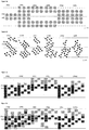
- Figures 1a to 1c represent individual superstructures (10a, %), in the particular case of being disposed at substantially similar distances apart, comprising structural elements (1a, 7) presenting energy envelopes (2a, 7) formed by a disposition of renewable energy means, such as for example solar energy means (5a, 7), in a section (A) in the proximity of a circulation area, such as for example a traffic infrastructure.
- renewable energy means such as for example solar energy means (5a, ...)
- Figures 1a to 1c are schematic examples of a system of said superstructures (10a, ...) according to the invention, whereby a variable overall construction along a circulation direction results primarily from a different relative position and/ or spatial orientation of the structural construction, in particular of the structural elements (1a, ...) of respective superstructures (10a, ...) in relation to a next superstructure (10b, ...) and/ or to a proximal circulation area.
- Figure 1a is a plane view of a first embodiment, whereby a plurality of superstructures (10a, ...) is disposed at a substantially regular distance apart and presents substantially similar energy envelopes (2a, ...), but different relative positions in relation to the circulation area, eventually leading to different structural constructions as further depicted by Figure 1b in respective front views for three different locations (A 1 , A 2 , A 3 ) along the circulation direction of section (A).
- structural elements (1a) in superstructure (10a) present a relative position in which they are disposed, for example, along both sideways and are spatially organized in such a way that it results in a substantially portico-like structural form.
- structural elements (1a) of superstructure (10c) are disposed, for example, along an East facing sideway and spatially organized so as to produce an "inverted L"-like structural form.
- the structural elements (1a) of superstructure (10f) are disposed, for example, along a dividing area of the circulation directions, and are spatially organized in a substantially "T-like" structural form.
- the structural construction could also be varied by means of varying the spatial orientation of structural elements (1a) directly associated with the, at least one, energy envelope (2a) of at least one superstructure (10a, ...), in relation to a next superstructure (10b, ...) and/ or to a proximal circulation area, as schematically indicated by the dashed lines in Figure 1b.
- Figure 1c illustrates another embodiment of a system according to the invention whereby the structural elements (1a, ...) of superstructures (10a, ...) are disposed in different relative spatial orientations relative to a next superstructure and/ or to a proximal circulation area of section (A) so that respective energy envelopes (2a, ...) present different orientations too.
- structural elements (1a, ...) and energy envelopes (2a, ...) may present a substantially similar form, dimensions or materials, i.e. a substantially similar construction design; overall construction of the system changes by varying at least the relative spatial position or the form of the structural construction of at least one, preferentially several superstructures (10a, ...), at least along a circulation direction of a section (A).
- Figures 2a to 2c represent a second set of embodiments of a system, in the particular case of a relative long superstructure (10a), whereby at least one of, preferentially several of, respective structural elements (1a, ...), besides of eventually varying their respective relative position and/ or spatial orientation, at least in relation to a proximal circulation area and/ or to a next structural element (1b, ...), also vary at least their respective form, dimensions, or materials, at least in relation to a next structural element (1b, ...), or superstructure (10b, 7), while thereby further presenting substantially similar energy envelopes (2a, ...) .
- Figure 2a represents a plan view of a special case of a system comprising one superstructure (10a) including several structural elements (1a, ...) disposed successively along a longitudinal direction, thereby varying respective relative spatial positions in relation to the circulation area, for example some along the sideways and others along the central dividing area.
- These structural elements (1a, ...) are disposed in a clustered arrangement, i.e. in substantial proximity of an adjacent one, but with different relative spatial positions in relation to the circulation area and thus leading to the overall construction of superstructure (10a) to vary at least along a respective traffic flow direction (x).
- energy envelopes (2a) may also extend beyond the vertical projection of the circulation area.
- Figure 2b depicts three side views of structural elements (1a, (7) at three successive locations of one superstructure (10a), whereby each thereby presents different form and dimensions (for example, the relative inclination of structural side elements - as illustrated).
- these structural elements (1a, ...) may present a different height along the circulation direction, so that respective solar energy means (5a, ...) are disposed at different heights (H 1 , H 2 , H 3 , respectively) relative to the pavement level (Ho) of a proximal circulation area.
- Figure 2c is a plan view of another system comprising one superstructure (10a), whereby all respective structural elements (1a, ...) are disposed in similar relative spatial positions, for example along the sideways of a proximal circulation area.
- structural elements (1a, ...) form a similar rectangular format containing at least one respective energy envelope (2a, 7), the difference being the relative location and number of said energy envelopes (2a, 7) in relation to said structural elements (1a, ).
- Substantially similar structural elements (1b, 1c, 1d) present, as illustrative example, an increasing number of substantially similar energy envelopes (2a, ...) resulting in a variation of the overall construction, preferentially at least as perceived by people circulating along the circulation area.
- Figures 3a to 3e illustrate a third set of embodiments of a system, whereby the structural construction of at least one, preferentially several superstructures (10a, 7) varies as a result of varying at least the spatial orientation of at least one respective structural element (1a, ...), or its form, or dimensions, or materials, at least relative to a next superstructure (10b, ...), or structural element (1b, 7), preferentially at least along a circulation direction (x).
- a circulation direction (x) it is further presented the case of disposing successive superstructures (10a, ...) at variable distances apart along a circulation direction (x).
- superstructures (10a) in these examples present only one energy envelope (2a) with at least one renewable energy (5a, ...) means, represented by the dashed areas, so that one abdicates from individually referencing these.
- Figures 3a to 3c are plane views of superstructures (10a, ...) presenting structural elements (1a, 7) at different spatial orientations relative to the circulation area, and eventually also relative a next structural element (1b, ...) and/ or superstructure (10b, ).
- successive structural elements (1a, 1b) are disposed in opposition across the circulation area and present different dimensions, including respective spans over the circulation area, thereby leading to best supporting a given trapezoidal format of a respective energy envelope (2a).
- structural elements (1a, 1b, 1c) are disposed in the same sideway at a similar distance apart, but in a variable spatial orientation in relation to the circulation area, again leading to a trapezoidal format of a respective energy envelope (2a).
- Figure 1c illustrates two successive superstructures (10a, 10b) basically made from one respective structural element (1a) with a similar format (in this case, arch-like) and different configurations thereof.
- these structural elements may then further vary in other superstructures (10b, ...) within a section (A), with advantage both in terms of better orientation of the energy envelope (2a, %) in view of renewable energy generation, and/ or in terms of conveying a given variation of reference circulation aspects to drivers.
- Figures 3d and 3e are plan views of two embodiments whereby a cluster of superstructures (10a, 7) is disposed so that they convey, for example, a decrease of recommended circulation speed along one (x 2 ) of the circulation directions ( Figure 3d ), and the presence of a curve ( Figure 3e ).
- energy envelopes (2a, ...) of each superstructure (10a, 7) might thereby have a substantially similar format and dimensions, but a different spatial orientation, including different inclination including relative to the pavement plane, and/ or a different relative position or distances apart, in relation to the circulation area, including as a result of different structural elements (1a, ...) and at least along a circulation direction (x) thereof.
- Figures 4a to 4f represent plan views of sections (A) comprising a fourth set of embodiments of a system, whereby the structural construction of respective superstructures (10a, 7) varies mostly as a result of varying at least the forms, or dimensions, or materials of energy envelopes (2a, 7), eventually also varying at least their respective relative position, or spatial orientation, at least in relation to the circulation area or to a neighbouring energy envelope (2b, 7), preferentially at least along a circulation direction (x).
- FIGs 4a and 4b there is represented the particular case of only one superstructure (10a) extending over most of the entire length of a section (A), whereby a respective energy envelope (2a) is suspended and/ or tensioned at least partially above of the circulation area, while thereby presenting one renewable energy means (5a), or one substantially continuous area of renewable energy means (5a, ).
- a respective energy envelope (2a) is suspended and/ or tensioned at least partially above of the circulation area, while thereby presenting one renewable energy means (5a), or one substantially continuous area of renewable energy means (5a, ).
- the format of the energy envelope (2a) is represented as that substantially occupied by respective, at least one, preferentially several, renewable energy means (5a, 6a, ).
- the format of this energy envelope (2a) is pre-defined such that it varies substantially at least along the traffic flow direction (x).
- the format of the energy envelope (2a) is pre-defined as substantially circular in the case of Figure 4a and triangular in the case of Figure 4b , and disposed so as to vary the resulting projection over the circulation area, at least as perceived by people circulating along a respective circulation direction (x) .
- Other formats are naturally feasible as such particular embodiments according to the present invention.
- Figures 4c and 4d represent energy envelopes of substantially similar format, but varying relative disposition, configuration and/ or dimensions.
- Figure 4c there are circular energy envelopes with an opening that is disposed in a variable relative position within a respective energy envelope (2a).
- Figure 4d there are energy envelopes (2a, 7) in different relative dispositions, including clusters thereof disposed in linear series and in transversal groups.
- Figures 4e and 4f also present energy envelopes (2a, 7) of substantially similar format, in this case triangular.
- Figure 4e there is a system of superstructures (10a, ...) presenting substantially similar structural elements (1a, 7) disposed at similar relative positions and spatial orientations, whereby respective energy envelopes (2a, 7) are arranged in different spatial orientations and provided in different dimensions.
- energy envelopes may extend over more than one superstructure and/ or beyond the vertical projection of a proximal circulation area, as for example in the case of that in the second and fourth superstructures (10b, 10d) .
- the form and dimension of energy envelopes (2a, ...) may be used to convey particular reference circulation aspects: for example the approximation of a curve by the energy envelope of the second superstructure (10b) in Figure 4e.
- Figure 4f illustrates the possibility of disposing energy envelopes (2a, %) in such a way that it results in several possibilities of different joint formats, at least as perceived by drivers circulating along a section (A) .
- the pattern resulting from the overall construction, including from respective construction envelopes of superstructures (10a, ...) may also be predefined so as to communicate or represent a given reference circulation aspect: for example, conveying an increasing recommended circulation speed along decreasing energy envelopes over the circulation area in Figure 4f .
- Figures 5a to 5d represent plan views of a fifth set of embodiments in which the overall construction of a system is varied by means of varying the envelope construction of at least one, preferentially several superstructures (10a, ...), at least along a circulation direction (x).
- this is achieved by varying the relative position and/ or spatial orientation of respective renewable energy means (5a, ...; 6a, ...), including in relation to a respective energy envelope (2a, %) and/ or to neighbouring renewable energy means (5b, ...; 6b, ...), and preferentially at least as perceived by people circulating along it.
- Figures 5c and 5d represent inventive examples of renewable energy means (5a, 7) of different materials (as illustrated by respectively lighter and darker patterns), having different light transmission properties, thus resulting in a variation of light and shadows being projected by each, including as perceived by people circulating along a circulation direction.
- a preferred alternative would be the use of materials associated with said renewable energy means (5a, %), for example as a wide area flexible element, disposed in their proximity on the side facing the circulation area, and presenting a given configuration pattern resulting in a variation at least of the light and shades being projected by said renewable energy means (5a, ...), at least as perceived by people circulating along a circulation direction (x 1 , x 2 ) .
- renewable energy means (5a, 7) of variable formats and/ or dimensions at least along a circulation direction (x) - somewhat similarly to the case of energy envelopes (2a, 7) depicted in Figure 4 .
Landscapes
- Engineering & Computer Science (AREA)
- Architecture (AREA)
- Civil Engineering (AREA)
- Structural Engineering (AREA)
- Road Paving Structures (AREA)
Claims (10)
- Système comportant une pluralité de superstructures (10a,...) installées dans une section (A) comportant au moins une zone de circulation, comprenant chacune des éléments structuraux (1a,...) portant une pluralité de moyens (5a,..., 6a,...) à énergie renouvelable définissant une enveloppe (2a,...) d'énergie respective, lesdites enveloppes (2a,...) d'énergie étant au moins sensiblement visibles depuis, ou à proximité de, ou faisant saillie au moins partiellement au-dessus d'une zone de circulation, et disposées à une distance régulière ou variable les unes des autres, de préférence à une distance réduite les unes des autres par rapport à leur longueur respective, idéalement directement adjacentes, suivant une direction (x1, x2) de circulation d'une zone proximale de circulation, ladite pluralité de superstructures (10a,...) étant ainsi installée successivement suivant la direction longitudinale (x) de ladite zone de circulation, et la construction d'ensemble desdites superstructures (10a,...) variant à l'intérieur de ladite section (A), au moins suivant ladite direction longitudinale (X) de celle-ci, chaque superstructure (10a,...) présentant ainsi une enveloppe (2a,...) d'énergie disposée dans un niveau surélevé (H1), et au moins la position relative ou l'orientation spatiale, au moins par rapport à une zone proximale de circulation ou à une enveloppe (2b,...) d'énergie voisine, étant définie en fonction de facteurs incluant les directions locales dominantes du soleil et/ou du vent, et les zones de lumière directe incidente sur le niveau (Ho) de circulation de la zone de circulation, notamment la taille respective, l'orientation relative, l'intensité lumineuse et l'éblouissement, caractérisé en ce que plusieurs superstructures (10a,...) diffèrent à l'intérieur de ladite section (A) par rapport à une quelconque autre superstructure (10a,...) à l'intérieur de ladite section (A), notamment en raison d'une variation au moins des matériaux de construction d'enveloppes (2a,...) d'énergie respectives comportant des moyens à énergie renouvelable de différents matériaux dotés de propriétés différentes de transmission lumineuse, entraînant une variation de la lumière et des ombres qui sont projetées par chacune, notamment telles que perçues par des personnes circulant suivant une direction de circulation.
- Système selon la revendication 1, caractérisé en ce que la construction structurale desdites superstructures (10a,...) varie au moins en raison de positions relatives ou d'orientations spatiales différentes, au moins d'éléments structuraux (1a,...) respectifs ou d'enveloppes (2a,...) d'énergie respectives, au moins par rapport à un élément structural (1b,...) ou une enveloppe (2b,...) d'énergie suivants respectivement et/ou par rapport à la zone de circulation de ladite section (A).
- Système selon l'une quelconque des revendications 1 ou 2 qui précèdent, caractérisé en ce que la construction d'enveloppes desdites enveloppes (2a,...) d'énergie varie au moins en raison de positions relatives ou d'orientations spatiales différentes desdits moyens (5a,... ; 6a,...) à énergie renouvelable, au moins par rapport à une enveloppe (2a) d'énergie respective ou à un moyen (5a,... ; 6a,...) à énergie renouvelable voisin.
- Système selon l'une quelconque des revendications 1 à 3 qui précèdent, caractérisé en ce que la construction d'enveloppes desdites enveloppes (2a,...) d'énergie varie en raison au moins de formats, ou de dimensions, ou de matériaux de construction différents, desdits moyens (5a,... ; 6a,...) à énergie renouvelable et/ou de matériaux associés à ceux-ci.
- Système selon l'une quelconque des revendications précédentes, caractérisé en ce que lesdits moyens (5a,... ; 6a,...) à énergie renouvelable présentent un format et au moins deux tailles respectives, ou plusieurs formats, présentant chacun au moins une, de préférence plusieurs tailles respectives, de préférence configurés de façon à pouvoir être disposés directement adjacents les uns aux autres, formant ainsi une enveloppe (2a) d'énergie sensiblement continue.
- Système selon l'une quelconque des revendications précédentes, caractérisé en ce que lesdits moyens (5a,... ; 6a,...) à énergie renouvelable sont disposés individuellement, ou par groupes, à une distance de moyens (5b,... ; 6b,...) à énergie renouvelable voisins ou de groupes de ceux-ci au sein d'enveloppes (2a,...) d'énergie respectives, au moins en fonction d'une orientation géographique locale et de dimensions de la zone de circulation.
- Système selon l'une quelconque des revendications précédentes, caractérisé en ce que la variation de la construction d'ensemble desdites superstructures (10a,...) est définie de manière à refléter au moins la variation locale d'aspects de référence suivant la direction longitudinale (x), notamment le type d'environs, la topographie du terrain, les caractéristiques de construction et les dimensions de la zone de circulation, les conditions de visibilité, ou au moins d'aspects de référence d'écoulement de trafic, notamment la typologie et la distribution du trafic, la vitesse de circulation recommandée, ou au moins d'autres aspects liés au trafic, notamment la présence d'installations d'assistance au trafic.
- Système selon l'une quelconque des revendications précédentes, caractérisé en ce que chaque superstructure (10a,...) présente au moins un ensemble d'éléments structuraux (1a,...) disposés successivement à un niveau (Ho) de circulation et/ou au niveau surélevé (H1), et au moins la position relative, ou l'orientation spatiale, au moins par rapport à une zone proximale de circulation ou à une superstructure (10b,...) suivante, ou au moins le format, ou les dimensions, desdits éléments structuraux (1a,...) étant définis en fonction de facteurs incluant le champ de vision résultant au niveau (Ho) de circulation, et l'inclinaison locale et la courbure de la zone de circulation.
- Système selon l'une quelconque des revendications précédentes, caractérisé en ce que chaque superstructure (10a,...) présente au moins un moyen (5a,... ; 6a,...) à énergie renouvelable disposé à l'intérieur d'une enveloppe (2a,...) d'énergie respective, et au moins la position relative ou l'orientation spatiale, au moins par rapport à une enveloppe (2a,...) d'énergie respective ou à un moyen (5b,... ; 6b,...) à énergie renouvelable voisin, ou au moins le format ou les dimensions desdits moyens à énergie renouvelable (5a, 6a,...) étant définis en fonction de facteurs incluant les zones de lumière incidente sur le niveau (Ho) de circulation notamment la taille respective, l'orientation relative, l'intensité lumineuse et l'éblouissement lumineux, et les zones d'ombre projetées sur le niveau (Ho) de circulation d'une zone de circulation, notamment la taille respective, la tonalité, l'étendue de motif, la fréquence de variation.
- Section (A) comportant au moins un système (1) de superstructures (10a,...) selon l'une quelconque des revendications 1 à 9, caractérisée en ce que ladite section (A) correspond à une étendue spatiale donnée comportant ou à proximité d'au moins une zone de circulation, en particulier d'une infrastructure de trafic, ou d'une autre zone, à usage public ou privé.
Applications Claiming Priority (2)
| Application Number | Priority Date | Filing Date | Title |
|---|---|---|---|
| PT10541410 | 2010-12-01 | ||
| PCT/PT2011/000041 WO2012074423A1 (fr) | 2010-12-01 | 2011-11-25 | Système de superstructures et section présentant un tel système de superstructures |
Publications (2)
| Publication Number | Publication Date |
|---|---|
| EP2646623A1 EP2646623A1 (fr) | 2013-10-09 |
| EP2646623B1 true EP2646623B1 (fr) | 2021-10-13 |
Family
ID=45406825
Family Applications (1)
| Application Number | Title | Priority Date | Filing Date |
|---|---|---|---|
| EP11801873.8A Active EP2646623B1 (fr) | 2010-12-01 | 2011-11-25 | Système de superstructures et section présentant le système de superstructures |
Country Status (3)
| Country | Link |
|---|---|
| US (1) | US9133585B2 (fr) |
| EP (1) | EP2646623B1 (fr) |
| WO (1) | WO2012074423A1 (fr) |
Families Citing this family (1)
| Publication number | Priority date | Publication date | Assignee | Title |
|---|---|---|---|---|
| US9570639B2 (en) | 2011-07-12 | 2017-02-14 | Paulo Alexandre Teixeira E. Silva Cardoso | System with gradual change of light distribution or shadow distribution on a surface comprising light elements or photovoltaic elements |
Family Cites Families (37)
| Publication number | Priority date | Publication date | Assignee | Title |
|---|---|---|---|---|
| US3979597A (en) * | 1974-03-05 | 1976-09-07 | Drucker Ernest R | Solar power plant |
| US4321476A (en) * | 1980-06-24 | 1982-03-23 | Buels Jesse H | Bi-directional wind power generator |
| DE3412584A1 (de) | 1984-04-04 | 1985-10-24 | Karlheinz Schulz | Sonnenkraftanlage |
| US5118361A (en) * | 1990-05-21 | 1992-06-02 | The Boeing Company | Terrestrial concentrator solar cell module |
| US5228924A (en) * | 1991-11-04 | 1993-07-20 | Mobil Solar Energy Corporation | Photovoltaic panel support assembly |
| DE4417065A1 (de) | 1993-06-27 | 1995-01-05 | Bernhard Miller | Fahrzeugführungssystem für Elektrofahrzeuge mit solarer Energieversorgung |
| EP0802324A1 (fr) | 1996-04-20 | 1997-10-22 | Rolf Höricht | Eolienne |
| US6563040B2 (en) * | 2001-10-11 | 2003-05-13 | Pinnacle West Capital Corporation | Structure for supporting a photovoltaic module in a solar energy collection system |
| ITTV20010055U1 (it) * | 2001-11-20 | 2003-05-20 | Gilberto Mattiuzzo | Struttura di dispositivo di trasformazione della radiazione solare inenergia elettrica |
| ATE402487T1 (de) * | 2003-03-10 | 2008-08-15 | Sunpower Corp Systems | Modular-schattensystem mit solarverfolgungstafeln |
| US8875450B2 (en) * | 2003-04-02 | 2014-11-04 | P4P Holdings, LLC | Solar array system for covering a body of water |
| US7190531B2 (en) * | 2003-06-03 | 2007-03-13 | Rensselaer Polytechnic Institute | Concentrating type solar collection and daylighting system within glazed building envelopes |
| US7193332B2 (en) * | 2004-10-25 | 2007-03-20 | Omnitek Partners Llc | Methods and apparatus for generating power from vehicles |
| US7067932B1 (en) * | 2005-01-07 | 2006-06-27 | Faramarz Frank Ghassemi | System for generating electricity by using gravitational mass and/or momentum of moving vehicle |
| US7098553B2 (en) * | 2005-01-12 | 2006-08-29 | Theodore F Wiegel | Traffic-driven wind generator |
| US20060210358A1 (en) * | 2005-03-17 | 2006-09-21 | Jui-Wen Chen | Constructive water resource recycling method |
| US7427173B2 (en) * | 2005-09-15 | 2008-09-23 | Taiming Chen | Power generation system utilizing wind draft from vehicular traffic |
| IL176619A0 (en) * | 2006-06-29 | 2006-10-31 | Zalman Schwartzman | A photovoltaic array for concentrated solar energy generator |
| US7566980B2 (en) * | 2006-12-22 | 2009-07-28 | Genedics Clean Energy, Llc | System and method for creating a geothermal roadway utility with alternative energy pumping system |
| US7501713B2 (en) * | 2006-12-22 | 2009-03-10 | Genedics Llc | System and method for creating a networked infrastructure roadway distribution platform of solar energy gathering devices |
| US7909567B2 (en) * | 2006-12-22 | 2011-03-22 | Genedics Clean Energy, Llc | Stratum deployment of wind turbines |
| DE102007021438A1 (de) | 2007-05-08 | 2008-11-13 | Adam Korsitzky | Energieanlage zur Nutzung regenerativer Energiearten über Verkehrsflächen |
| US20090032090A1 (en) * | 2007-07-30 | 2009-02-05 | Emcore Corporation | Method for assembling a terrestrial solar array including a rigid support frame |
| US7381886B1 (en) * | 2007-07-30 | 2008-06-03 | Emcore Corporation | Terrestrial solar array |
| US20090128085A1 (en) * | 2007-11-19 | 2009-05-21 | Fu-Hung Yang | Integrated Wind and Solar Power Generting Structure |
| US7847422B2 (en) * | 2008-01-18 | 2010-12-07 | Benjamin Blumenthal | Intelliroad |
| US20090229651A1 (en) * | 2008-03-14 | 2009-09-17 | Fay Jr Theodore Denis | Solar energy production system |
| EP2326885A4 (fr) * | 2008-07-02 | 2014-10-01 | Sunpower Corp | Ensemble de generation d'energie solaire et son procede de fourniture |
| US8413391B2 (en) * | 2008-10-13 | 2013-04-09 | Sunlink Corporation | Solar array mounting system with universal clamp |
| WO2010055229A1 (fr) | 2008-11-14 | 2010-05-20 | Sc Ombrisol | Installation de couverture de protection contre le soleil |
| PT104272A (pt) | 2008-12-01 | 2010-06-01 | Paulo Alexandre Cardoso | Estruturas multifuncionais, secções de infra-estruturas de tráfego incluindo estas estruturas e processo de gestão destas secções |
| US20100183443A1 (en) * | 2009-01-16 | 2010-07-22 | Steve Thorne | Integrated wind turbine and solar energy collector |
| US20120085612A1 (en) * | 2009-02-20 | 2012-04-12 | Churchill Frederick | Vehicle propulsion energy and utility power delivery system |
| US20100236608A1 (en) * | 2009-03-20 | 2010-09-23 | Ball Jasper T | Photovoltaic module with heater |
| US20110113705A1 (en) * | 2009-11-18 | 2011-05-19 | Raymond Raczkowski | Road sheltering and optimization |
| US8336539B2 (en) * | 2010-08-03 | 2012-12-25 | Sunpower Corporation | Opposing row linear concentrator architecture |
| US8544221B2 (en) * | 2010-09-23 | 2013-10-01 | Hyperion Systems Llc | Adjustable racking system for solar array and method of construction of a solar array |
-
2011
- 2011-11-25 EP EP11801873.8A patent/EP2646623B1/fr active Active
- 2011-11-25 WO PCT/PT2011/000041 patent/WO2012074423A1/fr active Application Filing
- 2011-11-25 US US13/991,147 patent/US9133585B2/en active Active
Non-Patent Citations (1)
| Title |
|---|
| None * |
Also Published As
| Publication number | Publication date |
|---|---|
| US20130251451A1 (en) | 2013-09-26 |
| EP2646623A1 (fr) | 2013-10-09 |
| US9133585B2 (en) | 2015-09-15 |
| WO2012074423A1 (fr) | 2012-06-07 |
Similar Documents
| Publication | Publication Date | Title |
|---|---|---|
| US20210152119A1 (en) | Solar power generation assembly and method for providing same | |
| EP2384380B1 (fr) | Sections d'infrastructures routières incluant de structures polyvalentes | |
| KR101226171B1 (ko) | 태양광 볼라드 | |
| CN107388085A (zh) | 一种农村公路隧道发光诱导系统 | |
| US20180003156A1 (en) | Power producing walls | |
| EP2646623B1 (fr) | Système de superstructures et section présentant le système de superstructures | |
| US10578265B2 (en) | System with gradual change of light distribution or shadow distribution on a surface comprising light elements or photovoltaic elements | |
| WO2010082223A1 (fr) | Réducteur acoustique pour écrans acoustiques avec panneaux photovoltaïques intégrés à des fins d'éclairage | |
| Subramanian | The current status of roadways solar power technology: a review | |
| CN201109903Y (zh) | 灯光式安全护栏 | |
| CN206298850U (zh) | 夜间发光护栏 | |
| KR20110033169A (ko) | 차도의 중앙 분리대를 이용한 태양광 발전 구조 | |
| KR20130004318U (ko) | 자연광 순응을 위한 터널출입 구조물 | |
| CN213142826U (zh) | 一种市政工程用隔音墙 | |
| JP2004278062A (ja) | 防風雪柵 | |
| WO2018011818A1 (fr) | Écran polyvalent séparateur de chaussées comprenant un ensemble montage | |
| Zdunic et al. | Influence of electrical grid arrangement on public lighting system design for rural areas in Croatian part of Pannonian region | |
| KR101931132B1 (ko) | 표시장치를 구비한 도로 경계석 | |
| KR20130042126A (ko) | 자연광 순응 구조의 터널 입출구 | |
| CN104179136A (zh) | 一种行人光伏自动路栏 | |
| Appeal | 12 Queenstown Town Centre | |
| KR20110131720A (ko) | 보도 안전용 가이드 펜스 |
Legal Events
| Date | Code | Title | Description |
|---|---|---|---|
| PUAI | Public reference made under article 153(3) epc to a published international application that has entered the european phase |
Free format text: ORIGINAL CODE: 0009012 |
|
| 17P | Request for examination filed |
Effective date: 20130618 |
|
| AK | Designated contracting states |
Kind code of ref document: A1 Designated state(s): AL AT BE BG CH CY CZ DE DK EE ES FI FR GB GR HR HU IE IS IT LI LT LU LV MC MK MT NL NO PL PT RO RS SE SI SK SM TR |
|
| DAX | Request for extension of the european patent (deleted) | ||
| RAP1 | Party data changed (applicant data changed or rights of an application transferred) |
Owner name: ALVA ALTA AG |
|
| RIN1 | Information on inventor provided before grant (corrected) |
Inventor name: CARDOSO, PAULO ALEXANDRE TEIXEIRA E SILVA |
|
| 17Q | First examination report despatched |
Effective date: 20150916 |
|
| STAA | Information on the status of an ep patent application or granted ep patent |
Free format text: STATUS: EXAMINATION IS IN PROGRESS |
|
| STAA | Information on the status of an ep patent application or granted ep patent |
Free format text: STATUS: EXAMINATION IS IN PROGRESS |
|
| GRAP | Despatch of communication of intention to grant a patent |
Free format text: ORIGINAL CODE: EPIDOSNIGR1 |
|
| STAA | Information on the status of an ep patent application or granted ep patent |
Free format text: STATUS: GRANT OF PATENT IS INTENDED |
|
| INTG | Intention to grant announced |
Effective date: 20210506 |
|
| GRAS | Grant fee paid |
Free format text: ORIGINAL CODE: EPIDOSNIGR3 |
|
| GRAA | (expected) grant |
Free format text: ORIGINAL CODE: 0009210 |
|
| STAA | Information on the status of an ep patent application or granted ep patent |
Free format text: STATUS: THE PATENT HAS BEEN GRANTED |
|
| AK | Designated contracting states |
Kind code of ref document: B1 Designated state(s): AL AT BE BG CH CY CZ DE DK EE ES FI FR GB GR HR HU IE IS IT LI LT LU LV MC MK MT NL NO PL PT RO RS SE SI SK SM TR |
|
| REG | Reference to a national code |
Ref country code: GB Ref legal event code: FG4D |
|
| REG | Reference to a national code |
Ref country code: CH Ref legal event code: EP |
|
| REG | Reference to a national code |
Ref country code: DE Ref legal event code: R096 Ref document number: 602011071939 Country of ref document: DE |
|
| REG | Reference to a national code |
Ref country code: IE Ref legal event code: FG4D |
|
| REG | Reference to a national code |
Ref country code: AT Ref legal event code: REF Ref document number: 1438276 Country of ref document: AT Kind code of ref document: T Effective date: 20211115 |
|
| REG | Reference to a national code |
Ref country code: LT Ref legal event code: MG9D |
|
| REG | Reference to a national code |
Ref country code: NL Ref legal event code: MP Effective date: 20211013 |
|
| REG | Reference to a national code |
Ref country code: AT Ref legal event code: MK05 Ref document number: 1438276 Country of ref document: AT Kind code of ref document: T Effective date: 20211013 |
|
| PG25 | Lapsed in a contracting state [announced via postgrant information from national office to epo] |
Ref country code: RS Free format text: LAPSE BECAUSE OF FAILURE TO SUBMIT A TRANSLATION OF THE DESCRIPTION OR TO PAY THE FEE WITHIN THE PRESCRIBED TIME-LIMIT Effective date: 20211013 Ref country code: LT Free format text: LAPSE BECAUSE OF FAILURE TO SUBMIT A TRANSLATION OF THE DESCRIPTION OR TO PAY THE FEE WITHIN THE PRESCRIBED TIME-LIMIT Effective date: 20211013 Ref country code: FI Free format text: LAPSE BECAUSE OF FAILURE TO SUBMIT A TRANSLATION OF THE DESCRIPTION OR TO PAY THE FEE WITHIN THE PRESCRIBED TIME-LIMIT Effective date: 20211013 Ref country code: BG Free format text: LAPSE BECAUSE OF FAILURE TO SUBMIT A TRANSLATION OF THE DESCRIPTION OR TO PAY THE FEE WITHIN THE PRESCRIBED TIME-LIMIT Effective date: 20220113 Ref country code: AT Free format text: LAPSE BECAUSE OF FAILURE TO SUBMIT A TRANSLATION OF THE DESCRIPTION OR TO PAY THE FEE WITHIN THE PRESCRIBED TIME-LIMIT Effective date: 20211013 |
|
| PG25 | Lapsed in a contracting state [announced via postgrant information from national office to epo] |
Ref country code: IS Free format text: LAPSE BECAUSE OF FAILURE TO SUBMIT A TRANSLATION OF THE DESCRIPTION OR TO PAY THE FEE WITHIN THE PRESCRIBED TIME-LIMIT Effective date: 20220213 Ref country code: SE Free format text: LAPSE BECAUSE OF FAILURE TO SUBMIT A TRANSLATION OF THE DESCRIPTION OR TO PAY THE FEE WITHIN THE PRESCRIBED TIME-LIMIT Effective date: 20211013 Ref country code: PT Free format text: LAPSE BECAUSE OF FAILURE TO SUBMIT A TRANSLATION OF THE DESCRIPTION OR TO PAY THE FEE WITHIN THE PRESCRIBED TIME-LIMIT Effective date: 20220214 Ref country code: PL Free format text: LAPSE BECAUSE OF FAILURE TO SUBMIT A TRANSLATION OF THE DESCRIPTION OR TO PAY THE FEE WITHIN THE PRESCRIBED TIME-LIMIT Effective date: 20211013 Ref country code: NO Free format text: LAPSE BECAUSE OF FAILURE TO SUBMIT A TRANSLATION OF THE DESCRIPTION OR TO PAY THE FEE WITHIN THE PRESCRIBED TIME-LIMIT Effective date: 20220113 Ref country code: NL Free format text: LAPSE BECAUSE OF FAILURE TO SUBMIT A TRANSLATION OF THE DESCRIPTION OR TO PAY THE FEE WITHIN THE PRESCRIBED TIME-LIMIT Effective date: 20211013 Ref country code: LV Free format text: LAPSE BECAUSE OF FAILURE TO SUBMIT A TRANSLATION OF THE DESCRIPTION OR TO PAY THE FEE WITHIN THE PRESCRIBED TIME-LIMIT Effective date: 20211013 Ref country code: HR Free format text: LAPSE BECAUSE OF FAILURE TO SUBMIT A TRANSLATION OF THE DESCRIPTION OR TO PAY THE FEE WITHIN THE PRESCRIBED TIME-LIMIT Effective date: 20211013 Ref country code: ES Free format text: LAPSE BECAUSE OF FAILURE TO SUBMIT A TRANSLATION OF THE DESCRIPTION OR TO PAY THE FEE WITHIN THE PRESCRIBED TIME-LIMIT Effective date: 20211013 |
|
| REG | Reference to a national code |
Ref country code: DE Ref legal event code: R097 Ref document number: 602011071939 Country of ref document: DE |
|
| PG25 | Lapsed in a contracting state [announced via postgrant information from national office to epo] |
Ref country code: SM Free format text: LAPSE BECAUSE OF FAILURE TO SUBMIT A TRANSLATION OF THE DESCRIPTION OR TO PAY THE FEE WITHIN THE PRESCRIBED TIME-LIMIT Effective date: 20211013 Ref country code: SK Free format text: LAPSE BECAUSE OF FAILURE TO SUBMIT A TRANSLATION OF THE DESCRIPTION OR TO PAY THE FEE WITHIN THE PRESCRIBED TIME-LIMIT Effective date: 20211013 Ref country code: RO Free format text: LAPSE BECAUSE OF FAILURE TO SUBMIT A TRANSLATION OF THE DESCRIPTION OR TO PAY THE FEE WITHIN THE PRESCRIBED TIME-LIMIT Effective date: 20211013 Ref country code: MC Free format text: LAPSE BECAUSE OF FAILURE TO SUBMIT A TRANSLATION OF THE DESCRIPTION OR TO PAY THE FEE WITHIN THE PRESCRIBED TIME-LIMIT Effective date: 20211013 Ref country code: LU Free format text: LAPSE BECAUSE OF NON-PAYMENT OF DUE FEES Effective date: 20211125 Ref country code: EE Free format text: LAPSE BECAUSE OF FAILURE TO SUBMIT A TRANSLATION OF THE DESCRIPTION OR TO PAY THE FEE WITHIN THE PRESCRIBED TIME-LIMIT Effective date: 20211013 Ref country code: DK Free format text: LAPSE BECAUSE OF FAILURE TO SUBMIT A TRANSLATION OF THE DESCRIPTION OR TO PAY THE FEE WITHIN THE PRESCRIBED TIME-LIMIT Effective date: 20211013 Ref country code: CZ Free format text: LAPSE BECAUSE OF FAILURE TO SUBMIT A TRANSLATION OF THE DESCRIPTION OR TO PAY THE FEE WITHIN THE PRESCRIBED TIME-LIMIT Effective date: 20211013 Ref country code: BE Free format text: LAPSE BECAUSE OF NON-PAYMENT OF DUE FEES Effective date: 20211130 |
|
| REG | Reference to a national code |
Ref country code: BE Ref legal event code: MM Effective date: 20211130 |
|
| PLBE | No opposition filed within time limit |
Free format text: ORIGINAL CODE: 0009261 |
|
| STAA | Information on the status of an ep patent application or granted ep patent |
Free format text: STATUS: NO OPPOSITION FILED WITHIN TIME LIMIT |
|
| 26N | No opposition filed |
Effective date: 20220714 |
|
| GBPC | Gb: european patent ceased through non-payment of renewal fee |
Effective date: 20220113 |
|
| PG25 | Lapsed in a contracting state [announced via postgrant information from national office to epo] |
Ref country code: IE Free format text: LAPSE BECAUSE OF NON-PAYMENT OF DUE FEES Effective date: 20211125 Ref country code: GB Free format text: LAPSE BECAUSE OF NON-PAYMENT OF DUE FEES Effective date: 20220113 Ref country code: AL Free format text: LAPSE BECAUSE OF FAILURE TO SUBMIT A TRANSLATION OF THE DESCRIPTION OR TO PAY THE FEE WITHIN THE PRESCRIBED TIME-LIMIT Effective date: 20211013 |
|
| PG25 | Lapsed in a contracting state [announced via postgrant information from national office to epo] |
Ref country code: SI Free format text: LAPSE BECAUSE OF FAILURE TO SUBMIT A TRANSLATION OF THE DESCRIPTION OR TO PAY THE FEE WITHIN THE PRESCRIBED TIME-LIMIT Effective date: 20211013 Ref country code: FR Free format text: LAPSE BECAUSE OF NON-PAYMENT OF DUE FEES Effective date: 20211213 |
|
| PGFP | Annual fee paid to national office [announced via postgrant information from national office to epo] |
Ref country code: CH Payment date: 20221125 Year of fee payment: 12 |
|
| PG25 | Lapsed in a contracting state [announced via postgrant information from national office to epo] |
Ref country code: IT Free format text: LAPSE BECAUSE OF FAILURE TO SUBMIT A TRANSLATION OF THE DESCRIPTION OR TO PAY THE FEE WITHIN THE PRESCRIBED TIME-LIMIT Effective date: 20211013 Ref country code: HU Free format text: LAPSE BECAUSE OF FAILURE TO SUBMIT A TRANSLATION OF THE DESCRIPTION OR TO PAY THE FEE WITHIN THE PRESCRIBED TIME-LIMIT; INVALID AB INITIO Effective date: 20111125 Ref country code: CY Free format text: LAPSE BECAUSE OF FAILURE TO SUBMIT A TRANSLATION OF THE DESCRIPTION OR TO PAY THE FEE WITHIN THE PRESCRIBED TIME-LIMIT Effective date: 20211013 |
|
| PG25 | Lapsed in a contracting state [announced via postgrant information from national office to epo] |
Ref country code: GR Free format text: LAPSE BECAUSE OF FAILURE TO SUBMIT A TRANSLATION OF THE DESCRIPTION OR TO PAY THE FEE WITHIN THE PRESCRIBED TIME-LIMIT Effective date: 20211013 |
|
| PGFP | Annual fee paid to national office [announced via postgrant information from national office to epo] |
Ref country code: DE Payment date: 20231128 Year of fee payment: 13 |
|
| PG25 | Lapsed in a contracting state [announced via postgrant information from national office to epo] |
Ref country code: MK Free format text: LAPSE BECAUSE OF FAILURE TO SUBMIT A TRANSLATION OF THE DESCRIPTION OR TO PAY THE FEE WITHIN THE PRESCRIBED TIME-LIMIT Effective date: 20211013 |