EP2646099B1 - Radiopaque cannula marker - Google Patents
Radiopaque cannula marker Download PDFInfo
- Publication number
- EP2646099B1 EP2646099B1 EP11793639.3A EP11793639A EP2646099B1 EP 2646099 B1 EP2646099 B1 EP 2646099B1 EP 11793639 A EP11793639 A EP 11793639A EP 2646099 B1 EP2646099 B1 EP 2646099B1
- Authority
- EP
- European Patent Office
- Prior art keywords
- cannula
- radiopaque
- band
- marker
- radiopaque marker
- Prior art date
- Legal status (The legal status is an assumption and is not a legal conclusion. Google has not performed a legal analysis and makes no representation as to the accuracy of the status listed.)
- Active
Links
Images


Classifications
-
- A—HUMAN NECESSITIES
- A61—MEDICAL OR VETERINARY SCIENCE; HYGIENE
- A61M—DEVICES FOR INTRODUCING MEDIA INTO, OR ONTO, THE BODY; DEVICES FOR TRANSDUCING BODY MEDIA OR FOR TAKING MEDIA FROM THE BODY; DEVICES FOR PRODUCING OR ENDING SLEEP OR STUPOR
- A61M25/00—Catheters; Hollow probes
- A61M25/01—Introducing, guiding, advancing, emplacing or holding catheters
- A61M25/0105—Steering means as part of the catheter or advancing means; Markers for positioning
- A61M25/0108—Steering means as part of the catheter or advancing means; Markers for positioning using radio-opaque or ultrasound markers
-
- A—HUMAN NECESSITIES
- A61—MEDICAL OR VETERINARY SCIENCE; HYGIENE
- A61M—DEVICES FOR INTRODUCING MEDIA INTO, OR ONTO, THE BODY; DEVICES FOR TRANSDUCING BODY MEDIA OR FOR TAKING MEDIA FROM THE BODY; DEVICES FOR PRODUCING OR ENDING SLEEP OR STUPOR
- A61M60/00—Blood pumps; Devices for mechanical circulatory actuation; Balloon pumps for circulatory assistance
- A61M60/10—Location thereof with respect to the patient's body
- A61M60/122—Implantable pumps or pumping devices, i.e. the blood being pumped inside the patient's body
- A61M60/126—Implantable pumps or pumping devices, i.e. the blood being pumped inside the patient's body implantable via, into, inside, in line, branching on, or around a blood vessel
- A61M60/13—Implantable pumps or pumping devices, i.e. the blood being pumped inside the patient's body implantable via, into, inside, in line, branching on, or around a blood vessel by means of a catheter allowing explantation, e.g. catheter pumps temporarily introduced via the vascular system
-
- A—HUMAN NECESSITIES
- A61—MEDICAL OR VETERINARY SCIENCE; HYGIENE
- A61M—DEVICES FOR INTRODUCING MEDIA INTO, OR ONTO, THE BODY; DEVICES FOR TRANSDUCING BODY MEDIA OR FOR TAKING MEDIA FROM THE BODY; DEVICES FOR PRODUCING OR ENDING SLEEP OR STUPOR
- A61M60/00—Blood pumps; Devices for mechanical circulatory actuation; Balloon pumps for circulatory assistance
- A61M60/20—Type thereof
- A61M60/205—Non-positive displacement blood pumps
- A61M60/216—Non-positive displacement blood pumps including a rotating member acting on the blood, e.g. impeller
- A61M60/237—Non-positive displacement blood pumps including a rotating member acting on the blood, e.g. impeller the blood flow through the rotating member having mainly axial components, e.g. axial flow pumps
-
- A—HUMAN NECESSITIES
- A61—MEDICAL OR VETERINARY SCIENCE; HYGIENE
- A61M—DEVICES FOR INTRODUCING MEDIA INTO, OR ONTO, THE BODY; DEVICES FOR TRANSDUCING BODY MEDIA OR FOR TAKING MEDIA FROM THE BODY; DEVICES FOR PRODUCING OR ENDING SLEEP OR STUPOR
- A61M60/00—Blood pumps; Devices for mechanical circulatory actuation; Balloon pumps for circulatory assistance
- A61M60/40—Details relating to driving
- A61M60/403—Details relating to driving for non-positive displacement blood pumps
- A61M60/408—Details relating to driving for non-positive displacement blood pumps the force acting on the blood contacting member being mechanical, e.g. transmitted by a shaft or cable
- A61M60/411—Details relating to driving for non-positive displacement blood pumps the force acting on the blood contacting member being mechanical, e.g. transmitted by a shaft or cable generated by an electromotor
-
- A—HUMAN NECESSITIES
- A61—MEDICAL OR VETERINARY SCIENCE; HYGIENE
- A61M—DEVICES FOR INTRODUCING MEDIA INTO, OR ONTO, THE BODY; DEVICES FOR TRANSDUCING BODY MEDIA OR FOR TAKING MEDIA FROM THE BODY; DEVICES FOR PRODUCING OR ENDING SLEEP OR STUPOR
- A61M60/00—Blood pumps; Devices for mechanical circulatory actuation; Balloon pumps for circulatory assistance
- A61M60/80—Constructional details other than related to driving
- A61M60/855—Constructional details other than related to driving of implantable pumps or pumping devices
- A61M60/865—Devices for guiding or inserting pumps or pumping devices into the patient's body
- A61M60/867—Devices for guiding or inserting pumps or pumping devices into the patient's body using position detection during deployment, e.g. for blood pumps mounted on and driven through a catheter
-
- A—HUMAN NECESSITIES
- A61—MEDICAL OR VETERINARY SCIENCE; HYGIENE
- A61M—DEVICES FOR INTRODUCING MEDIA INTO, OR ONTO, THE BODY; DEVICES FOR TRANSDUCING BODY MEDIA OR FOR TAKING MEDIA FROM THE BODY; DEVICES FOR PRODUCING OR ENDING SLEEP OR STUPOR
- A61M2205/00—General characteristics of the apparatus
- A61M2205/32—General characteristics of the apparatus with radio-opaque indicia
-
- A—HUMAN NECESSITIES
- A61—MEDICAL OR VETERINARY SCIENCE; HYGIENE
- A61M—DEVICES FOR INTRODUCING MEDIA INTO, OR ONTO, THE BODY; DEVICES FOR TRANSDUCING BODY MEDIA OR FOR TAKING MEDIA FROM THE BODY; DEVICES FOR PRODUCING OR ENDING SLEEP OR STUPOR
- A61M25/00—Catheters; Hollow probes
- A61M25/0009—Making of catheters or other medical or surgical tubes
-
- A—HUMAN NECESSITIES
- A61—MEDICAL OR VETERINARY SCIENCE; HYGIENE
- A61M—DEVICES FOR INTRODUCING MEDIA INTO, OR ONTO, THE BODY; DEVICES FOR TRANSDUCING BODY MEDIA OR FOR TAKING MEDIA FROM THE BODY; DEVICES FOR PRODUCING OR ENDING SLEEP OR STUPOR
- A61M60/00—Blood pumps; Devices for mechanical circulatory actuation; Balloon pumps for circulatory assistance
- A61M60/10—Location thereof with respect to the patient's body
- A61M60/122—Implantable pumps or pumping devices, i.e. the blood being pumped inside the patient's body
- A61M60/126—Implantable pumps or pumping devices, i.e. the blood being pumped inside the patient's body implantable via, into, inside, in line, branching on, or around a blood vessel
- A61M60/148—Implantable pumps or pumping devices, i.e. the blood being pumped inside the patient's body implantable via, into, inside, in line, branching on, or around a blood vessel in line with a blood vessel using resection or like techniques, e.g. permanent endovascular heart assist devices
-
- A—HUMAN NECESSITIES
- A61—MEDICAL OR VETERINARY SCIENCE; HYGIENE
- A61M—DEVICES FOR INTRODUCING MEDIA INTO, OR ONTO, THE BODY; DEVICES FOR TRANSDUCING BODY MEDIA OR FOR TAKING MEDIA FROM THE BODY; DEVICES FOR PRODUCING OR ENDING SLEEP OR STUPOR
- A61M60/00—Blood pumps; Devices for mechanical circulatory actuation; Balloon pumps for circulatory assistance
- A61M60/80—Constructional details other than related to driving
- A61M60/855—Constructional details other than related to driving of implantable pumps or pumping devices
- A61M60/857—Implantable blood tubes
Definitions
- An intracardiac blood pump is a blood pump that is at least partially introduced into the heart to deliver blood from the heart into an artery, wherein the pump may protrude through a surgical opening in the heart.
- Typical intracardiac blood pumps have a maximum outer diameter of about 10-15 mm.
- a special form of intracardiac blood pumps are intravascular blood pumps. They are introduced into the heart through the vascular system of the patient, the incision site being spaced from the heart.
- intracardiac blood pumps inserted percutaneously into a patient's body are highly miniaturized, with a maximum outer diameter of 8 mm or less.
- intracardiac and intravascular blood pumps may be found in the following references: US 6574436 , International Publication WO/2005/016416, published April 20, 2006 , International Publication WO/2005/016416, published February 24, 2005 ; International Publication WO/2002/043791, published June 6, 2002 ; International Publication WO/2002/015963, published February 28, 2002 ; International Publication WO/2001/039817, published June 7, 2001 ; and International Publication WO/1999/058170 published November 18, 1999 .
- Impella family blood pumps available from Abiomed, Inc. of Danvers, MA under the Impella brand, including the Impella 2.5 pump, the Impella 5.0 pump, and the Impella LD.
- X-ray imaging In many applications, medical imaging techniques including X-ray imaging, fluoroscopy, etc. are used by practitioners to guide the insertion and positioning of intracardiac and intravascular blood pumps or other devices. In such applications it would be advantageous to improve the visibility of the pump devices.
- some pumps include a cannula or other portion made of a material that has a low radiopacity, and therefore low visibility to X-ray or fluoroscopic imaging.
- accurate positioning of these low radiopacity portions may be important to the proper function of the device.
- a method of providing a radiopaque marker on a medical device is disclosed in the WO 2007124161 .
- the techniques described herein may be used to provide a radiopaque marker on a medical device.
- the radiopaque marker may be applied to a cannula used in the medical device.
- the cannula is included in a device such as an intracardiac or intravascular blood pump.
- the radiopaque marker may by applied to the cannula without adversely impacting the size, strength, flexibility, and shape of the cannula.
- the marker is provided without substantially increasing the outer diameter of the cannula. This may be particularly advantageous when implanting the cannula with an introducer device that can only be used to introduce objects with a limited outer diameter.
- the marker is provided while maintaining a smooth cannula surface that is free or substantially free of sharp edges, roughness, or other features that would promote haemolysis, thrombus and potential damage to the subject, at the implantation site, or other unwanted effects.
- a method of applying a radiopaque marker to a cannula for use with an intracardiac pump, the method including: obtaining a band of radiopaque polymer material; placing the band around an outer diameter of the cannula, the cannula including a flexible tubular wall formed around and supported by a coil of shape memory material; placing a heat shrink tube around the band and the cannula; heating the band and the polymer tube to: soften the band, cause the heat shrink tube to shrink and apply force on the softened band towards the cannula, and cause the softened band to be welded to the cannula to form a radiopaque marker in a portion of the tubular wall; and removing the heat shrink tube.
- the portion of the tubular wall including the radiopaque marker after removing the heat shrink tube, has a substantially smooth outer surface.
- the outer diameter of the portion of the tubular wall including the radiopaque marker varies from the outer diameter of an adjacent portion not including the radiopaque marker by less than 0.1%.
- the outer diameter of the portion of the tubular wall including the radiopaque marker varies from the outer diameter of an adjacent portion not including the radiopaque marker by less than 0.01%.
- the outer diameter of the portion of the tubular wall including the radiopaque marker is substantially the same as the outer diameter of an adjacent portion not including the radiopaque marker.
- the portion of the tubular wall including the radiopaque marker has a substantially smooth outer surface that is substantially free of surface variations that would promote haemolysis or thrombus during use.
- the radiopaque band includes a mixture of a radiopaque material with a non-radiopaque polymer, and where the mixture includes at least 80% of the radiopaque material by weight.
- Some embodiments include forming the radiopaque band, where forming the radiopaque band includes: mixing the radiopaque material with the non-radiopaque polymer to form the mixture; forming a radiopaque tube by extruding the mixture; cutting the radiopaque tube to form at least one band.
- a method of applying a radiopaque marker to a cannula for use with an intracardiac pump including: obtaining a radiopaque metallic element; placing the marker in contact with an outer diameter of the cannula, the cannula including a flexible tubular polymer wall supported by a coil of shape memory material; placing a sleeve of a non-metallic material surrounding the a radiopaque metallic element and the cannula; placing a heat shrink tube surrounding sleeve; heating the sleeve and the heat shrink tube to soften the sleeve, cause the heat shrink tube to shrink and apply force on the softened band towards the cannula, and cause the softened band to be welded to the cannula around the element to form a radiopaque marker in a portion of the tubular wall; and removing the heat shrink tube.
- the portion of the tubular wall including the radiopaque marker after removing the heat shrink tube, has a substantially smooth outer surface of non-metallic material which surrounds the element.
- the outer diameter of the portion of the tubular wall including the radiopaque marker varies from the outer diameter of an adjacent portion not including the radiopaque marker by less than 1.0%.
- the outer diameter of the portion of the tubular including the radiopaque marker varies from the outer diameter of an adjacent portion not including the radiopaque marker by less than 0.1 %.
- the element is completely covered by the smooth outer layer, such that no surfaces or edges of the marker are exposed.
- the smooth outer layer is substantially free of variations in outside diameter corresponding to the covered marker.
- the smooth outer layer is substantially free of surface variations that would promote haemolysis or thrombus during use.
- the element includes an elastic member, and placing the element in contact with an outer diameter of the cannula includes using an elastic force from the elastic member to clamp the element to the cannula.
- the element includes a C-shaped partial ring.
- the smooth outer prevents the element from moving along a length of the cannula.
- a cannula having a radiopaque marker for use with an intracardiac pump is disclosed.
- the cannula is produces using any of the methods described above.
- Various embodiments may include any of the above described features, either alone, or in any suitable combination.
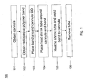
- a method 100 for applying a radiopaque marker to cannula used in a medical device, such as an intracardiac pump.
- Figs. 2A-2E illustrate the method steps for an exemplary embodiment.
- Each of Figs. 2A-2E show a cross section of the cannula corresponding to a plane the slices through the cannula and includes a central axis of the cannula running from an inflow end at the left side of the figure to an outflow end at the right side of the figure.
- a cannula is obtained.
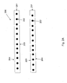
- Fig. 2A shows an example of a cannula 200.
- the cannula 200 includes a tubular wall 201 reinforced by a shape memory structure 202 (as shown, a nitinol coil).
- the tubular wall is flexible, and may be formed of a polymer material, such as polyurethane (PU).
- PU polyurethane
- the cannula 200 advantageously provides a high degree of strength, flexibility and shape memory properties.
- the cannula 200 may be formed using a controlled solution casting process, resulting in a well controlled inner diameter (ID) and outer diameter (OD) of the cannula 200
- ID inner diameter
- OD outer diameter
- the inner surface 203 and outer surface 204 of the tubular wall 201 may be very smooth.
- the surfaces may be substantially free of any variations, features, rough portions, etc. that could promote haemolysis or thrombus during use of the cannula in an implantation procedure.
- a radiopaque polymer band 205 is obtained.
- the band may be formed of a mixture of non-radiopaque or only weakly radiopaque polymer material (e.g., PU) and a radiopaque material (e.g., tungsten).
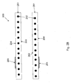
- the band 205 is placed around the outer surface 204 of the cannula 200.
- the band 205 may be thin along the direction normal to the outer surface 203 of the cannula 200.
- the thickness of the band along this direction may be less than 1%, less than 0.1%, less than 0.001 %, of the OD of the cannula 200 (e.g., in the range of 0.001 % to 1.0% of the OD, or any subrange thereof).
- the band may be made of non-radiopaque or only weakly radiopaque polymer material heavily loaded with radiopaque material, in order to ensure that the band is radiopaque despite its thinness.
- a tube 206 of heat shrink material is placed around both the band 205 and the cannula 200.
- the heat shrink tube 206 may be made of any suitable heat shrink material know in the art, including, for example, fluorinated ethylene-propylene (FEP) or polytetrafluoroethylene (PTFE).
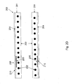
- step 105 heat is applied to the heat shrink tube 206 and the band 205, e.g., by placing the structure shown in Fig. 2C in an oven.
- the band 205 is heated to a temperature above its softening point.
- the heat shrink tube 206 shrinks in response to the heat, applying a force on the softened band 205 in the direction towards the cannula 200.
- the softened band is thereby welded onto the outer surface 204 of the cannula 200, to form a radiopaque marker 210 as shown in Fig, 2D .
- step 106 after the cannula 200 is allowed to cool, the heat shrink tube 206 is removed, exposing the outer surface 204 of the cannula 200, as shown in Fig. 2E .
- the heat shrink tube 206 acts as a mold, ensuring that the portion of the outer surface 204 of the cannula 200 that includes the marker 210 is substantially smooth. In some embodiments, this smooth surface is substantially free of any variations, features, rough portions, etc. that could promote haemolysis or thrombus during use of the cannula in an implantation procedure.
- the outer diameter of the cannula at portion of the outer surface 204 that includes the marker 210 is the same as or substantially the substantially the same as the adjacent portions that do not include the marker 210.
- the use of the heat shrink tubing 206 may ensure that the marker 210 is formed flush with the outer surface of the remainder of the cannula 200.
- the cannula 200 may be mounted on a mandrel or other support structure which maintains the ID of the cannula 200.
- the outer diameter of the portion of the cannula 200 including the radiopaque marker 210 varies from the outer diameter of the adjacent portion without the marker by less than 5%, 1%, 0.1 %, 0.01% or less, (e.g. in the range of 0.001 % to 10% or any subrange thereof.).
- the heating temperature and time for step 105 may be chosen based on the particular materials used and the application at hand.
- cannula 200 may be formed as a nitinol supported PU tube.
- the band 205 may be formed of tungsten loaded PU (e.g., having at least 80% tungsten by weight), and the heat shrink tube may be made of FEP heat shrink tubing.
- a suitable heating step may include baking at about 183 °C for about 3.5 minutes.
- the cannula 200 undergoes a bending process to obtain a desired cannula shape.
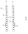
- Fig. 3 illustrates an exemplary process 300 for making a radiopaque band 205 of the type described above.
- a non-radiopaque material is mixed with a radiopaque material.
- the non-radiopaque material may include, e.g. a plastic or polymer.
- PU may be used.
- the radiopaque material may include e.g. a metallic powder such as a tungsten powder.
- other radiopaque materials may be used (e.g. silver, tantalum, tin, etc.).
- the mixing is performed using twin screw extruder device.
- step 302 the mixture is formed into a tube, e.g., using extrusion or any other suitable process known in the art.
- extrusion is performed using twin screw extruder device.
- each band 205 has a width in the range of 1 mm to 2 mm and an outer diameter of about 4 mm (e.g., corresponding the diameter of a cannula having a size of about 12 Fr on the familiar French catheter size scale).
- FIG. 4 another method 400 is disclosed for applying a radiopaque marker to a cannula in a medical device, such as an intracardiac pump.
- Figs. 5A-5D illustrate the method steps for an exemplary embodiment.
- Each of Figs. 5A-5D show a cross section of the cannula corresponding to a plane the slices through the cannula and includes a central axis of the cannula running from an inflow end at the left side of the figure to an outflow end at the right side of the figure.
- a cannula 200 is obtained, as shown in Fig. 5A .
- the cannula 200 may be of the type described above with reference to Figs. 1 and 2A-2E .
- a radiopaque element 505 is obtained.
- the element 505 is a metallic element, e.g., made of tungsten, silver, tantalum, tin or any other suitable material.
- the radiopaque element 505 is placed on the outer surface 204 of the cannula 200.
- the element 505 may be a C-shaped elastic metallic ring (i.e., a ring with a gap) that clamps on to the cannula 200 (e.g., similar to a familiar C-clamp).
- C-shaped elastic metallic ring i.e., a ring with a gap
- other suitable shapes may be used for element 505.
- a sleeve 506 is placed over the radiopaque element 505 on the cannula 200.
- the sleeve 506 may, for example, be made of a plastic or polymer or other material. In some embodiments, the sleeve 506 is made of a non-radiopaque or weakly radiopaque material.
- a heat shrink tube 507 is place over the sleeve 506 and radiopaque element 505 on the cannula 200.
- the heat shrink tube 507 may be made of any suitable heat shrink material know in the art, including, for example, fluorinated ethelyne-propylene (FEP) or polytetrafluoroethylene (PTFE).
- step 406 heat is applied to the heat shrink tube 507 and the sleeve 506, e.g., by placing the structure shown in Fig. 5D in an oven.
- the sleeve 506 is heated to a temperature above its softening point.
- the heat shrink tube 507 shrinks in response to the heat, applying a force on the softened sheath 507 in the direction towards the cannula 200.
- the softened sleeve 506 is thereby welded onto the outer surface 204 of the cannula 200, while forming around the radiopaque element 505.
- the radiopaque element is thereby attached to the cannula 200 to form a radiopaque marker 510.
- the sleeve 506 completely covers the element 505, e.g., so that no surfaces or edges of the element are exposed.
- step 407 after the cannula 200 is allowed to cool, the heat shrink tube 507 is removed, exposing the outer surface 204 of the cannula 200, as shown in Fig. 5E.
- the heat shrink tube 507 acts as a mold, so that the portion of the outer surface 204 of the cannula 200 overlaying the element 505 is smooth.
- this smooth surface is substantially free of any variations, features, rough portions, etc. that could promote haemolysis or thrombus during use of the cannula in an implantation procedure.
- the outer diameter of the cannula at portion of the outer surface 204 that includes the marker 510 is the same as or substantially the substantially the same as the adjacent portions that do not include the marker 210.
- the use of the heat shrink tubing 507 may cause the element 505 to be embedded in the cannula 200 such that the marker 210 is formed flush with the outer surface of the remainder of the cannula 200.
- the radiopaque element 550 is not fully embedded in the cannula 200.
- the welded sleeve 506 forms a smooth covering over the element 505, such that no sharp edges are exposed.
- the outer diameter of the portion of the cannula 200 including the radiopaque marker 510 varies from the outer diameter of the adjacent portion without the marker by less than 5%, 1%, 0.1%, 0.01% or less, (e.g. in the range of 0.001% to 10% or any subrange thereof.).
- the cannula 200 may be mounted on a mandrel or other support structure which maintains the ID of the cannula.
- the cannula 200 undergoes a bending process to obtain a desired cannula shape.
- a cannula with a radiopaque marker of the type described herein my be used in any of a wide variety of medical devices, including intracardiac blood pumps.
- the cannula may advantageously have a small outer diameter, and a smooth surface, suitable for use in intravascular blood pumps.
- the cannula may be incorporated in devices of the types described in any of the references found in the background section above.
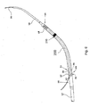
- Fig. 6 illustrates the uses of a cannula 200 including a radiopaque marker 210 of the type described above in an intracranial pump device.
- the pump device may is of the type described in U.S. Pat. Pub. No. 2008/0086027 published April 10, 2008 .
- the intracardiac pump device includes a drive portion 10 and a pump portion 11 coaxial thereto.
- the drive portion 10 includes a motor (not illustrated).
- the proximal end of the drive portion 10 is connected with a catheter 12 holding the electric lines for operating and controlling the blood pump.
- the pump portion 11 is connected with a cannula 200 in the form of an elongate flexible hose whose distal end is provided with a suction head 14 having inflow openings 15.
- Contiguous to the suction head 14 is a soft elastic extension 16 that mechanically, yet not hydraulically extends the cannula 200.
- This extension 16 is provided with a pigtail tip to allow for atraumatic support on body tissue.
- the pump portion 11 has a pump ring 20 that is connected with the drive portion 10 through longitudinally extending webs 21. Between the webs 21, the discharge ports 22 are situated through which blood exits radiallly to then flow along the outer side of the drive portion 10.
- a screen 25 is provided at the pump portion 11. It includes an annular sleeve 26 sitting on the pump ring 20 and a continuously flaring guide portion 27 projecting proximally from the pump ring. The beginning of the guide portion 27 is at the upstream end of the discharge ports 22, i.e. at the end adjoining the pump ring 20.
- the outer diameter of the drive portion 10 and of the pump portion 11 is 4.0 mm.
- the outer diameter of the screen 25 is 5.6 to 6.0 mm.
- the wall thickness of the screen is 0.1 to 0.2 mm.
- the screen is made of a flexible material, for example of polyurethane. It may be formed integral with the cannula 200.
- a guide wire 35 has been inserted through the device for use in positioning the device in a subject (e.g., using the techniques described below with reference to Fig. 7 ).
- Fig. 7 shows a catheter system 700 with an intracardiac blood pump 701.
- the pump 701 includes a cannula with a radiopaque markers of the type described herein.
- the pump 701 may be, for example the Impella 2.5 blood pump available from Abiomed Inc. of Danvers, Ma, modified to include the cannula 200 having a radiopaque marker 210 as described herein.
- the blood pump 701 is a catheter mounted microaxial flow pump capable of pumping up to, e.g., 2.5 L/min of blood from the left ventricle to the systemic circulation.
- the blood pump 701 is placed via a femoral arterial sheath 703 (e.g., a 13 Fr sheath).
- the blood pump includes a cannula 200 featuring a radiopaque marker 210.
- the cannula portion of the device which, during use, sits across the aortic valve is contiguous to and integrated motor 704 that comprises the largest diameter section of the catheter (e.g., at 12 Fr).
- a repositioning device 705 allows removal of the sheath 703 after placement, leaving the modest (e.g.
- the pump 701 is powered and controlled by a control console (not shown), e.g., an Impella series control panel available from Abiomed Inc. of Danvers, Ma.
- a control console e.g., an Impella series control panel available from Abiomed Inc. of Danvers, Ma.
- An arterial infusion pump (not shown) controls a purge system designed to keep the corrosive plasma from entering the motor compartment of the pump 701.
- the pump 701 is inserted via a modified monorail technique under direct fluoroscopic control, pressure monitoring using a pressure lumen 708 adjacent to the motor as well as motor current monitoring are used to give positioning verification to the operator.
- the device is placed using fluoroscopic control to avoid kinking the catheter and compromising the purge lumen. After arterial access is obtained, the 13 F peel-away sheath is positioned.
- a coronary guiding catheter e.g., a JR-4 cathether
- a 0,4572 mm (0.018”) wire is placed across the aortic valve into the left ventricle. Once the 0,4572 mm (0.018”) wire is across the aortic valve, the guiding catheter is removed and the pump catheter is threaded onto the 0.018" wire.
- the wire is removed and the pump 701 activated at minimum level, just enough to counteract the regurgitation coming down the cannula from the proximal aorta into the ventricle now that the cannula is placed across the aortic valve.
- the control panel can be utilized to confirm that the device placement is proper and stable. At this point, the device performance level is typically adjusted to a higher performance level.
- the radiopaque marker 210 on the cannula 200 may be used to assist the practitioner in placement of the pump 701.
- Fig. 8 shows an illustration of a fluoroscopic of the pump 701, during insertion. The radiopaque marker 801 is clearly visible.
- the radiopaque markers described herein have sufficient radiopacity to be clearly visible under conventional fluoroscopic conditions.
- inventive embodiments are presented by way of example only and that, within the scope of the appended claims and equivalents thereto, inventive embodiments may be practiced otherwise than as specifically described and claimed.
- inventive embodiments of the present disclosure are directed to each individual feature, system, article, material, kit, and/or method described herein.
- the above-described embodiments can be implemented in any of numerous ways.
- the embodiments may be implemented using hardware, software or a combination thereof.
- the software code can be executed on any suitable processor or collection of processors, whether provided in a single computer or distributed among multiple computers.
- inventive concepts may be embodied as one or more methods, of which an example has been provided.
- the acts performed as part of the method may be ordered in any suitable way. Accordingly, embodiments may be constructed in which acts are performed in an order different than illustrated, which may include performing some acts simultaneously, even though shown as sequential acts in illustrative embodiments.
- a reference to "A or B", when used in conjunction with open-ended language such as “including” can refer, in one embodiment, to A only (optionally including elements other than B); in another embodiment, to B only (optionally including elements other than A); in yet another embodiment, to both A and B (optionally including other elements); etc.
Landscapes
- Health & Medical Sciences (AREA)
- Engineering & Computer Science (AREA)
- Heart & Thoracic Surgery (AREA)
- Life Sciences & Earth Sciences (AREA)
- Veterinary Medicine (AREA)
- Public Health (AREA)
- Biomedical Technology (AREA)
- Hematology (AREA)
- Anesthesiology (AREA)
- Animal Behavior & Ethology (AREA)
- General Health & Medical Sciences (AREA)
- Mechanical Engineering (AREA)
- Cardiology (AREA)
- Vascular Medicine (AREA)
- Biophysics (AREA)
- Pulmonology (AREA)
- Surgical Instruments (AREA)
- External Artificial Organs (AREA)
Applications Claiming Priority (2)
| Application Number | Priority Date | Filing Date | Title |
|---|---|---|---|
| US41874310P | 2010-12-01 | 2010-12-01 | |
| PCT/US2011/062664 WO2012075152A1 (en) | 2010-12-01 | 2011-11-30 | Radiopaque cannula marker |
Publications (2)
| Publication Number | Publication Date |
|---|---|
| EP2646099A1 EP2646099A1 (en) | 2013-10-09 |
| EP2646099B1 true EP2646099B1 (en) | 2015-04-08 |
Family
ID=46162846
Family Applications (1)
| Application Number | Title | Priority Date | Filing Date |
|---|---|---|---|
| EP11793639.3A Active EP2646099B1 (en) | 2010-12-01 | 2011-11-30 | Radiopaque cannula marker |
Country Status (7)
| Country | Link |
|---|---|
| US (1) | US8795576B2 (enExample) |
| EP (1) | EP2646099B1 (enExample) |
| JP (1) | JP5671627B2 (enExample) |
| AU (1) | AU2011336644B2 (enExample) |
| CA (1) | CA2819641C (enExample) |
| ES (1) | ES2536303T3 (enExample) |
| WO (1) | WO2012075152A1 (enExample) |
Families Citing this family (55)
| Publication number | Priority date | Publication date | Assignee | Title |
|---|---|---|---|---|
| US7393181B2 (en) | 2004-09-17 | 2008-07-01 | The Penn State Research Foundation | Expandable impeller pump |
| AU2007230945B2 (en) | 2006-03-23 | 2013-05-02 | The Penn State Research Foundation | Heart assist device with expandable impeller pump |
| WO2012094641A2 (en) | 2011-01-06 | 2012-07-12 | Thoratec Corporation | Percutaneous heart pump |
| US9827357B2 (en) | 2011-12-03 | 2017-11-28 | Indiana University Research And Technology Corporation | Cavopulmonary viscous impeller assist device and method |
| US9872947B2 (en) | 2012-05-14 | 2018-01-23 | Tc1 Llc | Sheath system for catheter pump |
| US9446179B2 (en) | 2012-05-14 | 2016-09-20 | Thoratec Corporation | Distal bearing support |
| US8721517B2 (en) | 2012-05-14 | 2014-05-13 | Thoratec Corporation | Impeller for catheter pump |
| GB2504176A (en) | 2012-05-14 | 2014-01-22 | Thoratec Corp | Collapsible impeller for catheter pump |
| US9327067B2 (en) | 2012-05-14 | 2016-05-03 | Thoratec Corporation | Impeller for catheter pump |
| GB2504177B (en) | 2012-05-14 | 2014-12-10 | Thoratec Corp | Sheath system for catheter pump |
| EP4186557A1 (en) | 2012-07-03 | 2023-05-31 | Tc1 Llc | Motor assembly for catheter pump |
| US9358329B2 (en) | 2012-07-03 | 2016-06-07 | Thoratec Corporation | Catheter pump |
| US9421311B2 (en) | 2012-07-03 | 2016-08-23 | Thoratec Corporation | Motor assembly for catheter pump |
| US11033728B2 (en) | 2013-03-13 | 2021-06-15 | Tc1 Llc | Fluid handling system |
| WO2014164136A1 (en) | 2013-03-13 | 2014-10-09 | Thoratec Corporation | Fluid handling system |
| US11077294B2 (en) | 2013-03-13 | 2021-08-03 | Tc1 Llc | Sheath assembly for catheter pump |
| EP2968742B1 (en) | 2013-03-15 | 2020-12-02 | Tc1 Llc | Catheter pump assembly including a stator |
| US9308302B2 (en) | 2013-03-15 | 2016-04-12 | Thoratec Corporation | Catheter pump assembly including a stator |
| EP4417244A3 (en) | 2014-04-15 | 2024-10-16 | Tc1 Llc | Catheter pump introducer system |
| WO2015160943A1 (en) | 2014-04-15 | 2015-10-22 | Thoratec Corporation | Sensors for catheter pumps |
| US10583232B2 (en) | 2014-04-15 | 2020-03-10 | Tc1 Llc | Catheter pump with off-set motor position |
| US10363349B2 (en) | 2014-04-15 | 2019-07-30 | Tc1 Llp | Heart pump providing adjustable outflow |
| WO2015160979A1 (en) | 2014-04-15 | 2015-10-22 | Thoratec Corporation | Catheter pump with access ports |
| WO2016028644A1 (en) | 2014-08-18 | 2016-02-25 | Thoratec Corporation | Guide features for percutaneous catheter pump |
| WO2016053688A1 (en) | 2014-10-01 | 2016-04-07 | Heartware, Inc. | Backup controller system with updating |
| WO2016118784A1 (en) | 2015-01-22 | 2016-07-28 | Thoratec Corporation | Attachment mechanisms for motor of catheter pump |
| WO2016118777A1 (en) | 2015-01-22 | 2016-07-28 | Thoratec Corporation | Reduced rotational mass motor assembly for catheter pump |
| WO2016118781A2 (en) | 2015-01-22 | 2016-07-28 | Thoratec Corporation | Motor assembly with heat exchanger for catheter pump |
| US9907890B2 (en) | 2015-04-16 | 2018-03-06 | Tc1 Llc | Catheter pump with positioning brace |
| US9821146B2 (en) | 2015-09-22 | 2017-11-21 | Abiomed, Inc. | Guidewire for cannula placement |
| EP3202433A1 (de) | 2016-02-04 | 2017-08-09 | Berlin Heart GmbH | Auslassgraft sowie system umfassend eine blutpumpe und einen auslassgraft |
| EP3808401A1 (en) | 2016-07-21 | 2021-04-21 | Tc1 Llc | Gas-filled chamber for catheter pump motor assembly |
| EP3808403A1 (en) | 2016-07-21 | 2021-04-21 | Tc1 Llc | Fluid seals for catheter pump motor assembly |
| US10478542B2 (en) | 2017-03-20 | 2019-11-19 | Abiomed, Inc. | Cannula having nitinol reinforced inflow region |
| EP4732889A2 (en) | 2017-06-07 | 2026-04-29 | Supira Medical, Inc. | Intravascular fluid movement devices, systems, and methods of use |
| US11511103B2 (en) | 2017-11-13 | 2022-11-29 | Shifamed Holdings, Llc | Intravascular fluid movement devices, systems, and methods of use |
| CN109985304A (zh) * | 2017-12-29 | 2019-07-09 | 东莞科威医疗器械有限公司 | 医用插管及其成型工艺 |
| JP7410034B2 (ja) | 2018-02-01 | 2024-01-09 | シファメド・ホールディングス・エルエルシー | 血管内血液ポンプならびに使用および製造の方法 |
| WO2020028537A1 (en) | 2018-07-31 | 2020-02-06 | Shifamed Holdings, Llc | Intravascaular blood pumps and methods of use |
| WO2020073047A1 (en) | 2018-10-05 | 2020-04-09 | Shifamed Holdings, Llc | Intravascular blood pumps and methods of use |
| JP7578628B2 (ja) | 2019-06-28 | 2024-11-06 | アビオメド インコーポレイテッド | 二重熱成形カニューレ |
| WO2021011473A1 (en) | 2019-07-12 | 2021-01-21 | Shifamed Holdings, Llc | Intravascular blood pumps and methods of manufacture and use |
| US11654275B2 (en) | 2019-07-22 | 2023-05-23 | Shifamed Holdings, Llc | Intravascular blood pumps with struts and methods of use and manufacture |
| EP4010046A4 (en) | 2019-08-07 | 2023-08-30 | Calomeni, Michael | Catheter blood pumps and collapsible pump housings |
| EP4034192B1 (en) | 2019-09-25 | 2025-12-24 | Supira Medical, Inc. | Intravascular blood pump systems and methods of use and control thereof |
| EP4034221B1 (en) | 2019-09-25 | 2024-11-13 | Shifamed Holdings, LLC | Catheter blood pumps and collapsible pump housings |
| WO2021062260A1 (en) | 2019-09-25 | 2021-04-01 | Shifamed Holdings, Llc | Catheter blood pumps and collapsible blood conduits |
| EP4072650A4 (en) | 2019-12-11 | 2024-01-10 | Shifamed Holdings, LLC | Descending aorta and vena cava blood pumps |
| US12599758B2 (en) | 2019-12-19 | 2026-04-14 | Shifamed Holdings, Llc | Intravascular blood pumps, motors, and fluid control |
| US11911602B2 (en) | 2021-04-22 | 2024-02-27 | Board Of Regents, The University Of Texas System | Method and apparatus for assisting a heart |
| US11918799B2 (en) | 2021-04-22 | 2024-03-05 | Board Of Regents, The University Of Texas System | Method and apparatus for assisting a heart |
| CN113368326B (zh) * | 2021-06-04 | 2022-08-05 | 中国医学科学院阜外医院深圳医院(深圳市孙逸仙心血管医院) | 用于体外心室辅助系统的主动脉插管 |
| JP2024525097A (ja) | 2021-07-07 | 2024-07-09 | エフビーアール メディカル, インク. | 部分的に変形可能なインペラ及び同インペラを組み込んだカテーテル血液ポンプ |
| WO2023007347A1 (en) * | 2021-07-28 | 2023-02-02 | Ethicon, Inc. | Methods of making catheters having visible markers for identifying soaker regions containing fluid openings |
| JP2025172241A (ja) * | 2022-09-30 | 2025-11-21 | テルモ株式会社 | カテーテルおよびカテーテルへのマーカー部材の固定方法 |
Family Cites Families (20)
| Publication number | Priority date | Publication date | Assignee | Title |
|---|---|---|---|---|
| US6123725A (en) * | 1997-07-11 | 2000-09-26 | A-Med Systems, Inc. | Single port cardiac support apparatus |
| DE19821307C1 (de) | 1998-05-13 | 1999-10-21 | Impella Cardiotech Gmbh | Intrakardiale Blutpumpe |
| US6210396B1 (en) * | 1999-06-24 | 2001-04-03 | Medtronic, Inc. | Guiding catheter with tungsten loaded band |
| DE29921352U1 (de) | 1999-12-04 | 2001-04-12 | Impella Cardiotechnik AG, 52074 Aachen | Intravasale Blutpumpe |
| US6520934B1 (en) * | 1999-12-29 | 2003-02-18 | Advanced Cardiovascular Systems, Inc. | Catheter assemblies with flexible radiopaque marker |
| DE10040403A1 (de) | 2000-08-18 | 2002-02-28 | Impella Cardiotech Ag | Intrakardiale Blutpumpe |
| DE10059714C1 (de) | 2000-12-01 | 2002-05-08 | Impella Cardiotech Ag | Intravasale Pumpe |
| US7879024B2 (en) * | 2003-06-26 | 2011-02-01 | St. Jude Medical, Atrial Fibrillation Division, Inc. | Splittable cannula having radiopaque marker |
| DE10336902C5 (de) | 2003-08-08 | 2019-04-25 | Abiomed Europe Gmbh | Intrakardiale Pumpvorrichtung |
| US20050065434A1 (en) * | 2003-09-22 | 2005-03-24 | Bavaro Vincent P. | Polymeric marker with high radiopacity for use in medical devices |
| DE102004049986A1 (de) | 2004-10-14 | 2006-04-20 | Impella Cardiosystems Gmbh | Intrakardiale Blutpumpe |
| EP1847288A4 (en) | 2005-02-10 | 2012-04-11 | Kaneka Corp | MEDICAL CATHETER HOSE AND MANUFACTURING METHOD THEREFOR |
| US20070124161A1 (en) * | 2005-11-09 | 2007-05-31 | Rockwell Electronic Commerce Technologies, Inc. | Method of evaluating contact center performance |
| EP1825872A3 (en) * | 2006-02-23 | 2007-10-03 | Levitronix LLC | A pump-inflow-cannula, a pump-outflow-cannula and a blood managing system |
| US20080027411A1 (en) * | 2006-04-21 | 2008-01-31 | Abbott Laboratories | Guidewire placement device |
| EP2061531B1 (en) * | 2006-09-14 | 2016-04-13 | CircuLite, Inc. | Intravascular blood pump and catheter |
| US7967807B2 (en) * | 2007-03-16 | 2011-06-28 | Medtronic Vascular, Inc. | Vascular fluoroscopic marker |
| US8545548B2 (en) * | 2007-03-30 | 2013-10-01 | DePuy Synthes Products, LLC | Radiopaque markers for implantable stents and methods for manufacturing the same |
| JP2008307093A (ja) * | 2007-06-12 | 2008-12-25 | Goodman Co Ltd | カテーテル及びその製造方法 |
| US7871414B2 (en) * | 2007-12-28 | 2011-01-18 | Wilson-Cook Medical Inc. | Loop tip wire guide with outer sleeve |
-
2011
- 2011-11-30 CA CA2819641A patent/CA2819641C/en active Active
- 2011-11-30 EP EP11793639.3A patent/EP2646099B1/en active Active
- 2011-11-30 ES ES11793639.3T patent/ES2536303T3/es active Active
- 2011-11-30 US US13/307,998 patent/US8795576B2/en active Active
- 2011-11-30 AU AU2011336644A patent/AU2011336644B2/en active Active
- 2011-11-30 WO PCT/US2011/062664 patent/WO2012075152A1/en not_active Ceased
- 2011-11-30 JP JP2013542140A patent/JP5671627B2/ja active Active
Also Published As
| Publication number | Publication date |
|---|---|
| WO2012075152A1 (en) | 2012-06-07 |
| EP2646099A1 (en) | 2013-10-09 |
| JP2014500093A (ja) | 2014-01-09 |
| US20120142995A1 (en) | 2012-06-07 |
| ES2536303T3 (es) | 2015-05-22 |
| AU2011336644A1 (en) | 2013-07-11 |
| AU2011336644B2 (en) | 2015-08-06 |
| CA2819641C (en) | 2015-10-20 |
| US8795576B2 (en) | 2014-08-05 |
| JP5671627B2 (ja) | 2015-02-18 |
| CA2819641A1 (en) | 2012-06-07 |
Similar Documents
| Publication | Publication Date | Title |
|---|---|---|
| EP2646099B1 (en) | Radiopaque cannula marker | |
| EP2874690B1 (en) | Guide extension catheter | |
| KR102429803B1 (ko) | 캐뉼러 배치를 위한 가이드 와이어 | |
| EP2776108B1 (en) | Guide extension catheter | |
| EP3528885B1 (en) | Guide extension catheter | |
| AU2013215036B2 (en) | Guide extension catheter | |
| JP4579910B2 (ja) | デュロメーターが変化する可撓性の挿入器シース | |
| US7850623B2 (en) | Elongate medical device with continuous reinforcement member | |
| CA2819593C (en) | Loading guide lumen | |
| EP3074079B1 (en) | Medical devices for accessing body lumens | |
| EP1712247B1 (en) | Catheter | |
| US20140052097A1 (en) | Guide extension catheter | |
| US20100160953A1 (en) | Introducer sheath for use with an embolic coil device and methods for making and using the same | |
| JP2019506241A (ja) | 縮小された外形を有するステント送達システム | |
| US20250134530A1 (en) | Delivery device for occlusive implants | |
| US20250025179A1 (en) | Delivery device for occlusive implants |
Legal Events
| Date | Code | Title | Description |
|---|---|---|---|
| PUAI | Public reference made under article 153(3) epc to a published international application that has entered the european phase |
Free format text: ORIGINAL CODE: 0009012 |
|
| 17P | Request for examination filed |
Effective date: 20130625 |
|
| AK | Designated contracting states |
Kind code of ref document: A1 Designated state(s): AL AT BE BG CH CY CZ DE DK EE ES FI FR GB GR HR HU IE IS IT LI LT LU LV MC MK MT NL NO PL PT RO RS SE SI SK SM TR |
|
| DAX | Request for extension of the european patent (deleted) | ||
| GRAP | Despatch of communication of intention to grant a patent |
Free format text: ORIGINAL CODE: EPIDOSNIGR1 |
|
| INTG | Intention to grant announced |
Effective date: 20141029 |
|
| GRAS | Grant fee paid |
Free format text: ORIGINAL CODE: EPIDOSNIGR3 |
|
| GRAA | (expected) grant |
Free format text: ORIGINAL CODE: 0009210 |
|
| AK | Designated contracting states |
Kind code of ref document: B1 Designated state(s): AL AT BE BG CH CY CZ DE DK EE ES FI FR GB GR HR HU IE IS IT LI LT LU LV MC MK MT NL NO PL PT RO RS SE SI SK SM TR |
|
| REG | Reference to a national code |
Ref country code: GB Ref legal event code: FG4D |
|
| REG | Reference to a national code |
Ref country code: CH Ref legal event code: EP |
|
| REG | Reference to a national code |
Ref country code: IE Ref legal event code: FG4D |
|
| REG | Reference to a national code |
Ref country code: SE Ref legal event code: TRGR |
|
| REG | Reference to a national code |
Ref country code: AT Ref legal event code: REF Ref document number: 720054 Country of ref document: AT Kind code of ref document: T Effective date: 20150515 |
|
| REG | Reference to a national code |
Ref country code: DE Ref legal event code: R096 Ref document number: 602011015549 Country of ref document: DE Effective date: 20150521 |
|
| REG | Reference to a national code |
Ref country code: ES Ref legal event code: FG2A Ref document number: 2536303 Country of ref document: ES Kind code of ref document: T3 Effective date: 20150522 |
|
| REG | Reference to a national code |
Ref country code: AT Ref legal event code: MK05 Ref document number: 720054 Country of ref document: AT Kind code of ref document: T Effective date: 20150408 |
|
| REG | Reference to a national code |
Ref country code: NL Ref legal event code: VDEP Effective date: 20150408 |
|
| REG | Reference to a national code |
Ref country code: LT Ref legal event code: MG4D |
|
| PG25 | Lapsed in a contracting state [announced via postgrant information from national office to epo] |
Ref country code: NL Free format text: LAPSE BECAUSE OF FAILURE TO SUBMIT A TRANSLATION OF THE DESCRIPTION OR TO PAY THE FEE WITHIN THE PRESCRIBED TIME-LIMIT Effective date: 20150408 |
|
| PG25 | Lapsed in a contracting state [announced via postgrant information from national office to epo] |
Ref country code: NO Free format text: LAPSE BECAUSE OF FAILURE TO SUBMIT A TRANSLATION OF THE DESCRIPTION OR TO PAY THE FEE WITHIN THE PRESCRIBED TIME-LIMIT Effective date: 20150708 Ref country code: FI Free format text: LAPSE BECAUSE OF FAILURE TO SUBMIT A TRANSLATION OF THE DESCRIPTION OR TO PAY THE FEE WITHIN THE PRESCRIBED TIME-LIMIT Effective date: 20150408 Ref country code: HR Free format text: LAPSE BECAUSE OF FAILURE TO SUBMIT A TRANSLATION OF THE DESCRIPTION OR TO PAY THE FEE WITHIN THE PRESCRIBED TIME-LIMIT Effective date: 20150408 Ref country code: PT Free format text: LAPSE BECAUSE OF FAILURE TO SUBMIT A TRANSLATION OF THE DESCRIPTION OR TO PAY THE FEE WITHIN THE PRESCRIBED TIME-LIMIT Effective date: 20150810 Ref country code: LT Free format text: LAPSE BECAUSE OF FAILURE TO SUBMIT A TRANSLATION OF THE DESCRIPTION OR TO PAY THE FEE WITHIN THE PRESCRIBED TIME-LIMIT Effective date: 20150408 |
|
| REG | Reference to a national code |
Ref country code: FR Ref legal event code: PLFP Year of fee payment: 5 |
|
| PG25 | Lapsed in a contracting state [announced via postgrant information from national office to epo] |
Ref country code: LV Free format text: LAPSE BECAUSE OF FAILURE TO SUBMIT A TRANSLATION OF THE DESCRIPTION OR TO PAY THE FEE WITHIN THE PRESCRIBED TIME-LIMIT Effective date: 20150408 Ref country code: RS Free format text: LAPSE BECAUSE OF FAILURE TO SUBMIT A TRANSLATION OF THE DESCRIPTION OR TO PAY THE FEE WITHIN THE PRESCRIBED TIME-LIMIT Effective date: 20150408 Ref country code: IS Free format text: LAPSE BECAUSE OF FAILURE TO SUBMIT A TRANSLATION OF THE DESCRIPTION OR TO PAY THE FEE WITHIN THE PRESCRIBED TIME-LIMIT Effective date: 20150808 Ref country code: GR Free format text: LAPSE BECAUSE OF FAILURE TO SUBMIT A TRANSLATION OF THE DESCRIPTION OR TO PAY THE FEE WITHIN THE PRESCRIBED TIME-LIMIT Effective date: 20150709 Ref country code: AT Free format text: LAPSE BECAUSE OF FAILURE TO SUBMIT A TRANSLATION OF THE DESCRIPTION OR TO PAY THE FEE WITHIN THE PRESCRIBED TIME-LIMIT Effective date: 20150408 |
|
| REG | Reference to a national code |
Ref country code: DE Ref legal event code: R097 Ref document number: 602011015549 Country of ref document: DE |
|
| PG25 | Lapsed in a contracting state [announced via postgrant information from national office to epo] |
Ref country code: EE Free format text: LAPSE BECAUSE OF FAILURE TO SUBMIT A TRANSLATION OF THE DESCRIPTION OR TO PAY THE FEE WITHIN THE PRESCRIBED TIME-LIMIT Effective date: 20150408 Ref country code: DK Free format text: LAPSE BECAUSE OF FAILURE TO SUBMIT A TRANSLATION OF THE DESCRIPTION OR TO PAY THE FEE WITHIN THE PRESCRIBED TIME-LIMIT Effective date: 20150408 |
|
| PLBE | No opposition filed within time limit |
Free format text: ORIGINAL CODE: 0009261 |
|
| STAA | Information on the status of an ep patent application or granted ep patent |
Free format text: STATUS: NO OPPOSITION FILED WITHIN TIME LIMIT |
|
| PG25 | Lapsed in a contracting state [announced via postgrant information from national office to epo] |
Ref country code: PL Free format text: LAPSE BECAUSE OF FAILURE TO SUBMIT A TRANSLATION OF THE DESCRIPTION OR TO PAY THE FEE WITHIN THE PRESCRIBED TIME-LIMIT Effective date: 20150408 Ref country code: CZ Free format text: LAPSE BECAUSE OF FAILURE TO SUBMIT A TRANSLATION OF THE DESCRIPTION OR TO PAY THE FEE WITHIN THE PRESCRIBED TIME-LIMIT Effective date: 20150408 Ref country code: SK Free format text: LAPSE BECAUSE OF FAILURE TO SUBMIT A TRANSLATION OF THE DESCRIPTION OR TO PAY THE FEE WITHIN THE PRESCRIBED TIME-LIMIT Effective date: 20150408 Ref country code: RO Free format text: LAPSE BECAUSE OF NON-PAYMENT OF DUE FEES Effective date: 20150408 |
|
| 26N | No opposition filed |
Effective date: 20160111 |
|
| PG25 | Lapsed in a contracting state [announced via postgrant information from national office to epo] |
Ref country code: SI Free format text: LAPSE BECAUSE OF FAILURE TO SUBMIT A TRANSLATION OF THE DESCRIPTION OR TO PAY THE FEE WITHIN THE PRESCRIBED TIME-LIMIT Effective date: 20150408 |
|
| PG25 | Lapsed in a contracting state [announced via postgrant information from national office to epo] |
Ref country code: MC Free format text: LAPSE BECAUSE OF FAILURE TO SUBMIT A TRANSLATION OF THE DESCRIPTION OR TO PAY THE FEE WITHIN THE PRESCRIBED TIME-LIMIT Effective date: 20150408 Ref country code: LU Free format text: LAPSE BECAUSE OF FAILURE TO SUBMIT A TRANSLATION OF THE DESCRIPTION OR TO PAY THE FEE WITHIN THE PRESCRIBED TIME-LIMIT Effective date: 20151130 |
|
| REG | Reference to a national code |
Ref country code: CH Ref legal event code: PL |
|
| PG25 | Lapsed in a contracting state [announced via postgrant information from national office to epo] |
Ref country code: CH Free format text: LAPSE BECAUSE OF NON-PAYMENT OF DUE FEES Effective date: 20151130 Ref country code: LI Free format text: LAPSE BECAUSE OF NON-PAYMENT OF DUE FEES Effective date: 20151130 |
|
| REG | Reference to a national code |
Ref country code: IE Ref legal event code: MM4A |
|
| PG25 | Lapsed in a contracting state [announced via postgrant information from national office to epo] |
Ref country code: BE Free format text: LAPSE BECAUSE OF FAILURE TO SUBMIT A TRANSLATION OF THE DESCRIPTION OR TO PAY THE FEE WITHIN THE PRESCRIBED TIME-LIMIT Effective date: 20150408 |
|
| PG25 | Lapsed in a contracting state [announced via postgrant information from national office to epo] |
Ref country code: IE Free format text: LAPSE BECAUSE OF NON-PAYMENT OF DUE FEES Effective date: 20151130 |
|
| REG | Reference to a national code |
Ref country code: FR Ref legal event code: PLFP Year of fee payment: 6 |
|
| PG25 | Lapsed in a contracting state [announced via postgrant information from national office to epo] |
Ref country code: SM Free format text: LAPSE BECAUSE OF FAILURE TO SUBMIT A TRANSLATION OF THE DESCRIPTION OR TO PAY THE FEE WITHIN THE PRESCRIBED TIME-LIMIT Effective date: 20150408 Ref country code: HU Free format text: LAPSE BECAUSE OF FAILURE TO SUBMIT A TRANSLATION OF THE DESCRIPTION OR TO PAY THE FEE WITHIN THE PRESCRIBED TIME-LIMIT; INVALID AB INITIO Effective date: 20111130 Ref country code: BG Free format text: LAPSE BECAUSE OF FAILURE TO SUBMIT A TRANSLATION OF THE DESCRIPTION OR TO PAY THE FEE WITHIN THE PRESCRIBED TIME-LIMIT Effective date: 20150408 |
|
| PG25 | Lapsed in a contracting state [announced via postgrant information from national office to epo] |
Ref country code: CY Free format text: LAPSE BECAUSE OF FAILURE TO SUBMIT A TRANSLATION OF THE DESCRIPTION OR TO PAY THE FEE WITHIN THE PRESCRIBED TIME-LIMIT Effective date: 20150408 |
|
| PG25 | Lapsed in a contracting state [announced via postgrant information from national office to epo] |
Ref country code: MT Free format text: LAPSE BECAUSE OF FAILURE TO SUBMIT A TRANSLATION OF THE DESCRIPTION OR TO PAY THE FEE WITHIN THE PRESCRIBED TIME-LIMIT Effective date: 20150408 |
|
| REG | Reference to a national code |
Ref country code: FR Ref legal event code: PLFP Year of fee payment: 7 |
|
| PG25 | Lapsed in a contracting state [announced via postgrant information from national office to epo] |
Ref country code: TR Free format text: LAPSE BECAUSE OF FAILURE TO SUBMIT A TRANSLATION OF THE DESCRIPTION OR TO PAY THE FEE WITHIN THE PRESCRIBED TIME-LIMIT Effective date: 20150408 Ref country code: MK Free format text: LAPSE BECAUSE OF FAILURE TO SUBMIT A TRANSLATION OF THE DESCRIPTION OR TO PAY THE FEE WITHIN THE PRESCRIBED TIME-LIMIT Effective date: 20150408 |
|
| PG25 | Lapsed in a contracting state [announced via postgrant information from national office to epo] |
Ref country code: AL Free format text: LAPSE BECAUSE OF FAILURE TO SUBMIT A TRANSLATION OF THE DESCRIPTION OR TO PAY THE FEE WITHIN THE PRESCRIBED TIME-LIMIT Effective date: 20150408 |
|
| REG | Reference to a national code |
Ref country code: DE Ref legal event code: R082 Ref document number: 602011015549 Country of ref document: DE Representative=s name: VENNER SHIPLEY GERMANY LLP, DE Ref country code: DE Ref legal event code: R082 Ref document number: 602011015549 Country of ref document: DE Representative=s name: VENNER SHIPLEY LLP, DE |
|
| PGFP | Annual fee paid to national office [announced via postgrant information from national office to epo] |
Ref country code: FR Payment date: 20250930 Year of fee payment: 15 |
|
| PGFP | Annual fee paid to national office [announced via postgrant information from national office to epo] |
Ref country code: DE Payment date: 20250930 Year of fee payment: 15 |
|
| PGFP | Annual fee paid to national office [announced via postgrant information from national office to epo] |
Ref country code: GB Payment date: 20251001 Year of fee payment: 15 |
|
| PGFP | Annual fee paid to national office [announced via postgrant information from national office to epo] |
Ref country code: IT Payment date: 20251022 Year of fee payment: 15 |
|
| PGFP | Annual fee paid to national office [announced via postgrant information from national office to epo] |
Ref country code: SE Payment date: 20251001 Year of fee payment: 15 |
|
| PGFP | Annual fee paid to national office [announced via postgrant information from national office to epo] |
Ref country code: ES Payment date: 20251212 Year of fee payment: 15 |