EP2645738B1 - Signal processing device, signal processing method, and signal processing program - Google Patents
Signal processing device, signal processing method, and signal processing program Download PDFInfo
- Publication number
- EP2645738B1 EP2645738B1 EP11842999.2A EP11842999A EP2645738B1 EP 2645738 B1 EP2645738 B1 EP 2645738B1 EP 11842999 A EP11842999 A EP 11842999A EP 2645738 B1 EP2645738 B1 EP 2645738B1
- Authority
- EP
- European Patent Office
- Prior art keywords
- noise
- minimum value
- unit
- signal
- input signal
- Prior art date
- Legal status (The legal status is an assumption and is not a legal conclusion. Google has not performed a legal analysis and makes no representation as to the accuracy of the status listed.)
- Active
Links
- 238000012545 processing Methods 0.000 title claims description 32
- 238000003672 processing method Methods 0.000 title claims description 3
- 230000001629 suppression Effects 0.000 claims description 115
- 230000004048 modification Effects 0.000 claims description 26
- 238000012986 modification Methods 0.000 claims description 26
- 238000000034 method Methods 0.000 description 47
- 238000001228 spectrum Methods 0.000 description 42
- 238000004364 calculation method Methods 0.000 description 21
- 238000010586 diagram Methods 0.000 description 15
- 238000009408 flooring Methods 0.000 description 11
- 230000006870 function Effects 0.000 description 10
- 230000008859 change Effects 0.000 description 8
- 238000000605 extraction Methods 0.000 description 8
- 230000003595 spectral effect Effects 0.000 description 7
- 238000005516 engineering process Methods 0.000 description 6
- 230000015572 biosynthetic process Effects 0.000 description 4
- 230000000694 effects Effects 0.000 description 4
- 238000003786 synthesis reaction Methods 0.000 description 4
- 230000009467 reduction Effects 0.000 description 3
- 230000001413 cellular effect Effects 0.000 description 2
- 238000006243 chemical reaction Methods 0.000 description 2
- 239000000284 extract Substances 0.000 description 2
- 230000010354 integration Effects 0.000 description 2
- 239000004065 semiconductor Substances 0.000 description 2
- 230000005534 acoustic noise Effects 0.000 description 1
- 230000006978 adaptation Effects 0.000 description 1
- 238000013459 approach Methods 0.000 description 1
- 238000004891 communication Methods 0.000 description 1
- 230000002596 correlated effect Effects 0.000 description 1
- 238000001514 detection method Methods 0.000 description 1
- 239000006185 dispersion Substances 0.000 description 1
- 230000006872 improvement Effects 0.000 description 1
- 238000012805 post-processing Methods 0.000 description 1
- 238000007781 pre-processing Methods 0.000 description 1
- 230000008569 process Effects 0.000 description 1
- 238000005070 sampling Methods 0.000 description 1
- 238000000926 separation method Methods 0.000 description 1
- 230000005236 sound signal Effects 0.000 description 1
- 238000012546 transfer Methods 0.000 description 1
- 230000009466 transformation Effects 0.000 description 1
- 230000001755 vocal effect Effects 0.000 description 1
Images


Classifications
-
- G—PHYSICS
- G10—MUSICAL INSTRUMENTS; ACOUSTICS
- G10K—SOUND-PRODUCING DEVICES; METHODS OR DEVICES FOR PROTECTING AGAINST, OR FOR DAMPING, NOISE OR OTHER ACOUSTIC WAVES IN GENERAL; ACOUSTICS NOT OTHERWISE PROVIDED FOR
- G10K11/00—Methods or devices for transmitting, conducting or directing sound in general; Methods or devices for protecting against, or for damping, noise or other acoustic waves in general
- G10K11/16—Methods or devices for protecting against, or for damping, noise or other acoustic waves in general
-
- G—PHYSICS
- G10—MUSICAL INSTRUMENTS; ACOUSTICS
- G10L—SPEECH ANALYSIS OR SYNTHESIS; SPEECH RECOGNITION; SPEECH OR VOICE PROCESSING; SPEECH OR AUDIO CODING OR DECODING
- G10L21/00—Processing of the speech or voice signal to produce another audible or non-audible signal, e.g. visual or tactile, in order to modify its quality or its intelligibility
- G10L21/02—Speech enhancement, e.g. noise reduction or echo cancellation
- G10L21/0316—Speech enhancement, e.g. noise reduction or echo cancellation by changing the amplitude
- G10L21/0324—Details of processing therefor
- G10L21/034—Automatic adjustment
-
- H—ELECTRICITY
- H04—ELECTRIC COMMUNICATION TECHNIQUE
- H04R—LOUDSPEAKERS, MICROPHONES, GRAMOPHONE PICK-UPS OR LIKE ACOUSTIC ELECTROMECHANICAL TRANSDUCERS; DEAF-AID SETS; PUBLIC ADDRESS SYSTEMS
- H04R3/00—Circuits for transducers, loudspeakers or microphones
- H04R3/04—Circuits for transducers, loudspeakers or microphones for correcting frequency response
-
- G—PHYSICS
- G10—MUSICAL INSTRUMENTS; ACOUSTICS
- G10L—SPEECH ANALYSIS OR SYNTHESIS; SPEECH RECOGNITION; SPEECH OR VOICE PROCESSING; SPEECH OR AUDIO CODING OR DECODING
- G10L21/00—Processing of the speech or voice signal to produce another audible or non-audible signal, e.g. visual or tactile, in order to modify its quality or its intelligibility
- G10L21/02—Speech enhancement, e.g. noise reduction or echo cancellation
- G10L21/0208—Noise filtering
-
- H—ELECTRICITY
- H04—ELECTRIC COMMUNICATION TECHNIQUE
- H04R—LOUDSPEAKERS, MICROPHONES, GRAMOPHONE PICK-UPS OR LIKE ACOUSTIC ELECTROMECHANICAL TRANSDUCERS; DEAF-AID SETS; PUBLIC ADDRESS SYSTEMS
- H04R2410/00—Microphones
-
- H—ELECTRICITY
- H04—ELECTRIC COMMUNICATION TECHNIQUE
- H04R—LOUDSPEAKERS, MICROPHONES, GRAMOPHONE PICK-UPS OR LIKE ACOUSTIC ELECTROMECHANICAL TRANSDUCERS; DEAF-AID SETS; PUBLIC ADDRESS SYSTEMS
- H04R2499/00—Aspects covered by H04R or H04S not otherwise provided for in their subgroups
- H04R2499/10—General applications
- H04R2499/11—Transducers incorporated or for use in hand-held devices, e.g. mobile phones, PDA's, camera's
Definitions
- the present invention relates to a signal processing technology which processes a signal and obtains a target output.
- a signal processing technology for processing an input signal using a converter device and obtaining a target output is known.
- a noise suppressing technology exists. It suppresses noise in a noisy signal and outputs an enhanced signal.
- the noisy signal is a signal in which noise is superposed on the target signal.
- the enhanced signal is a signal in which the target signal is emphasized.
- a noise suppressor which suppresses noise superposed on a target speech signal is used for various audio terminals such as a cellular phone or like.
- patent document 1 discloses a method to suppress noise by multiplying the suppression coefficient smaller than 1 to an input signal.
- Patent document 2 discloses a method to suppress noise by subtracting presumed noise directly from a noisy signal.
- Patent document 3 discloses a noise suppression system which can realize the sufficient noise suppression effect and the small distortion in the enhanced signal, even when a condition that noise is sufficiently small compared to a target signal is not satisfied.
- Patent document 3 assumes a case when the characteristics of noise mixed in the target signal is known to some extent beforehand.
- the technology described in patent document 3 suppresses noise by subtracting noise information recorded beforehand from a noisy signal.
- noise information is information about characteristics of noise.
- the document US 2007/257840 describes signal processing techniques that can improve the performance of blind source separation (BSS) techniques.
- the described techniques propose pre-processing steps that can help to de-correlate the different signals from one another prior to execution of the BSS techniques.
- the described techniques also propose optional post-processing steps that can further de-correlate the different signals following execution of the BSS techniques.
- the techniques may be particularly useful for improving BSS performance with highly correlated audio signals, e.g., from two microphones that are in close spatial proximity to one another.
- the document EP 2 151 821 relates to a method for signal processing comprising the steps of providing a set of prototype spectral envelopes, providing a set of reference noise prototypes, wherein the reference noise prototypes are obtained from at least a subset of the provided set of prototype spectral envelopes, detecting a verbal utterance by at least one microphone to obtain a microphone signal, processing the microphone signal for noise reduction based on the provided reference noise prototypes to obtain an enhanced signal and encoding the enhanced signal based on the provided prototype spectral envelopes to obtain an encoded enhanced signal.
- the object of the present invention is to provide a signal processing technology which solves the above-mentioned problem.
- an apparatus includes an input means which inputs an input signal through a converter device, a memory means which stores a minimum value of a reference signal inputted through a reference converter device, a comparison means which compares a minimum value of the input signal and the minimum value of the reference signal, and a modification means which modifies the input signal in accordance with the comparison result of the comparison means.
- a method inputs an input signal through a converter device and compares a minimum value of an inputted reference signal and a minimum value of an input signal through a reference converter device, and modifies the input signal in accordance with the comparison result.
- a program stored in a program recording medium makes a computer execute a step which inputs an input signal through a converter device, a step which compares a minimum value of a reference signal inputted through a reference converter device and a minimum value of an input signal, and a step which modifies the input signal in accordance with the comparison result.
- the signal processing technology which compensates output variability caused by the difference in performance of and the individual difference between converter devices, and performs highly-accurate signal processing can be provided.
- a “converter device” in the following description is a so-called transducer.
- the “converter device” is an electric and electronic device or an electric machine which changes a certain kind of energy into another thing for various purposes including measuring and information transfer.
- the “converter device” includes an device or an apparatus which changes a measured value to an electric signal like a sensor and a microphone (hereinafter, mike), for example.
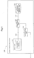
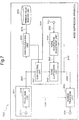
- a signal processing device 100 as a first exemplary embodiment of the present invention will be described using Fig. 1 .
- the signal processing device 100 includes an input unit 101, a reference minimum value memory unit 102, a comparing unit 103 and a modification unit 104.
- the input unit 101 inputs an input signal 120 to the comparing unit 103 and the modification unit 104 through a converter device 111.
- the reference minimum value memory unit 102 stores a minimum value (reference minimum value) of a reference signal inputted through a reference converter device.
- the comparing unit 103 compares a minimum value of the input signal 120 and the reference minimum value.
- the modification unit 104 modifies the input signal 120 in accordance with the comparison result of the comparing unit 103.
- the signal processing device 100 compensates output variability caused by the difference in the performance of and the individual difference between converter devices, and can perform highly-accurate signal processing.
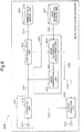
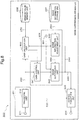
- a noise suppression apparatus 200 As a second exemplary embodiment that realizes a signal processing method according to the present invention, a noise suppression apparatus 200 will be described.
- Fig. 2 is a block diagram showing an entire configuration of the noise suppression apparatus 200.
- the noise suppression apparatus 200 also functions as the part of the apparatus such as a digital camera, a laptop computer and a cellular phone, for example, the present invention is not limited to this.
- the noise suppression apparatus 200 can be applied to all signal processing devices which are required the noise suppression from an input signal.
- the noise suppression apparatus 200 includes an input unit 201, a minimum value memory unit 202, a gain calculation unit 203, a modification unit 204 and an output unit 205.
- the input unit 201 decomposes a speech signal into frequency components and supplies them to the gain calculation unit 203 as a comparison means and the modification unit 204.
- the mike 211 is supplied a noisy signal as a sample value sequence.
- the noisy signal is a signal in which a target signal and noise are intermingled.
- the transform unit 212 When the noisy signal is supplied to the mike 211, the transform unit 212 performs conversion such as Fourier transform to the supplied noisy signal and divides into a plurality of frequency components.
- the transform unit 212 supplies a amplitude spectrum 220 among a plurality of frequency components to the gain calculation unit 203 and a gain control unit 241.
- the transform unit 212 transmits a phase spectrum 230 among a plurality of frequency components to an inverse transform unit 252.
- the gain control unit 241 receives the amplitude spectrum from the transform unit 212.
- the gain control unit 241 multiplies the amplitude spectrum by a gain and supplies the result to a noise suppression unit 242.
- the transform unit 212 supplies the amplitude spectrum 220 to the noise suppression unit 242 via the gain control unit 241, the present invention is not limited to this.
- the transform unit 212 may supply a power spectrum which corresponds to a square of the amplitude spectrum 220 to the noise suppression unit 242 via the gain control unit 241.
- the minimum value memory unit 202 includes a memory device such a semiconductor memory.
- the minimum value memory unit 202 stores a reference minimum value about noise.
- the reference minimum value may be determined by recording only noise which this apparatus tries to suppress in a quiet room with a mike.
- the mike is a mike which becomes the standard as an example of a reference converter device.
- a case when the noise suppression apparatus 200 according to this exemplary embodiment is installed in a digital camera is considered.
- a value in which a standard mike picked up noise which is generated in the state where the digital camera in which the noise suppression apparatus 200 was installed was powered on may be available as the reference minimum value.
- a speech signal for each frequency component is inputted into the noise suppression apparatus 200 from the input unit 201. Therefore, in this exemplary embodiment, it is supposed that a reference minimum value is also prepared for each frequency component.
- the exemplary embodiment of the present invention is not limited to this.
- the gain calculation unit 203 includes a minimum value extraction unit 231.
- the minimum value extraction unit 231 extracts a minimum value of each frequency component of the speech signal outputted from the transform unit 212.
- the gain calculation unit 203 includes a minimum value comparing unit 232.
- the minimum value comparing unit 232 compares the extracted minimum value with the reference minimum value read from the minimum value memory unit 202.
- the gain calculation unit 203 calculates a gain control value (modification factor) for each frequency component which should be applied to an input signal using a ratio of the extracted minimum value and the reference minimum value. For example, the gain calculation unit 203 calculates its gain control value so that the extracted minimum value may be identical to the reference minimum value.
- the minimum value extraction unit 231 analyzes the noisy signal amplitude (or power spectrum) supplied from the transform unit 212 every one sample and derives a minimum value. Or the minimum value extraction unit 231 analyzes the noisy signal amplitude (or power spectrum) every several samples and derives the minimum value. Whenever analyzed, the minimum value extraction unit 231 updates the minimum value and extracts the minimum value in all inputted in the past. That is, the minimum value becomes smaller as the extraction becomes a long time. Specifically, the minimum value extraction unit 231 compares the first minimum value with the second minimum value, for example, and further compares with the third minimum value and updates. Therefore, the minimum value becomes smaller one after another as the sampling becomes a long time.
- the minimum value extraction unit 231 may reset the minimum value for every definite time.
- the minimum value comes to express the minimum component in the noisy signal, so that the interval of the reset becomes long.
- the noisy signal includes a target signal and noise, and the noise has a signal level lower than the target signal, a minimum value of the noisy signal will be the minimum value of the noise.
- the minimum value memory unit 202 stores the minimum value obtained by recording only noise in a quiet environment as a reference minimum value. Accordingly, the gain calculation unit 203 can compare the minimum value of the same noise and get master data of gain control.
- the gain control unit 241 controls a gain based on a gain calculated in the gain calculation unit 203.
- the timing of gain control may be every one sample and may be also every fixed number of samples.
- the noise suppression apparatus 200 may adjust by using the same gain to all frequencies.
- the transform unit 212 may perform gain adjustment with the minimum value before performing the Fourier transform in the transform unit 212.
- a noise information storage unit 207 includes a memory device such a semiconductor memory.
- the noise information storage unit 207 stores noise information (information about characteristics of noise). For example, a shape of a spectrum of noise may be available as the noise information.
- the frequency characteristic of the phase and the feature quantity of the strength and time change in the specific frequency may be also available as the noise information in addition to the shape of the spectrum. Additionally, statistics value (maximum, minimum, dispersion and median) or the like may be also available as the noise information.
- the noise information storage unit 207 stores amplitude (or power) data of 1024.
- a noise information storage unit 207 may store data of a subband which is obtained by integrating a plurality of frequency components instead of the amplitude (or power) data of 1024.
- the noise suppression apparatus 200 can reduce the required memory size and amount of operation.
- the minimum value memory unit 202 stores a minimum value about the respective spectra.
- Noise information recorded in the noise information storage unit 207 is supplied to a noise information adjustment unit 243.
- the noise information adjustment unit 243 modifies the noise information by multiplying the scaling factor and supplies it to the noise suppression unit 242 as modified noise information.
- the noise suppression unit 242 suppresses noise in each frequency using the noisy signal amplitude spectrum supplied from the gain control unit 241 and the modified noise information 260 supplied from the noise information adjustment unit 243.
- the noise suppression unit 242 transmits an enhanced signal amplitude spectrum 240 as the noise suppression result to an inverse transform unit 252.
- the noise suppression unit 242 transmits the enhanced signal amplitude spectrum 240 to the noise information adjustment unit 243.
- the noise information adjustment unit 243 modifies the noise information based on the enhanced signal amplitude spectrum 240 as the noise suppression result.
- the inverse transform unit 252 puts the enhanced signal amplitude spectrum 240 supplied from the noise suppression unit 242 and the phase spectrum 230 of the noisy signal supplied from the transform unit 212 together, and performs inverse transform thereto and supplies it to an output terminal 251 as an enhanced signal sample.
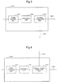
- Fig. 3 is a block diagram showing an internal configuration of the transform unit 212.
- the transform unit 212 includes a frame dividing unit 301, a windowing unit 302 and a Fourier transform unit 303.
- the noisy signal samples are supplied to the frame dividing unit 301 and are divided into a frame for each K/2 sample.
- K is an even number.
- noisy signal samples divided into frames are supplied to the windowing unit 302, and are multiplied by w(t).
- w(t) is a window function.
- the windowing unit 22 may use a symmetrical window function to a real number signal.
- the windowing unit 22 may use a Hanning window indicated by the following equation (3), for example.
- window functions such as Hamming window, Kaiser window and Blackman window are also known.
- the output of windowing is supplied to the Fourier transform unit 303 and is transformed into a noisy signal spectrum Yn(k).
- the noisy signal spectral Yn(k) is separated into a phase and a amplitude, the noisy signal phase spectrum argYn(k) is supplied to the inverse transform unit 252, and the noisy signal amplitude spectrum
- a power spectrum may be used instead of a amplitude spectrum.
- Fig. 4 is a block diagram showing a configuration of the inverse transform unit 252.
- the inverse transform unit 252 includes an inverse Fourier transform unit 403, a windowing unit 402 and a frame synthesis unit 401.
- the inverse Fourier transform unit 403 multiplies the enhanced signal amplitude spectrum 240 supplied from the noise suppression unit 242 by the noisy signal phase spectrum 230 supplied from the transform unit 212, and obtains an enhanced signal (the left-side of the following equation (4)). [Equation 4] .
- X ⁇ n k X ⁇ n k ⁇ arg Y n k
- the inverse Fourier transform unit 403 performs inverse Fourier transform of the obtained enhanced signal.
- x ⁇ n t w t x n t
- the obtained output signal is transmitted from the frame synthesis unit 401 to the output terminal 251. [Equation 7] .
- x ⁇ n t x ⁇ n ⁇ 1 t + K / 2 + x ⁇ n t
- transforms in the transformation unit 212 and the inverse transform unit 252 have been described as a Fourier transform in Fig. 3 and Fig. 4 .
- the transform unit 212 and the inverse transform unit 252 can use another transform such as cosine transform, modified cosine transform, Hadamard transform, Haar transform or wavelet transform in place of Fourier transform.
- cosine transform and modified cosine transform obtain only the amplitude as a transform result. Therefore, a route to the inverse transform unit 252 from the transform unit 212 in FIG. 1 becomes unnecessary.
- noise information to be recorded in the noise information storage unit 207 is only for the amplitude (or power), it contributes to a reduction in memory capacity and a reduction in amount of calculation in the noise suppression processing.
- the transform unit 212 and the inverse transform unit 252 use wavelet transform, the time resolution can be changed to something different by a frequency. Therefore, improvement of a noise suppression effect can be expected.
- the noise suppression unit 242 can perform actual suppression after a plurality of frequency components obtained in the transform unit 212 has been integrated. On this occasion, by integrating more frequency components from low frequency ranges where auditory discrimination capability is higher to high frequency ranges where auditory discrimination capability is lower, high sound quality can be achieved. Thus, when noise suppression is carried out after a plurality of frequency components have been integrated, the number of frequency components in which noise suppression is applied becomes small. Thereby, the total amount of calculation can be reduced.
- the noise suppression unit 242 can perform various suppressions. There are SS (Spectral Subtraction) method and MMSE STSA (Minimum Mean-Square Error Short-Time Spectral Amplitude Estimator) method as typical suppression methods.
- SS Spectral Subtraction
- MMSE STSA Minimum Mean-Square Error Short-Time Spectral Amplitude Estimator
- the noise suppression unit 242 uses SS method, the noise suppression unit 242 subtracts the modified noise information supplied from the noise information adjustment unit 243 from a noisy signal amplitude spectrum supplied from the gain control unit 241.
- the noise suppression unit 242 uses MMSE STSA method, calculates a suppression coefficient for each of a plurality of frequency components using the modified noise information supplied from the noise information adjustment unit 243 and a noisy signal amplitude spectrum supplied from the gain control unit 241. Next, the noise suppression unit 242 multiplies this suppression coefficient by the noisy signal amplitude spectrum. This suppression coefficient is determined so that the mean square power of an enhanced signal should be minimized.
- the noise suppression unit 242 may apply flooring in order to avoid excessive suppression on the occasion of suppression of noise.
- Flooring is a method to avoid suppression beyond a maximum suppression quantity.
- a flooring parameter determines a maximum suppression quantity.
- the noise suppression unit 242 uses SS method, the noise suppression unit 242 imposes restriction so that a result of subtraction of modified noise information from a noisy signal amplitude spectrum shall not become smaller than the flooring parameter. Specifically, when a subtraction result is smaller than the flooring parameter value, the noise suppression unit 242 substitutes the subtraction result with the flooring parameter.
- the noise suppression unit 242 uses MMSE STSA method, the noise suppression unit 242 substitutes the suppression coefficient with the flooring parameter when the suppression coefficient obtained from the modified noise information and the noisy signal amplitude spectrum is smaller than the flooring parameter.
- the noise suppression unit 242 does not cause excessive suppression.
- the flooring can prevent large distortions in the enhanced signal.
- the noise suppression unit 242 can set the number of frequency components of the noise information such that it is smaller than the number of frequency components of the noisy signal spectrum. In this case, a plurality of noise information will be shared by a plurality of frequency components. Compared with a case when a plurality of frequency components are integrated for both a noisy signal spectrum and noise information, because frequency resolution of the noisy signal spectrum is high, the noise suppression unit 242 can achieve high sound quality with an amount of calculation less than a case when there is no integration of the frequency components at all. Details of suppression using noise information of the number of frequency components less than the number of frequency components of a noisy signal spectrum are disclosed in Japanese Patent Application Laid-Open No. 2008-203879 .
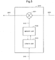
- Fig. 5 is a block diagram showing a configuration of the noise information adjustment unit 243.
- the noise information adjustment unit 243 includes a multiplication unit 501, a memory unit 502 and an update unit 503.
- the noise information adjustment unit 243 supplies supplied noise information 250 to the multiplication unit 501.
- the memory unit 502 stores a scaling factor 510 as information for modification which is used when noise information is modified.
- the multiplication unit 501 calculates a product of noise information 250 and the scaling factor 510, and outputs as modified noise information 260.
- the enhanced signal amplitude spectrum 240 is supplied to the update unit 503 as a noise suppression result.
- the update unit 503 reads the scaling factor 510 in the memory unit 502 and changes the scaling factor 510 using the noise suppression result.
- the update unit 503 supplies the new scaling factor 510 after change to the memory unit 502.
- the memory unit 502 stores the new scaling factor 510 newly instead of the old scaling factor 510 stored until then.
- the update unit 503 updates the scaling factor 510 using the noise suppression result that has been fed back to thea noise information adjustment unit 243.
- the update unit 503 updates the scaling factor 510 so that the larger a noise suppression result at timing without inputting a target signal is (the larger the residual noise without being suppressed is), the larger the modified noise information 260 becomes. That the noise suppression result at timing when the target signal is not inputted is large indicates that suppression is insufficient. Therefore, it is because it is desirable to make the modified noise information 260 large by changing the scaling factor 510.
- modified noise information 260 When modified noise information 260 is large, because a numerical value to be subtracted will be large in SS method to become large in modal SS, a noise suppression result becomes small. Also, in multiplication type suppression like MMSE STSA method, a small suppression coefficient is obtained because an estimated signal to noise ratio used for calculation of a suppression coefficient becomes small. This brings stronger noise suppression.
- a method to update a scaling factor 510 a plurality of methods can be thought. As an example, a recalculation method and a sequential update method will be described.
- the noise information adjustment unit 243 can recalculate the scaling factor or update it sequentially so that the noise may be suppressed completely. This is because, when amplitude or power of a noisy signal is small, there is a high probability that the power of signals other than the noise to be suppressed is also small.
- the noise information adjustment unit 243 can detect that the amplitude or power of a noisy signal is small using that the amplitude or power of the noisy signal is smaller than a threshold value.
- the noise information adjustment unit 243 can also detect that the amplitude or power of a noisy signal is small by a fact that a difference between the amplitude or power of a noisy signal and noise information recorded in the noise information storage unit 207 is smaller than a threshold value. That is, when the amplitude or power of the noisy signal resembles the noise information, the noise information adjustment unit 243 utilizes that the share of the noise information in the noisy signal is high (the signal to noise ratio is low). In particular, by using information at a plurality of frequency points in a combined manner, it becomes possible for the noise information adjustment unit 243 to compare spectral envelopes and make a highly accurate detection.
- the scaling factor 510 for the SS method is recalculated so that, in each frequency, modified noise information becomes equal to a noisy signal spectrum at timing when a target signal is not inputted.
- the noise information adjustment unit 243 is required that a noisy signal amplitude spectrum
- n is a frame index and k is a frequency index. That is, the scaling factor ⁇ n(k) is calculated by the following equation (8).
- ⁇ n k Yn k / ⁇ k
- ⁇ is a small constant called a step size.
- the noise information adjustment unit 243 calculates the current scaling factor ⁇ n(k) using the current error, and apply it immediately. By updating the scaling factor 510 immediately, the noise information adjustment unit 243 can realize noise suppression with high accuracy in real time.
- the noise information adjustment unit 243 calculates the scaling factor ⁇ n+1(k) by the following equation (11) using the above-mentioned error en(k).
- ⁇ n + 1 k ⁇ n k + ⁇ en k ⁇ k / ⁇ n k 2
- ⁇ n(k) 2 is the average power of the noise information vn(k), and can be calculated using an average based on an FIR filter (a moving average using a sliding window), an average based on an IIR filter (leaky integration) or the like.
- the noise information adjustment unit 243 may calculate scaling factor ⁇ n+1(k) by the following equation (13) using a signum function sgn ⁇ en (k) ⁇ which represents only the sign of the error.
- ⁇ n + 1 k ⁇ n k + ⁇ • sgn en k
- the noise information adjustment unit 243 may use the LS (Least Squares) algorithm or any other adaptation algorithm.
- the noise information adjustment unit 243 can also apply the updated scaling factor 510 immediately, or may perform real time update of the scaling factor by referring to a change from equations (9) to (10) to modify equations (11) to (13).
- the MMSE STSA method updates a scaling factor sequentially.
- the noise information adjustment unit 243 updates the scaling factor ⁇ n(k) using the same method as the method described using the equation (8) to equation (13).
- the noise information adjustment unit 243 can change an updating method such as using the sequential update method in the beginning and using the recalculation method later. In order to determine timing of changing the updating method, the noise information adjustment unit 243 may change the updating method on condition that the scaling factor became sufficiently close to the optimum value. And the noise information adjustment unit 243 may change the updating method when a predetermined time has elapsed, for example. Moreover, the noise information adjustment unit 243 may change it when a modification amount of the scaling factor has become smaller than a predetermined threshold value.
- the noise suppression apparatus 200 can compensate the difference in the performance of and the individual difference between mikes, and can perform highly-accurate noise suppression processing with little variation.
- a noise suppression apparatus 600 does not include the gain control unit 241.
- a gain calculation unit 603 in the noise suppression apparatus 600 as the third exemplary embodiment is different from the first exemplary embodiment mentioned above, and supplies the ratio of the calculated minimum value to a noise information adjustment unit 643.
- the noise information adjustment unit 643 adjusts noise information which should be supplied to the noise suppression unit 242 based on the ratio of the minimum value. At the same time, the noise information adjustment unit 643 inputs the output signal 240 outputted from the noise suppression unit 242, and adjusts so that the noise information 250 may be emphasized when there are remnants of noise.
- the noise suppression apparatus 600 is possible to adjust noise information in accordance with the difference of the performance of and the individual difference between mikes like the first exemplary embodiment, and to suppress noise, and can perform highly-accurate noise suppression with little variation.
- a noise suppression apparatus 700 as a fourth exemplary embodiment is different from the first exemplary embodiment mentioned above does not include the noise information storage unit 207, inputs a noise spectrum (noise information) in real time from a noise source via an input terminal 707 and transmits to the noise information adjustment unit 243. Because other configuration and operation are the same as the first exemplary embodiment, the detailed description will be omitted here.
- the noise information is modified based on a noise suppression result in the noise information adjustment unit 243 like the first exemplary embodiment, modified noise information is generated and the modified noise information is transmitted to the noise suppression unit 242 even in this case.
- the noise suppression apparatus 700 can obtain more accurate noise information. Because a change in noise can also be followed, the noise suppression apparatus 700 can suppress various noises including unknown noise effectively further without storing a large number of noise information in advance. In particular, because the noise information adjustment unit 243 exists, the noise suppression apparatus 700 can follow a variation in the electrical characteristic of the mike for target signals and the mike for noise.
- a fifth exemplary embodiment of the present invention will be described using Fig. 8 .
- a gain calculation unit 803, a noise suppression unit 842 and a noise information adjustment unit 843 included in a noise suppression apparatus 800 as a fourth exemplary embodiment are supplied more information (noise existence information) which shows whether specific noise exists in the inputted noisy signal from an input terminal 801.
- the noise suppression apparatus 800 can suppress the noise certainly at timing when specific noise exists and simultaneously, update information for modification.
- a noise suppression apparatus 800 can find a minimum value of the noise certainly. Because other configuration and operation are the same as the first exemplary embodiment, the detailed description will be omitted here.
- the gain calculation unit 803 may start calculation of a minimum value from t(1) after fixed time lapse from the noise start time t(0). In the case, the gain calculation unit 803 should calculate the minimum value of the noise in the sound acquired after t (2) at timing of t(2), t(3), t(4)... at stated intervals. The calculated minimum value may be stored in a ring buffer (or shift memory) as Min(2), Min(3), Min(4),..., respectively. After that, when noise end information is acquired from an input terminal 801, the gain calculation unit 803 reads the minimum values Min(n-1) to t(n-1) at the time of going back for a definite period of time from noise end time t(n).
- the gain calculation unit 803 can eliminate the minimum value of the noise in an unstable operation state such as the timing at which a motor begins to move, or just before stopping.
- the noise of a period which does not calculate a minimum value about fixed period just after noise starting and just before noise end, and only a minimum value of the noise of the stable period can be used.
- the noise suppression apparatus 800 does not update information for modification at timing when a specific noise does not exist, accuracy of noise suppression to the specific noise can be improved in addition to the effect of the second exemplary embodiment.
- a noise suppression apparatus 900 in this exemplary embodiment includes a target signal existence judgment unit 901.
- a noisy signal amplitude spectrum to which the gain was applied in the gain control unit 241 is transmitted to the target signal existence judgment unit 901.
- the target signal existence judgment unit 901 determines whether a target signal exists in the noisy signal amplitude spectrum, or how many target signals exist.
- a noise information adjustment unit 943 updates information for modification which adjusts noise information based on the judgment result by the target signal existence judgment unit 901. For example, because all noisy signals include noise when there are no target signals, the suppression result by the noise suppression unit should be zero. Accordingly, the noise information adjustment unit 943 adjusts the scaling factor 510 so that the noise suppression result at that time will be zero.
- the noise information adjustment unit 943 updates information for modification in the modification unit in accordance with the existence ratio of the target signal. For example, when the target signal exists 10% in the noisy signal, the noise information adjustment unit 943 updates information for modification partially (only 90%).
- the noise suppression apparatus 900 updates the modified information in accordance with the ratio of noise in the noisy signal in addition to the effect of the second exemplary embodiment, it can obtain a more highly-accurate noise suppression result.
- noise suppression apparatus with the respectively different feature was described in the first to the sixth exemplary embodiments mentioned above, a noise suppression apparatus of any combination of those features is also included in the category of the present invention.
- the present invention may be applied to a system including a plurality of apparatuses and it may be applied to a lone apparatus. Moreover, the present invention can be applied also when the signal processing program of the software which realizes the function of the exemplary embodiment is supplied directly or from remoteness to a system or an apparatus. Accordingly, in order to realize the function of the present invention by a computer, a medium which stored a program installed in a computer or the program and a WWW (World Wide Web) server which it makes the program download are also included in the category of the present invention.
- WWW World Wide Web
- Fig. 10 is a block diagram of a computer 1000 which executes a signal processing program when the above-mentioned exemplary embodiment is formed by the signal processing program.
- the computer 1000 includes an input unit 1001, a CPU (Central Processing Unit) 1002, an output unit 1003, a memory 1004, an external memory unit 1005 and a communication control unit 1006.
- CPU Central Processing Unit
- the CPU 1002 controls operations of the computer 1000 by reading the signal processing program. That is, the CPU 1002 that has executed the signal processing program inputs an input signal of a noisy signal through a converter device of a mike (S1011). Next, the CPU 1002 compares a minimum value of an inputted reference signal and a minimum value of the input signal through a reference converter device (S1012). And CPU 1002 modifies the input signal in accordance with the comparison result (S1013).
Applications Claiming Priority (2)
| Application Number | Priority Date | Filing Date | Title |
|---|---|---|---|
| JP2010263021 | 2010-11-25 | ||
| PCT/JP2011/077442 WO2012070684A1 (ja) | 2010-11-25 | 2011-11-22 | 信号処理装置、信号処理方法、及び信号処理プログラム |
Publications (3)
| Publication Number | Publication Date |
|---|---|
| EP2645738A1 EP2645738A1 (en) | 2013-10-02 |
| EP2645738A4 EP2645738A4 (en) | 2014-04-30 |
| EP2645738B1 true EP2645738B1 (en) | 2017-06-21 |
Family
ID=46146018
Family Applications (1)
| Application Number | Title | Priority Date | Filing Date |
|---|---|---|---|
| EP11842999.2A Active EP2645738B1 (en) | 2010-11-25 | 2011-11-22 | Signal processing device, signal processing method, and signal processing program |
Country Status (5)
| Country | Link |
|---|---|
| US (1) | US9443503B2 (ja) |
| EP (1) | EP2645738B1 (ja) |
| JP (1) | JP6182862B2 (ja) |
| CN (1) | CN103270772B (ja) |
| WO (1) | WO2012070684A1 (ja) |
Families Citing this family (3)
| Publication number | Priority date | Publication date | Assignee | Title |
|---|---|---|---|---|
| WO2017141317A1 (ja) * | 2016-02-15 | 2017-08-24 | 三菱電機株式会社 | 音響信号強調装置 |
| JP7021053B2 (ja) | 2018-11-07 | 2022-02-16 | 株式会社東芝 | 監視システム、プログラム、及び記憶媒体 |
| KR102327441B1 (ko) * | 2019-09-20 | 2021-11-17 | 엘지전자 주식회사 | 인공지능 장치 |
Family Cites Families (17)
| Publication number | Priority date | Publication date | Assignee | Title |
|---|---|---|---|---|
| JP3074952B2 (ja) | 1992-08-18 | 2000-08-07 | 日本電気株式会社 | 雑音除去装置 |
| JP3451146B2 (ja) | 1995-02-17 | 2003-09-29 | 株式会社日立製作所 | スペクトルサブトラクションを用いた雑音除去システムおよび方法 |
| US6044341A (en) | 1997-07-16 | 2000-03-28 | Olympus Optical Co., Ltd. | Noise suppression apparatus and recording medium recording processing program for performing noise removal from voice |
| JPH1138998A (ja) * | 1997-07-16 | 1999-02-12 | Olympus Optical Co Ltd | 雑音抑圧装置および雑音抑圧処理プログラムを記録した記録媒体 |
| CN1418448A (zh) * | 2000-03-14 | 2003-05-14 | 奥迪亚科技股份责任有限公司 | 多麦克风定向系统的适应性麦克风匹配 |
| JP4282227B2 (ja) | 2000-12-28 | 2009-06-17 | 日本電気株式会社 | ノイズ除去の方法及び装置 |
| JP4632047B2 (ja) * | 2003-09-02 | 2011-02-16 | 日本電気株式会社 | 信号処理方法および装置 |
| JP2005130328A (ja) * | 2003-10-27 | 2005-05-19 | Kyocera Corp | 電子カメラ |
| JP2006262241A (ja) * | 2005-03-18 | 2006-09-28 | Casio Comput Co Ltd | 電子カメラ、ノイズ低減装置及びノイズ低減制御プログラム |
| JP2006279185A (ja) | 2005-03-28 | 2006-10-12 | Casio Comput Co Ltd | 撮像装置、音声記録方法及びプログラム |
| JP4639907B2 (ja) * | 2005-03-31 | 2011-02-23 | カシオ計算機株式会社 | 撮像装置、音声記録方法及びプログラム |
| US9318119B2 (en) | 2005-09-02 | 2016-04-19 | Nec Corporation | Noise suppression using integrated frequency-domain signals |
| US7970564B2 (en) * | 2006-05-02 | 2011-06-28 | Qualcomm Incorporated | Enhancement techniques for blind source separation (BSS) |
| JP2008216721A (ja) * | 2007-03-06 | 2008-09-18 | Nec Corp | 雑音抑圧の方法、装置、及びプログラム |
| JP5236890B2 (ja) * | 2007-04-03 | 2013-07-17 | 株式会社アコー | マイクロホンユニット、騒音計及び音響校正器 |
| EP2151821B1 (en) * | 2008-08-07 | 2011-12-14 | Nuance Communications, Inc. | Noise-reduction processing of speech signals |
| JP2010263021A (ja) | 2009-04-30 | 2010-11-18 | Panasonic Corp | 偏光面検波センサー、半導体集積回路及び偏光面検波センサーの制御方法 |
-
2011
- 2011-11-22 WO PCT/JP2011/077442 patent/WO2012070684A1/ja active Application Filing
- 2011-11-22 CN CN201180056857.XA patent/CN103270772B/zh active Active
- 2011-11-22 JP JP2012545822A patent/JP6182862B2/ja active Active
- 2011-11-22 US US13/883,618 patent/US9443503B2/en active Active
- 2011-11-22 EP EP11842999.2A patent/EP2645738B1/en active Active
Also Published As
| Publication number | Publication date |
|---|---|
| CN103270772A (zh) | 2013-08-28 |
| JP6182862B2 (ja) | 2017-08-23 |
| CN103270772B (zh) | 2017-06-06 |
| WO2012070684A1 (ja) | 2012-05-31 |
| US9443503B2 (en) | 2016-09-13 |
| JPWO2012070684A1 (ja) | 2014-05-19 |
| US20130223639A1 (en) | 2013-08-29 |
| EP2645738A4 (en) | 2014-04-30 |
| EP2645738A1 (en) | 2013-10-02 |
Similar Documents
| Publication | Publication Date | Title |
|---|---|---|
| US7895038B2 (en) | Signal enhancement via noise reduction for speech recognition | |
| US9837097B2 (en) | Single processing method, information processing apparatus and signal processing program | |
| US20090192796A1 (en) | Filtering of beamformed speech signals | |
| US9105270B2 (en) | Method and apparatus for audio signal enhancement in reverberant environment | |
| US20140177853A1 (en) | Sound processing device, sound processing method, and program | |
| CN105103230B (zh) | 信号处理装置、信号处理方法、信号处理程序 | |
| EP2579255B1 (en) | Audio signal processing | |
| EP2645738B1 (en) | Signal processing device, signal processing method, and signal processing program | |
| EP2498252B1 (en) | Information processing device, auxiliary device therefor, information processing system, control method therefor, and control program | |
| JP2019020678A (ja) | ノイズ低減装置および音声認識装置 | |
| US8736359B2 (en) | Signal processing method, information processing apparatus, and storage medium for storing a signal processing program | |
| US9190070B2 (en) | Signal processing method, information processing apparatus, and storage medium for storing a signal processing program | |
| Kleinschmidt et al. | A modified LIMA framework for spectral subtraction applied to in-car speech recognition |
Legal Events
| Date | Code | Title | Description |
|---|---|---|---|
| PUAI | Public reference made under article 153(3) epc to a published international application that has entered the european phase |
Free format text: ORIGINAL CODE: 0009012 |
|
| 17P | Request for examination filed |
Effective date: 20130625 |
|
| AK | Designated contracting states |
Kind code of ref document: A1 Designated state(s): AL AT BE BG CH CY CZ DE DK EE ES FI FR GB GR HR HU IE IS IT LI LT LU LV MC MK MT NL NO PL PT RO RS SE SI SK SM TR |
|
| DAX | Request for extension of the european patent (deleted) | ||
| A4 | Supplementary search report drawn up and despatched |
Effective date: 20140401 |
|
| RIC1 | Information provided on ipc code assigned before grant |
Ipc: G10L 21/02 20130101ALI20140326BHEP Ipc: H04R 3/00 20060101AFI20140326BHEP |
|
| 17Q | First examination report despatched |
Effective date: 20151013 |
|
| GRAP | Despatch of communication of intention to grant a patent |
Free format text: ORIGINAL CODE: EPIDOSNIGR1 |
|
| GRAJ | Information related to disapproval of communication of intention to grant by the applicant or resumption of examination proceedings by the epo deleted |
Free format text: ORIGINAL CODE: EPIDOSDIGR1 |
|
| GRAP | Despatch of communication of intention to grant a patent |
Free format text: ORIGINAL CODE: EPIDOSNIGR1 |
|
| INTG | Intention to grant announced |
Effective date: 20161209 |
|
| GRAP | Despatch of communication of intention to grant a patent |
Free format text: ORIGINAL CODE: EPIDOSNIGR1 |
|
| INTG | Intention to grant announced |
Effective date: 20170109 |
|
| GRAS | Grant fee paid |
Free format text: ORIGINAL CODE: EPIDOSNIGR3 |
|
| GRAA | (expected) grant |
Free format text: ORIGINAL CODE: 0009210 |
|
| AK | Designated contracting states |
Kind code of ref document: B1 Designated state(s): AL AT BE BG CH CY CZ DE DK EE ES FI FR GB GR HR HU IE IS IT LI LT LU LV MC MK MT NL NO PL PT RO RS SE SI SK SM TR |
|
| REG | Reference to a national code |
Ref country code: GB Ref legal event code: FG4D |
|
| REG | Reference to a national code |
Ref country code: CH Ref legal event code: EP |
|
| REG | Reference to a national code |
Ref country code: IE Ref legal event code: FG4D |
|
| REG | Reference to a national code |
Ref country code: AT Ref legal event code: REF Ref document number: 903900 Country of ref document: AT Kind code of ref document: T Effective date: 20170715 |
|
| REG | Reference to a national code |
Ref country code: DE Ref legal event code: R096 Ref document number: 602011039011 Country of ref document: DE |
|
| REG | Reference to a national code |
Ref country code: FR Ref legal event code: PLFP Year of fee payment: 7 |
|
| REG | Reference to a national code |
Ref country code: NL Ref legal event code: MP Effective date: 20170621 |
|
| PG25 | Lapsed in a contracting state [announced via postgrant information from national office to epo] |
Ref country code: GR Free format text: LAPSE BECAUSE OF FAILURE TO SUBMIT A TRANSLATION OF THE DESCRIPTION OR TO PAY THE FEE WITHIN THE PRESCRIBED TIME-LIMIT Effective date: 20170922 Ref country code: FI Free format text: LAPSE BECAUSE OF FAILURE TO SUBMIT A TRANSLATION OF THE DESCRIPTION OR TO PAY THE FEE WITHIN THE PRESCRIBED TIME-LIMIT Effective date: 20170621 Ref country code: LT Free format text: LAPSE BECAUSE OF FAILURE TO SUBMIT A TRANSLATION OF THE DESCRIPTION OR TO PAY THE FEE WITHIN THE PRESCRIBED TIME-LIMIT Effective date: 20170621 Ref country code: HR Free format text: LAPSE BECAUSE OF FAILURE TO SUBMIT A TRANSLATION OF THE DESCRIPTION OR TO PAY THE FEE WITHIN THE PRESCRIBED TIME-LIMIT Effective date: 20170621 Ref country code: NO Free format text: LAPSE BECAUSE OF FAILURE TO SUBMIT A TRANSLATION OF THE DESCRIPTION OR TO PAY THE FEE WITHIN THE PRESCRIBED TIME-LIMIT Effective date: 20170921 |
|
| REG | Reference to a national code |
Ref country code: LT Ref legal event code: MG4D |
|
| REG | Reference to a national code |
Ref country code: AT Ref legal event code: MK05 Ref document number: 903900 Country of ref document: AT Kind code of ref document: T Effective date: 20170621 |
|
| PG25 | Lapsed in a contracting state [announced via postgrant information from national office to epo] |
Ref country code: SE Free format text: LAPSE BECAUSE OF FAILURE TO SUBMIT A TRANSLATION OF THE DESCRIPTION OR TO PAY THE FEE WITHIN THE PRESCRIBED TIME-LIMIT Effective date: 20170621 Ref country code: NL Free format text: LAPSE BECAUSE OF FAILURE TO SUBMIT A TRANSLATION OF THE DESCRIPTION OR TO PAY THE FEE WITHIN THE PRESCRIBED TIME-LIMIT Effective date: 20170621 Ref country code: RS Free format text: LAPSE BECAUSE OF FAILURE TO SUBMIT A TRANSLATION OF THE DESCRIPTION OR TO PAY THE FEE WITHIN THE PRESCRIBED TIME-LIMIT Effective date: 20170621 Ref country code: LV Free format text: LAPSE BECAUSE OF FAILURE TO SUBMIT A TRANSLATION OF THE DESCRIPTION OR TO PAY THE FEE WITHIN THE PRESCRIBED TIME-LIMIT Effective date: 20170621 Ref country code: BG Free format text: LAPSE BECAUSE OF FAILURE TO SUBMIT A TRANSLATION OF THE DESCRIPTION OR TO PAY THE FEE WITHIN THE PRESCRIBED TIME-LIMIT Effective date: 20170921 |
|
| PG25 | Lapsed in a contracting state [announced via postgrant information from national office to epo] |
Ref country code: AT Free format text: LAPSE BECAUSE OF FAILURE TO SUBMIT A TRANSLATION OF THE DESCRIPTION OR TO PAY THE FEE WITHIN THE PRESCRIBED TIME-LIMIT Effective date: 20170621 Ref country code: RO Free format text: LAPSE BECAUSE OF FAILURE TO SUBMIT A TRANSLATION OF THE DESCRIPTION OR TO PAY THE FEE WITHIN THE PRESCRIBED TIME-LIMIT Effective date: 20170621 Ref country code: CZ Free format text: LAPSE BECAUSE OF FAILURE TO SUBMIT A TRANSLATION OF THE DESCRIPTION OR TO PAY THE FEE WITHIN THE PRESCRIBED TIME-LIMIT Effective date: 20170621 Ref country code: EE Free format text: LAPSE BECAUSE OF FAILURE TO SUBMIT A TRANSLATION OF THE DESCRIPTION OR TO PAY THE FEE WITHIN THE PRESCRIBED TIME-LIMIT Effective date: 20170621 Ref country code: SK Free format text: LAPSE BECAUSE OF FAILURE TO SUBMIT A TRANSLATION OF THE DESCRIPTION OR TO PAY THE FEE WITHIN THE PRESCRIBED TIME-LIMIT Effective date: 20170621 |
|
| PG25 | Lapsed in a contracting state [announced via postgrant information from national office to epo] |
Ref country code: ES Free format text: LAPSE BECAUSE OF FAILURE TO SUBMIT A TRANSLATION OF THE DESCRIPTION OR TO PAY THE FEE WITHIN THE PRESCRIBED TIME-LIMIT Effective date: 20170621 Ref country code: IT Free format text: LAPSE BECAUSE OF FAILURE TO SUBMIT A TRANSLATION OF THE DESCRIPTION OR TO PAY THE FEE WITHIN THE PRESCRIBED TIME-LIMIT Effective date: 20170621 Ref country code: SM Free format text: LAPSE BECAUSE OF FAILURE TO SUBMIT A TRANSLATION OF THE DESCRIPTION OR TO PAY THE FEE WITHIN THE PRESCRIBED TIME-LIMIT Effective date: 20170621 Ref country code: IS Free format text: LAPSE BECAUSE OF FAILURE TO SUBMIT A TRANSLATION OF THE DESCRIPTION OR TO PAY THE FEE WITHIN THE PRESCRIBED TIME-LIMIT Effective date: 20171021 Ref country code: PL Free format text: LAPSE BECAUSE OF FAILURE TO SUBMIT A TRANSLATION OF THE DESCRIPTION OR TO PAY THE FEE WITHIN THE PRESCRIBED TIME-LIMIT Effective date: 20170621 |
|
| REG | Reference to a national code |
Ref country code: DE Ref legal event code: R097 Ref document number: 602011039011 Country of ref document: DE |
|
| PLBE | No opposition filed within time limit |
Free format text: ORIGINAL CODE: 0009261 |
|
| STAA | Information on the status of an ep patent application or granted ep patent |
Free format text: STATUS: NO OPPOSITION FILED WITHIN TIME LIMIT |
|
| PG25 | Lapsed in a contracting state [announced via postgrant information from national office to epo] |
Ref country code: DK Free format text: LAPSE BECAUSE OF FAILURE TO SUBMIT A TRANSLATION OF THE DESCRIPTION OR TO PAY THE FEE WITHIN THE PRESCRIBED TIME-LIMIT Effective date: 20170621 |
|
| 26N | No opposition filed |
Effective date: 20180322 |
|
| PG25 | Lapsed in a contracting state [announced via postgrant information from national office to epo] |
Ref country code: MC Free format text: LAPSE BECAUSE OF FAILURE TO SUBMIT A TRANSLATION OF THE DESCRIPTION OR TO PAY THE FEE WITHIN THE PRESCRIBED TIME-LIMIT Effective date: 20170621 |
|
| PG25 | Lapsed in a contracting state [announced via postgrant information from national office to epo] |
Ref country code: CH Free format text: LAPSE BECAUSE OF NON-PAYMENT OF DUE FEES Effective date: 20171130 Ref country code: LI Free format text: LAPSE BECAUSE OF NON-PAYMENT OF DUE FEES Effective date: 20171130 |
|
| PG25 | Lapsed in a contracting state [announced via postgrant information from national office to epo] |
Ref country code: SI Free format text: LAPSE BECAUSE OF FAILURE TO SUBMIT A TRANSLATION OF THE DESCRIPTION OR TO PAY THE FEE WITHIN THE PRESCRIBED TIME-LIMIT Effective date: 20170621 Ref country code: LU Free format text: LAPSE BECAUSE OF NON-PAYMENT OF DUE FEES Effective date: 20171122 |
|
| REG | Reference to a national code |
Ref country code: BE Ref legal event code: MM Effective date: 20171130 |
|
| REG | Reference to a national code |
Ref country code: IE Ref legal event code: MM4A |
|
| PG25 | Lapsed in a contracting state [announced via postgrant information from national office to epo] |
Ref country code: MT Free format text: LAPSE BECAUSE OF NON-PAYMENT OF DUE FEES Effective date: 20171122 |
|
| REG | Reference to a national code |
Ref country code: FR Ref legal event code: PLFP Year of fee payment: 8 |
|
| PG25 | Lapsed in a contracting state [announced via postgrant information from national office to epo] |
Ref country code: IE Free format text: LAPSE BECAUSE OF NON-PAYMENT OF DUE FEES Effective date: 20171122 |
|
| PG25 | Lapsed in a contracting state [announced via postgrant information from national office to epo] |
Ref country code: BE Free format text: LAPSE BECAUSE OF NON-PAYMENT OF DUE FEES Effective date: 20171130 |
|
| PG25 | Lapsed in a contracting state [announced via postgrant information from national office to epo] |
Ref country code: HU Free format text: LAPSE BECAUSE OF FAILURE TO SUBMIT A TRANSLATION OF THE DESCRIPTION OR TO PAY THE FEE WITHIN THE PRESCRIBED TIME-LIMIT; INVALID AB INITIO Effective date: 20111122 |
|
| PG25 | Lapsed in a contracting state [announced via postgrant information from national office to epo] |
Ref country code: CY Free format text: LAPSE BECAUSE OF NON-PAYMENT OF DUE FEES Effective date: 20170621 |
|
| PG25 | Lapsed in a contracting state [announced via postgrant information from national office to epo] |
Ref country code: MK Free format text: LAPSE BECAUSE OF FAILURE TO SUBMIT A TRANSLATION OF THE DESCRIPTION OR TO PAY THE FEE WITHIN THE PRESCRIBED TIME-LIMIT Effective date: 20170621 |
|
| PG25 | Lapsed in a contracting state [announced via postgrant information from national office to epo] |
Ref country code: TR Free format text: LAPSE BECAUSE OF FAILURE TO SUBMIT A TRANSLATION OF THE DESCRIPTION OR TO PAY THE FEE WITHIN THE PRESCRIBED TIME-LIMIT Effective date: 20170621 |
|
| PG25 | Lapsed in a contracting state [announced via postgrant information from national office to epo] |
Ref country code: PT Free format text: LAPSE BECAUSE OF FAILURE TO SUBMIT A TRANSLATION OF THE DESCRIPTION OR TO PAY THE FEE WITHIN THE PRESCRIBED TIME-LIMIT Effective date: 20170621 |
|
| PG25 | Lapsed in a contracting state [announced via postgrant information from national office to epo] |
Ref country code: AL Free format text: LAPSE BECAUSE OF FAILURE TO SUBMIT A TRANSLATION OF THE DESCRIPTION OR TO PAY THE FEE WITHIN THE PRESCRIBED TIME-LIMIT Effective date: 20170621 |
|
| PGFP | Annual fee paid to national office [announced via postgrant information from national office to epo] |
Ref country code: GB Payment date: 20231123 Year of fee payment: 13 |
|
| PGFP | Annual fee paid to national office [announced via postgrant information from national office to epo] |
Ref country code: FR Payment date: 20231120 Year of fee payment: 13 Ref country code: DE Payment date: 20231121 Year of fee payment: 13 |