EP2645529A1 - Agencement de circuit et procédé de test d'une branche de diodes lumineuses d'un agencement de circuit - Google Patents
Agencement de circuit et procédé de test d'une branche de diodes lumineuses d'un agencement de circuit Download PDFInfo
- Publication number
- EP2645529A1 EP2645529A1 EP13161845.6A EP13161845A EP2645529A1 EP 2645529 A1 EP2645529 A1 EP 2645529A1 EP 13161845 A EP13161845 A EP 13161845A EP 2645529 A1 EP2645529 A1 EP 2645529A1
- Authority
- EP
- European Patent Office
- Prior art keywords
- light
- emitting diode
- current
- branch
- diode branch
- Prior art date
- Legal status (The legal status is an assumption and is not a legal conclusion. Google has not performed a legal analysis and makes no representation as to the accuracy of the status listed.)
- Granted
Links
- 238000012360 testing method Methods 0.000 title claims abstract description 63
- 238000000034 method Methods 0.000 title claims abstract description 21
- 238000005259 measurement Methods 0.000 claims abstract description 6
- 230000007547 defect Effects 0.000 description 8
- 230000002950 deficient Effects 0.000 description 4
- 230000032683 aging Effects 0.000 description 2
- 238000013461 design Methods 0.000 description 2
- 230000000694 effects Effects 0.000 description 2
- 238000013459 approach Methods 0.000 description 1
- 238000010276 construction Methods 0.000 description 1
- 230000001419 dependent effect Effects 0.000 description 1
- 238000001514 detection method Methods 0.000 description 1
- 238000010586 diagram Methods 0.000 description 1
- 238000011990 functional testing Methods 0.000 description 1
- 238000010998 test method Methods 0.000 description 1
- 238000012795 verification Methods 0.000 description 1
Images


Classifications
-
- H—ELECTRICITY
- H05—ELECTRIC TECHNIQUES NOT OTHERWISE PROVIDED FOR
- H05B—ELECTRIC HEATING; ELECTRIC LIGHT SOURCES NOT OTHERWISE PROVIDED FOR; CIRCUIT ARRANGEMENTS FOR ELECTRIC LIGHT SOURCES, IN GENERAL
- H05B45/00—Circuit arrangements for operating light-emitting diodes [LED]
- H05B45/50—Circuit arrangements for operating light-emitting diodes [LED] responsive to malfunctions or undesirable behaviour of LEDs; responsive to LED life; Protective circuits
- H05B45/52—Circuit arrangements for operating light-emitting diodes [LED] responsive to malfunctions or undesirable behaviour of LEDs; responsive to LED life; Protective circuits in a parallel array of LEDs
-
- H—ELECTRICITY
- H05—ELECTRIC TECHNIQUES NOT OTHERWISE PROVIDED FOR
- H05B—ELECTRIC HEATING; ELECTRIC LIGHT SOURCES NOT OTHERWISE PROVIDED FOR; CIRCUIT ARRANGEMENTS FOR ELECTRIC LIGHT SOURCES, IN GENERAL
- H05B45/00—Circuit arrangements for operating light-emitting diodes [LED]
- H05B45/50—Circuit arrangements for operating light-emitting diodes [LED] responsive to malfunctions or undesirable behaviour of LEDs; responsive to LED life; Protective circuits
Definitions
- the invention relates to a circuit arrangement and a method for testing a light diode branch of a circuit arrangement, in particular emergency lighting, on functionality of its LEDs, wherein the light emitting diode branch comprises a plurality of light-emitting diodes and at least one resistor in series, in which method the light-emitting diode branch of its operating state under the influence of a constant electrical current is converted with at least a first current in a test state under impressing an electric current with a different current, wherein, taking into account at least one direct or indirect measurement of at least one electrical variable of the circuit arrangement of the LED branch is tested.
- a short circuit of one or more light-emitting diodes can disadvantageously lead to considerable currents in the circuit arrangement, whereby damage to other circuit parts is to be feared.
- the storage of standard current values for the purpose of a current comparison is relatively complex and also represents a relatively unreliable approach to fault detection - among other reasons, because currents are also due to aging phenomena the LEDs can change.
- a method for detecting a function failure of a light-emitting diode which is based on the comparison with the standard current value and does not take these circumstances into consideration, can thus fail.
- the invention achieves the stated object with regard to the method in that the light-emitting diode branch, which has at least two parallel light-emitting diodes, each with a resistor in series, a constant electric current is impressed in the test state and that in the operating and test state as electrical variable depending on a voltage at least is measured over the light-emitting diode branch, wherein the light-emitting diode branch is tested for functionality of its light-emitting diode or light-emitting diodes, taking into account the voltages measured in the operating and test states.
- the light-emitting diode branch has at least two parallel light-emitting diodes, each with a resistor in series, it may be possible for the functional state of the light-emitting diode branch to be checked reliably and reliably. If, for example, a constant electric current is impressed on the light-emitting diode branch in the test state, it is possible inter alia to prevent inadmissible high current strengths from forming in the circuit arrangement in the event of a possible short circuit of a light-emitting diode. Thus, damage to the circuitry during the test condition can be easily avoided, which can ensure a safe method of testing functionality.
- a voltage is measured at least across the light-emitting diode branch, the light-emitting diode branch being tested for functionality of its light-emitting diode or light-emitting diodes, taking into account the voltages measured in the operating and test states, in contrast to the prior art stored standard values for the purpose of a
- Verification of the functionality of the light emitting diode path or the LED branch are omitted. Namely, only the voltage levels measured in the operating and test states can be sufficient to ensure a reliable and reliable testing of preferably all LEDs of the light-emitting diode branch. With this functional test of the light-emitting diode or light-emitting diodes according to the invention, greater certainty can now be gained as to whether the light-emitting diode branch functions within the planned framework conditions or whether certain properties are present or not.
- the non-linearity of the voltage-current characteristic of a light emitting diode no longer applies, whereby the resistors contribute to increased voltage shifts.
- This can result in particular from the parallel connection of the light-emitting diodes with their series resistance.
- a comparatively simple method for checking the operation of a light-emitting diode can be provided.
- the method according to the invention is also comparatively robust.
- aging of the light-emitting diode also has only a slight effect on the method result, because even aged light-emitting diodes lead to a non-linear voltage-current characteristic and thus enable testing of the light-emitting diode or the light-emitting diodes according to the invention.
- the method by the voltage tap on the LED branch almost no dependence on the structural design, so that can result in a very versatile application or a wide range of applications.
- the method can also be used where the light-emitting diode branch has a plurality of light-emitting diodes connected in series and in parallel, each with a resistor in series.
- the light-emitting diode branch has a plurality of light-emitting diodes connected in series and in parallel, each with a resistor in series.
- a comparatively simple procedure can result if the test takes into account a ratio of the voltages measured in the operating and test states. In particular, however, the quotient of the voltage values can contribute to a meaningful result and thus to a reliable test of the light-emitting diode.
- the risk of electrical damage to the light-emitting diode branch due to overloading can be kept low in the test state. This even if there is already an electrical defect in the light-emitting diode branch.
- the invention achieves the stated object with regard to the circuit arrangement in that the light-emitting diode branch has at least two parallel light-emitting diodes each with a resistor in series, and in that the constant current source in the producible current intensity is variable with regard to its constant current, the test device for a test state of the light diode branch is connected to the constant current source for generating a constant current of a current different from the constant current and wherein the test device has a voltage measuring circuit with a Meßabgriff at least the light-emitting diode branch for measuring each voltage in its operating and test state as a measuring circuit.
- Constructive simplicity may result when using a constant current source that is variably variable in the current that can be generated with respect to its constant current to operate the light emitting diode branch in different current states, which light emitting diode branch has at least two parallel light emitting diodes each in series.
- the test device may be connected to the constant current source for generating a constant current of a different current to the constant current.
- the determination of defects in the light-emitting diode branch can be made particularly reliable if the test device has a voltage measuring circuit with a measuring tap as measuring circuit over at least the light-emitting diode branch for measuring a respective voltage in its operating and test state. Since relatively simple construction can be measured over the entire light-emitting diode branch, thus also simplify the design requirements.
- the circuit arrangement can check the operation of the light-emitting diode branch with particular certainty or can also be used there when the light-emitting diode branch has a plurality of light-emitting diodes connected in series and in parallel, each with a resistor in series.
- test device has a ratio circuit for forming a ratio of the voltages to one another in the operating and test state of the light-emitting diode branch, a comparatively high degree of constructive simplicity can be achieved in the circuit arrangement.
- the circuit arrangement can be protected against overloads in the test state in that the other current intensity of the constant current is lower than the first current intensity of the constant electrical current.
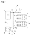
- a light-emitting diode branch 2 with six parallel LEDs (LED) 3 is shown, each of which a resistor 4 is connected in series.
- This parallel circuit 5 is connected in series with a further parallel circuit 6, which also has six parallel LEDs 3, each with a resistor 4 in series.
- the resistors 4 are used to balance the brightness of the light-emitting diodes 3, and are designed the same impedance in their impedance.
- the light-emitting diode branch 2 is supplied with a constant electric current I 1 or impressed on this light-emitting diode branch in order to supply it with electrical power.
- a constant current source 7 is used.
- the constant current intensity for generating the current I 1 can be adjusted, for example, according to the brightness requirements and this constant current intensity can certainly also be adapted to a changing brightness requirement - for example: by dimming.
- Such a setting of the desired current intensity can also be carried out by a test device 8, which measures the voltage across this resistor 9 via a resistor 9 known in the impedance and regulates the constant current source 7 with regard to the desired constant current intensity.
- This LED branch 2 is tested or checked for the functionality of its LEDs 3 by the LED branch 2 is transferred from its operating state in a test state.
- the light-emitting diode branch 2 is charged with an electric current I 2 having a current intensity which differs from the current intensity of the constant current I 1 in the operating state, which is lower here, which protects the light-emitting diode branch 2 against electrical overloading.
- a constant electric current I 2 is likewise impressed in the test state.
- the constant current source 7 is made variable in the generatable current with respect to its constant current I 1 and I 2 .
- a test device 8 switches the constant current source 7 from a constant current I 1 to a constant current I 2 in that the test device 8, which is connected to the constant current source 7 in the control network, actuates a control line 10.
- the light emitting diodes 3 are now tested for their functionality. As in of the Fig. 1 shown, these voltages U 1 and U 2 are measured at the measuring tap 11 on the light-emitting diode branch 2 in the operating and test condition.
- Fig. 2 exemplifies the effects of various defects of a circuit arrangement illustrated. If there is no defect of a light-emitting diode 3, the voltage-current characteristic 12 results. If one of the light-emitting diodes 3 is defective in that it leads to a short circuit, a voltage-current characteristic 13 can be observed. If three light-emitting diodes 3 of the light-emitting diode branch 2 are defective in that they have a line break (open), the voltage-current characteristic 14 results.
- the test device 8 has a voltage measuring circuit 15 with a measuring tap 11 on the light-emitting diode branch 2.
- the voltage measuring circuit 15 is expanded with a ratio circuit 16.
- the ratio circuit 16 stores-for example with the aid of a memory-the voltage U 1 measured in the operating state so that it can be compared with the voltage U 2 measured in the test state, for example with the aid of a comparator, which automates the test of the light-emitting diodes 2 facilitated.
- the cases 13 and 14 differ in their ratios significantly compared to the damage-free case 12.
- a flawless light-emitting branch 2 is due to the intact non-linear voltage-current characteristics of the light-emitting diodes 3, the ratio against 1.
- the significant differences can be quickly detected, analyzed and reproducible from it a test result for the functioning of the LED branch 2 are formed.
- Fig. 3 shows the general principles of the invention. A parallel circuit each of a light-emitting diode 3 in series with a resistor 4 is checked for proper functioning here.
Landscapes
- Led Devices (AREA)
Applications Claiming Priority (1)
| Application Number | Priority Date | Filing Date | Title |
|---|---|---|---|
| ATA50111/2012A AT512751B1 (de) | 2012-03-29 | 2012-03-29 | Schaltungsanordnung und Verfahren zum Testen eines Leuchtdiodenzweigs einer Schaltungsanordnung |
Publications (2)
| Publication Number | Publication Date |
|---|---|
| EP2645529A1 true EP2645529A1 (fr) | 2013-10-02 |
| EP2645529B1 EP2645529B1 (fr) | 2017-02-15 |
Family
ID=48040050
Family Applications (1)
| Application Number | Title | Priority Date | Filing Date |
|---|---|---|---|
| EP13161845.6A Active EP2645529B1 (fr) | 2012-03-29 | 2013-03-29 | Agencement de circuit et procédé de test d'une branche de diodes lumineuses d'un agencement de circuit |
Country Status (2)
| Country | Link |
|---|---|
| EP (1) | EP2645529B1 (fr) |
| AT (1) | AT512751B1 (fr) |
Cited By (2)
| Publication number | Priority date | Publication date | Assignee | Title |
|---|---|---|---|---|
| WO2014122291A1 (fr) * | 2013-02-11 | 2014-08-14 | Weidmüller Interface GmbH & Co. KG | Installation d'éclairage et procédé de détermination de l'état de fonctionnement d'une installation d'éclairage |
| RU2617148C1 (ru) * | 2016-02-01 | 2017-04-21 | Федеральное государственное бюджетное учреждение науки Научно-технологический центр микроэлектроники и субмикронных гетероструктур Российской академии наук (НТЦ микроэлектроники РАН) | Способ тестирования светодиода |
Families Citing this family (2)
| Publication number | Priority date | Publication date | Assignee | Title |
|---|---|---|---|---|
| DE102016206878A1 (de) * | 2016-04-22 | 2017-10-26 | Siemens Aktiengesellschaft | Funktionsüberwachung von LED-Lichtzeichen |
| DE102021116149A1 (de) | 2021-06-22 | 2022-12-22 | H4X E.U. | Stromversorgungsanordnung und leuchtensystem |
Citations (7)
| Publication number | Priority date | Publication date | Assignee | Title |
|---|---|---|---|---|
| EP0793402A1 (fr) * | 1996-02-28 | 1997-09-03 | Valeo Electronique | Circuit d'illumination à diodes électroluminescentes, notamment pour véhicules automobiles, feu de signalisation, et tableau de commande, l'incorporant |
| US20050242822A1 (en) * | 2004-04-30 | 2005-11-03 | Siemens Aktiengesellschaft | Method and device for testing at least one LED strip |
| EP1839928A2 (fr) * | 2006-03-29 | 2007-10-03 | KOMPLED GmbH & Co. KG | Dispositif d'éclairage pour véhicule |
| DE102006018575A1 (de) * | 2006-04-21 | 2007-10-25 | Tridonicatco Gmbh & Co. Kg | Fehlererkennung von Leuchtdioden |
| WO2008061301A1 (fr) * | 2006-11-20 | 2008-05-29 | Lednium Technology Pty Limited | Détecteur de défauts et procédé de détection de défauts pour éclairage |
| DE102009029930B3 (de) * | 2009-06-19 | 2010-11-25 | Heraeus Noblelight Gmbh | Verfahren zur Erkennung eines Ausfalls zumindest einer LED |
| DE102011078441A1 (de) * | 2010-06-30 | 2012-01-05 | Denso Corporation | Beleuchtungssteuervorrichtung mit Diagnose- und Warneigenschaft |
Family Cites Families (5)
| Publication number | Priority date | Publication date | Assignee | Title |
|---|---|---|---|---|
| JP3450001B1 (ja) * | 2002-11-21 | 2003-09-22 | 株式会社テクノローグ | Ledの劣化検査方法 |
| DE10336973B4 (de) * | 2003-08-12 | 2016-12-29 | Hella Kgaa Hueck & Co. | Verfahren zur Überwachung einer Leuchtdiode |
| US20050062481A1 (en) * | 2003-09-19 | 2005-03-24 | Thomas Vaughn | Wayside LED signal for railroad and transit applications |
| US7800876B2 (en) * | 2006-01-09 | 2010-09-21 | Microsemi Corp. - Analog Mixed Signal Group Ltd. | Fault detection mechanism for LED backlighting |
| KR101676440B1 (ko) * | 2010-01-18 | 2016-11-16 | 삼성디스플레이 주식회사 | 백라이트 유닛, 이의 구동 방법 및 이상 검출 방법 |
-
2012
- 2012-03-29 AT ATA50111/2012A patent/AT512751B1/de active
-
2013
- 2013-03-29 EP EP13161845.6A patent/EP2645529B1/fr active Active
Patent Citations (7)
| Publication number | Priority date | Publication date | Assignee | Title |
|---|---|---|---|---|
| EP0793402A1 (fr) * | 1996-02-28 | 1997-09-03 | Valeo Electronique | Circuit d'illumination à diodes électroluminescentes, notamment pour véhicules automobiles, feu de signalisation, et tableau de commande, l'incorporant |
| US20050242822A1 (en) * | 2004-04-30 | 2005-11-03 | Siemens Aktiengesellschaft | Method and device for testing at least one LED strip |
| EP1839928A2 (fr) * | 2006-03-29 | 2007-10-03 | KOMPLED GmbH & Co. KG | Dispositif d'éclairage pour véhicule |
| DE102006018575A1 (de) * | 2006-04-21 | 2007-10-25 | Tridonicatco Gmbh & Co. Kg | Fehlererkennung von Leuchtdioden |
| WO2008061301A1 (fr) * | 2006-11-20 | 2008-05-29 | Lednium Technology Pty Limited | Détecteur de défauts et procédé de détection de défauts pour éclairage |
| DE102009029930B3 (de) * | 2009-06-19 | 2010-11-25 | Heraeus Noblelight Gmbh | Verfahren zur Erkennung eines Ausfalls zumindest einer LED |
| DE102011078441A1 (de) * | 2010-06-30 | 2012-01-05 | Denso Corporation | Beleuchtungssteuervorrichtung mit Diagnose- und Warneigenschaft |
Cited By (2)
| Publication number | Priority date | Publication date | Assignee | Title |
|---|---|---|---|---|
| WO2014122291A1 (fr) * | 2013-02-11 | 2014-08-14 | Weidmüller Interface GmbH & Co. KG | Installation d'éclairage et procédé de détermination de l'état de fonctionnement d'une installation d'éclairage |
| RU2617148C1 (ru) * | 2016-02-01 | 2017-04-21 | Федеральное государственное бюджетное учреждение науки Научно-технологический центр микроэлектроники и субмикронных гетероструктур Российской академии наук (НТЦ микроэлектроники РАН) | Способ тестирования светодиода |
Also Published As
| Publication number | Publication date |
|---|---|
| EP2645529B1 (fr) | 2017-02-15 |
| AT512751B1 (de) | 2015-03-15 |
| AT512751A1 (de) | 2013-10-15 |
Similar Documents
| Publication | Publication Date | Title |
|---|---|---|
| DE102010002707B4 (de) | Fehlererkennung für eine Serienschaltung von Leuchtdioden | |
| DE112014002911B4 (de) | LED-Treiber mit umfassendem Fehlerschutz | |
| DE102012107766B4 (de) | Fehlererkennung für eine Serienschaltung elektrischer Lasten | |
| EP2645529B1 (fr) | Agencement de circuit et procédé de test d'une branche de diodes lumineuses d'un agencement de circuit | |
| DE102015008110B4 (de) | Verfahren zur Überwachung mindestens zweier unterschiedlich langer LED-Ketten | |
| EP3631976B1 (fr) | Procédé servant à identifier un contact défectueux dans une installation photovoltaïque | |
| DE102015116943A1 (de) | Detektion eines einzelnen LED-Fehlers in einer LED-Kette | |
| WO2017136864A1 (fr) | Procédé et dispositif ict de contrôle de modules d'un dispositif d'éclairage qui contiennent au moins deux led | |
| DE102013013950A1 (de) | Verfahren, Messanordnung und Messgerät zur Bestimmung von lsolationswiderständen von Einzelzellen einer Hochvoltbatterie | |
| DE202010016782U1 (de) | Spannungsanzeigevorrichtung | |
| DE102020132666B3 (de) | Vorrichtung und Verfahren zur sicherheitsrelevanten Erfassung des Spannungsabfalls über ein Leuchtmittel in einem Fahrzeug | |
| EP2866526A1 (fr) | Circuit à DEL et procédé de fonctionnement d'un circuit à DEL | |
| DE1538609C3 (de) | Transistorisierte Schaltungsanordnung zum automatischen Prüfen gedruckter Leitungszüge | |
| DE102013219490A1 (de) | Verfahren und Vorrichtung zum Lokalisieren eines Lichtbogens in einem Strompfad einer Fotovoltaikanlage | |
| DE112007000397T5 (de) | Messvorrichtung und Messverfahren | |
| DE102013107699A1 (de) | Spannungsbegrenzer | |
| DE102011105550B4 (de) | Treiberanordnung, Beleuchtungsanordnung und Verfahren zur Detektion eines Fehlerzustandes einer Leuchteinheit | |
| WO2019091824A1 (fr) | Système d'accumulateur à batterie | |
| EP1986935B1 (fr) | Dispositif de contrôle d'une platine électrotechnique avec une piste conductrice | |
| DE102012004944B4 (de) | Verfahren zum Überprüfen der Funktion von elektrischen Anschlüssen eines analogen oder digitalen Schaltkreises | |
| DE102020008118A1 (de) | Verfahren zur sicherheitsrelevanten Erfassung des Spannungsabfalls über ein Leuchtmittel in einem Fahrzeug | |
| DE102013223478A1 (de) | Vorrichtung zum Ansteuern einer Last | |
| DE102015017315B3 (de) | Verfahren zur Überwachung mindestens zweier LED-Ketten mit LEDs unterschiedlicher Flussspannungen | |
| WO2015192911A1 (fr) | Procédé de détermination du nombre d'étages de semi-conducteurs intacts | |
| DE102014207348A1 (de) | Elektrische schaltung |
Legal Events
| Date | Code | Title | Description |
|---|---|---|---|
| PUAI | Public reference made under article 153(3) epc to a published international application that has entered the european phase |
Free format text: ORIGINAL CODE: 0009012 |
|
| AK | Designated contracting states |
Kind code of ref document: A1 Designated state(s): AL AT BE BG CH CY CZ DE DK EE ES FI FR GB GR HR HU IE IS IT LI LT LU LV MC MK MT NL NO PL PT RO RS SE SI SK SM TR |
|
| AX | Request for extension of the european patent |
Extension state: BA ME |
|
| 17P | Request for examination filed |
Effective date: 20140402 |
|
| RBV | Designated contracting states (corrected) |
Designated state(s): AL AT BE BG CH CY CZ DE DK EE ES FI FR GB GR HR HU IE IS IT LI LT LU LV MC MK MT NL NO PL PT RO RS SE SI SK SM TR |
|
| GRAP | Despatch of communication of intention to grant a patent |
Free format text: ORIGINAL CODE: EPIDOSNIGR1 |
|
| INTG | Intention to grant announced |
Effective date: 20160324 |
|
| GRAS | Grant fee paid |
Free format text: ORIGINAL CODE: EPIDOSNIGR3 |
|
| GRAJ | Information related to disapproval of communication of intention to grant by the applicant or resumption of examination proceedings by the epo deleted |
Free format text: ORIGINAL CODE: EPIDOSDIGR1 |
|
| GRAL | Information related to payment of fee for publishing/printing deleted |
Free format text: ORIGINAL CODE: EPIDOSDIGR3 |
|
| GRAP | Despatch of communication of intention to grant a patent |
Free format text: ORIGINAL CODE: EPIDOSNIGR1 |
|
| INTC | Intention to grant announced (deleted) | ||
| INTG | Intention to grant announced |
Effective date: 20160824 |
|
| GRAA | (expected) grant |
Free format text: ORIGINAL CODE: 0009210 |
|
| AK | Designated contracting states |
Kind code of ref document: B1 Designated state(s): AL AT BE BG CH CY CZ DE DK EE ES FI FR GB GR HR HU IE IS IT LI LT LU LV MC MK MT NL NO PL PT RO RS SE SI SK SM TR |
|
| REG | Reference to a national code |
Ref country code: CH Ref legal event code: EP Ref country code: GB Ref legal event code: FG4D Free format text: NOT ENGLISH |
|
| REG | Reference to a national code |
Ref country code: IE Ref legal event code: FG4D Free format text: LANGUAGE OF EP DOCUMENT: GERMAN |
|
| REG | Reference to a national code |
Ref country code: AT Ref legal event code: REF Ref document number: 868391 Country of ref document: AT Kind code of ref document: T Effective date: 20170315 |
|
| REG | Reference to a national code |
Ref country code: DE Ref legal event code: R096 Ref document number: 502013006354 Country of ref document: DE |
|
| REG | Reference to a national code |
Ref country code: NL Ref legal event code: MP Effective date: 20170215 |
|
| REG | Reference to a national code |
Ref country code: LT Ref legal event code: MG4D |
|
| PG25 | Lapsed in a contracting state [announced via postgrant information from national office to epo] |
Ref country code: LT Free format text: LAPSE BECAUSE OF FAILURE TO SUBMIT A TRANSLATION OF THE DESCRIPTION OR TO PAY THE FEE WITHIN THE PRESCRIBED TIME-LIMIT Effective date: 20170215 Ref country code: HR Free format text: LAPSE BECAUSE OF FAILURE TO SUBMIT A TRANSLATION OF THE DESCRIPTION OR TO PAY THE FEE WITHIN THE PRESCRIBED TIME-LIMIT Effective date: 20170215 Ref country code: NO Free format text: LAPSE BECAUSE OF FAILURE TO SUBMIT A TRANSLATION OF THE DESCRIPTION OR TO PAY THE FEE WITHIN THE PRESCRIBED TIME-LIMIT Effective date: 20170515 Ref country code: FI Free format text: LAPSE BECAUSE OF FAILURE TO SUBMIT A TRANSLATION OF THE DESCRIPTION OR TO PAY THE FEE WITHIN THE PRESCRIBED TIME-LIMIT Effective date: 20170215 |
|
| PG25 | Lapsed in a contracting state [announced via postgrant information from national office to epo] |
Ref country code: SE Free format text: LAPSE BECAUSE OF FAILURE TO SUBMIT A TRANSLATION OF THE DESCRIPTION OR TO PAY THE FEE WITHIN THE PRESCRIBED TIME-LIMIT Effective date: 20170215 Ref country code: PT Free format text: LAPSE BECAUSE OF FAILURE TO SUBMIT A TRANSLATION OF THE DESCRIPTION OR TO PAY THE FEE WITHIN THE PRESCRIBED TIME-LIMIT Effective date: 20170615 Ref country code: NL Free format text: LAPSE BECAUSE OF FAILURE TO SUBMIT A TRANSLATION OF THE DESCRIPTION OR TO PAY THE FEE WITHIN THE PRESCRIBED TIME-LIMIT Effective date: 20170215 Ref country code: ES Free format text: LAPSE BECAUSE OF FAILURE TO SUBMIT A TRANSLATION OF THE DESCRIPTION OR TO PAY THE FEE WITHIN THE PRESCRIBED TIME-LIMIT Effective date: 20170215 Ref country code: LV Free format text: LAPSE BECAUSE OF FAILURE TO SUBMIT A TRANSLATION OF THE DESCRIPTION OR TO PAY THE FEE WITHIN THE PRESCRIBED TIME-LIMIT Effective date: 20170215 Ref country code: RS Free format text: LAPSE BECAUSE OF FAILURE TO SUBMIT A TRANSLATION OF THE DESCRIPTION OR TO PAY THE FEE WITHIN THE PRESCRIBED TIME-LIMIT Effective date: 20170215 Ref country code: BG Free format text: LAPSE BECAUSE OF FAILURE TO SUBMIT A TRANSLATION OF THE DESCRIPTION OR TO PAY THE FEE WITHIN THE PRESCRIBED TIME-LIMIT Effective date: 20170515 |
|
| PG25 | Lapsed in a contracting state [announced via postgrant information from national office to epo] |
Ref country code: SK Free format text: LAPSE BECAUSE OF FAILURE TO SUBMIT A TRANSLATION OF THE DESCRIPTION OR TO PAY THE FEE WITHIN THE PRESCRIBED TIME-LIMIT Effective date: 20170215 Ref country code: CZ Free format text: LAPSE BECAUSE OF FAILURE TO SUBMIT A TRANSLATION OF THE DESCRIPTION OR TO PAY THE FEE WITHIN THE PRESCRIBED TIME-LIMIT Effective date: 20170215 Ref country code: RO Free format text: LAPSE BECAUSE OF FAILURE TO SUBMIT A TRANSLATION OF THE DESCRIPTION OR TO PAY THE FEE WITHIN THE PRESCRIBED TIME-LIMIT Effective date: 20170215 Ref country code: EE Free format text: LAPSE BECAUSE OF FAILURE TO SUBMIT A TRANSLATION OF THE DESCRIPTION OR TO PAY THE FEE WITHIN THE PRESCRIBED TIME-LIMIT Effective date: 20170215 Ref country code: IT Free format text: LAPSE BECAUSE OF FAILURE TO SUBMIT A TRANSLATION OF THE DESCRIPTION OR TO PAY THE FEE WITHIN THE PRESCRIBED TIME-LIMIT Effective date: 20170215 |
|
| REG | Reference to a national code |
Ref country code: CH Ref legal event code: PL |
|
| REG | Reference to a national code |
Ref country code: DE Ref legal event code: R097 Ref document number: 502013006354 Country of ref document: DE |
|
| PG25 | Lapsed in a contracting state [announced via postgrant information from national office to epo] |
Ref country code: MC Free format text: LAPSE BECAUSE OF FAILURE TO SUBMIT A TRANSLATION OF THE DESCRIPTION OR TO PAY THE FEE WITHIN THE PRESCRIBED TIME-LIMIT Effective date: 20170215 Ref country code: DK Free format text: LAPSE BECAUSE OF FAILURE TO SUBMIT A TRANSLATION OF THE DESCRIPTION OR TO PAY THE FEE WITHIN THE PRESCRIBED TIME-LIMIT Effective date: 20170215 Ref country code: SM Free format text: LAPSE BECAUSE OF FAILURE TO SUBMIT A TRANSLATION OF THE DESCRIPTION OR TO PAY THE FEE WITHIN THE PRESCRIBED TIME-LIMIT Effective date: 20170215 Ref country code: PL Free format text: LAPSE BECAUSE OF FAILURE TO SUBMIT A TRANSLATION OF THE DESCRIPTION OR TO PAY THE FEE WITHIN THE PRESCRIBED TIME-LIMIT Effective date: 20170215 |
|
| PLBE | No opposition filed within time limit |
Free format text: ORIGINAL CODE: 0009261 |
|
| STAA | Information on the status of an ep patent application or granted ep patent |
Free format text: STATUS: NO OPPOSITION FILED WITHIN TIME LIMIT |
|
| REG | Reference to a national code |
Ref country code: IE Ref legal event code: MM4A |
|
| REG | Reference to a national code |
Ref country code: FR Ref legal event code: ST Effective date: 20171130 |
|
| 26N | No opposition filed |
Effective date: 20171116 |
|
| GBPC | Gb: european patent ceased through non-payment of renewal fee |
Effective date: 20170515 |
|
| PG25 | Lapsed in a contracting state [announced via postgrant information from national office to epo] |
Ref country code: LU Free format text: LAPSE BECAUSE OF NON-PAYMENT OF DUE FEES Effective date: 20170329 Ref country code: FR Free format text: LAPSE BECAUSE OF NON-PAYMENT OF DUE FEES Effective date: 20170418 |
|
| PG25 | Lapsed in a contracting state [announced via postgrant information from national office to epo] |
Ref country code: SI Free format text: LAPSE BECAUSE OF FAILURE TO SUBMIT A TRANSLATION OF THE DESCRIPTION OR TO PAY THE FEE WITHIN THE PRESCRIBED TIME-LIMIT Effective date: 20170215 Ref country code: LI Free format text: LAPSE BECAUSE OF NON-PAYMENT OF DUE FEES Effective date: 20170331 Ref country code: CH Free format text: LAPSE BECAUSE OF NON-PAYMENT OF DUE FEES Effective date: 20170331 Ref country code: IE Free format text: LAPSE BECAUSE OF NON-PAYMENT OF DUE FEES Effective date: 20170329 |
|
| REG | Reference to a national code |
Ref country code: BE Ref legal event code: MM Effective date: 20170331 |
|
| PG25 | Lapsed in a contracting state [announced via postgrant information from national office to epo] |
Ref country code: GB Free format text: LAPSE BECAUSE OF NON-PAYMENT OF DUE FEES Effective date: 20170515 |
|
| PG25 | Lapsed in a contracting state [announced via postgrant information from national office to epo] |
Ref country code: BE Free format text: LAPSE BECAUSE OF NON-PAYMENT OF DUE FEES Effective date: 20170331 |
|
| PG25 | Lapsed in a contracting state [announced via postgrant information from national office to epo] |
Ref country code: MT Free format text: LAPSE BECAUSE OF FAILURE TO SUBMIT A TRANSLATION OF THE DESCRIPTION OR TO PAY THE FEE WITHIN THE PRESCRIBED TIME-LIMIT Effective date: 20170215 |
|
| PG25 | Lapsed in a contracting state [announced via postgrant information from national office to epo] |
Ref country code: HU Free format text: LAPSE BECAUSE OF FAILURE TO SUBMIT A TRANSLATION OF THE DESCRIPTION OR TO PAY THE FEE WITHIN THE PRESCRIBED TIME-LIMIT; INVALID AB INITIO Effective date: 20130329 |
|
| PG25 | Lapsed in a contracting state [announced via postgrant information from national office to epo] |
Ref country code: CY Free format text: LAPSE BECAUSE OF NON-PAYMENT OF DUE FEES Effective date: 20170215 |
|
| PG25 | Lapsed in a contracting state [announced via postgrant information from national office to epo] |
Ref country code: MK Free format text: LAPSE BECAUSE OF FAILURE TO SUBMIT A TRANSLATION OF THE DESCRIPTION OR TO PAY THE FEE WITHIN THE PRESCRIBED TIME-LIMIT Effective date: 20170215 |
|
| PG25 | Lapsed in a contracting state [announced via postgrant information from national office to epo] |
Ref country code: TR Free format text: LAPSE BECAUSE OF FAILURE TO SUBMIT A TRANSLATION OF THE DESCRIPTION OR TO PAY THE FEE WITHIN THE PRESCRIBED TIME-LIMIT Effective date: 20170215 |
|
| PG25 | Lapsed in a contracting state [announced via postgrant information from national office to epo] |
Ref country code: GR Free format text: LAPSE BECAUSE OF FAILURE TO SUBMIT A TRANSLATION OF THE DESCRIPTION OR TO PAY THE FEE WITHIN THE PRESCRIBED TIME-LIMIT Effective date: 20170215 |
|
| PG25 | Lapsed in a contracting state [announced via postgrant information from national office to epo] |
Ref country code: AL Free format text: LAPSE BECAUSE OF FAILURE TO SUBMIT A TRANSLATION OF THE DESCRIPTION OR TO PAY THE FEE WITHIN THE PRESCRIBED TIME-LIMIT Effective date: 20170215 Ref country code: IS Free format text: LAPSE BECAUSE OF FAILURE TO SUBMIT A TRANSLATION OF THE DESCRIPTION OR TO PAY THE FEE WITHIN THE PRESCRIBED TIME-LIMIT Effective date: 20170615 |
|
| P01 | Opt-out of the competence of the unified patent court (upc) registered |
Effective date: 20230514 |
|
| REG | Reference to a national code |
Ref country code: DE Ref legal event code: R081 Ref document number: 502013006354 Country of ref document: DE Owner name: DIN - DIETMAR NOCKER FACILITYMANAGEMENT GMBH &, AT Free format text: FORMER OWNER: DIN - DIETMAR NOCKER FACILITYMANAGEMENT GMBH, LINZ, AT |
|
| REG | Reference to a national code |
Ref country code: AT Ref legal event code: PC Ref document number: 868391 Country of ref document: AT Kind code of ref document: T Owner name: DIN-DIETMAR NOCKER FACILITYMANAGEMENT GMBH & C, AT Effective date: 20240122 |
|
| PGFP | Annual fee paid to national office [announced via postgrant information from national office to epo] |
Ref country code: AT Payment date: 20240318 Year of fee payment: 12 |
|
| PGFP | Annual fee paid to national office [announced via postgrant information from national office to epo] |
Ref country code: DE Payment date: 20240321 Year of fee payment: 12 |