EP2645527A1 - Bloc-batteries - Google Patents
Bloc-batteries Download PDFInfo
- Publication number
- EP2645527A1 EP2645527A1 EP13153760.7A EP13153760A EP2645527A1 EP 2645527 A1 EP2645527 A1 EP 2645527A1 EP 13153760 A EP13153760 A EP 13153760A EP 2645527 A1 EP2645527 A1 EP 2645527A1
- Authority
- EP
- European Patent Office
- Prior art keywords
- battery
- charging
- limit
- discharging
- module
- Prior art date
- Legal status (The legal status is an assumption and is not a legal conclusion. Google has not performed a legal analysis and makes no representation as to the accuracy of the status listed.)
- Withdrawn
Links
Images


Classifications
-
- H—ELECTRICITY
- H01—ELECTRIC ELEMENTS
- H01M—PROCESSES OR MEANS, e.g. BATTERIES, FOR THE DIRECT CONVERSION OF CHEMICAL ENERGY INTO ELECTRICAL ENERGY
- H01M50/00—Constructional details or processes of manufacture of the non-active parts of electrochemical cells other than fuel cells, e.g. hybrid cells
- H01M50/50—Current conducting connections for cells or batteries
- H01M50/572—Means for preventing undesired use or discharge
-
- B—PERFORMING OPERATIONS; TRANSPORTING
- B60—VEHICLES IN GENERAL
- B60L—PROPULSION OF ELECTRICALLY-PROPELLED VEHICLES; SUPPLYING ELECTRIC POWER FOR AUXILIARY EQUIPMENT OF ELECTRICALLY-PROPELLED VEHICLES; ELECTRODYNAMIC BRAKE SYSTEMS FOR VEHICLES IN GENERAL; MAGNETIC SUSPENSION OR LEVITATION FOR VEHICLES; MONITORING OPERATING VARIABLES OF ELECTRICALLY-PROPELLED VEHICLES; ELECTRIC SAFETY DEVICES FOR ELECTRICALLY-PROPELLED VEHICLES
- B60L3/00—Electric devices on electrically-propelled vehicles for safety purposes; Monitoring operating variables, e.g. speed, deceleration or energy consumption
- B60L3/0023—Detecting, eliminating, remedying or compensating for drive train abnormalities, e.g. failures within the drive train
- B60L3/0046—Detecting, eliminating, remedying or compensating for drive train abnormalities, e.g. failures within the drive train relating to electric energy storage systems, e.g. batteries or capacitors
-
- B—PERFORMING OPERATIONS; TRANSPORTING
- B60—VEHICLES IN GENERAL
- B60L—PROPULSION OF ELECTRICALLY-PROPELLED VEHICLES; SUPPLYING ELECTRIC POWER FOR AUXILIARY EQUIPMENT OF ELECTRICALLY-PROPELLED VEHICLES; ELECTRODYNAMIC BRAKE SYSTEMS FOR VEHICLES IN GENERAL; MAGNETIC SUSPENSION OR LEVITATION FOR VEHICLES; MONITORING OPERATING VARIABLES OF ELECTRICALLY-PROPELLED VEHICLES; ELECTRIC SAFETY DEVICES FOR ELECTRICALLY-PROPELLED VEHICLES
- B60L3/00—Electric devices on electrically-propelled vehicles for safety purposes; Monitoring operating variables, e.g. speed, deceleration or energy consumption
- B60L3/0092—Electric devices on electrically-propelled vehicles for safety purposes; Monitoring operating variables, e.g. speed, deceleration or energy consumption with use of redundant elements for safety purposes
-
- B—PERFORMING OPERATIONS; TRANSPORTING
- B60—VEHICLES IN GENERAL
- B60L—PROPULSION OF ELECTRICALLY-PROPELLED VEHICLES; SUPPLYING ELECTRIC POWER FOR AUXILIARY EQUIPMENT OF ELECTRICALLY-PROPELLED VEHICLES; ELECTRODYNAMIC BRAKE SYSTEMS FOR VEHICLES IN GENERAL; MAGNETIC SUSPENSION OR LEVITATION FOR VEHICLES; MONITORING OPERATING VARIABLES OF ELECTRICALLY-PROPELLED VEHICLES; ELECTRIC SAFETY DEVICES FOR ELECTRICALLY-PROPELLED VEHICLES
- B60L3/00—Electric devices on electrically-propelled vehicles for safety purposes; Monitoring operating variables, e.g. speed, deceleration or energy consumption
- B60L3/04—Cutting off the power supply under fault conditions
-
- B—PERFORMING OPERATIONS; TRANSPORTING
- B60—VEHICLES IN GENERAL
- B60L—PROPULSION OF ELECTRICALLY-PROPELLED VEHICLES; SUPPLYING ELECTRIC POWER FOR AUXILIARY EQUIPMENT OF ELECTRICALLY-PROPELLED VEHICLES; ELECTRODYNAMIC BRAKE SYSTEMS FOR VEHICLES IN GENERAL; MAGNETIC SUSPENSION OR LEVITATION FOR VEHICLES; MONITORING OPERATING VARIABLES OF ELECTRICALLY-PROPELLED VEHICLES; ELECTRIC SAFETY DEVICES FOR ELECTRICALLY-PROPELLED VEHICLES
- B60L58/00—Methods or circuit arrangements for monitoring or controlling batteries or fuel cells, specially adapted for electric vehicles
- B60L58/10—Methods or circuit arrangements for monitoring or controlling batteries or fuel cells, specially adapted for electric vehicles for monitoring or controlling batteries
- B60L58/12—Methods or circuit arrangements for monitoring or controlling batteries or fuel cells, specially adapted for electric vehicles for monitoring or controlling batteries responding to state of charge [SoC]
- B60L58/13—Maintaining the SoC within a determined range
-
- B—PERFORMING OPERATIONS; TRANSPORTING
- B60—VEHICLES IN GENERAL
- B60L—PROPULSION OF ELECTRICALLY-PROPELLED VEHICLES; SUPPLYING ELECTRIC POWER FOR AUXILIARY EQUIPMENT OF ELECTRICALLY-PROPELLED VEHICLES; ELECTRODYNAMIC BRAKE SYSTEMS FOR VEHICLES IN GENERAL; MAGNETIC SUSPENSION OR LEVITATION FOR VEHICLES; MONITORING OPERATING VARIABLES OF ELECTRICALLY-PROPELLED VEHICLES; ELECTRIC SAFETY DEVICES FOR ELECTRICALLY-PROPELLED VEHICLES
- B60L58/00—Methods or circuit arrangements for monitoring or controlling batteries or fuel cells, specially adapted for electric vehicles
- B60L58/10—Methods or circuit arrangements for monitoring or controlling batteries or fuel cells, specially adapted for electric vehicles for monitoring or controlling batteries
- B60L58/12—Methods or circuit arrangements for monitoring or controlling batteries or fuel cells, specially adapted for electric vehicles for monitoring or controlling batteries responding to state of charge [SoC]
- B60L58/14—Preventing excessive discharging
-
- B—PERFORMING OPERATIONS; TRANSPORTING
- B60—VEHICLES IN GENERAL
- B60L—PROPULSION OF ELECTRICALLY-PROPELLED VEHICLES; SUPPLYING ELECTRIC POWER FOR AUXILIARY EQUIPMENT OF ELECTRICALLY-PROPELLED VEHICLES; ELECTRODYNAMIC BRAKE SYSTEMS FOR VEHICLES IN GENERAL; MAGNETIC SUSPENSION OR LEVITATION FOR VEHICLES; MONITORING OPERATING VARIABLES OF ELECTRICALLY-PROPELLED VEHICLES; ELECTRIC SAFETY DEVICES FOR ELECTRICALLY-PROPELLED VEHICLES
- B60L58/00—Methods or circuit arrangements for monitoring or controlling batteries or fuel cells, specially adapted for electric vehicles
- B60L58/10—Methods or circuit arrangements for monitoring or controlling batteries or fuel cells, specially adapted for electric vehicles for monitoring or controlling batteries
- B60L58/12—Methods or circuit arrangements for monitoring or controlling batteries or fuel cells, specially adapted for electric vehicles for monitoring or controlling batteries responding to state of charge [SoC]
- B60L58/15—Preventing overcharging
-
- B—PERFORMING OPERATIONS; TRANSPORTING
- B60—VEHICLES IN GENERAL
- B60L—PROPULSION OF ELECTRICALLY-PROPELLED VEHICLES; SUPPLYING ELECTRIC POWER FOR AUXILIARY EQUIPMENT OF ELECTRICALLY-PROPELLED VEHICLES; ELECTRODYNAMIC BRAKE SYSTEMS FOR VEHICLES IN GENERAL; MAGNETIC SUSPENSION OR LEVITATION FOR VEHICLES; MONITORING OPERATING VARIABLES OF ELECTRICALLY-PROPELLED VEHICLES; ELECTRIC SAFETY DEVICES FOR ELECTRICALLY-PROPELLED VEHICLES
- B60L58/00—Methods or circuit arrangements for monitoring or controlling batteries or fuel cells, specially adapted for electric vehicles
- B60L58/10—Methods or circuit arrangements for monitoring or controlling batteries or fuel cells, specially adapted for electric vehicles for monitoring or controlling batteries
- B60L58/18—Methods or circuit arrangements for monitoring or controlling batteries or fuel cells, specially adapted for electric vehicles for monitoring or controlling batteries of two or more battery modules
- B60L58/20—Methods or circuit arrangements for monitoring or controlling batteries or fuel cells, specially adapted for electric vehicles for monitoring or controlling batteries of two or more battery modules having different nominal voltages
-
- B—PERFORMING OPERATIONS; TRANSPORTING
- B60—VEHICLES IN GENERAL
- B60L—PROPULSION OF ELECTRICALLY-PROPELLED VEHICLES; SUPPLYING ELECTRIC POWER FOR AUXILIARY EQUIPMENT OF ELECTRICALLY-PROPELLED VEHICLES; ELECTRODYNAMIC BRAKE SYSTEMS FOR VEHICLES IN GENERAL; MAGNETIC SUSPENSION OR LEVITATION FOR VEHICLES; MONITORING OPERATING VARIABLES OF ELECTRICALLY-PROPELLED VEHICLES; ELECTRIC SAFETY DEVICES FOR ELECTRICALLY-PROPELLED VEHICLES
- B60L58/00—Methods or circuit arrangements for monitoring or controlling batteries or fuel cells, specially adapted for electric vehicles
- B60L58/10—Methods or circuit arrangements for monitoring or controlling batteries or fuel cells, specially adapted for electric vehicles for monitoring or controlling batteries
- B60L58/18—Methods or circuit arrangements for monitoring or controlling batteries or fuel cells, specially adapted for electric vehicles for monitoring or controlling batteries of two or more battery modules
- B60L58/22—Balancing the charge of battery modules
-
- B—PERFORMING OPERATIONS; TRANSPORTING
- B60—VEHICLES IN GENERAL
- B60L—PROPULSION OF ELECTRICALLY-PROPELLED VEHICLES; SUPPLYING ELECTRIC POWER FOR AUXILIARY EQUIPMENT OF ELECTRICALLY-PROPELLED VEHICLES; ELECTRODYNAMIC BRAKE SYSTEMS FOR VEHICLES IN GENERAL; MAGNETIC SUSPENSION OR LEVITATION FOR VEHICLES; MONITORING OPERATING VARIABLES OF ELECTRICALLY-PROPELLED VEHICLES; ELECTRIC SAFETY DEVICES FOR ELECTRICALLY-PROPELLED VEHICLES
- B60L58/00—Methods or circuit arrangements for monitoring or controlling batteries or fuel cells, specially adapted for electric vehicles
- B60L58/10—Methods or circuit arrangements for monitoring or controlling batteries or fuel cells, specially adapted for electric vehicles for monitoring or controlling batteries
- B60L58/24—Methods or circuit arrangements for monitoring or controlling batteries or fuel cells, specially adapted for electric vehicles for monitoring or controlling batteries for controlling the temperature of batteries
- B60L58/25—Methods or circuit arrangements for monitoring or controlling batteries or fuel cells, specially adapted for electric vehicles for monitoring or controlling batteries for controlling the temperature of batteries by controlling the electric load
-
- H—ELECTRICITY
- H02—GENERATION; CONVERSION OR DISTRIBUTION OF ELECTRIC POWER
- H02J—CIRCUIT ARRANGEMENTS OR SYSTEMS FOR SUPPLYING OR DISTRIBUTING ELECTRIC POWER; SYSTEMS FOR STORING ELECTRIC ENERGY
- H02J7/00—Circuit arrangements for charging or depolarising batteries or for supplying loads from batteries
- H02J7/0029—Circuit arrangements for charging or depolarising batteries or for supplying loads from batteries with safety or protection devices or circuits
- H02J7/0031—Circuit arrangements for charging or depolarising batteries or for supplying loads from batteries with safety or protection devices or circuits using battery or load disconnect circuits
-
- H—ELECTRICITY
- H02—GENERATION; CONVERSION OR DISTRIBUTION OF ELECTRIC POWER
- H02J—CIRCUIT ARRANGEMENTS OR SYSTEMS FOR SUPPLYING OR DISTRIBUTING ELECTRIC POWER; SYSTEMS FOR STORING ELECTRIC ENERGY
- H02J7/00—Circuit arrangements for charging or depolarising batteries or for supplying loads from batteries
- H02J7/007—Regulation of charging or discharging current or voltage
- H02J7/00712—Regulation of charging or discharging current or voltage the cycle being controlled or terminated in response to electric parameters
- H02J7/00714—Regulation of charging or discharging current or voltage the cycle being controlled or terminated in response to electric parameters in response to battery charging or discharging current
- H02J7/00716—Regulation of charging or discharging current or voltage the cycle being controlled or terminated in response to electric parameters in response to battery charging or discharging current in response to integrated charge or discharge current
-
- H—ELECTRICITY
- H02—GENERATION; CONVERSION OR DISTRIBUTION OF ELECTRIC POWER
- H02J—CIRCUIT ARRANGEMENTS OR SYSTEMS FOR SUPPLYING OR DISTRIBUTING ELECTRIC POWER; SYSTEMS FOR STORING ELECTRIC ENERGY
- H02J7/00—Circuit arrangements for charging or depolarising batteries or for supplying loads from batteries
- H02J7/007—Regulation of charging or discharging current or voltage
- H02J7/007188—Regulation of charging or discharging current or voltage the charge cycle being controlled or terminated in response to non-electric parameters
- H02J7/00719—Regulation of charging or discharging current or voltage the charge cycle being controlled or terminated in response to non-electric parameters in response to degree of gas development in the battery
-
- H—ELECTRICITY
- H02—GENERATION; CONVERSION OR DISTRIBUTION OF ELECTRIC POWER
- H02J—CIRCUIT ARRANGEMENTS OR SYSTEMS FOR SUPPLYING OR DISTRIBUTING ELECTRIC POWER; SYSTEMS FOR STORING ELECTRIC ENERGY
- H02J7/00—Circuit arrangements for charging or depolarising batteries or for supplying loads from batteries
- H02J7/007—Regulation of charging or discharging current or voltage
- H02J7/007188—Regulation of charging or discharging current or voltage the charge cycle being controlled or terminated in response to non-electric parameters
- H02J7/007192—Regulation of charging or discharging current or voltage the charge cycle being controlled or terminated in response to non-electric parameters in response to temperature
-
- B—PERFORMING OPERATIONS; TRANSPORTING
- B60—VEHICLES IN GENERAL
- B60L—PROPULSION OF ELECTRICALLY-PROPELLED VEHICLES; SUPPLYING ELECTRIC POWER FOR AUXILIARY EQUIPMENT OF ELECTRICALLY-PROPELLED VEHICLES; ELECTRODYNAMIC BRAKE SYSTEMS FOR VEHICLES IN GENERAL; MAGNETIC SUSPENSION OR LEVITATION FOR VEHICLES; MONITORING OPERATING VARIABLES OF ELECTRICALLY-PROPELLED VEHICLES; ELECTRIC SAFETY DEVICES FOR ELECTRICALLY-PROPELLED VEHICLES
- B60L2240/00—Control parameters of input or output; Target parameters
- B60L2240/40—Drive Train control parameters
- B60L2240/54—Drive Train control parameters related to batteries
- B60L2240/545—Temperature
-
- H—ELECTRICITY
- H02—GENERATION; CONVERSION OR DISTRIBUTION OF ELECTRIC POWER
- H02J—CIRCUIT ARRANGEMENTS OR SYSTEMS FOR SUPPLYING OR DISTRIBUTING ELECTRIC POWER; SYSTEMS FOR STORING ELECTRIC ENERGY
- H02J2310/00—The network for supplying or distributing electric power characterised by its spatial reach or by the load
- H02J2310/40—The network being an on-board power network, i.e. within a vehicle
- H02J2310/48—The network being an on-board power network, i.e. within a vehicle for electric vehicles [EV] or hybrid vehicles [HEV]
-
- H—ELECTRICITY
- H02—GENERATION; CONVERSION OR DISTRIBUTION OF ELECTRIC POWER
- H02J—CIRCUIT ARRANGEMENTS OR SYSTEMS FOR SUPPLYING OR DISTRIBUTING ELECTRIC POWER; SYSTEMS FOR STORING ELECTRIC ENERGY
- H02J7/00—Circuit arrangements for charging or depolarising batteries or for supplying loads from batteries
- H02J7/0029—Circuit arrangements for charging or depolarising batteries or for supplying loads from batteries with safety or protection devices or circuits
- H02J7/00302—Overcharge protection
-
- H—ELECTRICITY
- H02—GENERATION; CONVERSION OR DISTRIBUTION OF ELECTRIC POWER
- H02J—CIRCUIT ARRANGEMENTS OR SYSTEMS FOR SUPPLYING OR DISTRIBUTING ELECTRIC POWER; SYSTEMS FOR STORING ELECTRIC ENERGY
- H02J7/00—Circuit arrangements for charging or depolarising batteries or for supplying loads from batteries
- H02J7/0029—Circuit arrangements for charging or depolarising batteries or for supplying loads from batteries with safety or protection devices or circuits
- H02J7/00306—Overdischarge protection
-
- H—ELECTRICITY
- H02—GENERATION; CONVERSION OR DISTRIBUTION OF ELECTRIC POWER
- H02J—CIRCUIT ARRANGEMENTS OR SYSTEMS FOR SUPPLYING OR DISTRIBUTING ELECTRIC POWER; SYSTEMS FOR STORING ELECTRIC ENERGY
- H02J7/00—Circuit arrangements for charging or depolarising batteries or for supplying loads from batteries
- H02J7/007—Regulation of charging or discharging current or voltage
- H02J7/00711—Regulation of charging or discharging current or voltage with introduction of pulses during the charging process
-
- H—ELECTRICITY
- H02—GENERATION; CONVERSION OR DISTRIBUTION OF ELECTRIC POWER
- H02J—CIRCUIT ARRANGEMENTS OR SYSTEMS FOR SUPPLYING OR DISTRIBUTING ELECTRIC POWER; SYSTEMS FOR STORING ELECTRIC ENERGY
- H02J7/00—Circuit arrangements for charging or depolarising batteries or for supplying loads from batteries
- H02J7/02—Circuit arrangements for charging or depolarising batteries or for supplying loads from batteries for charging batteries from ac mains by converters
- H02J7/04—Regulation of charging current or voltage
-
- Y—GENERAL TAGGING OF NEW TECHNOLOGICAL DEVELOPMENTS; GENERAL TAGGING OF CROSS-SECTIONAL TECHNOLOGIES SPANNING OVER SEVERAL SECTIONS OF THE IPC; TECHNICAL SUBJECTS COVERED BY FORMER USPC CROSS-REFERENCE ART COLLECTIONS [XRACs] AND DIGESTS
- Y02—TECHNOLOGIES OR APPLICATIONS FOR MITIGATION OR ADAPTATION AGAINST CLIMATE CHANGE
- Y02E—REDUCTION OF GREENHOUSE GAS [GHG] EMISSIONS, RELATED TO ENERGY GENERATION, TRANSMISSION OR DISTRIBUTION
- Y02E60/00—Enabling technologies; Technologies with a potential or indirect contribution to GHG emissions mitigation
- Y02E60/10—Energy storage using batteries
-
- Y—GENERAL TAGGING OF NEW TECHNOLOGICAL DEVELOPMENTS; GENERAL TAGGING OF CROSS-SECTIONAL TECHNOLOGIES SPANNING OVER SEVERAL SECTIONS OF THE IPC; TECHNICAL SUBJECTS COVERED BY FORMER USPC CROSS-REFERENCE ART COLLECTIONS [XRACs] AND DIGESTS
- Y02—TECHNOLOGIES OR APPLICATIONS FOR MITIGATION OR ADAPTATION AGAINST CLIMATE CHANGE
- Y02T—CLIMATE CHANGE MITIGATION TECHNOLOGIES RELATED TO TRANSPORTATION
- Y02T10/00—Road transport of goods or passengers
- Y02T10/60—Other road transportation technologies with climate change mitigation effect
- Y02T10/70—Energy storage systems for electromobility, e.g. batteries
-
- Y—GENERAL TAGGING OF NEW TECHNOLOGICAL DEVELOPMENTS; GENERAL TAGGING OF CROSS-SECTIONAL TECHNOLOGIES SPANNING OVER SEVERAL SECTIONS OF THE IPC; TECHNICAL SUBJECTS COVERED BY FORMER USPC CROSS-REFERENCE ART COLLECTIONS [XRACs] AND DIGESTS
- Y02—TECHNOLOGIES OR APPLICATIONS FOR MITIGATION OR ADAPTATION AGAINST CLIMATE CHANGE
- Y02T—CLIMATE CHANGE MITIGATION TECHNOLOGIES RELATED TO TRANSPORTATION
- Y02T10/00—Road transport of goods or passengers
- Y02T10/60—Other road transportation technologies with climate change mitigation effect
- Y02T10/7072—Electromobility specific charging systems or methods for batteries, ultracapacitors, supercapacitors or double-layer capacitors
-
- Y—GENERAL TAGGING OF NEW TECHNOLOGICAL DEVELOPMENTS; GENERAL TAGGING OF CROSS-SECTIONAL TECHNOLOGIES SPANNING OVER SEVERAL SECTIONS OF THE IPC; TECHNICAL SUBJECTS COVERED BY FORMER USPC CROSS-REFERENCE ART COLLECTIONS [XRACs] AND DIGESTS
- Y02—TECHNOLOGIES OR APPLICATIONS FOR MITIGATION OR ADAPTATION AGAINST CLIMATE CHANGE
- Y02T—CLIMATE CHANGE MITIGATION TECHNOLOGIES RELATED TO TRANSPORTATION
- Y02T90/00—Enabling technologies or technologies with a potential or indirect contribution to GHG emissions mitigation
- Y02T90/10—Technologies relating to charging of electric vehicles
- Y02T90/14—Plug-in electric vehicles
Definitions
- the present invention relates to a battery pack.
- secondary batteries are rechargeable. According to the types of external devices to which the secondary batteries are applied, the secondary batteries are used as a single battery or in the form of a battery module in which a plurality of batteries are connected as a unit.
- a lead storage battery is used as a power supply unit for starting up an engine.
- ISG Idle Stop & Go
- a power supply unit that supports an ISG system which is an idling limiting device, has to maintain strong charging or discharging characteristics despite high output characteristics for engine start up and frequent start ups, and has a long life span.
- a battery pack comprising a battery module and a battery management system for controlling charging and discharging of the battery module via an external terminal, wherein the battery management system is arranged to limit a state of charge of the battery module to be within a charging and discharging range between a charging limit and a discharging limit, the battery pack further comprising a sensor unit for detecting swelling in the battery module, wherein the battery management system is arranged to limit the state of charge of the battery module in response to the detection of swelling in the battery module.
- the battery management system may include a swelling sensing unit for receiving a battery swelling measurement value from the sensor unit that indicates a degree of swelling and for determining whether the degree of swelling is equal to or greater than a predetermined reference value.
- the battery management system may be arranged to reduce the speed of swelling or to correct the swelling in response to a determination that the degree of swelling is equal to or greater than the predetermined reference value.
- the battery management system may be arranged to determine whether the state of charge of the battery is at or approaching the charging limit or the discharging limit.
- the battery pack may further comprise a selection unit for selectively connecting the battery module to and disconnecting the battery module from the external terminal in response to a determination that the state of charge of the battery is at or approaching the charging limit or the discharging limit.
- the battery pack may further comprise an auxiliary battery, wherein in response to a determination that the state of charge of the battery is at or approaching a charging limit or a discharging limit, the selection unit is arranged to switch to the auxiliary battery, or wherein the selection unit may be arranged to disconnect the external terminal from both the battery module and the auxiliary battery in response to a determination that the state of charge of the battery is at or approaching a charging limit or a discharging limit.
- the battery pack may further comprise an auxiliary battery and a control module for controlling the charging and discharging range, wherein the control module comprises a common terminal connectable to the external terminal, the battery module being connected to the common terminal via a first variable resistor and the auxiliary battery being connected to the common terminal via a second variable resistor, wherein the battery management system is arranged to control the resistance of the variable resistors in response to a determination that the state of charge of the battery is at or approaching the charging limit or the discharging limit.
- the control module comprises a common terminal connectable to the external terminal, the battery module being connected to the common terminal via a first variable resistor and the auxiliary battery being connected to the common terminal via a second variable resistor, wherein the battery management system is arranged to control the resistance of the variable resistors in response to a determination that the state of charge of the battery is at or approaching the charging limit or the discharging limit.
- the control module may further comprise means for switching between the common terminal and a dummy terminal for disconnecting the battery module and the auxiliary battery from the external terminal.
- the battery module may be arranged to be discharged as soon as the charging limit is reached and arranged to be charged as soon as the discharging limit is reached.
- the battery module may comprise a lithium ion battery and the auxiliary battery may comprise a lead-acid battery.
- An idle stop and go system for a vehicle may comprise a battery pack as disclosed above, a power generating module for charging the battery module, a starter motor arranged to be powered by the discharge of the battery module and an electrical load.
- the battery management system may be arranged to control the power generating module to supply power to the battery module when the discharging limit is reached and to control the electrical load to discharge the battery when the charging limit is reached.
- the battery management system may be arranged to transmit a signal to the starter motor to start an engine of the vehicle when swelling of the battery is sensed after the engine of the vehicle is stopped.
- the battery management system may be arranged to transmit a signal to the electrical load to operate the electrical load when swelling of the battery is sensed after the engine of the vehicle is stopped.
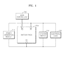
- FIG. 1 is a schematic view illustrating a structure of a vehicle including a battery pack 100a according to an embodiment of the present invention.
- the battery pack 100a may be electrically connected in parallel to a power generation module 210 and a starter motor 220 via first and second terminals P1 and P2.
- the first terminal P1 may be referred to as an external device connection terminal.
- the battery pack 100a may store charging power generated from the power generation module 210 and supply discharging power to the starter motor 220.
- the power generation module 210 may be connected to an engine (not shown) to provide power thereto, and may be connected to a driving axis of the engine to convert rotational motive power into an electrical output.
- charging power generated by the power generation module 210 may be stored in a battery module 110, as described below, via the first and second terminals P1 and P2 of the battery pack 100.
- the power generation module 210 may include a direct current (DC) generator (not shown) or an alternating current (AC) generator (not shown) and a rectifying unit (not shown), and may supply a voltage of about 15 V DC, specifically, voltage of about 14.6 V to 14.8 V DC.
- DC direct current
- AC alternating current
- DC rectifying unit
- the battery pack 100a may be used as a power unit for starting up an engine of an Idle Stop & Go (ISG) system, in which an ISG function is implemented to improve fuel efficiency.
- ISG Idle Stop & Go
- a lead storage battery applied to conventional ISG systems has problems such as a decrease in durability and life span and a decrease in charging and discharging characteristics due to frequent repetition of charging and discharging operations, and for example, a charging capacity is decreased due to repeated charging or discharging, and thus, starting up ability of an engine is degraded, and an exchange cycle of the lead storage battery is shortened.
- the battery module 110 according to the current embodiment of the present invention includes a lithium ion battery which maintains relatively uniform charging or discharging characteristics and thus has little deterioration and may be suitable for an ISG system where stopping and re-startup of an engine is repeated. Also, compared to a lead storage battery of the same charging capacity, the battery module 110 according to the current embodiment of the present invention obtains the same charging capacity with less volume than the lead storage battery, and thus, a mounting space may be reduced.
- a lithium ion battery but also a nickel metal hydride (NiMH) battery may be used as the battery module 110 according to the current embodiment of the present invention.
- NiMH nickel metal hydride
- the battery pack 100a may limit a state-of-charge (SOC) to be within a predetermined charging or discharging range to reduce a swelling proceeding speed or may conduct charging or discharging repeatedly within the charging or discharging range, thereby correcting the swelling.
- SOC state-of-charge
- a main control unit 240 is a control unit controlling the overall operation of the vehicle in which the battery pack 100a is mounted.
- the main control unit 240 is connected to the battery pack 100a via a third terminal P3 to exchange a control signal with the battery pack 100a, monitor a state of the battery pack 100a, and control an operation of the battery pack 100a.
- the power generation module 210 may refer to a concept including an alternator of a vehicle.
- An alternator not only supplies charging power to the battery pack 100a but also power to an electrical load 230 while an engine is driven.
- the starter motor 220 is driven when an engine of a vehicle is started up, and may provide an initial rotational motive power that rotates a driving axis of the engine.
- the starter motor 220 may receive stored power via the first and second terminals P1 and P2 of the battery pack 100a and rotate a driving axis of the engine when the engine is started up or when the engine is restarted after an idle stop, thereby re-driving the engine.
- starter motor 220 may be driven by a driving signal from BMS 120, as described below.
- the electrical load 230 may be connected to the battery pack 100.
- the electrical load 230 consumes power stored in the battery pack 100, may receive stored discharging power via the first and second terminals P1 and P2, and may include various components for electrical devices.
- FIG. 2 illustrates a structure of a battery pack 100a according to an embodiment of the present invention.
- the battery pack 100a may include the battery module 110, an auxiliary battery 111, a battery management system (BMS) 120, a sensor unit 130, and a selection unit 140a.
- BMS battery management system
- the battery module 110 and the auxiliary battery 111 may each include a plurality of battery cells (not shown) that are connected serially or parallel.
- the battery module 110 according to the current embodiment of the present invention is connected between the first and second terminals P1 and P2, and receives charging power and outputs discharging power.
- the battery module 110 is a general name of a structure including a plurality of battery sub-units.
- the battery rack may be regarded as the battery module 110.
- the battery tray may be regarded as the battery module 110.
- the battery module 110 may be formed of a lithium ion battery, a nickel-hydrogen battery, etc.
- the auxiliary battery 111 may be formed of a conventional lead storage battery in order to complement characteristics of the battery module 110.
- battery swelling which refers to expansion of battery cells in the battery module 110 due to an increase in an internal pressure
- battery swelling deforms an external appearance of a case of the battery pack 100a, and stability of the battery pack 100a may be problematic due to this deformation.
- the speed of battery swelling may increase when overcharging or overdischarging of the battery is repeated.
- an SOC of a battery is limited within a predetermined charging and discharging range to thereby reduce the speed at which swelling of the battery module 110 proceeds.
- charging and discharging of the battery module 110 may be repeatedly conducted within a charging or discharging range.
- the BMS 120 controls a charging and discharging process of the battery module 110.
- the BMS 120 is connected to the battery module 110, and controls charging and discharging operations of the battery module 110.
- the BMS 120 may perform functions such as overcharge protection function, over-discharging protection function, over-current protection function, over-voltage protection function, overheating protection function, and cell balancing.
- the BMS 120 may include a measuring unit that measures a voltage, a current, a temperature, a remaining amount of power, a lifespan, an SOC, or the like from the battery module 110, and may generate a control signal based on a measurement result to control external devices such as the starter motor 220 and the power generation module 210 of the current embodiment of the present invention.
- the sensor unit 130 measures a degree of swelling of the battery module 110.
- the sensor unit 130 may measure a degree of swelling of the battery module 110 by using a piezoelectric element. When using a piezoelectric element, a minute change in the battery module 110 may be precisely measured.
- the sensor unit 130 transmits a measurement result to the BMS 120.
- the selection unit 140a selectively connects a circuit between P1 and (a), (b) or (c) according to a control signal of the BMS 120.
- the selection unit 140a may include a switching device.
- the selection unit 140a may locate the switching device at (a) to connect a first terminal P1, which is a connection terminal to an external device, to the battery module 110, or locate the switching device at (b) to connect the same to the auxiliary battery 111, or may locate the switching device at (c) so that the switching device is not connected to any of devices in the battery pack 100a.
- FIG. 3 illustrates an internal structure of the BMS 120 according to an embodiment of the present invention.
- the BMS 120 includes a swelling sensing unit 121, a range limiting unit 122 and a correcting unit 123.
- the swelling sensing unit 121 receives a battery swelling measurement value from the sensor unit 130 to determine whether the degree of swelling exceeds a reference value. For example, if a degree of swelling of the battery module 110 measured by using a piezoelectric element of the sensor unit 130 is equal to or greater than a predetermined reference value, the swelling sensing unit 121 determines that the battery module 110 is swollen and a decrease in the swelling speed or correction of the swelling is required.
- the range limiting unit 122 limits an SOC of the battery module 110 to be within a charging and discharging range between a charging limit and a discharging limit according to an embodiment of the present invention to thereby reduce a proceeding speed of swelling.
- the range limiting unit 122 examines whether an SOC of the battery module 110 is a discharging limit or a charging limit, and if the SOC of the battery module 110 is a discharging limit, the switching device is located at (b) so that an external device may receive power from the auxiliary battery 111 or supply power to the auxiliary battery 111.
- the range limiting unit 122 locates the switching device at (c) to thus block connection between the external device and the battery pack 100.
- FIG. 4 is a schematic view illustrating a selection/control unit 140b according to another embodiment of the present invention.
- a battery module connection terminal (a) and an auxiliary battery connection terminal (b) are respectively connected to variable resistors R 1 and R 2 so as to be connected to a parallel connection terminal (ab).
- the range limiting unit 122 adjusts an amount of current flowing into the battery module 110 and the auxiliary battery 111 via the variable resistors R 1 and R 2 , thereby controlling a charging and discharging range.
- the range limiting unit 122 locates a switching device at (ab), and sets a resistance of the variable resistor R 1 to be greater than that of the variable resistor R 2 so that more discharging or charging current flows to the auxiliary battery 111 than to the battery module 110.
- a process of decreasing a swelling proceeding speed of the range limiting unit 122 will be further described with reference to FIGS. 5 and 6 below.
- FIG. 5 is a graph of an SOC of a typical battery.
- the BMS 120 may set a charging limit or a discharging limit.
- the charging limit may be 70% of an SOC maximum
- the discharging limit may be 30% of an SOC maximum.
- FIG. 6 is a graph illustrating charging or discharging of a battery module by limiting a range of charging or discharging, according to an embodiment of the present invention.
- the range limiting unit 122 may control such that when an SOC reaches a discharging limit L while the battery module 110 is being discharged by the electrical load 230 as illustrated in FIG. 6 , no more discharging is conducted.
- no more power may be supplied from the power generation module 210 to the battery module 110.
- FIG. 7 illustrates an internal structure of a vehicle including a battery pack 100b according to another embodiment of the present invention.
- the BMS 120 may not only limit an SOC of a battery to be within a charging or discharging range like in the embodiment of FIG. 2 , and according to another embodiment of the present invention, charging or discharging may be actively performed within the charging and discharging range to correct swelling. That is, according to the embodiment of FIG. 2 , just the SOC of the battery is limited when charging or discharging a battery via the electrical load 230 or the power generation module 210, but according to the embodiment of FIG. 7 , a swollen battery is actively corrected by repeated charging and discharging even when a vehicle is not driven.
- FIG. 7 a path, through which the BMS 120 of the battery pack 100b may transmit a signal to the power generation module 210, the starter motor 220, and the electrical load 230 via a P3 terminal, is added to Figure 1 .
- the correction unit 123 of the BMS 120 transmits a signal for driving the starter motor 220. That is, even if the user does not start up the engine of the vehicle, the starter motor 220 is driven by a driving signal of the BMS 120, and when the engine is started by the starter motor 220, the power generation module 210 supplies charging power to the battery module 110. That is, charging of the battery module 110 is performed.
- the correction unit 123 stops operation of the power generation module 210 and drives the electrical load 230 to discharge the battery module 110. That is, even when the engine is stopped, the BMS 120 may forcibly operate the electrical load 230 which may be, for example, a light, a radio, a fan, or an air conditioner, thereby discharging the battery module 110.
- the BMS 120 transmits a signal for stopping operation of the electrical load 230 and transmits a signal for driving the starter motor 220 so that the power generation module 210 supplies charging power to the battery module 110.
- Charging or discharging of the battery module 110 is repeated within a charging or discharging range in the above-described manner to thereby correct swelling of the battery module 110. If the sensing unit 130 determines that swelling of the battery module 110 is corrected, the BMS 120 stops charging or discharging of the battery module 110.
- FIG. 8 is a graph illustrating an SOC of a battery when swelling is corrected, according to an embodiment of the present invention.
- the correction unit 123 may charge the battery module 110 and when an SOC reaches a charging limit H, the battery module 110 is immediately discharged; on the other hand, when an SOC reaches a discharging limit L while discharging the battery module 110, the battery module 110 is immediately charged. According to the above-described method, the correction unit 123 may actively correct swelling of the battery module 110.
- FIG. 9 is a flowchart illustrating an operation of a reducing a proceeding speed of swelling by limiting a charging or discharging range of an SOC of a battery.
- a BMS senses whether a battery is swollen or not by using information received from a sensor unit.
- the BMS monitors an SOC of a battery module to sense a moment where an SOC of the battery module reaches a discharging limit or a charging limit.
- the selection unit connects an external device connection terminal, that is, a terminal P1, to the auxiliary battery module 111.
- the selection unit disconnects the external device connection terminal P1 from the battery module 110, for example by connecting to a dummy terminal c (operation S14).
- the SOC of the battery module is further sensed.
- the battery module is charged or discharged within a charging and discharging range between the charging limit and the discharging limit.
- FIG. 10 is a flowchart illustrating an operation of correcting swelling by charging or discharging a battery within a charging or discharging range.
- a BMS senses whether a battery is swollen by using information received from a sensor unit, and operates a correction unit.
- the BMS monitors an SOC of a battery module to sense a moment when an SOC reaches a discharging limit or a charging limit.
- the BMS transmits a driving signal to a starter motor and allows an alternator to generate charging power of the battery module in operation S24, and charges the battery in operation S25.
- the BMS transmits a driving signal to an electrical load so as to forcibly operate the electrical load in operation S26 to discharge the battery module in operation S27.
Landscapes
- Engineering & Computer Science (AREA)
- Power Engineering (AREA)
- Life Sciences & Earth Sciences (AREA)
- Sustainable Development (AREA)
- Sustainable Energy (AREA)
- Transportation (AREA)
- Mechanical Engineering (AREA)
- Chemical & Material Sciences (AREA)
- Chemical Kinetics & Catalysis (AREA)
- Electrochemistry (AREA)
- General Chemical & Material Sciences (AREA)
- Secondary Cells (AREA)
- Charge And Discharge Circuits For Batteries Or The Like (AREA)
- Battery Mounting, Suspending (AREA)
Applications Claiming Priority (1)
| Application Number | Priority Date | Filing Date | Title |
|---|---|---|---|
| US201261615647P | 2012-03-26 | 2012-03-26 |
Publications (1)
| Publication Number | Publication Date |
|---|---|
| EP2645527A1 true EP2645527A1 (fr) | 2013-10-02 |
Family
ID=47678620
Family Applications (1)
| Application Number | Title | Priority Date | Filing Date |
|---|---|---|---|
| EP13153760.7A Withdrawn EP2645527A1 (fr) | 2012-03-26 | 2013-02-01 | Bloc-batteries |
Country Status (5)
| Country | Link |
|---|---|
| US (1) | US9263900B2 (fr) |
| EP (1) | EP2645527A1 (fr) |
| JP (1) | JP2013201890A (fr) |
| KR (1) | KR20130109038A (fr) |
| CN (1) | CN103358923A (fr) |
Cited By (9)
| Publication number | Priority date | Publication date | Assignee | Title |
|---|---|---|---|---|
| EP3002850A1 (fr) * | 2014-10-02 | 2016-04-06 | SK Innovation Co., Ltd. | Procédé et dispositif de protection contre les surcharges comportant une fonction de diagnostic |
| FR3027169A1 (fr) * | 2014-10-09 | 2016-04-15 | Peugeot Citroen Automobiles Sa | Dispositif de stockage d’energie electrique pour vehicule automobile |
| EP3163672A4 (fr) * | 2014-06-30 | 2017-06-28 | Toyo Tire & Rubber Co., Ltd. | Procédé de détermination d'anomalie dans un bloc-batterie, et dispositif de détermination d'anomalie dans un bloc-batterie |
| EP3232502A4 (fr) * | 2015-06-10 | 2018-01-10 | LG Chem, Ltd. | Système et procédé de détection de gonflement d'élément de batterie |
| EP3300162A4 (fr) * | 2015-09-14 | 2018-06-06 | LG Chem, Ltd. | Système et procédé de détection de gonflement de batterie |
| WO2019025168A1 (fr) * | 2017-08-03 | 2019-02-07 | Robert Bosch Gmbh | Système accumulateur d'énergie ainsi que procédé servant à couper électriquement au moins une première unité accumulatrice d'énergie |
| IT202100005879A1 (it) * | 2021-03-12 | 2022-09-12 | Trendy S R L | Sistema di balancing attivo da energia rinnovabile o di recupero |
| US11518265B2 (en) | 2020-05-19 | 2022-12-06 | Volkswagen Aktiengesellschaft | Method for proposing a charging strategy for aging-optimized charging of an energy store of a motor vehicle, charging device and motor vehicle |
| EP4213274A4 (fr) * | 2021-07-08 | 2024-05-08 | LG Energy Solution, Ltd. | Système de gestion de batterie, bloc-batterie, véhicule électrique et procédé de gestion de batterie |
Families Citing this family (44)
| Publication number | Priority date | Publication date | Assignee | Title |
|---|---|---|---|---|
| US11397215B2 (en) | 2010-05-21 | 2022-07-26 | Qnovo Inc. | Battery adaptive charging using battery physical phenomena |
| US11791647B2 (en) | 2010-05-21 | 2023-10-17 | Qnovo Inc. | Method and circuitry to adaptively charge a battery/cell |
| US12081057B2 (en) | 2010-05-21 | 2024-09-03 | Qnovo Inc. | Method and circuitry to adaptively charge a battery/cell |
| US10389156B2 (en) | 2010-05-21 | 2019-08-20 | Qnovo Inc. | Method and circuitry to adaptively charge a battery/cell |
| US9142994B2 (en) | 2012-09-25 | 2015-09-22 | Qnovo, Inc. | Method and circuitry to adaptively charge a battery/cell |
| US11397216B2 (en) | 2010-05-21 | 2022-07-26 | Qnovo Inc. | Battery adaptive charging using a battery model |
| KR101397023B1 (ko) * | 2012-03-23 | 2014-05-20 | 삼성에스디아이 주식회사 | 배터리 팩 및 배터리 팩의 제어 방법 |
| EP2645527A1 (fr) * | 2012-03-26 | 2013-10-02 | Samsung SDI Co., Ltd. | Bloc-batteries |
| DE102012215846A1 (de) * | 2012-09-06 | 2014-03-06 | Continental Automotive Gmbh | Batterieanordnung zum Betrieb elektrischer Verbraucher in einem Fahrzeug zur Gefahrgutbeförderung |
| US9461492B1 (en) | 2013-04-19 | 2016-10-04 | Qnovo Inc. | Method and circuitry to adaptively charge a battery/cell using a charge-time parameter |
| KR101708456B1 (ko) * | 2013-10-22 | 2017-02-20 | 주식회사 엘지화학 | 압전소자를 이용한 캐패시터 충전 시스템 및 이를 포함하는 isg 시스템 |
| WO2015147977A1 (fr) * | 2014-03-24 | 2015-10-01 | General Electric Company | Surveillance de l'état d'une cellule de batterie au moyen de courants de foucault |
| JP2015217692A (ja) * | 2014-05-14 | 2015-12-07 | トヨタ自動車株式会社 | 電源制御装置 |
| US20150340899A1 (en) * | 2014-05-20 | 2015-11-26 | Ford Global Technologies, Llc | Automatic battery discharge tool |
| US10574079B1 (en) * | 2014-06-20 | 2020-02-25 | Qnovo Inc. | Wireless charging techniques and circuitry for a battery |
| CN204145050U (zh) * | 2014-07-02 | 2015-02-04 | 艾默生电气公司 | 在环境控制系统中使用的控制器 |
| CN104135051A (zh) * | 2014-07-30 | 2014-11-05 | 宇龙计算机通信科技(深圳)有限公司 | 一种终端及其供电装置 |
| JP6327046B2 (ja) * | 2014-07-31 | 2018-05-23 | 日立化成株式会社 | 電源システムおよび自動車 |
| US20160093854A1 (en) * | 2014-09-26 | 2016-03-31 | Johnson Controls Technology Company | Prismatic battery cell energy density for a lithium ion battery module |
| US11079212B2 (en) * | 2014-10-24 | 2021-08-03 | Qnovo Inc. | Circuitry and techniques for determining swelling of a battery/cell and adaptive charging circuitry and techniques based thereon |
| JP6244477B2 (ja) * | 2014-11-04 | 2017-12-06 | 本田技研工業株式会社 | 充電制御装置及び充電制御方法 |
| KR102421778B1 (ko) * | 2014-11-14 | 2022-07-14 | 삼성에스디아이 주식회사 | 이차 전지 충전 장치 |
| KR102400501B1 (ko) * | 2015-09-24 | 2022-05-20 | 삼성에스디아이 주식회사 | 무정전 전원 공급장치 |
| US10680450B2 (en) * | 2015-10-05 | 2020-06-09 | Lenovo (Singapore) Pte. Ltd. | Devices and methods to discharge battery |
| EP3377363A4 (fr) * | 2015-11-19 | 2019-08-07 | The Regents Of The University Of Michigan | Estimation d'état de pile sur la base de caractéristiques de gonflement |
| KR101685102B1 (ko) | 2016-04-27 | 2016-12-09 | 주식회사 대경산전 | 스웰링 감지가 용이한 재충전 가능 배터리 장치 |
| KR102633756B1 (ko) * | 2016-04-28 | 2024-02-05 | 삼성에스디아이 주식회사 | 배터리 팩 및 배터리 팩의 충전 방법 |
| DE102016214484A1 (de) * | 2016-08-04 | 2018-02-08 | Audi Ag | Verfahren zum Vorbereiten einer Batterie eines Kraftfahrzeugs für einen Transport und Kraftfahrzeug |
| US10333307B2 (en) * | 2016-12-14 | 2019-06-25 | Nec Corporation | Machine learning based demand charge |
| CN110392956B (zh) * | 2017-01-09 | 2023-06-23 | 米沃奇电动工具公司 | 电池组 |
| JP6864536B2 (ja) * | 2017-04-25 | 2021-04-28 | 株式会社東芝 | 二次電池システム、充電方法、プログラム、及び車両 |
| TWI689152B (zh) * | 2018-03-09 | 2020-03-21 | 華碩電腦股份有限公司 | 電池管理裝置 |
| KR102259413B1 (ko) * | 2018-03-12 | 2021-06-01 | 주식회사 엘지에너지솔루션 | 과방전 방지 장치 |
| US10819122B2 (en) | 2018-04-05 | 2020-10-27 | Lenovo (Singapore) Pte. Ltd. | Systems and methods to use cell balancing resistor(s) of battery pack to reduce charge level of battery cells |
| CN110884387A (zh) * | 2018-09-11 | 2020-03-17 | 南昌大学 | 智能电动车 |
| EP3826100A4 (fr) * | 2019-01-18 | 2021-12-22 | LG Chem, Ltd. | Appareil et procédé de gestion de batterie |
| US12007232B2 (en) | 2019-05-30 | 2024-06-11 | Google Llc | Methods to continuously monitor battery cell physical health and swell |
| KR20210070076A (ko) | 2019-12-04 | 2021-06-14 | 주식회사 엘지에너지솔루션 | 배터리 관리 시스템, 배터리 팩 및 배터리 관리 방법 |
| CN113746189A (zh) * | 2020-05-29 | 2021-12-03 | 天扬精密科技股份有限公司 | 启动电池与快速储能模块并联出力比配置系统及其方法 |
| US11429167B2 (en) | 2020-07-17 | 2022-08-30 | Lenovo (Singapore) Pte. Ltd. | Techniques to decommission battery based on user command |
| US12081060B2 (en) | 2020-09-11 | 2024-09-03 | Robert Bosch Gmbh | Minimizing irreversible swelling during battery charging |
| CN113805088B (zh) * | 2021-08-30 | 2024-08-16 | 歌尔科技有限公司 | 电池膨胀系数校准方法及装置、电池健康状态检测方法 |
| KR20230055030A (ko) * | 2021-10-18 | 2023-04-25 | 주식회사 엘지에너지솔루션 | 스웰링 감지 수단을 구비한 배터리 모듈 |
| CN118648214A (zh) * | 2022-07-25 | 2024-09-13 | 宁德时代新能源科技股份有限公司 | 电池充电的控制方法、装置、设备和介质 |
Citations (4)
| Publication number | Priority date | Publication date | Assignee | Title |
|---|---|---|---|---|
| EP0428130A2 (fr) * | 1989-11-13 | 1991-05-22 | Fuji Jukogyo Kabushiki Kaisha | Système de charge de batterie pour moteur-générateur |
| US6281663B1 (en) * | 1999-11-11 | 2001-08-28 | Honda Giken Kogyo Kabushiki Kaisha | Battery charging method |
| US20080315843A1 (en) * | 2007-06-25 | 2008-12-25 | Ramesh Chandra Bhardwaj | Methods and systems for battery charging management |
| US20100072953A1 (en) * | 2008-09-24 | 2010-03-25 | Toyota Jidosha Kabushiki Kaisha | Electrically-driven vehicle and charge control system |
Family Cites Families (48)
| Publication number | Priority date | Publication date | Assignee | Title |
|---|---|---|---|---|
| US3281640A (en) * | 1963-04-19 | 1966-10-25 | Dynamic Instr Corp | Battery and charging means therefor |
| DE2128510A1 (de) * | 1971-06-08 | 1972-12-14 | Sonnenschein Accumulatoren | Stromversorgungseinrichtung |
| TW269727B (en) * | 1995-04-03 | 1996-02-01 | Electrosource Inc | Battery management system |
| AUPO917297A0 (en) * | 1997-09-15 | 1997-10-09 | Commonwealth Scientific And Industrial Research Organisation | Charging of batteries |
| US5828201A (en) * | 1997-10-30 | 1998-10-27 | Lockheed Martin Corporation | Method for maintaining the charge capacity of traction battery modules of a hybrid electric vehicle |
| US6037751A (en) * | 1998-07-01 | 2000-03-14 | Gnb Technologies, Inc. | Method and apparatus for charging batteries |
| JP3212963B2 (ja) * | 1999-03-16 | 2001-09-25 | 松下電器産業株式会社 | 二次電池制御回路 |
| JP2001021626A (ja) * | 1999-07-02 | 2001-01-26 | Yazaki Corp | 温度センサを用いないガッシング判定機能を有するバッテリの容量測定装置 |
| JP2001021625A (ja) * | 1999-07-02 | 2001-01-26 | Yazaki Corp | 温度を考慮したガッシング電圧を用いたバッテリの容量測定装置 |
| US6819011B2 (en) | 2002-11-14 | 2004-11-16 | Fyre Storm, Inc. | Switching power converter controller with watchdog timer |
| EP1422420B1 (fr) * | 2002-11-25 | 2009-06-03 | Ford Global Technologies, LLC | Mécanisme de blocage pour le vilebrequin d'un moteur à combustion interne |
| JP4314223B2 (ja) * | 2004-09-24 | 2009-08-12 | 株式会社東芝 | 回生用蓄電システム、蓄電池システムならびに自動車 |
| KR100579377B1 (ko) | 2004-10-28 | 2006-05-12 | 삼성에스디아이 주식회사 | 이차 전지 |
| KR100692404B1 (ko) * | 2004-12-21 | 2007-03-09 | 현대자동차주식회사 | 메모리효과를 방지하기 위한 배터리 충전상태 계산 알고리즘 |
| KR100889244B1 (ko) | 2005-04-20 | 2009-03-17 | 주식회사 엘지화학 | 압전 센서가 내장된 이차전지 모듈 |
| EP1878071B1 (fr) * | 2005-05-02 | 2012-08-15 | Lg Chem, Ltd. | Bloc de batteries de moyenne ou grande taille ameliore pour securite accrue |
| JP5254568B2 (ja) * | 2007-05-16 | 2013-08-07 | 日立ビークルエナジー株式会社 | セルコントローラ、電池モジュールおよび電源システム |
| KR20090013867A (ko) | 2007-08-03 | 2009-02-06 | 현대자동차주식회사 | 전기 차량용 고전압 배터리의 안전장치 |
| TW200913433A (en) * | 2007-09-10 | 2009-03-16 | J Tek Inc | Scattered energy storage control system |
| US7830125B2 (en) * | 2007-09-20 | 2010-11-09 | Nexergy, Inc. | Anti-swell protection circuit for battery cells |
| KR101128423B1 (ko) * | 2008-04-28 | 2012-03-23 | 에스케이이노베이션 주식회사 | 전기자동차용 2차 전지의 안전 스위치 및 이를 이용한전기자동차용 2차 전지의 충방전 시스템 |
| WO2010083291A1 (fr) * | 2009-01-14 | 2010-07-22 | Indy Power Systems Llc | Système de gestion de cellule |
| US8216713B2 (en) | 2009-02-25 | 2012-07-10 | Sb Limotive Co., Ltd. | Battery housing formed with cooling passages and battery pack having the same |
| US8183826B2 (en) * | 2009-05-15 | 2012-05-22 | Battelle Memorial Institute | Battery charging control methods, electric vehicle charging methods, battery charging apparatuses and rechargeable battery systems |
| US8112208B2 (en) * | 2009-05-28 | 2012-02-07 | Ford Global Technologies, Llc | Engine speed reduction preparatory to an engine restart |
| CN101651239B (zh) * | 2009-09-17 | 2011-11-23 | 钟阳 | 对多组蓄电池充电方法和其控制系统 |
| US8415926B2 (en) * | 2009-10-19 | 2013-04-09 | Apple Inc. | In-situ battery health detector and end-of-life indicator |
| KR101039679B1 (ko) * | 2009-11-17 | 2011-06-09 | 현대자동차주식회사 | 마일드 하이브리드 시스템 및 그 제어 방법 |
| KR101093928B1 (ko) * | 2009-11-26 | 2011-12-13 | 삼성에스디아이 주식회사 | 배터리 셀의 고온 스웰링을 방지할 수 있는 배터리 팩 및 그 방법 |
| KR101057542B1 (ko) * | 2010-01-26 | 2011-08-17 | 에스비리모티브 주식회사 | 배터리 관리 시스템 및 그 구동 방법 |
| JP5499872B2 (ja) * | 2010-04-21 | 2014-05-21 | ソニー株式会社 | バッテリー制御装置、バッテリー制御方法及びプログラム |
| KR101147231B1 (ko) * | 2010-07-23 | 2012-05-18 | 삼성에스디아이 주식회사 | 전지 팩 및 그의 충방전 제어 방법 |
| US8513919B2 (en) * | 2010-07-28 | 2013-08-20 | Apple Inc. | Swelling management in batteries for portable electronic devices |
| KR101220367B1 (ko) * | 2010-08-31 | 2013-01-09 | 현대자동차주식회사 | 플러그인 하이브리드 자동차의 충전장치 및 방법 |
| KR20120021094A (ko) * | 2010-08-31 | 2012-03-08 | 현대자동차주식회사 | 하이브리드 차량의 변속 제어장치 및 방법 |
| KR101241221B1 (ko) * | 2010-12-06 | 2013-03-13 | 주식회사 이지트로닉스 | 마일드 하이브리드 차량용 충전 장치 |
| US8952823B2 (en) * | 2011-01-20 | 2015-02-10 | Indiana University Research And Technology Corporation | Battery early warning and monitoring system |
| KR101330615B1 (ko) * | 2011-04-26 | 2013-11-18 | 로베르트 보쉬 게엠베하 | 이차 전지 |
| KR20120136826A (ko) * | 2011-06-10 | 2012-12-20 | 현대자동차주식회사 | 배터리 과충전 방지 장치 |
| KR20130016875A (ko) * | 2011-08-09 | 2013-02-19 | 현대자동차주식회사 | 하이브리드 차량 |
| US8854012B2 (en) * | 2011-08-25 | 2014-10-07 | Apple Inc. | Management of high-voltage lithium-polymer batteries in portable electronic devices |
| EP2826128A4 (fr) * | 2012-03-16 | 2016-03-23 | Boston Power Inc | Procédé et système d'équilibrage de cellules par courant de court-circuit variable |
| EP2641783B1 (fr) * | 2012-03-20 | 2016-04-20 | Samsung SDI Co., Ltd. | Bloc-batteries et son procédé de commande |
| KR101312263B1 (ko) * | 2012-03-23 | 2013-09-25 | 삼성에스디아이 주식회사 | 운송 수단 및 그 제어 방법 |
| KR101397023B1 (ko) * | 2012-03-23 | 2014-05-20 | 삼성에스디아이 주식회사 | 배터리 팩 및 배터리 팩의 제어 방법 |
| EP2645527A1 (fr) * | 2012-03-26 | 2013-10-02 | Samsung SDI Co., Ltd. | Bloc-batteries |
| EP2645467A1 (fr) * | 2012-03-26 | 2013-10-02 | Samsung SDI Co., Ltd. | Système de charge de bloc batterie et son procédé de commande |
| US9263908B2 (en) * | 2012-06-26 | 2016-02-16 | Samsung Sdi Co., Ltd. | Battery pack having linear voltage profile, and SOC algorithm applying to the battery pack |
-
2013
- 2013-02-01 EP EP13153760.7A patent/EP2645527A1/fr not_active Withdrawn
- 2013-02-21 US US13/773,525 patent/US9263900B2/en not_active Expired - Fee Related
- 2013-03-11 KR KR1020130025747A patent/KR20130109038A/ko not_active Application Discontinuation
- 2013-03-21 JP JP2013058087A patent/JP2013201890A/ja active Pending
- 2013-03-22 CN CN2013100952113A patent/CN103358923A/zh active Pending
Patent Citations (4)
| Publication number | Priority date | Publication date | Assignee | Title |
|---|---|---|---|---|
| EP0428130A2 (fr) * | 1989-11-13 | 1991-05-22 | Fuji Jukogyo Kabushiki Kaisha | Système de charge de batterie pour moteur-générateur |
| US6281663B1 (en) * | 1999-11-11 | 2001-08-28 | Honda Giken Kogyo Kabushiki Kaisha | Battery charging method |
| US20080315843A1 (en) * | 2007-06-25 | 2008-12-25 | Ramesh Chandra Bhardwaj | Methods and systems for battery charging management |
| US20100072953A1 (en) * | 2008-09-24 | 2010-03-25 | Toyota Jidosha Kabushiki Kaisha | Electrically-driven vehicle and charge control system |
Cited By (13)
| Publication number | Priority date | Publication date | Assignee | Title |
|---|---|---|---|---|
| EP3163672A4 (fr) * | 2014-06-30 | 2017-06-28 | Toyo Tire & Rubber Co., Ltd. | Procédé de détermination d'anomalie dans un bloc-batterie, et dispositif de détermination d'anomalie dans un bloc-batterie |
| US10651662B2 (en) | 2014-10-02 | 2020-05-12 | Sk Innovation Co., Ltd. | Overcharge protection device and method including diagnostic function |
| EP3002850A1 (fr) * | 2014-10-02 | 2016-04-06 | SK Innovation Co., Ltd. | Procédé et dispositif de protection contre les surcharges comportant une fonction de diagnostic |
| FR3027169A1 (fr) * | 2014-10-09 | 2016-04-15 | Peugeot Citroen Automobiles Sa | Dispositif de stockage d’energie electrique pour vehicule automobile |
| EP3232502A4 (fr) * | 2015-06-10 | 2018-01-10 | LG Chem, Ltd. | Système et procédé de détection de gonflement d'élément de batterie |
| US10587016B2 (en) | 2015-06-10 | 2020-03-10 | Lg Chem, Ltd. | System and method for sensing battery cell swelling |
| US10479213B2 (en) | 2015-09-14 | 2019-11-19 | Lg Chem, Ltd. | Battery swelling sensing system and method |
| EP3300162A4 (fr) * | 2015-09-14 | 2018-06-06 | LG Chem, Ltd. | Système et procédé de détection de gonflement de batterie |
| WO2019025168A1 (fr) * | 2017-08-03 | 2019-02-07 | Robert Bosch Gmbh | Système accumulateur d'énergie ainsi que procédé servant à couper électriquement au moins une première unité accumulatrice d'énergie |
| CN110914096A (zh) * | 2017-08-03 | 2020-03-24 | 罗伯特·博世有限公司 | 蓄能系统以及用于将至少一个第一蓄能单元电分离的方法 |
| US11518265B2 (en) | 2020-05-19 | 2022-12-06 | Volkswagen Aktiengesellschaft | Method for proposing a charging strategy for aging-optimized charging of an energy store of a motor vehicle, charging device and motor vehicle |
| IT202100005879A1 (it) * | 2021-03-12 | 2022-09-12 | Trendy S R L | Sistema di balancing attivo da energia rinnovabile o di recupero |
| EP4213274A4 (fr) * | 2021-07-08 | 2024-05-08 | LG Energy Solution, Ltd. | Système de gestion de batterie, bloc-batterie, véhicule électrique et procédé de gestion de batterie |
Also Published As
| Publication number | Publication date |
|---|---|
| US20130249494A1 (en) | 2013-09-26 |
| KR20130109038A (ko) | 2013-10-07 |
| US9263900B2 (en) | 2016-02-16 |
| JP2013201890A (ja) | 2013-10-03 |
| CN103358923A (zh) | 2013-10-23 |
Similar Documents
| Publication | Publication Date | Title |
|---|---|---|
| EP2645527A1 (fr) | Bloc-batteries | |
| EP2645467A1 (fr) | Système de charge de bloc batterie et son procédé de commande | |
| KR101397023B1 (ko) | 배터리 팩 및 배터리 팩의 제어 방법 | |
| EP2083494B1 (fr) | Dispositif de détection d'anomalie pour batterie, procédé de détection d'anomalie pour batterie, programme de détection d'anomalie pour batterie, et support d'enregistrement contenant le programme de détection d'anomalie pour batterie | |
| EP2033003B1 (fr) | Détermination de limites prédictives d'énergie de batterie | |
| JP5312768B2 (ja) | 電池システム | |
| US7634369B2 (en) | Battery management system (BMS) and driving method thereof | |
| JP5488877B2 (ja) | 電動工具 | |
| US9263908B2 (en) | Battery pack having linear voltage profile, and SOC algorithm applying to the battery pack | |
| KR101696160B1 (ko) | 전압 측정을 통한 배터리 랙 파손 방지 장치, 시스템 및 방법 | |
| KR101420340B1 (ko) | 차량 운행 시스템, 및 이의 제어방법 | |
| KR101312263B1 (ko) | 운송 수단 및 그 제어 방법 | |
| US9350186B2 (en) | Battery pack | |
| US8810201B2 (en) | Battery management system and battery management method | |
| TW201203658A (en) | Assembled battery and method of controlling assembled battery | |
| JP2013193738A (ja) | バッテリーパック及びバッテリーパックの制御方法 | |
| KR20170004499A (ko) | 배터리 팩의 전류 측정 방법 | |
| US20140159664A1 (en) | Method of manufacturing battery pack and battery pack | |
| CN109565181B (zh) | 电池组 | |
| JP3766076B2 (ja) | 電池充電装置 | |
| KR101472886B1 (ko) | 전지팩의 전압 밸런싱 장치 및 방법 | |
| KR20240107388A (ko) | 하이브리드 밸런싱하는 배터리 관리 시스템 및 및 이를 포함하는 배터리 팩 및 전기 차량 | |
| JP2002010504A (ja) | 電気自動車の電源装置 | |
| JP2001313088A (ja) | パック電池 |
Legal Events
| Date | Code | Title | Description |
|---|---|---|---|
| PUAI | Public reference made under article 153(3) epc to a published international application that has entered the european phase |
Free format text: ORIGINAL CODE: 0009012 |
|
| AK | Designated contracting states |
Kind code of ref document: A1 Designated state(s): AL AT BE BG CH CY CZ DE DK EE ES FI FR GB GR HR HU IE IS IT LI LT LU LV MC MK MT NL NO PL PT RO RS SE SI SK SM TR |
|
| AX | Request for extension of the european patent |
Extension state: BA ME |
|
| 17P | Request for examination filed |
Effective date: 20131218 |
|
| RBV | Designated contracting states (corrected) |
Designated state(s): AL AT BE BG CH CY CZ DE DK EE ES FI FR GB GR HR HU IE IS IT LI LT LU LV MC MK MT NL NO PL PT RO RS SE SI SK SM TR |
|
| STAA | Information on the status of an ep patent application or granted ep patent |
Free format text: STATUS: THE APPLICATION HAS BEEN WITHDRAWN |
|
| 18W | Application withdrawn |
Effective date: 20160616 |