EP2644946A1 - Engrenages magnétiques variables - Google Patents
Engrenages magnétiques variables Download PDFInfo
- Publication number
- EP2644946A1 EP2644946A1 EP13160951.3A EP13160951A EP2644946A1 EP 2644946 A1 EP2644946 A1 EP 2644946A1 EP 13160951 A EP13160951 A EP 13160951A EP 2644946 A1 EP2644946 A1 EP 2644946A1
- Authority
- EP
- European Patent Office
- Prior art keywords
- rotor
- power
- gear
- magnetic
- engine
- Prior art date
- Legal status (The legal status is an assumption and is not a legal conclusion. Google has not performed a legal analysis and makes no representation as to the accuracy of the status listed.)
- Granted
Links
Images


Classifications
-
- H—ELECTRICITY
- H02—GENERATION; CONVERSION OR DISTRIBUTION OF ELECTRIC POWER
- H02K—DYNAMO-ELECTRIC MACHINES
- H02K49/00—Dynamo-electric clutches; Dynamo-electric brakes
- H02K49/10—Dynamo-electric clutches; Dynamo-electric brakes of the permanent-magnet type
- H02K49/102—Magnetic gearings, i.e. assembly of gears, linear or rotary, by which motion is magnetically transferred without physical contact
-
- F—MECHANICAL ENGINEERING; LIGHTING; HEATING; WEAPONS; BLASTING
- F16—ENGINEERING ELEMENTS AND UNITS; GENERAL MEASURES FOR PRODUCING AND MAINTAINING EFFECTIVE FUNCTIONING OF MACHINES OR INSTALLATIONS; THERMAL INSULATION IN GENERAL
- F16H—GEARING
- F16H49/00—Other gearings
- F16H49/005—Magnetic gearings with physical contact between gears
-
- H—ELECTRICITY
- H02—GENERATION; CONVERSION OR DISTRIBUTION OF ELECTRIC POWER
- H02K—DYNAMO-ELECTRIC MACHINES
- H02K51/00—Dynamo-electric gears, i.e. dynamo-electric means for transmitting mechanical power from a driving shaft to a driven shaft and comprising structurally interrelated motor and generator parts
-
- H—ELECTRICITY
- H02—GENERATION; CONVERSION OR DISTRIBUTION OF ELECTRIC POWER
- H02K—DYNAMO-ELECTRIC MACHINES
- H02K7/00—Arrangements for handling mechanical energy structurally associated with dynamo-electric machines, e.g. structural association with mechanical driving motors or auxiliary dynamo-electric machines
- H02K7/10—Structural association with clutches, brakes, gears, pulleys or mechanical starters
- H02K7/11—Structural association with clutches, brakes, gears, pulleys or mechanical starters with dynamo-electric clutches
-
- H—ELECTRICITY
- H02—GENERATION; CONVERSION OR DISTRIBUTION OF ELECTRIC POWER
- H02K—DYNAMO-ELECTRIC MACHINES
- H02K7/00—Arrangements for handling mechanical energy structurally associated with dynamo-electric machines, e.g. structural association with mechanical driving motors or auxiliary dynamo-electric machines
- H02K7/18—Structural association of electric generators with mechanical driving motors, e.g. with turbines
- H02K7/1807—Rotary generators
- H02K7/1823—Rotary generators structurally associated with turbines or similar engines
- H02K7/183—Rotary generators structurally associated with turbines or similar engines wherein the turbine is a wind turbine
- H02K7/1838—Generators mounted in a nacelle or similar structure of a horizontal axis wind turbine
-
- Y—GENERAL TAGGING OF NEW TECHNOLOGICAL DEVELOPMENTS; GENERAL TAGGING OF CROSS-SECTIONAL TECHNOLOGIES SPANNING OVER SEVERAL SECTIONS OF THE IPC; TECHNICAL SUBJECTS COVERED BY FORMER USPC CROSS-REFERENCE ART COLLECTIONS [XRACs] AND DIGESTS
- Y02—TECHNOLOGIES OR APPLICATIONS FOR MITIGATION OR ADAPTATION AGAINST CLIMATE CHANGE
- Y02E—REDUCTION OF GREENHOUSE GAS [GHG] EMISSIONS, RELATED TO ENERGY GENERATION, TRANSMISSION OR DISTRIBUTION
- Y02E10/00—Energy generation through renewable energy sources
- Y02E10/70—Wind energy
- Y02E10/72—Wind turbines with rotation axis in wind direction
Definitions
- the present invention relates to magnetic gears, and in particular to the control of the gear ratio of magnetic gears.
- Magnetic gears are known in which input and output rotors are provided with respective sets of magnetic pole pairs at different spacings, and a set of ferromagnetic pole pieces is arranged between the input and output rotors to modulate the magnetic field and allow the input rotor to drive the output rotor with a gear ratio which depends on the ratio of the spacings of the two sets of magnetic poles and the spacing of the pole pieces.
- the present invention provides a magnetic gear comprising: a first movable member having a first set of magnetic poles, a second movable member having a second set of magnetic poles, and a third movable member having a set of pole pieces; wherein the first and second members have magnetic poles at different spacings and the pole pieces are arranged to modulate the magnetic field acting between the magnetic poles, and control means arranged to control rotation of one of the members so as to vary the gear ratio between the other two members
- the movable members may comprise rotors or, in a linear system, translators.
- the present invention further provides a power generation system comprising an input member, a generator, and a magnetic gear coupling the input member to the generator, wherein the magnetic gear is a gear according to the invention.
- the present invention further provides a power train system comprising a prime mover, a load, and a magnetic gear coupling the prime mover to the load, wherein the magnetic gear is a gear according to the invention.
- the present invention further provides a power train system comprising an engine, an output member, a magnetic gear connecting the engine to the output member, an energy storage system, and control means arranged to control the flow of power from the output member to the energy storage system and from the energy storage system to the output member, wherein the magnetic gear comprises a first rotor having a first set of magnetic poles, a second rotor having a second set of magnetic poles, and a third rotor having a set of pole pieces, the first and second rotors have different numbers of magnetic poles, the pole pieces are arranged to modulate the magnetic field acting between the magnetic poles, and the control means is arranged to control rotation of one of the rotors so as to vary the gear ratio between the other two rotors.
- the magnetic gear comprises a first rotor having a first set of magnetic poles, a second rotor having a second set of magnetic poles, and a third rotor having a set of pole pieces, the first and second rotors have different numbers of
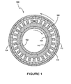
- a known rotary magnetic gear 100 comprises a first or inner rotor 102, a second or outer rotor 104 having a common axis of rotation with the first rotor 102, and a number of pole pieces 106 of ferromagnetic material supported between the rotors 102, 104.
- the first rotor 102 comprises a support 108 carrying a first set of permanent magnets 110, arranged with their north and south poles at their radially inner and outer ends, and orientated with alternating polarity so that each of the magnets 110 has its poles facing in the opposite direction to the magnets on either side of it.
- the first rotor 102 comprises eight permanent magnets, or four pole-pairs, arranged to produce a spatially varying magnetic field.
- the second rotor 104 comprises a support 112 carrying a second set of permanent magnets 114, again arranged with their poles facing radially inwards and outwards, and with alternating polarity.
- the second rotor 104 comprises 46 permanent magnets or 23 pole-pairs arranged to produce a spatially varying field.
- the first and second sets of permanent magnets therefore include different numbers of magnets. Accordingly, without any modulation of the magnetic fields they produce, there would be little or no useful magnetic coupling or interaction between the two sets of permanents magnets 110 and 114 such that rotation of one rotor would not cause rotation of the other rotor.
- the pole pieces 106 which are supported in a cylindrical non-magnetic support 116, are used to control the way in which the fields of the permanent magnets 110 and 114 interact.
- the pole pieces 106 modulate the magnetic fields of the permanent magnets 110 and 114 so that they interact to the extent that rotation of one rotor will induce rotation of the other rotor in a geared manner.
- the number of pole pieces is chosen to be equal to the sum of the number of pole-pairs of the two sets of permanent magnets. Rotation of the first rotor 102 at a speed ⁇ 1 will induce rotation of the second rotor 104 at a speed ⁇ 2 where ⁇ 1 > ⁇ 2 .
- the ratio between the speeds of rotation ⁇ 1 and ⁇ 2 i.e.
- the gearing ratio of the coupling is equal to the ratio between the numbers of pole pairs of the magnets 110 and 114 on the first and second rotors 102, 104.
- the gear can operate in reverse, so that rotation of the second rotor 104 will cause rotation of the first rotor at a higher speed.
- a magnetic gear 200 comprises three coaxial rotors: a cylindrical inner rotor 202 carrying a first set of magnets 210 providing a first set of magnetic pole pairs, a cylindrical outer rotor 204 carrying a second set of magnets 214 providing a second set of pole pairs, and a third cylindrical rotor 216 located radially between the inner and outer rotors 202, 204, which carries the set of pole pieces 206.
- the magnets 210, 214 and pole pieces 206 are spaced as in the coupling of Figure 1 .
- the inner rotor 202 is supported on an input shaft 220 so as to be rotatable therewith, and the outer rotor 204 is supported on an output shaft 222 so as to be rotatable therewith.
- the pole piece rotor 216 is rotatably supported on the input shaft 220 by means of a bearing 224.
- the third rotor 216 is therefore rotatable relative to, and independently of, the inner and outer rotors 202, 204.
- a drive motor 230 is drivingly connected by a mechanical transmission 231 to the pole piece rotor 216 so that it can rotate the pole piece rotor 216 at a speed which can be controlled and varied to control the gear ratio of the gear. If the drive motor 230 is switched off or held stationary, then the pole piece rotor 216 is held stationary and the coupling operates like the coupling of Figure 1 .
- the gear ratio between the inner rotor 202 and outer rotor 204 can be adjusted by adjusting the speed of the pole-piece rotor 216.
- the gear can operate in reverse, with the shaft 222 forming the input shaft, the outer rotor 204 forming the input rotor, the shaft 220 forming the output shaft, and the inner rotor 202 forming the output rotor.
- any one of the rotors can be used to control gear ratio between the other two rotors, and hence any two of the rotors can be selected as the input and output rotors with the third acting as the gear ratio control rotor.
- the spacing of the rotors, magnetic poles and pole pieces is the same as in the first embodiment, and corresponding parts are indicated by the same reference numerals increased by 100.
- the difference is that in this embodiment, while the outer rotor 304 is again directly connected to the output shaft 322, the pole-piece rotor 316 is connected by a mechanical transmission in the form of drive teeth 317 to the input shaft 320, and the inner rotor 302 is directly connected to the output shaft of the electric motor 330. Therefore in this embodiment the inner rotor 302 forms the gear ratio control rotor, and the pole piece rotor 316 and outer rotor 304 form the input and output rotors.
- the spacing of the rotors, magnetic poles and pole pieces is again the same as in the first embodiment, and corresponding parts are indicated by the same reference numerals as in Figure 5 again increased by 100.
- the inner rotor 402 and pole-piece rotor 416 form the input and output rotors and are connected to the input and output shafts 420, 422, and the outer rotor 404 is coupled by a mechanical transmission 431 to the motor 430 and forms the gear ratio control rotor.
- the inner rotor 502 with its associated set of magnets 510, and the pole-piece rotor 516 carrying the pole pieces 506 form the input and output rotors
- the outer rotor 504 forms the gear ratio control rotor, as in the embodiment of Figure 6 .
- the outer rotor 504 is driven by a permanent magnet electrical machine.
- the outer rotor 504 includes an inner array of magnets 514 which cooperate with the pole pieces 506 and the magnets on the inner rotor 502 to provide the gearing, and an outer array of magnets 515 which form part of the permanent magnet electrical machine.
- a stator 540 is provided radially outside the outer rotor 514, and comprises a series of coils 542 wound on ferromagnetic cores 544.
- the current flowing in these coils can be controlled to control the driving torque applied to the outer rotor 504 via the outer array of magnets 515. This enables the speed of rotation of the outer rotor 504 to be controlled, and hence the gear ratio of the gear to be varied and controlled.
- the outer magnet array 515 has a different number of poles than the inner magnet array 514. It is an advantage of having the two arrays that the gear and the electric motor can be tuned independently of each other. However, the outer magnet array 515 could have an identical number of poles to the inner array 514. In this case, it is possible to combine both magnet arrays into a single magnet array, which may be held in a non-magnetic holding structure
- a further embodiment of the invention comprises a wind turbine generator system.
- the system comprises a turbine rotor 650 which has a number of blades 652 arranged to be rotated by the wind at variable speed.
- the turbine rotor 650 is connected via a mechanical transmission 654 to the input rotor 602 of a variable gear ratio magnetic coupling 600 which corresponds to that of Figure 7 with corresponding parts indicated by the same reference numerals increased by 100.
- the output rotor 616, of the coupling which is the pole piece rotor, is connected to a constant speed electrical generator 656 which is directly connected to the three-phase electrical grid 658.
- the coils 642 of the electrical machine are connected to the electrical grid through a control system 660 which includes a power-electronics converter.
- the control system 660 is arranged to control the speed of the outer rotor 604, in order to change the gear ratio of the variable gear 600 so that the variable speed of the input rotor 602 is always matched to the constant speed of the output rotor 616.
- the torque which must be applied on the outer rotor 604 by the electrical machine 642, 615 is governed by the torque on the blades, and is always in an identical direction which does not depend on wind speed.
- the speed and direction at which the outer rotor 604 is rotated by the electrical machine 642,615 is varied as a function of the wind speed.
- the control system 660 is thus arranged to take power from the grid 658 to make the electrical machine operate as a motor when it drives the outer, gear ratio controlling, rotor 614 in the same direction to the torque, or to provide power to the grid to make the electrical machine operate as a generator when it drives the outer rotor 614 in the opposite direction to the torque.
- the electrical machine therefore acts as a motor/generator under the control of the control system 660.
- the control system includes speed sensors arranged to sense the speed of each of the rotors 602 and 604 to enable it to provide the required speed control.
- the required gear ratio between the speed of the blades and the speed of the main generator 656 is equal to the nominal gear ratio of the drive train, which results from the combination of the fixed gear and the variable gear with a stationary outer rotor 604.
- the motor/generator 642, 615 is controlled to apply a torque on the outer rotor 604 and to keep the outer rotor 604 stationary, and there is no power flow between the motor/generator and the variable gear.
- the required gear ratio between the speed of the blades 652 and the constant speed of the main generator 656 is greater than the nominal gear ratio of the drive train.
- the motor/generator 615/642 is operated to rotate the outer rotor 604 of the variable gear to adjust the overall gear ratio, while the direction of the torque that the motor/generator applies on the outer rotor 604 remains unchanged. Therefore, power is taken from the grid 658 into the electrical machine 615, 642, i.e. the electrical machine 615, 642 in the variable gear 600 operates as a motor. This power then flows through the main electrical generator 656 back into the grid 658. The power through the main electrical generator 656 is greater than the total generated power.
- the required gear ratio between the speed of the blades 652 and the constant speed of the main generator 656 is smaller than the nominal gear ratio of the drive train.
- the motor/generator 615/642 is operated to rotate the outer rotor 604 of the variable gear to adjust the overall gear ratio in a direction which is opposite to the direction of rotation at low wind speeds, while the direction of the torque that the motor/generator applies on the outer rotor 604 remains unchanged. Therefore, the electrical machine 615, 642 works as a generator. Part of the available wind power flows through the variable gear 600 and its electrical machine into the grid, and the remainder of the available power flows through the main electrical generator 656. The power through the main generator 656 is therefore smaller than the total generated power.
- the motor/generator 615, 642 works as a generator and therefore assists the main electrical generator, the main electrical generator 656 can be smaller and cheaper.
- This arrangement allows for a constant speed electrical generator 656 to be directly connected to the grid 658, whilst the blades 652 can operate at a speed that maximizes energy capture. Therefore there is no need for power electronics between the electrical generator 656 and the electrical grid 658.
- variable gear 600 The power needed to control the variable gear 600 depends on the wind speed, but is generally no more than 25% of the power which is generated by the entire turbine 650.
- the power electronics 660 in the entire system is therefore much smaller than would be required if no variable gear was used. Also, because most of the power does not go through power electronics, the efficiency is high.
- the motor/generator 642, 615 need not be connected to the grid through a controller 660, but can be connected to a separate external power supply.
- a controller 660 can be connected to a separate external power supply.
- Such an arrangement could for example be utilized in power generation systems which work in island operation, where the grid is absent at the start of the operation, such that, for example, an additional battery pack or a separate power source is required to operate the electrical machine 615, 642 at start-up.
- the electrical machine 615, 642 could be connected to a separate power supply in continuous operation.
- a further embodiment of the invention is also a wind turbine generator system similar to that of Figure 8 , with corresponding parts indicated by the same reference numerals increased by 100.
- the outer rotor 704 only has one set of magnets 714 and the outer rotor 704 is connected to the output shaft 722 by a variable coupling 760 which controls the speed of the outer rotor 704 dependent on the speed of the output shaft 722.
- the coupling 760 has at least one of its rotors 760a connected to the outer rotor 704 and one of its rotors 760b connected to the output shaft 722.
- the system further requires speed sensors to detect the speed of the output shaft or input shaft so as to control the variable coupling 760 appropriately and apply the correct feedback.
- om a is the speed of the rotor 760a of the coupling which is connected to the outer rotor 704 of the variable gear
- om b is the speed of the rotor 760b of the coupling which is connected to the output shaft 722
- k is a characteristic of the coupling.
- the coupling is further arranged so that the proportional constant k can be varied, such that the torque between the rotors can be varied for a given speed difference between the rotors 760a and 760b. For example, this could be achieved in an eddy current coupling by altering the mechanical airgap between the rotors 760a and 760b.
- the output rotor of the variable gear 716 is connected to the main generator 756 and is controlled to operate at a constant speed, while the input rotor 702 operates at a speed which is a function of the wind speed. Therefore, the speed of the outer rotor of the variable gear, and hence the difference of the speeds between the rotors 760a and 760b of the coupling, are dependent on the wind speed. Further, the torque which is required on the outer rotor 704 of the variable gear is governed by the torque on the blades 750, which is dependent on the wind speed.
- the control system aims to find a value k for each wind speed, for which the difference in speed between the rotors of the coupling 760a and 760b generates the required torque on the outer rotor of the variable gear.
- the generator 756 therefore runs at an approximately constant speed.
- the coupling 760 can be an eddy-current coupling with adjustable air-gap, or a hydrodynamic torque converter with adjustable vanes on the stator, for example. This coupling feeds back energy in order to keep the output rotor 716 at approximately constant speed.
- This system does not require the electrical machine and power electronics of the embodiment of Figure 8 to drive the outer rotor of the variable gear. Instead the coupling acts as a feedback mechanism, which reacts to a change in speed of the main generator by applying torque on the outer rotor of the variable gear.
- variable gear that is used in Figures 8 and 9 only shows one example of the integration of the invention within a power generation system. Any of the embodiments which are previously shown in Figures 3 to 7 or the embodiment shown in Figure 10 can be utilized in the system of Figure 8 .
- the diesel engine would be running at a constant speed, whilst the output shaft rotates at a speed which is a function of the speed of the vehicle.
- the arrangement would provide the advantage over a direct-drive system that the diesel engine can work at its most optimal constant speed, and only a fraction of the total output power needs to be controlled to provide a variable speed output.
- a further embodiment of the invention comprises a magnetic gear with the same basic topology as that of Figure 5 . Again, similar parts are indicated by the same reference numerals increased by 500 from those in Figure 5 .
- the outer rotor 804 is connected to one input/ouput shaft 822 and the pole piece rotor 816 is connected to the other input /output shaft 820, these two shafts 820, 822 extending out through opposite ends of an outer casing which forms a stator 840.
- the pole piece rotor 816 is in the form of a closed cylinder and the inner rotor 802 is rotatably supported on bearings inside the inner rotor.
- the inner rotor 802 therefore cannot be driven mechanically, but is driven magnetically by coils 842 wound on cores 844 on the stator 840. Because the spacing of the magnetic poles of the inner rotor 802 and stator coils 842 is several times greater than the spacing of the magnetic poles of the outer rotor 804 and the pole pieces, the coils can be used to drive the inner rotor 802 without significantly interfering with, or interference from, the outer rotor 804.
- the outer rotor 804 in this topology carries no back-iron, as this would prevent the flux from the inner magnets 810 from reaching the stator windings 842. Therefore, it is beneficial to arrange the outer magnets in a Halbach array.
- a downsized internal combustion (IC) engine 901 is connected to a rotor, in this case the inner rotor 902 of a continuously variable transmission (CVT) in the form of a variable ratio magnetic gear 900, whilst the other two rotors 904, 916 are each coupled to a motor/generator, MG1, and MG2 respectively. Both of the motor/generators MG1, MG2 are interfaced to a high-voltage battery pack 960 via a power electronic converter 962.
- CVT continuously variable transmission
- the first motor/generator MG1 is integrated within the variable gear 900 and is arranged to drive the outer rotor 904 of the variable gear.
- the output shaft 922 is coupled to the pole piece rotor 916 via an additional reduction gear unit 964.
- the second motor/generator is arranged to store energy from the IC engine in the battery pack 960 when the total power output of the IC engine is not being used, and to take power from the battery pack 960 to provide additional torque to the output shaft when the IC engine is not producing sufficient power for the needs of the vehicle.
- the drive-train becomes a transmission with a fixed gear-ratio g r .
- the required traction power at the output of the transmission is P d ( ⁇ d , T d )
- the corresponding torque and speed at the transmission output with the fixed gear-ratio are ( ⁇ s /g r , g r T s ). However, it is likely that they do not match the desired traction speed ⁇ d and torque T d .
- an arbitrary combination of traction torque and speed can be met within the available operating envelope of the ICE by independently controlling the speed of MG1 and the speed of MG2 such that the IC-engine always operates at its most efficient point. If the required traction power is different from that of the IC engine output a similar control strategy can be employed, with the battery being charged or discharged depending on whether the demanded power is less or greater than the IC-output.
- variable gear that is used in Figures 12 only shows one example of the integration of the invention within the drive train of a hybrid vehicle. Any of the embodiments which are previously shown in Figures 3 to 10 can be utilized in the system of Figure12 .
- each of the permanent magnets is a simple dipole with one north and one south pole
- any arrangement of pole pairs can be provided by a number of different arrangements of magnets, i.e. blocks of magnetized material.
- more than one pole pair can be provided by a single magnetized block.
- the three rotors are all cylindrical, spaced radially from each other. However it will be appreciated that they can be planar and spaced along their common axis of rotation, with the magnets providing flux in an axial direction. Further, the embodiments can also be arranged to operate in a linear manner, in which one translator is used to control the gear ratio between the two other translators.
Applications Claiming Priority (3)
| Application Number | Priority Date | Filing Date | Title |
|---|---|---|---|
| GB0803119.7A GB2457682B (en) | 2008-02-21 | 2008-02-21 | Variable magnetic gears |
| EP12165375.2A EP2497974A3 (fr) | 2008-02-21 | 2009-02-20 | Engrenages magnétiques variables |
| EP09712378A EP2255107B1 (fr) | 2008-02-21 | 2009-02-20 | Engrenages magnétiques variables |
Related Parent Applications (4)
| Application Number | Title | Priority Date | Filing Date |
|---|---|---|---|
| EP12165375.2A Division EP2497974A3 (fr) | 2008-02-21 | 2009-02-20 | Engrenages magnétiques variables |
| EP09712378A Division EP2255107B1 (fr) | 2008-02-21 | 2009-02-20 | Engrenages magnétiques variables |
| EP09712378.0 Division | 2009-02-20 | ||
| EP12165375.2 Division | 2012-04-24 |
Publications (2)
| Publication Number | Publication Date |
|---|---|
| EP2644946A1 true EP2644946A1 (fr) | 2013-10-02 |
| EP2644946B1 EP2644946B1 (fr) | 2015-01-07 |
Family
ID=39272020
Family Applications (4)
| Application Number | Title | Priority Date | Filing Date |
|---|---|---|---|
| EP12165377.8A Active EP2481953B1 (fr) | 2008-02-21 | 2009-02-20 | Engrenages magnétiques variables |
| EP13160951.3A Active EP2644946B1 (fr) | 2008-02-21 | 2009-02-20 | Engrenages magnétiques variables |
| EP09712378A Active EP2255107B1 (fr) | 2008-02-21 | 2009-02-20 | Engrenages magnétiques variables |
| EP12165375.2A Withdrawn EP2497974A3 (fr) | 2008-02-21 | 2009-02-20 | Engrenages magnétiques variables |
Family Applications Before (1)
| Application Number | Title | Priority Date | Filing Date |
|---|---|---|---|
| EP12165377.8A Active EP2481953B1 (fr) | 2008-02-21 | 2009-02-20 | Engrenages magnétiques variables |
Family Applications After (2)
| Application Number | Title | Priority Date | Filing Date |
|---|---|---|---|
| EP09712378A Active EP2255107B1 (fr) | 2008-02-21 | 2009-02-20 | Engrenages magnétiques variables |
| EP12165375.2A Withdrawn EP2497974A3 (fr) | 2008-02-21 | 2009-02-20 | Engrenages magnétiques variables |
Country Status (8)
| Country | Link |
|---|---|
| US (1) | US9013081B2 (fr) |
| EP (4) | EP2481953B1 (fr) |
| CN (2) | CN102016358B (fr) |
| AT (1) | ATE555331T1 (fr) |
| DK (1) | DK2481953T3 (fr) |
| ES (3) | ES2389818T3 (fr) |
| GB (1) | GB2457682B (fr) |
| WO (1) | WO2009103993A1 (fr) |
Cited By (4)
| Publication number | Priority date | Publication date | Assignee | Title |
|---|---|---|---|---|
| WO2016198858A1 (fr) * | 2015-06-08 | 2016-12-15 | Elumotion Limited | Actionneur rotatif |
| EP3168968A1 (fr) * | 2015-11-16 | 2017-05-17 | Rolls-Royce plc | Machine électrique à rapport de transmission variable |
| DE102016121049B3 (de) * | 2016-11-04 | 2017-12-28 | GEORGI KOBOLD GmbH & Co. KG | Mehrstufiges magnetisches Getriebe |
| DE102018202837A1 (de) * | 2018-02-26 | 2019-08-29 | Audi Ag | Antriebsvorrichtung für ein Kraftfahrzeug |
Families Citing this family (108)
| Publication number | Priority date | Publication date | Assignee | Title |
|---|---|---|---|---|
| GB2457226B (en) * | 2008-01-11 | 2013-01-09 | Magnomatics Ltd | Drives for sealed systems |
| GB0810097D0 (en) * | 2008-06-03 | 2008-07-09 | Magnomatics Ltd | Magnetic gear |
| US8653677B2 (en) | 2009-01-15 | 2014-02-18 | Volvo Technology Corporation | Electromagnetic, continuously variable transmission power split turbo compound and engine and vehicle comprising such a turbo compound |
| FI20095213A0 (fi) * | 2009-03-04 | 2009-03-04 | Prizztech Oy | Induktiokuumennusmenetelmä ja -laitteisto |
| GB0905343D0 (en) * | 2009-03-27 | 2009-05-13 | Ricardo Uk Ltd | A flywheel |
| GB0905345D0 (en) | 2009-03-27 | 2009-05-13 | Ricardo Uk Ltd | A flywheel |
| GB0905344D0 (en) | 2009-03-27 | 2009-05-13 | Ricardo Uk Ltd | A flywheel |
| GB0910224D0 (en) * | 2009-06-12 | 2009-07-29 | Univ Strathclyde | Magnetic gearbox |
| WO2011036552A1 (fr) * | 2009-09-28 | 2011-03-31 | Stellenbosch University | Engrenage magnétique |
| GB0920148D0 (en) * | 2009-11-17 | 2009-12-30 | Magnomatics Ltd | Magnetically geared machine for marine generation |
| WO2011061496A2 (fr) | 2009-11-17 | 2011-05-26 | Ricardo Uk Limited | Élément de couplage |
| EP2526611B1 (fr) | 2010-01-19 | 2018-11-07 | Rolls-Royce plc | Agencement d'engrenages magnétiques |
| EP2390994A1 (fr) | 2010-05-26 | 2011-11-30 | Delphi Technologies, Inc. | Engrenage magnétique et transmission à division de puissance l'utilisant |
| KR101205329B1 (ko) * | 2010-06-11 | 2012-11-28 | 신익 | 삼중 로터 통합 구동 풍력 발전기 장치 |
| US9127589B2 (en) * | 2010-06-22 | 2015-09-08 | Volvo Lastvagnar Ab | Turbo compound transmission and a method for controlling a turbo compound transmission |
| US9166464B2 (en) * | 2010-07-29 | 2015-10-20 | Hitachi Metals, Ltd. | Magnetic gear device and holding member |
| US20120098374A1 (en) * | 2010-10-25 | 2012-04-26 | Alvaro Jorge Mari Curbelo | Variable-speed magnetic coupling and method for control |
| GB201019473D0 (en) | 2010-11-17 | 2010-12-29 | Ricardo Uk Ltd | An improved coupler |
| CN102563004B (zh) * | 2010-12-15 | 2014-09-24 | 江建中 | 一种具有新型调磁环的磁性齿轮 |
| US8319365B2 (en) * | 2010-12-17 | 2012-11-27 | General Electric Company | System and method to provide constant speed mechanical output in a machine |
| JP5286373B2 (ja) * | 2011-01-28 | 2013-09-11 | 株式会社日立製作所 | 磁気歯車 |
| GB201101678D0 (en) | 2011-02-01 | 2011-03-16 | Rolls Royce Plc | A cooling arrangement for a magnetic gearbox |
| JP5526281B2 (ja) | 2011-02-21 | 2014-06-18 | 株式会社日立製作所 | 磁気歯車機構 |
| TW201240847A (en) * | 2011-04-15 | 2012-10-16 | Yu-Chi Wang | Motor generator apparatus for vehicles |
| GB201106768D0 (en) | 2011-04-20 | 2011-06-01 | Ricardo Uk Ltd | An energy storage system |
| GB2490149A (en) | 2011-04-20 | 2012-10-24 | Corac Group Plc | Magnetic gearbox with gas bearings |
| CN102808919A (zh) * | 2011-05-30 | 2012-12-05 | 余虹锦 | 一种新型横向磁场的磁性传动齿轮副 |
| WO2013001557A1 (fr) * | 2011-06-27 | 2013-01-03 | 株式会社 日立製作所 | Machine tournante électrique du type à engrenage magnétique |
| JP5958466B2 (ja) * | 2011-07-15 | 2016-08-02 | 日立金属株式会社 | 磁気ギア装置 |
| US9853532B2 (en) | 2011-07-22 | 2017-12-26 | Regal Beloit America, Inc. | Magnetic transmission |
| JP2013051769A (ja) * | 2011-08-30 | 2013-03-14 | Kobe Steel Ltd | 動力発生装置および動力発生方法 |
| CN102996752B (zh) * | 2011-09-19 | 2015-04-01 | 余虹锦 | 横向磁场的少极差磁性传动偏心盘形齿轮副 |
| CN103104674B (zh) * | 2011-11-13 | 2015-12-09 | 余虹锦 | 径向磁场的少极差磁场感应式磁性传动偏心齿轮副 |
| EP2805405A4 (fr) * | 2012-01-20 | 2015-12-23 | Idénergie Inc | Appareil électrique utilisant une production de courant de foucault pour transmettre un couple entre deux rotors adjacents |
| EP2820330A4 (fr) * | 2012-03-02 | 2016-07-06 | Nat Oilwell Varco Lp | Engrenages magnétiques et systèmes et procédés associés |
| US10008912B2 (en) | 2012-03-02 | 2018-06-26 | National Oilwell Varco, L.P. | Magnetic drive devices, and related systems and methods |
| EP2833533B1 (fr) * | 2012-03-27 | 2017-09-27 | Hitachi Metals, Ltd. | Dispositif de conversion de fréquence |
| WO2013169943A1 (fr) * | 2012-05-08 | 2013-11-14 | Empire Magnetics Inc. | Génératrice de turbine éolienne et accouplement |
| GB201210240D0 (en) | 2012-06-11 | 2012-07-25 | Magnomatics Ltd | Improved pole-piece structure |
| CN102720822B (zh) * | 2012-06-28 | 2016-01-20 | 上海电力学院 | 一种行星磁啮合柔性调速传动装置 |
| CN102720823B (zh) * | 2012-06-28 | 2016-01-06 | 上海电力学院 | 一种可调速的行星磁啮合柔性传动装置 |
| CN103541865B (zh) * | 2012-07-17 | 2018-06-05 | 诺迈士科技有限公司 | 双转子风力或水力涡轮机 |
| AU2013349341B2 (en) * | 2012-11-22 | 2017-06-08 | Stellenbosch University | Machine with two co-axial rotors |
| US20140183996A1 (en) * | 2012-12-29 | 2014-07-03 | Hongping He | Magnetic Powertrain and Components |
| CN104919219A (zh) * | 2013-01-11 | 2015-09-16 | 日立金属株式会社 | 磁力齿轮装置 |
| JP6128872B2 (ja) | 2013-02-05 | 2017-05-17 | 山洋電気株式会社 | 動力伝達装置 |
| NO335707B1 (no) | 2013-02-06 | 2015-01-26 | Aker Subsea As | Undervannsventil |
| CA2907040C (fr) * | 2013-03-19 | 2020-12-15 | Vastech Holdings Ltd. | Dispositif et procede d'utilisation d'un embrayage magnetique dans des moteurs bldc |
| US10916999B2 (en) * | 2013-03-19 | 2021-02-09 | Intellitech Pty Ltd | Device and method for using a magnetic clutch in BLDC motors |
| US9431884B2 (en) * | 2013-03-26 | 2016-08-30 | Caterpillar Inc. | Dual rotor switched reluctance machine |
| GB201308270D0 (en) | 2013-05-08 | 2013-06-12 | Magnomatics Ltd | Methods and apparatus for rotor position estimation |
| JP5885039B2 (ja) | 2013-09-19 | 2016-03-15 | 株式会社デンソー | 回転電機および車両用動力装置 |
| CN103723027B (zh) * | 2014-01-02 | 2016-02-24 | 东南大学 | 磁齿轮电机传动的无级调速系统 |
| US10807248B2 (en) | 2014-01-31 | 2020-10-20 | Systems, Machines, Automation Components Corporation | Direct drive brushless motor for robotic finger |
| GB2523088A (en) * | 2014-02-11 | 2015-08-19 | Magnomatics Ltd | Magnetic power-split |
| CN105993126A (zh) * | 2014-02-11 | 2016-10-05 | 马格诺麦克斯有限公司 | 磁齿轮系统和用于减小扭矩脉动传送的方法 |
| WO2015136514A1 (fr) * | 2014-03-13 | 2015-09-17 | Vastech Holdings Ltd. | Embrayage magnétique |
| DE102014210299A1 (de) * | 2014-05-30 | 2015-12-03 | Mahle International Gmbh | Magnetkupplung |
| CN104052241A (zh) * | 2014-06-19 | 2014-09-17 | 诸暨和创磁电科技有限公司 | 永磁传动速度合成装置 |
| KR20160019200A (ko) | 2014-08-11 | 2016-02-19 | 엘지전자 주식회사 | 자기기어장치 |
| CN104265575B (zh) * | 2014-09-18 | 2017-02-22 | 浙江大学 | 磁力驱动变速控制型风力发电机组及其最大风能捕获方法 |
| RU2592641C1 (ru) * | 2015-06-30 | 2016-07-27 | Андрей Александрович Ачитаев | Электромеханическая система |
| CA2994839C (fr) * | 2015-08-05 | 2020-03-24 | Wade Spicer | Pompe sans joint d'etancheite a entrainement magnetique |
| GB2541225B (en) * | 2015-08-13 | 2019-05-29 | Jaguar Land Rover Ltd | Supercharger Assembly comprising a Magnetic Gear |
| GB2545154B (en) | 2015-08-24 | 2021-12-01 | Magnomatics Ltd | Magnetically geared apparatus and a pole piece for such apparatus |
| US9837196B2 (en) * | 2015-09-15 | 2017-12-05 | Hamilton Sundstrand Corporation | Pendulum-type electromagnetic actuator |
| US10910936B2 (en) | 2015-10-14 | 2021-02-02 | Emrgy, Inc. | Cycloidal magnetic gear system |
| GB2544720A (en) | 2015-10-15 | 2017-05-31 | Vastech Holdings Ltd | Electric motor |
| KR101804209B1 (ko) * | 2015-11-09 | 2018-01-10 | 한승주 | 공기냉각장치 |
| JP6711362B2 (ja) * | 2015-12-17 | 2020-06-17 | 日立金属株式会社 | 磁気変速機 |
| CN107091149A (zh) * | 2016-02-17 | 2017-08-25 | 熵零技术逻辑工程院集团股份有限公司 | 一种能量调整方法 |
| US20170346383A1 (en) * | 2016-05-25 | 2017-11-30 | Amol Venkat Gunale | Coaxial shaft system |
| EP3252936A1 (fr) * | 2016-06-01 | 2017-12-06 | Grundfos Holding A/S | Transmetteur magnetique de reluctance |
| DE102017206413A1 (de) | 2016-06-10 | 2017-12-14 | Deere & Company | Leistungsverzweigtes Stufenlosgetriebesystem |
| US10763736B2 (en) * | 2016-06-24 | 2020-09-01 | Onesubsea Ip Uk Limited | Long distance power transmission with magnetic gearing |
| US10538392B2 (en) * | 2016-07-14 | 2020-01-21 | Flexlink Ab | Magnetic transmission for conveyor |
| WO2018071044A1 (fr) * | 2016-10-14 | 2018-04-19 | Emily Morris | Système d'engrenage magnétique cycloïde |
| CN106452006B (zh) * | 2016-11-08 | 2019-04-02 | 大连交通大学 | 同心式永磁齿轮级联传动装置 |
| CN106427526B (zh) * | 2016-11-15 | 2018-10-30 | 长安大学 | 混合动力工程机械单电机多路可控动力输出系统 |
| CA3062422A1 (fr) * | 2016-12-30 | 2018-07-05 | Axel Michael Sigmar | Reglage de carrossage dynamique |
| US10205355B2 (en) * | 2017-01-03 | 2019-02-12 | Systems, Machines, Automation Components Corporation | High-torque, low-current brushless motor |
| CN108488351A (zh) * | 2017-02-17 | 2018-09-04 | 熵零技术逻辑工程院集团股份有限公司 | 一种传动装置 |
| EP3596819A1 (fr) | 2017-03-16 | 2020-01-22 | Portland State University | Boîte de vitesses magnétique à rotors de halbach à concentration de flux |
| CN106787609B (zh) * | 2017-03-30 | 2018-11-02 | 华中科技大学 | 一种高转矩密度的磁场调制型磁力齿轮 |
| CN107046339A (zh) * | 2017-05-16 | 2017-08-15 | 深圳市赫瑞科技有限公司 | 一种磁齿轮中的内转子及其安装结构 |
| MX2020002902A (es) | 2017-09-15 | 2020-10-01 | Emrgy Inc | Sistemas de hidrotransicion y metodos de uso de los mismos. |
| US20190093746A1 (en) * | 2017-09-22 | 2019-03-28 | Exedy Corporation | Dynamic damper device |
| CN107666232A (zh) * | 2017-10-31 | 2018-02-06 | 深圳市泉胜新技术开发有限公司 | 一种泵用调速磁齿轮 |
| DE102017219758A1 (de) * | 2017-11-07 | 2019-05-09 | Deere & Company | Differenzialanordnung |
| EP3501755B1 (fr) * | 2017-12-21 | 2021-03-31 | Guido Valentini | Machine électrique comprenant un moteur électrique et un dispositif d'engrenage et outil électrique comprenant une telle machine |
| EP3501753B1 (fr) * | 2017-12-21 | 2021-03-31 | Guido Valentini | Outil à moteur électrique ou pneumatique guidé et/ou tenu à la main |
| GB201722054D0 (en) | 2017-12-28 | 2018-02-14 | Vastech Holdings Ltd | Electric Motor |
| US11561359B2 (en) * | 2018-02-09 | 2023-01-24 | Carl Zeiss Meditec Ag | Balancing device for rotary apparatus |
| DK3524812T3 (da) * | 2018-02-09 | 2021-05-31 | Siemens Gamesa Renewable Energy As | Rotationsindretning og fremgangsmåde til rotation af en vindmøllegenerator |
| DE102018110151A1 (de) * | 2018-04-26 | 2019-10-31 | Linz Center Of Mechatronics Gmbh | Elektrische Maschine mit Elektromotor und Magnetgetriebe |
| US11261574B1 (en) | 2018-06-20 | 2022-03-01 | Emrgy Inc. | Cassette |
| RU2706797C1 (ru) * | 2018-06-21 | 2019-11-21 | Общество С Ограниченной Ответственностью "Научно-Производственное Предприятие Электромеханические Технологии" | Магнитный редуктор |
| DE102018214661B4 (de) | 2018-08-29 | 2023-11-02 | Ford Global Technologies, Llc | Flüssigkeitspumpe und Kraftfahrzeug mit einer Flüssigkeitspumpe |
| EA202190687A1 (ru) * | 2018-09-20 | 2021-07-05 | ФААНИКС ПиТиВай ЛТД | Генерирование энергии |
| CN113366729A (zh) * | 2018-10-16 | 2021-09-07 | 康明斯公司 | 电机结构及工艺 |
| CN109724728B (zh) * | 2018-12-27 | 2021-05-04 | 中国科学院电工研究所 | 一种具有变速功能的非接触式转矩测量装置 |
| JPWO2020162516A1 (fr) * | 2019-02-07 | 2020-08-13 | ||
| US11713743B2 (en) | 2019-03-19 | 2023-08-01 | Emrgy Inc. | Flume |
| EP3719962A1 (fr) | 2019-04-01 | 2020-10-07 | LIM-Tech Limited | Machine électromotrice |
| US11329537B2 (en) * | 2019-05-02 | 2022-05-10 | X Development Llc | Super-synchronous motor/generator |
| JP7229909B2 (ja) * | 2019-12-24 | 2023-02-28 | 三菱重工業株式会社 | 磁性極片装置及び磁気歯車装置 |
| IT202000017512A1 (it) | 2020-07-17 | 2022-01-17 | Torino Politecnico | Cambio di tipo magnetico |
| US11626788B1 (en) * | 2021-09-28 | 2023-04-11 | Kaney Aerospace, Inc. | Magnetic cycloidal gear assembly including mounting arrangement and adjustable counterweight |
Citations (4)
| Publication number | Priority date | Publication date | Assignee | Title |
|---|---|---|---|---|
| DE10027360A1 (de) * | 1999-06-04 | 2000-12-07 | Denso Corp | Dreh-Energieumsetzer für ein Hybrid-Elektrofahrzeug |
| US20070096574A1 (en) * | 2004-01-29 | 2007-05-03 | Renault S.A. S. | Electromagnetic coupler |
| EP1843454A1 (fr) * | 2006-04-05 | 2007-10-10 | Index-Werke Gmbh & Co. KG Hahn & Tessky | Unité d'engrenage et support d'outil doté d'une telle unité d'engrenage |
| GB2437568A (en) * | 2006-04-24 | 2007-10-31 | Univ Sheffield | Electric machine having elements interacting in a magnetically geared manner |
Family Cites Families (24)
| Publication number | Priority date | Publication date | Assignee | Title |
|---|---|---|---|---|
| US2722617A (en) * | 1951-11-28 | 1955-11-01 | Hartford Nat Bank & Trust Comp | Magnetic circuits and devices |
| US4713570A (en) * | 1986-06-04 | 1987-12-15 | Pacific Scientific Co. | Magnetically enhanced variable reluctance motor systems |
| DE3814455C2 (de) * | 1988-04-28 | 1995-04-06 | Mtu Muenchen Gmbh | Magnetgetriebe |
| DE4405701A1 (de) * | 1994-02-23 | 1995-08-24 | Philips Patentverwaltung | Magnetisches Getriebe mit mehreren magnetisch zusammenwirkenden, relativ zueinander beweglichen Teilen |
| JPH1094241A (ja) * | 1996-09-11 | 1998-04-10 | Kazuhiko Tokunaga | 磁力歯車 |
| DE19647469A1 (de) * | 1996-11-16 | 1998-08-06 | Gerd Dipl Ing Schuesler | Magnetisches Planetengetriebe |
| TW340984B (en) * | 1997-04-02 | 1998-09-21 | Ind Tech Res Inst | Optimum design method and device for bi-axial magnetic gears |
| BR0007482B1 (pt) * | 1999-01-12 | 2009-05-05 | acionamento para girar um elemento acionado, processo de operar um aparelho processador de alimentos, e, aparelho processador de alimentos. | |
| DE10012601A1 (de) * | 2000-03-04 | 2001-10-04 | Oechsler Ag | Wellgetriebe und Innenrad für ein solches Getriebe |
| US6608397B2 (en) * | 2000-11-09 | 2003-08-19 | Ntn Corporation | Wind driven electrical power generating apparatus |
| GB0208565D0 (en) * | 2002-04-13 | 2002-05-22 | Rolls Royce Plc | A compact electrical machine |
| US7839048B2 (en) * | 2004-09-27 | 2010-11-23 | General Electric Company | Electrical machine with double-sided stator |
| US20070069521A1 (en) * | 2005-09-23 | 2007-03-29 | C.E. Niehoff & Co. | Power control system and method |
| JP4539528B2 (ja) * | 2005-10-20 | 2010-09-08 | 株式会社豊田中央研究所 | 回転電機及びそれを備えるハイブリッド駆動装置 |
| US7481283B2 (en) * | 2005-11-30 | 2009-01-27 | Dexter Magnetic Technologies, Inc. | Wellbore motor having magnetic gear drive |
| CN1852012B (zh) * | 2006-05-09 | 2010-08-25 | 贵州大学 | 电磁齿轮及其制作方法 |
| GB2439111B (en) * | 2006-06-16 | 2009-10-07 | Univ Sheffield | Magnetic gear |
| DE102006040929B4 (de) * | 2006-08-31 | 2009-11-19 | Nordex Energy Gmbh | Verfahren zum Betrieb einer Windenergieanlage mit einem Synchrongenerator und einem Überlagerungsgetriebe |
| US7791235B2 (en) * | 2006-12-22 | 2010-09-07 | General Electric Company | Variable magnetic coupling of rotating machinery |
| US20080243322A1 (en) * | 2007-03-30 | 2008-10-02 | Mazda Motor Corporation | Control device and method of hybrid vehicle |
| CN101089424A (zh) * | 2007-04-23 | 2007-12-19 | 周明福 | 一种运动器材分段式减速磁控系统 |
| GB0814547D0 (en) * | 2008-08-11 | 2008-09-17 | Rolls Royce Plc | Magnetic gear arrangement |
| GB0900022D0 (en) * | 2009-01-05 | 2009-02-11 | Rolls Royce Plc | Management gear arrangement |
| JP6128872B2 (ja) * | 2013-02-05 | 2017-05-17 | 山洋電気株式会社 | 動力伝達装置 |
-
2008
- 2008-02-21 GB GB0803119.7A patent/GB2457682B/en active Active
-
2009
- 2009-02-20 WO PCT/GB2009/000476 patent/WO2009103993A1/fr active Application Filing
- 2009-02-20 ES ES09712378T patent/ES2389818T3/es active Active
- 2009-02-20 EP EP12165377.8A patent/EP2481953B1/fr active Active
- 2009-02-20 ES ES13160951.3T patent/ES2536452T3/es active Active
- 2009-02-20 AT AT09712378T patent/ATE555331T1/de active
- 2009-02-20 EP EP13160951.3A patent/EP2644946B1/fr active Active
- 2009-02-20 EP EP09712378A patent/EP2255107B1/fr active Active
- 2009-02-20 US US12/918,679 patent/US9013081B2/en active Active
- 2009-02-20 EP EP12165375.2A patent/EP2497974A3/fr not_active Withdrawn
- 2009-02-20 CN CN200980114721.2A patent/CN102016358B/zh active Active
- 2009-02-20 DK DK12165377.8T patent/DK2481953T3/en active
- 2009-02-20 CN CN201310548228.XA patent/CN103727202B/zh active Active
- 2009-02-20 ES ES12165377.8T patent/ES2555411T3/es active Active
Patent Citations (4)
| Publication number | Priority date | Publication date | Assignee | Title |
|---|---|---|---|---|
| DE10027360A1 (de) * | 1999-06-04 | 2000-12-07 | Denso Corp | Dreh-Energieumsetzer für ein Hybrid-Elektrofahrzeug |
| US20070096574A1 (en) * | 2004-01-29 | 2007-05-03 | Renault S.A. S. | Electromagnetic coupler |
| EP1843454A1 (fr) * | 2006-04-05 | 2007-10-10 | Index-Werke Gmbh & Co. KG Hahn & Tessky | Unité d'engrenage et support d'outil doté d'une telle unité d'engrenage |
| GB2437568A (en) * | 2006-04-24 | 2007-10-31 | Univ Sheffield | Electric machine having elements interacting in a magnetically geared manner |
Cited By (7)
| Publication number | Priority date | Publication date | Assignee | Title |
|---|---|---|---|---|
| WO2016198858A1 (fr) * | 2015-06-08 | 2016-12-15 | Elumotion Limited | Actionneur rotatif |
| EP3168968A1 (fr) * | 2015-11-16 | 2017-05-17 | Rolls-Royce plc | Machine électrique à rapport de transmission variable |
| US10637326B2 (en) | 2015-11-16 | 2020-04-28 | Rolls-Royce Plc | Variable gear ratio electrical machine |
| EP3829042A1 (fr) * | 2015-11-16 | 2021-06-02 | Rolls-Royce plc | Machine électrique à rapport de transmission variable |
| DE102016121049B3 (de) * | 2016-11-04 | 2017-12-28 | GEORGI KOBOLD GmbH & Co. KG | Mehrstufiges magnetisches Getriebe |
| DE102018202837A1 (de) * | 2018-02-26 | 2019-08-29 | Audi Ag | Antriebsvorrichtung für ein Kraftfahrzeug |
| DE102018202837B4 (de) * | 2018-02-26 | 2020-03-26 | Audi Ag | Antriebsvorrichtung für ein Kraftfahrzeug |
Also Published As
| Publication number | Publication date |
|---|---|
| EP2497974A3 (fr) | 2013-04-10 |
| US20110037333A1 (en) | 2011-02-17 |
| CN102016358A (zh) | 2011-04-13 |
| ES2555411T3 (es) | 2015-12-30 |
| ES2389818T3 (es) | 2012-11-02 |
| EP2481953B1 (fr) | 2015-09-16 |
| EP2481953A2 (fr) | 2012-08-01 |
| CN102016358B (zh) | 2014-09-17 |
| EP2644946B1 (fr) | 2015-01-07 |
| ATE555331T1 (de) | 2012-05-15 |
| EP2255107A1 (fr) | 2010-12-01 |
| EP2481953A3 (fr) | 2013-04-17 |
| US9013081B2 (en) | 2015-04-21 |
| CN103727202B (zh) | 2017-05-03 |
| DK2481953T3 (en) | 2015-11-02 |
| EP2497974A2 (fr) | 2012-09-12 |
| ES2536452T3 (es) | 2015-05-25 |
| EP2255107B1 (fr) | 2012-04-25 |
| WO2009103993A1 (fr) | 2009-08-27 |
| CN103727202A (zh) | 2014-04-16 |
| GB2457682B (en) | 2012-03-28 |
| GB2457682A (en) | 2009-08-26 |
| GB0803119D0 (en) | 2008-03-26 |
Similar Documents
| Publication | Publication Date | Title |
|---|---|---|
| EP2255107B1 (fr) | Engrenages magnétiques variables | |
| US11133725B2 (en) | Electrical machine and a method of operating an electrical machine | |
| US9647582B2 (en) | Induction motor-permanent magnet generator tandem configuration starter-generator for hybrid vehicles | |
| US7723886B2 (en) | Continously controllable magnetodynamic gear | |
| CN102017370A (zh) | 风涡轮传动系 | |
| US7645174B2 (en) | Marine propulsion system and method of operating the same | |
| CN106849573B (zh) | 基于磁场调制原理的双动子双绕组圆筒型直线发电机 | |
| CN102158045A (zh) | 一种齿轮箱的变速方法及电磁齿轮箱 | |
| Zaytoon et al. | An axial magnetic gearbox with an electric power output port | |
| Khatab | Investigation of novel axial flux magnetically geared machine | |
| Jian et al. | A novel electronic-continuously variable transmission propulsion system using coaxial magnetic gearing for hybrid electric vehicles | |
| Abdeljalil et al. | Design and analysis of pseudo direct drive generator used in a large wind turbine | |
| CN109617349B (zh) | 一种单绕组双机械端口永磁电机 | |
| CN201956877U (zh) | 一种电磁齿轮箱 | |
| CN115378223A (zh) | 一种直升机电磁动力传动系统 | |
| WO2016072834A2 (fr) | Convertisseur d'énergie | |
| US20140124276A1 (en) | Dual Rotor Electric Drive | |
| Wu et al. | Design of a Novel Dual-Rotor Permanent Magnet Multiport Machine with C-Type Stator | |
| Zhang et al. | Design and evaluation of a 300 kW dual mechanical port machine used as variable gearbox in wind power generation | |
| CN113922611A (zh) | 传动装置 | |
| WO2010108577A2 (fr) | Boîte de transmission à démultiplication harmonique magnétique | |
| Lazar et al. | FEM ANALYSIS OF A MO FEM ANALYSIS OF A MOTOR-GENERATOR ASSEMBLY F GENERATOR ASSEMBLY F GENERATOR ASSEMBLY FOR A HYBRID ELECTRIC VE A HYBRID ELECTRIC VEHICLE |
Legal Events
| Date | Code | Title | Description |
|---|---|---|---|
| PUAI | Public reference made under article 153(3) epc to a published international application that has entered the european phase |
Free format text: ORIGINAL CODE: 0009012 |
|
| AC | Divisional application: reference to earlier application |
Ref document number: 2497974 Country of ref document: EP Kind code of ref document: P Ref document number: 2255107 Country of ref document: EP Kind code of ref document: P |
|
| AK | Designated contracting states |
Kind code of ref document: A1 Designated state(s): AT BE BG CH CY CZ DE DK EE ES FI FR GB GR HR HU IE IS IT LI LT LU LV MC MK MT NL NO PL PT RO SE SI SK TR |
|
| 17P | Request for examination filed |
Effective date: 20140402 |
|
| RBV | Designated contracting states (corrected) |
Designated state(s): AT BE BG CH CY CZ DE DK EE ES FI FR GB GR HR HU IE IS IT LI LT LU LV MC MK MT NL NO PL PT RO SE SI SK TR |
|
| RIC1 | Information provided on ipc code assigned before grant |
Ipc: F16H 49/00 20060101AFI20140428BHEP |
|
| GRAP | Despatch of communication of intention to grant a patent |
Free format text: ORIGINAL CODE: EPIDOSNIGR1 |
|
| INTG | Intention to grant announced |
Effective date: 20140718 |
|
| GRAS | Grant fee paid |
Free format text: ORIGINAL CODE: EPIDOSNIGR3 |
|
| GRAA | (expected) grant |
Free format text: ORIGINAL CODE: 0009210 |
|
| AC | Divisional application: reference to earlier application |
Ref document number: 2255107 Country of ref document: EP Kind code of ref document: P Ref document number: 2497974 Country of ref document: EP Kind code of ref document: P |
|
| AK | Designated contracting states |
Kind code of ref document: B1 Designated state(s): AT BE BG CH CY CZ DE DK EE ES FI FR GB GR HR HU IE IS IT LI LT LU LV MC MK MT NL NO PL PT RO SE SI SK TR |
|
| REG | Reference to a national code |
Ref country code: GB Ref legal event code: FG4D |
|
| REG | Reference to a national code |
Ref country code: CH Ref legal event code: EP |
|
| REG | Reference to a national code |
Ref country code: IE Ref legal event code: FG4D |
|
| REG | Reference to a national code |
Ref country code: AT Ref legal event code: REF Ref document number: 705959 Country of ref document: AT Kind code of ref document: T Effective date: 20150215 |
|
| REG | Reference to a national code |
Ref country code: DE Ref legal event code: R096 Ref document number: 602009028918 Country of ref document: DE Effective date: 20150219 |
|
| REG | Reference to a national code |
Ref country code: SE Ref legal event code: TRGR |
|
| REG | Reference to a national code |
Ref country code: NL Ref legal event code: VDEP Effective date: 20150107 |
|
| REG | Reference to a national code |
Ref country code: ES Ref legal event code: FG2A Ref document number: 2536452 Country of ref document: ES Kind code of ref document: T3 Effective date: 20150525 |
|
| REG | Reference to a national code |
Ref country code: AT Ref legal event code: MK05 Ref document number: 705959 Country of ref document: AT Kind code of ref document: T Effective date: 20150107 |
|
| REG | Reference to a national code |
Ref country code: LT Ref legal event code: MG4D |
|
| PG25 | Lapsed in a contracting state [announced via postgrant information from national office to epo] |
Ref country code: BE Free format text: LAPSE BECAUSE OF NON-PAYMENT OF DUE FEES Effective date: 20150228 |
|
| PG25 | Lapsed in a contracting state [announced via postgrant information from national office to epo] |
Ref country code: NO Free format text: LAPSE BECAUSE OF FAILURE TO SUBMIT A TRANSLATION OF THE DESCRIPTION OR TO PAY THE FEE WITHIN THE PRESCRIBED TIME-LIMIT Effective date: 20150407 Ref country code: HR Free format text: LAPSE BECAUSE OF FAILURE TO SUBMIT A TRANSLATION OF THE DESCRIPTION OR TO PAY THE FEE WITHIN THE PRESCRIBED TIME-LIMIT Effective date: 20150107 Ref country code: LT Free format text: LAPSE BECAUSE OF FAILURE TO SUBMIT A TRANSLATION OF THE DESCRIPTION OR TO PAY THE FEE WITHIN THE PRESCRIBED TIME-LIMIT Effective date: 20150107 Ref country code: FI Free format text: LAPSE BECAUSE OF FAILURE TO SUBMIT A TRANSLATION OF THE DESCRIPTION OR TO PAY THE FEE WITHIN THE PRESCRIBED TIME-LIMIT Effective date: 20150107 Ref country code: BG Free format text: LAPSE BECAUSE OF FAILURE TO SUBMIT A TRANSLATION OF THE DESCRIPTION OR TO PAY THE FEE WITHIN THE PRESCRIBED TIME-LIMIT Effective date: 20150407 |
|
| PG25 | Lapsed in a contracting state [announced via postgrant information from national office to epo] |
Ref country code: IS Free format text: LAPSE BECAUSE OF FAILURE TO SUBMIT A TRANSLATION OF THE DESCRIPTION OR TO PAY THE FEE WITHIN THE PRESCRIBED TIME-LIMIT Effective date: 20150507 Ref country code: NL Free format text: LAPSE BECAUSE OF FAILURE TO SUBMIT A TRANSLATION OF THE DESCRIPTION OR TO PAY THE FEE WITHIN THE PRESCRIBED TIME-LIMIT Effective date: 20150107 Ref country code: GR Free format text: LAPSE BECAUSE OF FAILURE TO SUBMIT A TRANSLATION OF THE DESCRIPTION OR TO PAY THE FEE WITHIN THE PRESCRIBED TIME-LIMIT Effective date: 20150408 Ref country code: LV Free format text: LAPSE BECAUSE OF FAILURE TO SUBMIT A TRANSLATION OF THE DESCRIPTION OR TO PAY THE FEE WITHIN THE PRESCRIBED TIME-LIMIT Effective date: 20150107 Ref country code: PL Free format text: LAPSE BECAUSE OF FAILURE TO SUBMIT A TRANSLATION OF THE DESCRIPTION OR TO PAY THE FEE WITHIN THE PRESCRIBED TIME-LIMIT Effective date: 20150107 Ref country code: AT Free format text: LAPSE BECAUSE OF FAILURE TO SUBMIT A TRANSLATION OF THE DESCRIPTION OR TO PAY THE FEE WITHIN THE PRESCRIBED TIME-LIMIT Effective date: 20150107 |
|
| REG | Reference to a national code |
Ref country code: CH Ref legal event code: PL |
|
| REG | Reference to a national code |
Ref country code: DE Ref legal event code: R097 Ref document number: 602009028918 Country of ref document: DE |
|
| PG25 | Lapsed in a contracting state [announced via postgrant information from national office to epo] |
Ref country code: CZ Free format text: LAPSE BECAUSE OF FAILURE TO SUBMIT A TRANSLATION OF THE DESCRIPTION OR TO PAY THE FEE WITHIN THE PRESCRIBED TIME-LIMIT Effective date: 20150107 Ref country code: SK Free format text: LAPSE BECAUSE OF FAILURE TO SUBMIT A TRANSLATION OF THE DESCRIPTION OR TO PAY THE FEE WITHIN THE PRESCRIBED TIME-LIMIT Effective date: 20150107 Ref country code: DK Free format text: LAPSE BECAUSE OF FAILURE TO SUBMIT A TRANSLATION OF THE DESCRIPTION OR TO PAY THE FEE WITHIN THE PRESCRIBED TIME-LIMIT Effective date: 20150107 Ref country code: RO Free format text: LAPSE BECAUSE OF FAILURE TO SUBMIT A TRANSLATION OF THE DESCRIPTION OR TO PAY THE FEE WITHIN THE PRESCRIBED TIME-LIMIT Effective date: 20150107 Ref country code: CH Free format text: LAPSE BECAUSE OF NON-PAYMENT OF DUE FEES Effective date: 20150228 Ref country code: MC Free format text: LAPSE BECAUSE OF FAILURE TO SUBMIT A TRANSLATION OF THE DESCRIPTION OR TO PAY THE FEE WITHIN THE PRESCRIBED TIME-LIMIT Effective date: 20150107 Ref country code: LI Free format text: LAPSE BECAUSE OF NON-PAYMENT OF DUE FEES Effective date: 20150228 Ref country code: EE Free format text: LAPSE BECAUSE OF FAILURE TO SUBMIT A TRANSLATION OF THE DESCRIPTION OR TO PAY THE FEE WITHIN THE PRESCRIBED TIME-LIMIT Effective date: 20150107 |
|
| PLBE | No opposition filed within time limit |
Free format text: ORIGINAL CODE: 0009261 |
|
| STAA | Information on the status of an ep patent application or granted ep patent |
Free format text: STATUS: NO OPPOSITION FILED WITHIN TIME LIMIT |
|
| REG | Reference to a national code |
Ref country code: IE Ref legal event code: MM4A |
|
| 26N | No opposition filed |
Effective date: 20151008 |
|
| PG25 | Lapsed in a contracting state [announced via postgrant information from national office to epo] |
Ref country code: IE Free format text: LAPSE BECAUSE OF NON-PAYMENT OF DUE FEES Effective date: 20150220 |
|
| REG | Reference to a national code |
Ref country code: FR Ref legal event code: PLFP Year of fee payment: 8 |
|
| PG25 | Lapsed in a contracting state [announced via postgrant information from national office to epo] |
Ref country code: SI Free format text: LAPSE BECAUSE OF FAILURE TO SUBMIT A TRANSLATION OF THE DESCRIPTION OR TO PAY THE FEE WITHIN THE PRESCRIBED TIME-LIMIT Effective date: 20150107 |
|
| PG25 | Lapsed in a contracting state [announced via postgrant information from national office to epo] |
Ref country code: BE Free format text: LAPSE BECAUSE OF FAILURE TO SUBMIT A TRANSLATION OF THE DESCRIPTION OR TO PAY THE FEE WITHIN THE PRESCRIBED TIME-LIMIT Effective date: 20150107 |
|
| PG25 | Lapsed in a contracting state [announced via postgrant information from national office to epo] |
Ref country code: MT Free format text: LAPSE BECAUSE OF FAILURE TO SUBMIT A TRANSLATION OF THE DESCRIPTION OR TO PAY THE FEE WITHIN THE PRESCRIBED TIME-LIMIT Effective date: 20150107 |
|
| REG | Reference to a national code |
Ref country code: FR Ref legal event code: PLFP Year of fee payment: 9 |
|
| PGFP | Annual fee paid to national office [announced via postgrant information from national office to epo] |
Ref country code: SE Payment date: 20170203 Year of fee payment: 9 Ref country code: FR Payment date: 20170131 Year of fee payment: 9 |
|
| PG25 | Lapsed in a contracting state [announced via postgrant information from national office to epo] |
Ref country code: HU Free format text: LAPSE BECAUSE OF FAILURE TO SUBMIT A TRANSLATION OF THE DESCRIPTION OR TO PAY THE FEE WITHIN THE PRESCRIBED TIME-LIMIT; INVALID AB INITIO Effective date: 20090220 |
|
| PG25 | Lapsed in a contracting state [announced via postgrant information from national office to epo] |
Ref country code: CY Free format text: LAPSE BECAUSE OF FAILURE TO SUBMIT A TRANSLATION OF THE DESCRIPTION OR TO PAY THE FEE WITHIN THE PRESCRIBED TIME-LIMIT Effective date: 20150107 |
|
| PGFP | Annual fee paid to national office [announced via postgrant information from national office to epo] |
Ref country code: IT Payment date: 20170221 Year of fee payment: 9 Ref country code: ES Payment date: 20170227 Year of fee payment: 9 |
|
| PG25 | Lapsed in a contracting state [announced via postgrant information from national office to epo] |
Ref country code: PT Free format text: LAPSE BECAUSE OF FAILURE TO SUBMIT A TRANSLATION OF THE DESCRIPTION OR TO PAY THE FEE WITHIN THE PRESCRIBED TIME-LIMIT Effective date: 20150507 |
|
| PG25 | Lapsed in a contracting state [announced via postgrant information from national office to epo] |
Ref country code: TR Free format text: LAPSE BECAUSE OF FAILURE TO SUBMIT A TRANSLATION OF THE DESCRIPTION OR TO PAY THE FEE WITHIN THE PRESCRIBED TIME-LIMIT Effective date: 20150107 |
|
| PG25 | Lapsed in a contracting state [announced via postgrant information from national office to epo] |
Ref country code: LU Free format text: LAPSE BECAUSE OF NON-PAYMENT OF DUE FEES Effective date: 20150220 |
|
| PG25 | Lapsed in a contracting state [announced via postgrant information from national office to epo] |
Ref country code: MK Free format text: LAPSE BECAUSE OF FAILURE TO SUBMIT A TRANSLATION OF THE DESCRIPTION OR TO PAY THE FEE WITHIN THE PRESCRIBED TIME-LIMIT Effective date: 20150107 |
|
| REG | Reference to a national code |
Ref country code: SE Ref legal event code: EUG |
|
| PG25 | Lapsed in a contracting state [announced via postgrant information from national office to epo] |
Ref country code: SE Free format text: LAPSE BECAUSE OF NON-PAYMENT OF DUE FEES Effective date: 20180221 |
|
| REG | Reference to a national code |
Ref country code: FR Ref legal event code: ST Effective date: 20181031 |
|
| PG25 | Lapsed in a contracting state [announced via postgrant information from national office to epo] |
Ref country code: FR Free format text: LAPSE BECAUSE OF NON-PAYMENT OF DUE FEES Effective date: 20180228 Ref country code: IT Free format text: LAPSE BECAUSE OF NON-PAYMENT OF DUE FEES Effective date: 20180220 |
|
| REG | Reference to a national code |
Ref country code: ES Ref legal event code: FD2A Effective date: 20190801 |
|
| PG25 | Lapsed in a contracting state [announced via postgrant information from national office to epo] |
Ref country code: ES Free format text: LAPSE BECAUSE OF NON-PAYMENT OF DUE FEES Effective date: 20180221 |
|
| PGFP | Annual fee paid to national office [announced via postgrant information from national office to epo] |
Ref country code: GB Payment date: 20230125 Year of fee payment: 15 Ref country code: DE Payment date: 20230214 Year of fee payment: 15 |
|
| P01 | Opt-out of the competence of the unified patent court (upc) registered |
Effective date: 20230328 |