EP2644946A1 - Variable magnetic gears - Google Patents
Variable magnetic gears Download PDFInfo
- Publication number
- EP2644946A1 EP2644946A1 EP13160951.3A EP13160951A EP2644946A1 EP 2644946 A1 EP2644946 A1 EP 2644946A1 EP 13160951 A EP13160951 A EP 13160951A EP 2644946 A1 EP2644946 A1 EP 2644946A1
- Authority
- EP
- European Patent Office
- Prior art keywords
- rotor
- power
- gear
- magnetic
- engine
- Prior art date
- Legal status (The legal status is an assumption and is not a legal conclusion. Google has not performed a legal analysis and makes no representation as to the accuracy of the status listed.)
- Granted
Links
Images


Classifications
-
- H—ELECTRICITY
- H02—GENERATION; CONVERSION OR DISTRIBUTION OF ELECTRIC POWER
- H02K—DYNAMO-ELECTRIC MACHINES
- H02K49/00—Dynamo-electric clutches; Dynamo-electric brakes
- H02K49/10—Dynamo-electric clutches; Dynamo-electric brakes of the permanent-magnet type
- H02K49/102—Magnetic gearings, i.e. assembly of gears, linear or rotary, by which motion is magnetically transferred without physical contact
-
- F—MECHANICAL ENGINEERING; LIGHTING; HEATING; WEAPONS; BLASTING
- F16—ENGINEERING ELEMENTS AND UNITS; GENERAL MEASURES FOR PRODUCING AND MAINTAINING EFFECTIVE FUNCTIONING OF MACHINES OR INSTALLATIONS; THERMAL INSULATION IN GENERAL
- F16H—GEARING
- F16H49/00—Other gearings
- F16H49/005—Magnetic gearings with physical contact between gears
-
- H—ELECTRICITY
- H02—GENERATION; CONVERSION OR DISTRIBUTION OF ELECTRIC POWER
- H02K—DYNAMO-ELECTRIC MACHINES
- H02K51/00—Dynamo-electric gears, i.e. dynamo-electric means for transmitting mechanical power from a driving shaft to a driven shaft and comprising structurally interrelated motor and generator parts
-
- H—ELECTRICITY
- H02—GENERATION; CONVERSION OR DISTRIBUTION OF ELECTRIC POWER
- H02K—DYNAMO-ELECTRIC MACHINES
- H02K7/00—Arrangements for handling mechanical energy structurally associated with dynamo-electric machines, e.g. structural association with mechanical driving motors or auxiliary dynamo-electric machines
- H02K7/10—Structural association with clutches, brakes, gears, pulleys or mechanical starters
- H02K7/11—Structural association with clutches, brakes, gears, pulleys or mechanical starters with dynamo-electric clutches
-
- H—ELECTRICITY
- H02—GENERATION; CONVERSION OR DISTRIBUTION OF ELECTRIC POWER
- H02K—DYNAMO-ELECTRIC MACHINES
- H02K7/00—Arrangements for handling mechanical energy structurally associated with dynamo-electric machines, e.g. structural association with mechanical driving motors or auxiliary dynamo-electric machines
- H02K7/18—Structural association of electric generators with mechanical driving motors, e.g. with turbines
- H02K7/1807—Rotary generators
- H02K7/1823—Rotary generators structurally associated with turbines or similar engines
- H02K7/183—Rotary generators structurally associated with turbines or similar engines wherein the turbine is a wind turbine
- H02K7/1838—Generators mounted in a nacelle or similar structure of a horizontal axis wind turbine
-
- Y—GENERAL TAGGING OF NEW TECHNOLOGICAL DEVELOPMENTS; GENERAL TAGGING OF CROSS-SECTIONAL TECHNOLOGIES SPANNING OVER SEVERAL SECTIONS OF THE IPC; TECHNICAL SUBJECTS COVERED BY FORMER USPC CROSS-REFERENCE ART COLLECTIONS [XRACs] AND DIGESTS
- Y02—TECHNOLOGIES OR APPLICATIONS FOR MITIGATION OR ADAPTATION AGAINST CLIMATE CHANGE
- Y02E—REDUCTION OF GREENHOUSE GAS [GHG] EMISSIONS, RELATED TO ENERGY GENERATION, TRANSMISSION OR DISTRIBUTION
- Y02E10/00—Energy generation through renewable energy sources
- Y02E10/70—Wind energy
- Y02E10/72—Wind turbines with rotation axis in wind direction
Definitions
- the present invention relates to magnetic gears, and in particular to the control of the gear ratio of magnetic gears.
- Magnetic gears are known in which input and output rotors are provided with respective sets of magnetic pole pairs at different spacings, and a set of ferromagnetic pole pieces is arranged between the input and output rotors to modulate the magnetic field and allow the input rotor to drive the output rotor with a gear ratio which depends on the ratio of the spacings of the two sets of magnetic poles and the spacing of the pole pieces.
- the present invention provides a magnetic gear comprising: a first movable member having a first set of magnetic poles, a second movable member having a second set of magnetic poles, and a third movable member having a set of pole pieces; wherein the first and second members have magnetic poles at different spacings and the pole pieces are arranged to modulate the magnetic field acting between the magnetic poles, and control means arranged to control rotation of one of the members so as to vary the gear ratio between the other two members
- the movable members may comprise rotors or, in a linear system, translators.
- the present invention further provides a power generation system comprising an input member, a generator, and a magnetic gear coupling the input member to the generator, wherein the magnetic gear is a gear according to the invention.
- the present invention further provides a power train system comprising a prime mover, a load, and a magnetic gear coupling the prime mover to the load, wherein the magnetic gear is a gear according to the invention.
- the present invention further provides a power train system comprising an engine, an output member, a magnetic gear connecting the engine to the output member, an energy storage system, and control means arranged to control the flow of power from the output member to the energy storage system and from the energy storage system to the output member, wherein the magnetic gear comprises a first rotor having a first set of magnetic poles, a second rotor having a second set of magnetic poles, and a third rotor having a set of pole pieces, the first and second rotors have different numbers of magnetic poles, the pole pieces are arranged to modulate the magnetic field acting between the magnetic poles, and the control means is arranged to control rotation of one of the rotors so as to vary the gear ratio between the other two rotors.
- the magnetic gear comprises a first rotor having a first set of magnetic poles, a second rotor having a second set of magnetic poles, and a third rotor having a set of pole pieces, the first and second rotors have different numbers of
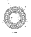
- a known rotary magnetic gear 100 comprises a first or inner rotor 102, a second or outer rotor 104 having a common axis of rotation with the first rotor 102, and a number of pole pieces 106 of ferromagnetic material supported between the rotors 102, 104.
- the first rotor 102 comprises a support 108 carrying a first set of permanent magnets 110, arranged with their north and south poles at their radially inner and outer ends, and orientated with alternating polarity so that each of the magnets 110 has its poles facing in the opposite direction to the magnets on either side of it.
- the first rotor 102 comprises eight permanent magnets, or four pole-pairs, arranged to produce a spatially varying magnetic field.
- the second rotor 104 comprises a support 112 carrying a second set of permanent magnets 114, again arranged with their poles facing radially inwards and outwards, and with alternating polarity.
- the second rotor 104 comprises 46 permanent magnets or 23 pole-pairs arranged to produce a spatially varying field.
- the first and second sets of permanent magnets therefore include different numbers of magnets. Accordingly, without any modulation of the magnetic fields they produce, there would be little or no useful magnetic coupling or interaction between the two sets of permanents magnets 110 and 114 such that rotation of one rotor would not cause rotation of the other rotor.
- the pole pieces 106 which are supported in a cylindrical non-magnetic support 116, are used to control the way in which the fields of the permanent magnets 110 and 114 interact.
- the pole pieces 106 modulate the magnetic fields of the permanent magnets 110 and 114 so that they interact to the extent that rotation of one rotor will induce rotation of the other rotor in a geared manner.
- the number of pole pieces is chosen to be equal to the sum of the number of pole-pairs of the two sets of permanent magnets. Rotation of the first rotor 102 at a speed ⁇ 1 will induce rotation of the second rotor 104 at a speed ⁇ 2 where ⁇ 1 > ⁇ 2 .
- the ratio between the speeds of rotation ⁇ 1 and ⁇ 2 i.e.
- the gearing ratio of the coupling is equal to the ratio between the numbers of pole pairs of the magnets 110 and 114 on the first and second rotors 102, 104.
- the gear can operate in reverse, so that rotation of the second rotor 104 will cause rotation of the first rotor at a higher speed.
- a magnetic gear 200 comprises three coaxial rotors: a cylindrical inner rotor 202 carrying a first set of magnets 210 providing a first set of magnetic pole pairs, a cylindrical outer rotor 204 carrying a second set of magnets 214 providing a second set of pole pairs, and a third cylindrical rotor 216 located radially between the inner and outer rotors 202, 204, which carries the set of pole pieces 206.
- the magnets 210, 214 and pole pieces 206 are spaced as in the coupling of Figure 1 .
- the inner rotor 202 is supported on an input shaft 220 so as to be rotatable therewith, and the outer rotor 204 is supported on an output shaft 222 so as to be rotatable therewith.
- the pole piece rotor 216 is rotatably supported on the input shaft 220 by means of a bearing 224.
- the third rotor 216 is therefore rotatable relative to, and independently of, the inner and outer rotors 202, 204.
- a drive motor 230 is drivingly connected by a mechanical transmission 231 to the pole piece rotor 216 so that it can rotate the pole piece rotor 216 at a speed which can be controlled and varied to control the gear ratio of the gear. If the drive motor 230 is switched off or held stationary, then the pole piece rotor 216 is held stationary and the coupling operates like the coupling of Figure 1 .
- the gear ratio between the inner rotor 202 and outer rotor 204 can be adjusted by adjusting the speed of the pole-piece rotor 216.
- the gear can operate in reverse, with the shaft 222 forming the input shaft, the outer rotor 204 forming the input rotor, the shaft 220 forming the output shaft, and the inner rotor 202 forming the output rotor.
- any one of the rotors can be used to control gear ratio between the other two rotors, and hence any two of the rotors can be selected as the input and output rotors with the third acting as the gear ratio control rotor.
- the spacing of the rotors, magnetic poles and pole pieces is the same as in the first embodiment, and corresponding parts are indicated by the same reference numerals increased by 100.
- the difference is that in this embodiment, while the outer rotor 304 is again directly connected to the output shaft 322, the pole-piece rotor 316 is connected by a mechanical transmission in the form of drive teeth 317 to the input shaft 320, and the inner rotor 302 is directly connected to the output shaft of the electric motor 330. Therefore in this embodiment the inner rotor 302 forms the gear ratio control rotor, and the pole piece rotor 316 and outer rotor 304 form the input and output rotors.
- the spacing of the rotors, magnetic poles and pole pieces is again the same as in the first embodiment, and corresponding parts are indicated by the same reference numerals as in Figure 5 again increased by 100.
- the inner rotor 402 and pole-piece rotor 416 form the input and output rotors and are connected to the input and output shafts 420, 422, and the outer rotor 404 is coupled by a mechanical transmission 431 to the motor 430 and forms the gear ratio control rotor.
- the inner rotor 502 with its associated set of magnets 510, and the pole-piece rotor 516 carrying the pole pieces 506 form the input and output rotors
- the outer rotor 504 forms the gear ratio control rotor, as in the embodiment of Figure 6 .
- the outer rotor 504 is driven by a permanent magnet electrical machine.
- the outer rotor 504 includes an inner array of magnets 514 which cooperate with the pole pieces 506 and the magnets on the inner rotor 502 to provide the gearing, and an outer array of magnets 515 which form part of the permanent magnet electrical machine.
- a stator 540 is provided radially outside the outer rotor 514, and comprises a series of coils 542 wound on ferromagnetic cores 544.
- the current flowing in these coils can be controlled to control the driving torque applied to the outer rotor 504 via the outer array of magnets 515. This enables the speed of rotation of the outer rotor 504 to be controlled, and hence the gear ratio of the gear to be varied and controlled.
- the outer magnet array 515 has a different number of poles than the inner magnet array 514. It is an advantage of having the two arrays that the gear and the electric motor can be tuned independently of each other. However, the outer magnet array 515 could have an identical number of poles to the inner array 514. In this case, it is possible to combine both magnet arrays into a single magnet array, which may be held in a non-magnetic holding structure
- a further embodiment of the invention comprises a wind turbine generator system.
- the system comprises a turbine rotor 650 which has a number of blades 652 arranged to be rotated by the wind at variable speed.
- the turbine rotor 650 is connected via a mechanical transmission 654 to the input rotor 602 of a variable gear ratio magnetic coupling 600 which corresponds to that of Figure 7 with corresponding parts indicated by the same reference numerals increased by 100.
- the output rotor 616, of the coupling which is the pole piece rotor, is connected to a constant speed electrical generator 656 which is directly connected to the three-phase electrical grid 658.
- the coils 642 of the electrical machine are connected to the electrical grid through a control system 660 which includes a power-electronics converter.
- the control system 660 is arranged to control the speed of the outer rotor 604, in order to change the gear ratio of the variable gear 600 so that the variable speed of the input rotor 602 is always matched to the constant speed of the output rotor 616.
- the torque which must be applied on the outer rotor 604 by the electrical machine 642, 615 is governed by the torque on the blades, and is always in an identical direction which does not depend on wind speed.
- the speed and direction at which the outer rotor 604 is rotated by the electrical machine 642,615 is varied as a function of the wind speed.
- the control system 660 is thus arranged to take power from the grid 658 to make the electrical machine operate as a motor when it drives the outer, gear ratio controlling, rotor 614 in the same direction to the torque, or to provide power to the grid to make the electrical machine operate as a generator when it drives the outer rotor 614 in the opposite direction to the torque.
- the electrical machine therefore acts as a motor/generator under the control of the control system 660.
- the control system includes speed sensors arranged to sense the speed of each of the rotors 602 and 604 to enable it to provide the required speed control.
- the required gear ratio between the speed of the blades and the speed of the main generator 656 is equal to the nominal gear ratio of the drive train, which results from the combination of the fixed gear and the variable gear with a stationary outer rotor 604.
- the motor/generator 642, 615 is controlled to apply a torque on the outer rotor 604 and to keep the outer rotor 604 stationary, and there is no power flow between the motor/generator and the variable gear.
- the required gear ratio between the speed of the blades 652 and the constant speed of the main generator 656 is greater than the nominal gear ratio of the drive train.
- the motor/generator 615/642 is operated to rotate the outer rotor 604 of the variable gear to adjust the overall gear ratio, while the direction of the torque that the motor/generator applies on the outer rotor 604 remains unchanged. Therefore, power is taken from the grid 658 into the electrical machine 615, 642, i.e. the electrical machine 615, 642 in the variable gear 600 operates as a motor. This power then flows through the main electrical generator 656 back into the grid 658. The power through the main electrical generator 656 is greater than the total generated power.
- the required gear ratio between the speed of the blades 652 and the constant speed of the main generator 656 is smaller than the nominal gear ratio of the drive train.
- the motor/generator 615/642 is operated to rotate the outer rotor 604 of the variable gear to adjust the overall gear ratio in a direction which is opposite to the direction of rotation at low wind speeds, while the direction of the torque that the motor/generator applies on the outer rotor 604 remains unchanged. Therefore, the electrical machine 615, 642 works as a generator. Part of the available wind power flows through the variable gear 600 and its electrical machine into the grid, and the remainder of the available power flows through the main electrical generator 656. The power through the main generator 656 is therefore smaller than the total generated power.
- the motor/generator 615, 642 works as a generator and therefore assists the main electrical generator, the main electrical generator 656 can be smaller and cheaper.
- This arrangement allows for a constant speed electrical generator 656 to be directly connected to the grid 658, whilst the blades 652 can operate at a speed that maximizes energy capture. Therefore there is no need for power electronics between the electrical generator 656 and the electrical grid 658.
- variable gear 600 The power needed to control the variable gear 600 depends on the wind speed, but is generally no more than 25% of the power which is generated by the entire turbine 650.
- the power electronics 660 in the entire system is therefore much smaller than would be required if no variable gear was used. Also, because most of the power does not go through power electronics, the efficiency is high.
- the motor/generator 642, 615 need not be connected to the grid through a controller 660, but can be connected to a separate external power supply.
- a controller 660 can be connected to a separate external power supply.
- Such an arrangement could for example be utilized in power generation systems which work in island operation, where the grid is absent at the start of the operation, such that, for example, an additional battery pack or a separate power source is required to operate the electrical machine 615, 642 at start-up.
- the electrical machine 615, 642 could be connected to a separate power supply in continuous operation.
- a further embodiment of the invention is also a wind turbine generator system similar to that of Figure 8 , with corresponding parts indicated by the same reference numerals increased by 100.
- the outer rotor 704 only has one set of magnets 714 and the outer rotor 704 is connected to the output shaft 722 by a variable coupling 760 which controls the speed of the outer rotor 704 dependent on the speed of the output shaft 722.
- the coupling 760 has at least one of its rotors 760a connected to the outer rotor 704 and one of its rotors 760b connected to the output shaft 722.
- the system further requires speed sensors to detect the speed of the output shaft or input shaft so as to control the variable coupling 760 appropriately and apply the correct feedback.
- om a is the speed of the rotor 760a of the coupling which is connected to the outer rotor 704 of the variable gear
- om b is the speed of the rotor 760b of the coupling which is connected to the output shaft 722
- k is a characteristic of the coupling.
- the coupling is further arranged so that the proportional constant k can be varied, such that the torque between the rotors can be varied for a given speed difference between the rotors 760a and 760b. For example, this could be achieved in an eddy current coupling by altering the mechanical airgap between the rotors 760a and 760b.
- the output rotor of the variable gear 716 is connected to the main generator 756 and is controlled to operate at a constant speed, while the input rotor 702 operates at a speed which is a function of the wind speed. Therefore, the speed of the outer rotor of the variable gear, and hence the difference of the speeds between the rotors 760a and 760b of the coupling, are dependent on the wind speed. Further, the torque which is required on the outer rotor 704 of the variable gear is governed by the torque on the blades 750, which is dependent on the wind speed.
- the control system aims to find a value k for each wind speed, for which the difference in speed between the rotors of the coupling 760a and 760b generates the required torque on the outer rotor of the variable gear.
- the generator 756 therefore runs at an approximately constant speed.
- the coupling 760 can be an eddy-current coupling with adjustable air-gap, or a hydrodynamic torque converter with adjustable vanes on the stator, for example. This coupling feeds back energy in order to keep the output rotor 716 at approximately constant speed.
- This system does not require the electrical machine and power electronics of the embodiment of Figure 8 to drive the outer rotor of the variable gear. Instead the coupling acts as a feedback mechanism, which reacts to a change in speed of the main generator by applying torque on the outer rotor of the variable gear.
- variable gear that is used in Figures 8 and 9 only shows one example of the integration of the invention within a power generation system. Any of the embodiments which are previously shown in Figures 3 to 7 or the embodiment shown in Figure 10 can be utilized in the system of Figure 8 .
- the diesel engine would be running at a constant speed, whilst the output shaft rotates at a speed which is a function of the speed of the vehicle.
- the arrangement would provide the advantage over a direct-drive system that the diesel engine can work at its most optimal constant speed, and only a fraction of the total output power needs to be controlled to provide a variable speed output.
- a further embodiment of the invention comprises a magnetic gear with the same basic topology as that of Figure 5 . Again, similar parts are indicated by the same reference numerals increased by 500 from those in Figure 5 .
- the outer rotor 804 is connected to one input/ouput shaft 822 and the pole piece rotor 816 is connected to the other input /output shaft 820, these two shafts 820, 822 extending out through opposite ends of an outer casing which forms a stator 840.
- the pole piece rotor 816 is in the form of a closed cylinder and the inner rotor 802 is rotatably supported on bearings inside the inner rotor.
- the inner rotor 802 therefore cannot be driven mechanically, but is driven magnetically by coils 842 wound on cores 844 on the stator 840. Because the spacing of the magnetic poles of the inner rotor 802 and stator coils 842 is several times greater than the spacing of the magnetic poles of the outer rotor 804 and the pole pieces, the coils can be used to drive the inner rotor 802 without significantly interfering with, or interference from, the outer rotor 804.
- the outer rotor 804 in this topology carries no back-iron, as this would prevent the flux from the inner magnets 810 from reaching the stator windings 842. Therefore, it is beneficial to arrange the outer magnets in a Halbach array.
- a downsized internal combustion (IC) engine 901 is connected to a rotor, in this case the inner rotor 902 of a continuously variable transmission (CVT) in the form of a variable ratio magnetic gear 900, whilst the other two rotors 904, 916 are each coupled to a motor/generator, MG1, and MG2 respectively. Both of the motor/generators MG1, MG2 are interfaced to a high-voltage battery pack 960 via a power electronic converter 962.
- CVT continuously variable transmission
- the first motor/generator MG1 is integrated within the variable gear 900 and is arranged to drive the outer rotor 904 of the variable gear.
- the output shaft 922 is coupled to the pole piece rotor 916 via an additional reduction gear unit 964.
- the second motor/generator is arranged to store energy from the IC engine in the battery pack 960 when the total power output of the IC engine is not being used, and to take power from the battery pack 960 to provide additional torque to the output shaft when the IC engine is not producing sufficient power for the needs of the vehicle.
- the drive-train becomes a transmission with a fixed gear-ratio g r .
- the required traction power at the output of the transmission is P d ( ⁇ d , T d )
- the corresponding torque and speed at the transmission output with the fixed gear-ratio are ( ⁇ s /g r , g r T s ). However, it is likely that they do not match the desired traction speed ⁇ d and torque T d .
- an arbitrary combination of traction torque and speed can be met within the available operating envelope of the ICE by independently controlling the speed of MG1 and the speed of MG2 such that the IC-engine always operates at its most efficient point. If the required traction power is different from that of the IC engine output a similar control strategy can be employed, with the battery being charged or discharged depending on whether the demanded power is less or greater than the IC-output.
- variable gear that is used in Figures 12 only shows one example of the integration of the invention within the drive train of a hybrid vehicle. Any of the embodiments which are previously shown in Figures 3 to 10 can be utilized in the system of Figure12 .
- each of the permanent magnets is a simple dipole with one north and one south pole
- any arrangement of pole pairs can be provided by a number of different arrangements of magnets, i.e. blocks of magnetized material.
- more than one pole pair can be provided by a single magnetized block.
- the three rotors are all cylindrical, spaced radially from each other. However it will be appreciated that they can be planar and spaced along their common axis of rotation, with the magnets providing flux in an axial direction. Further, the embodiments can also be arranged to operate in a linear manner, in which one translator is used to control the gear ratio between the two other translators.
Abstract
Description
- The present invention relates to magnetic gears, and in particular to the control of the gear ratio of magnetic gears.
- Magnetic gears are known in which input and output rotors are provided with respective sets of magnetic pole pairs at different spacings, and a set of ferromagnetic pole pieces is arranged between the input and output rotors to modulate the magnetic field and allow the input rotor to drive the output rotor with a gear ratio which depends on the ratio of the spacings of the two sets of magnetic poles and the spacing of the pole pieces.
- The present invention provides a magnetic gear comprising: a first movable member having a first set of magnetic poles, a second movable member having a second set of magnetic poles, and a third movable member having a set of pole pieces; wherein the first and second members have magnetic poles at different spacings and the pole pieces are arranged to modulate the magnetic field acting between the magnetic poles, and control means arranged to control rotation of one of the members so as to vary the gear ratio between the other two members
- The movable members may comprise rotors or, in a linear system, translators.
- The present invention further provides a power generation system comprising an input member, a generator, and a magnetic gear coupling the input member to the generator, wherein the magnetic gear is a gear according to the invention.
- The present invention further provides a power train system comprising a prime mover, a load, and a magnetic gear coupling the prime mover to the load, wherein the magnetic gear is a gear according to the invention.
- The present invention further provides a power train system comprising an engine, an output member, a magnetic gear connecting the engine to the output member, an energy storage system, and control means arranged to control the flow of power from the output member to the energy storage system and from the energy storage system to the output member, wherein the magnetic gear comprises a first rotor having a first set of magnetic poles, a second rotor having a second set of magnetic poles, and a third rotor having a set of pole pieces, the first and second rotors have different numbers of magnetic poles, the pole pieces are arranged to modulate the magnetic field acting between the magnetic poles, and the control means is arranged to control rotation of one of the rotors so as to vary the gear ratio between the other two rotors.
-
-
Figure 1 is a schematic section through a known rotary magnetic gearing system; -
Figure 2 is a longitudinal section through the gearing system ofFigure 1 ; -
Figure 3 is a cross sectional view of a drive coupling according to a first embodiment of the invention; -
Figure 4 is a longitudinal section through the drive coupling ofFigure 3 ; -
Figure 5 is a longitudinal section through a drive coupling according to a second embodiment of the invention; -
Figure 6 is a longitudinal section through a drive coupling according to a further embodiment of the invention; -
Figure 7 is a cross section through a drive coupling according to a further embodiment of the invention; -
Figure 8 is a schematic longitudinal section through a power generation system according to a further embodiment of the invention; -
Figure 9 is a schematic longitudinal section through a power generation system according to a further embodiment of the invention; -
Figure 10 is a schematic cross section through a drive coupling according to a further embodiment of the invention; -
Figure 11 is a schematic longitudinal section through the drive coupling ofFigure 10 ; -
Figure 12 is a schematic longitudinal section through a vehicle drive train according to a further embodiment of the invention; and -
Figure 13 is a functional diagram of the drive train ofFigure 12 . - Referring to
Figures 1 and2 , a known rotarymagnetic gear 100 comprises a first orinner rotor 102, a second orouter rotor 104 having a common axis of rotation with thefirst rotor 102, and a number ofpole pieces 106 of ferromagnetic material supported between therotors first rotor 102 comprises asupport 108 carrying a first set ofpermanent magnets 110, arranged with their north and south poles at their radially inner and outer ends, and orientated with alternating polarity so that each of themagnets 110 has its poles facing in the opposite direction to the magnets on either side of it. In this embodiment, thefirst rotor 102 comprises eight permanent magnets, or four pole-pairs, arranged to produce a spatially varying magnetic field. Thesecond rotor 104 comprises asupport 112 carrying a second set ofpermanent magnets 114, again arranged with their poles facing radially inwards and outwards, and with alternating polarity. Thesecond rotor 104 comprises 46 permanent magnets or 23 pole-pairs arranged to produce a spatially varying field. The first and second sets of permanent magnets therefore include different numbers of magnets. Accordingly, without any modulation of the magnetic fields they produce, there would be little or no useful magnetic coupling or interaction between the two sets ofpermanents magnets - The
pole pieces 106, which are supported in a cylindricalnon-magnetic support 116, are used to control the way in which the fields of thepermanent magnets pole pieces 106 modulate the magnetic fields of thepermanent magnets first rotor 102 at a speed ω1 will induce rotation of thesecond rotor 104 at a speed ω2 where ω1 > ω2. The ratio between the speeds of rotation ω1 and ω2, i.e. the gearing ratio of the coupling, is equal to the ratio between the numbers of pole pairs of themagnets second rotors second rotor 104 will cause rotation of the first rotor at a higher speed. - Referring to
Figures 3 and4 , in a first embodiment of the invention amagnetic gear 200 comprises three coaxial rotors: a cylindricalinner rotor 202 carrying a first set ofmagnets 210 providing a first set of magnetic pole pairs, a cylindricalouter rotor 204 carrying a second set ofmagnets 214 providing a second set of pole pairs, and a thirdcylindrical rotor 216 located radially between the inner andouter rotors pole pieces 206. Themagnets pole pieces 206 are spaced as in the coupling ofFigure 1 . Referring toFigure 4 , theinner rotor 202 is supported on aninput shaft 220 so as to be rotatable therewith, and theouter rotor 204 is supported on anoutput shaft 222 so as to be rotatable therewith. Thepole piece rotor 216 is rotatably supported on theinput shaft 220 by means of abearing 224. Thethird rotor 216 is therefore rotatable relative to, and independently of, the inner andouter rotors drive motor 230 is drivingly connected by amechanical transmission 231 to thepole piece rotor 216 so that it can rotate thepole piece rotor 216 at a speed which can be controlled and varied to control the gear ratio of the gear. If thedrive motor 230 is switched off or held stationary, then thepole piece rotor 216 is held stationary and the coupling operates like the coupling ofFigure 1 . - The governing equation of speeds in the
magnetic gear 200 is:
With ωi, Pi the speed and number of magnetic pole-pairs in theinner rotor 202
ω 0, P0 the speed and number of magnetic pole-pairs in theouter rotor 204 ωp, np the speed of the pole-piece rotor 216 and the number of pole-pieces 206. - When pole-
pieces 206 are held stationary (ωp = 0), the relationship between the speeds of theinner rotor 202 andouter rotor 204 is
which results in a fixed gear-ratio as in the prior art gear ofFigure 1 . - When the speed of the pole-
pieces 206 is controlled and variable over a range of speeds, the relationship between the speeds of the inner and outer rotors and the pole piece rotor is
Hence, the gear ratio between theinner rotor 202 andouter rotor 204 can be adjusted by adjusting the speed of the pole-piece rotor 216. - It will be appreciated that the gear can operate in reverse, with the
shaft 222 forming the input shaft, theouter rotor 204 forming the input rotor, theshaft 220 forming the output shaft, and theinner rotor 202 forming the output rotor. Indeed, as can be seen from equation (1), any one of the rotors can be used to control gear ratio between the other two rotors, and hence any two of the rotors can be selected as the input and output rotors with the third acting as the gear ratio control rotor. - Referring to
Figures 5 , in a second embodiment of the invention the spacing of the rotors, magnetic poles and pole pieces is the same as in the first embodiment, and corresponding parts are indicated by the same reference numerals increased by 100. The difference is that in this embodiment, while theouter rotor 304 is again directly connected to theoutput shaft 322, the pole-piece rotor 316 is connected by a mechanical transmission in the form ofdrive teeth 317 to theinput shaft 320, and theinner rotor 302 is directly connected to the output shaft of theelectric motor 330. Therefore in this embodiment theinner rotor 302 forms the gear ratio control rotor, and thepole piece rotor 316 andouter rotor 304 form the input and output rotors. - Referring to
Figure 6 , in a third embodiment of the invention, the spacing of the rotors, magnetic poles and pole pieces is again the same as in the first embodiment, and corresponding parts are indicated by the same reference numerals as inFigure 5 again increased by 100. In this embodiment theinner rotor 402 and pole-piece rotor 416 form the input and output rotors and are connected to the input andoutput shafts outer rotor 404 is coupled by amechanical transmission 431 to themotor 430 and forms the gear ratio control rotor. - The use of an electric motor and a mechanical transmission in the embodiments of
Figures 4 to 6 are examples of how the speed of the gear ratio control rotor can be controlled, and it will be appreciated that other methods can be used. - Referring to
Figure 7 , in a fourth embodiment of the invention, theinner rotor 502 with its associated set ofmagnets 510, and the pole-piece rotor 516 carrying thepole pieces 506 form the input and output rotors, and theouter rotor 504 forms the gear ratio control rotor, as in the embodiment ofFigure 6 . However, in this case theouter rotor 504 is driven by a permanent magnet electrical machine. To this end, theouter rotor 504 includes an inner array ofmagnets 514 which cooperate with thepole pieces 506 and the magnets on theinner rotor 502 to provide the gearing, and an outer array ofmagnets 515 which form part of the permanent magnet electrical machine. Astator 540 is provided radially outside theouter rotor 514, and comprises a series ofcoils 542 wound onferromagnetic cores 544. The current flowing in these coils can be controlled to control the driving torque applied to theouter rotor 504 via the outer array ofmagnets 515. This enables the speed of rotation of theouter rotor 504 to be controlled, and hence the gear ratio of the gear to be varied and controlled. - In this embodiment the
outer magnet array 515 has a different number of poles than theinner magnet array 514. It is an advantage of having the two arrays that the gear and the electric motor can be tuned independently of each other. However, theouter magnet array 515 could have an identical number of poles to theinner array 514. In this case, it is possible to combine both magnet arrays into a single magnet array, which may be held in a non-magnetic holding structure - Referring to
Figure 8 a further embodiment of the invention comprises a wind turbine generator system. The system comprises aturbine rotor 650 which has a number ofblades 652 arranged to be rotated by the wind at variable speed. Theturbine rotor 650 is connected via amechanical transmission 654 to theinput rotor 602 of a variable gear ratiomagnetic coupling 600 which corresponds to that ofFigure 7 with corresponding parts indicated by the same reference numerals increased by 100. Theoutput rotor 616, of the coupling, which is the pole piece rotor, is connected to a constant speedelectrical generator 656 which is directly connected to the three-phaseelectrical grid 658. Thecoils 642 of the electrical machine are connected to the electrical grid through acontrol system 660 which includes a power-electronics converter. Thecontrol system 660 is arranged to control the speed of theouter rotor 604, in order to change the gear ratio of thevariable gear 600 so that the variable speed of theinput rotor 602 is always matched to the constant speed of theoutput rotor 616. The torque which must be applied on theouter rotor 604 by theelectrical machine outer rotor 604 is rotated by the electrical machine 642,615 is varied as a function of the wind speed. Thecontrol system 660 is thus arranged to take power from thegrid 658 to make the electrical machine operate as a motor when it drives the outer, gear ratio controlling,rotor 614 in the same direction to the torque, or to provide power to the grid to make the electrical machine operate as a generator when it drives theouter rotor 614 in the opposite direction to the torque. The electrical machine therefore acts as a motor/generator under the control of thecontrol system 660. The control system includes speed sensors arranged to sense the speed of each of therotors - At the nominal wind speed of the wind turbine, the required gear ratio between the speed of the blades and the speed of the
main generator 656 is equal to the nominal gear ratio of the drive train, which results from the combination of the fixed gear and the variable gear with a stationaryouter rotor 604. At this wind speed, the motor/generator outer rotor 604 and to keep theouter rotor 604 stationary, and there is no power flow between the motor/generator and the variable gear. - At low wind speeds, the required gear ratio between the speed of the
blades 652 and the constant speed of themain generator 656 is greater than the nominal gear ratio of the drive train. Hence, the motor/generator 615/642 is operated to rotate theouter rotor 604 of the variable gear to adjust the overall gear ratio, while the direction of the torque that the motor/generator applies on theouter rotor 604 remains unchanged. Therefore, power is taken from thegrid 658 into theelectrical machine electrical machine variable gear 600 operates as a motor. This power then flows through the mainelectrical generator 656 back into thegrid 658. The power through the mainelectrical generator 656 is greater than the total generated power. At high wind speeds, the required gear ratio between the speed of theblades 652 and the constant speed of themain generator 656 is smaller than the nominal gear ratio of the drive train. The motor/generator 615/642 is operated to rotate theouter rotor 604 of the variable gear to adjust the overall gear ratio in a direction which is opposite to the direction of rotation at low wind speeds, while the direction of the torque that the motor/generator applies on theouter rotor 604 remains unchanged. Therefore, theelectrical machine variable gear 600 and its electrical machine into the grid, and the remainder of the available power flows through the mainelectrical generator 656. The power through themain generator 656 is therefore smaller than the total generated power. - Because at peak power (high wind speed), the motor/
generator electrical generator 656 can be smaller and cheaper. - This arrangement allows for a constant speed
electrical generator 656 to be directly connected to thegrid 658, whilst theblades 652 can operate at a speed that maximizes energy capture. Therefore there is no need for power electronics between theelectrical generator 656 and theelectrical grid 658. - The power needed to control the
variable gear 600 depends on the wind speed, but is generally no more than 25% of the power which is generated by theentire turbine 650. Thepower electronics 660 in the entire system is therefore much smaller than would be required if no variable gear was used. Also, because most of the power does not go through power electronics, the efficiency is high. - It will be understood by those skilled in the art that the motor/
generator controller 660, but can be connected to a separate external power supply. Such an arrangement could for example be utilized in power generation systems which work in island operation, where the grid is absent at the start of the operation, such that, for example, an additional battery pack or a separate power source is required to operate theelectrical machine electrical machine - Referring to
Figure 9 , a further embodiment of the invention is also a wind turbine generator system similar to that ofFigure 8 , with corresponding parts indicated by the same reference numerals increased by 100. In this case, theouter rotor 704 only has one set ofmagnets 714 and theouter rotor 704 is connected to theoutput shaft 722 by avariable coupling 760 which controls the speed of theouter rotor 704 dependent on the speed of theoutput shaft 722. Thecoupling 760 has at least one of itsrotors 760a connected to theouter rotor 704 and one of itsrotors 760b connected to theoutput shaft 722. The system further requires speed sensors to detect the speed of the output shaft or input shaft so as to control thevariable coupling 760 appropriately and apply the correct feedback. - The coupling is arranged so that a difference in speed between its two
rotors 
where
oma is the speed of therotor 760a of the coupling which is connected to theouter rotor 704 of the variable gear,
omb is the speed of therotor 760b of the coupling which is connected to theoutput shaft 722, and
k is a characteristic of the coupling. - The coupling is further arranged so that the proportional constant k can be varied, such that the torque between the rotors can be varied for a given speed difference between the
rotors rotors - The output rotor of the
variable gear 716 is connected to themain generator 756 and is controlled to operate at a constant speed, while theinput rotor 702 operates at a speed which is a function of the wind speed. Therefore, the speed of the outer rotor of the variable gear, and hence the difference of the speeds between therotors outer rotor 704 of the variable gear is governed by the torque on theblades 750, which is dependent on the wind speed. - The control system aims to find a value k for each wind speed, for which the difference in speed between the rotors of the
coupling generator 756 therefore runs at an approximately constant speed. Thecoupling 760 can be an eddy-current coupling with adjustable air-gap, or a hydrodynamic torque converter with adjustable vanes on the stator, for example. This coupling feeds back energy in order to keep theoutput rotor 716 at approximately constant speed. - This system does not require the electrical machine and power electronics of the embodiment of
Figure 8 to drive the outer rotor of the variable gear. Instead the coupling acts as a feedback mechanism, which reacts to a change in speed of the main generator by applying torque on the outer rotor of the variable gear. - The embodiment of the variable gear that is used in
Figures 8 and 9 only shows one example of the integration of the invention within a power generation system. Any of the embodiments which are previously shown inFigures 3 to 7 or the embodiment shown inFigure 10 can be utilized in the system ofFigure 8 . - It will be understood by those skilled in the art that, whereas the embodiments which are shown in
Figures 8 and 9 are described with reference to power generation from wind energy, other sources of power may be used to apply torque on the main input shaft to generate power, such as fossil fuels in internal and external combustion engines, water energy in wave generators, thermal energy, etc. It will further be understood by those skilled in the art that the embodiment is not limited to power generation, but can be used in any power transmission system where the speed of rotation of the driven member must be de-coupled of the speed of rotation of the driving member. For example, the drive train of a locomotive or a ship which is powered by a diesel engine could employ an arrangement such as shown inFigure 8 or 9 . In this application, the diesel engine would be running at a constant speed, whilst the output shaft rotates at a speed which is a function of the speed of the vehicle. The arrangement would provide the advantage over a direct-drive system that the diesel engine can work at its most optimal constant speed, and only a fraction of the total output power needs to be controlled to provide a variable speed output. - Referring to
Figures 10 and 11 , a further embodiment of the invention comprises a magnetic gear with the same basic topology as that ofFigure 5 . Again, similar parts are indicated by the same reference numerals increased by 500 from those inFigure 5 . Theouter rotor 804 is connected to one input/ouput shaft 822 and thepole piece rotor 816 is connected to the other input /output shaft 820, these twoshafts stator 840. Thepole piece rotor 816 is in the form of a closed cylinder and theinner rotor 802 is rotatably supported on bearings inside the inner rotor. Theinner rotor 802 therefore cannot be driven mechanically, but is driven magnetically bycoils 842 wound oncores 844 on thestator 840. Because the spacing of the magnetic poles of theinner rotor 802 and stator coils 842 is several times greater than the spacing of the magnetic poles of theouter rotor 804 and the pole pieces, the coils can be used to drive theinner rotor 802 without significantly interfering with, or interference from, theouter rotor 804. Theouter rotor 804 in this topology carries no back-iron, as this would prevent the flux from theinner magnets 810 from reaching thestator windings 842. Therefore, it is beneficial to arrange the outer magnets in a Halbach array. - Referring to
Figures 12 and 13 , in a further embodiment of the invention a downsized internal combustion (IC)engine 901 is connected to a rotor, in this case theinner rotor 902 of a continuously variable transmission (CVT) in the form of a variable ratiomagnetic gear 900, whilst the other tworotors voltage battery pack 960 via a powerelectronic converter 962. - The first motor/generator MG1 is integrated within the
variable gear 900 and is arranged to drive theouter rotor 904 of the variable gear. Theoutput shaft 922 is coupled to thepole piece rotor 916 via an additionalreduction gear unit 964. The second motor/generator is arranged to store energy from the IC engine in thebattery pack 960 when the total power output of the IC engine is not being used, and to take power from thebattery pack 960 to provide additional torque to the output shaft when the IC engine is not producing sufficient power for the needs of the vehicle. - If MG1 and MG2 are not excited, the drive-train becomes a transmission with a fixed gear-ratio gr. If the required traction power at the output of the transmission is Pd (Ωd, Td), ideally the IC engine should operate at its most fuel-efficient point (Ωs, Ts), such that Ωs Ts = Pd. The corresponding torque and speed at the transmission output with the fixed gear-ratio are (Ωs/gr, grTs). However, it is likely that they do not match the desired traction speed Ωd and torque Td. However, if Td > Tsgr, then Ωd < Ωs/gr, and the torque deficit can be met by operating MG2 as a motor, taking power from the energy storage battery. In order to obtain the desired traction speed without varyng the IC engine point, operation of MG1 can change the gear ratio such that the resultant speed of the output drive matches Ωd. This requires MG1 to operate as a generator, supplying electrical energy to the battery. If the loss in the electrical system is negligible, then the power taken by MG2 is equal to the power supplied by MG1. Hence the net power is zero, and the battery is neither charged nor discharged. Thus, an arbitrary combination of traction torque and speed can be met within the available operating envelope of the ICE by independently controlling the speed of MG1 and the speed of MG2 such that the IC-engine always operates at its most efficient point. If the required traction power is different from that of the IC engine output a similar control strategy can be employed, with the battery being charged or discharged depending on whether the demanded power is less or greater than the IC-output.
- The embodiment of the variable gear that is used in
Figures 12 only shows one example of the integration of the invention within the drive train of a hybrid vehicle. Any of the embodiments which are previously shown inFigures 3 to 10 can be utilized in the system ofFigure12 . - While in each of the embodiments described above, each of the permanent magnets is a simple dipole with one north and one south pole, it will be appreciate that, while the positioning of the magnetic poles is critical to the operation of each embodiment, any arrangement of pole pairs can be provided by a number of different arrangements of magnets, i.e. blocks of magnetized material. For example more than one pole pair can be provided by a single magnetized block.
- In the embodiments described above, the three rotors are all cylindrical, spaced radially from each other. However it will be appreciated that they can be planar and spaced along their common axis of rotation, with the magnets providing flux in an axial direction. Further, the embodiments can also be arranged to operate in a linear manner, in which one translator is used to control the gear ratio between the two other translators.
-
- Embodiment 1. A magnetic gear comprising: a first movable member having a first set of magnetic poles, a second movable member having a second set of magnetic poles, and a third movable member having a set of pole pieces; wherein the first and second members have magnetic poles at different spacings and the pole pieces are arranged to modulate the magnetic field acting between the magnetic poles, and control means arranged to control rotation of one of the members so as to vary the gear ratio between the other two members.
- Embodiment 2. A magnetic gear according to embodiment 1 wherein the control means comprises an electrical machine.
- Embodiment 3. A magnetic gear according to embodiment 2 wherein the electrical machine comprises a plurality of coils and a plurality of drive magnets having a set of magnetic poles.
- Embodiment 4. A magnetic gear according to embodiment 3 wherein the drive magnets are mounted on one of the members.
- Embodiment 5. A magnetic gear according to embodiment 4 wherein the drive magnets are mounted on one of the first and second members.
- Embodiment 6. A magnetic gear according to embodiment 5 wherein the magnetic poles of the drive magnets comprise the first or second sets of magnetic poles.
- Embodiment 7. A magnetic gear according to embodiment 5 wherein the magnetic poles of the drive magnets comprise a third set of magnetic poles separate from the first and second sets of magnetic poles.
- Embodiment 8. A magnetic gear according to embodiment 7 wherein the third set of magnetic poles has a different number of poles from the other set of magnetic poles on the same member.
- Embodiment 9. A magnetic gear according to any of embodiments 2 to 8 wherein the electric machine can act as a motor and as a generator.
- Embodiment 10. A magnetic gear according to embodiment 9 wherein the control means is arranged to control the electric machine so as to control the speed of said one of the members by applying a braking torque when the machine is acting as a generator and a driving torque when the machine as acting as a motor.
- Embodiment 11. A magnetic gear according to any foregoing embodiment wherein the control means is arranged to control the gear ratio of the gear so as to control the speed of one of the members to a target value.
- Embodiment 12. A magnetic gear according to embodiment 11 wherein the target value is a constant value.
- Embodiment 13. A power generation system comprising an input member, a generator, and a magnetic gear coupling the input member to the generator, wherein the magnetic gear is a gear according to any foregoing claim.
- Embodiment 14. A power generation system according to embodiment 13 wherein the generator is connected to an electricity supply, and the control means is operable in a first mode in which it is arranged to take power from the supply to control the gear ratio, and a second mode in which it is arranged to control power transmitted from the input member to the supply to control the gear ratio.
- Embodiment 15. A power generation system according to embodiment 14 wherein the control means is arranged to control the speed of the generator so as to keep it substantially constant.
- Embodiment 16. A power generation system according to embodiment 13 wherein the generator is connected to an electricity supply and the control means utilizes a feedback mechanism between the output and the rotor of the variable gear which is controlled to vary the gear ratio, where the feedback mechanism imparts a controllable torque between the components to which it is connected so as to control their rotational speeds.
- Embodiment 17. A power train system comprising a prime mover, a load, and a magnetic gear coupling the prime mover to the load, wherein the magnetic gear is a gear according to any of the claims 1 to 12.
- Embodiment 18. A power train system according to embodiment 17 wherein the control means is operable in a first mode in which it is arranged to take power from a power supply to control the gear ratio, and a second mode in which it is arranged to control power transmitted from the input member to a power supply to control the gear ratio.
- Embodiment 19. A power train system according to embodiment 18 wherein the control means is arranged to control the speed of the load when the speed of the prime-mover is substantially constant.
- Embodiment 20. A power train system according to embodiment 17 wherein a feedback mechanism is used between the shaft of the magnetic gear which speed is to be controlled and the rotor of the magnetic gear which is used to control the gear ratio, where the feedback mechanism imparts a controllable torque between the components to which it is connected so as to control their rotational speeds.
- Embodiment 21. A power train system comprising an engine, an output member, a magnetic gear connecting the engine to the output member, an energy storage system, and control means arranged to control the flow of power, wherein the magnetic gear comprises a first rotor having a first set of magnetic poles, a second rotor having a second set of magnetic poles, and a third rotor having a set of pole pieces, the first and second rotors have different numbers of magnetic poles, the pole pieces are arranged to modulate the magnetic field acting between the magnetic poles, and the control means is arranged to control rotation of one of the rotors so as to vary the gear ratio between the other two rotors.
- Embodiment 22. A power train system according to embodiment 21 wherein the control means includes a power distribution motor generator arranged to transmit power from the output member to the energy storage system and from the energy storage system to the output member.
- Embodiment 23. A power train system according to embodiment 21 or embodiment 22 wherein the control means includes a gear control motor generator operable in a first mode in which it is arranged to take power from the energy storage system to control the gear ratio, and a second mode in which it is arranged to control power transmitted from the input member to the energy storage system to control the gear ratio.
Claims (10)
- A power train system comprising an engine, an output member, a magnetic gear connecting the engine to the output member, an energy storage system, and control means arranged to control the flow of power from the engine to the energy storage system or from the energy storage system to the output member if a required power at the output member is different from a power at the engine, wherein the magnetic gear comprises a first rotor having a first set of magnetic poles, a second rotor having a second set of magnetic poles, and a third rotor having a set of pole pieces, the first and second rotors have different numbers of magnetic poles, the pole pieces are arranged to modulate the magnetic field acting between the magnetic poles, and the control means is arranged to control rotation of one of the rotors so as to vary the gear ratio between the other two rotors.
- A power train system according to claim 1 wherein the control means includes a power distribution motor generator arranged to transmit power from the engine to the energy storage system and from the energy storage system to the output member.
- A power train system according to claim 1 or 2 wherein the control means includes a gear control motor generator operable in a first mode in which it is arranged to take power from the energy storage system to control the gear ratio, and a second mode in which it is arranged to control power transmitted from the engine to the energy storage system to control the gear ratio.
- A power train system as claimed in claim 1 wherein the engine is connected to the first rotor, in this case an inner rotor of the magnetic gear, whilst the other two rotors, the second and third rotors, are each coupled to a motor/generator, MG1 and MG2 respectively.
- A power train system as claimed in claim 4, wherein both of the motor/generators MG1, MG2 are interfaced to an energy storage system via a power electronic converter.
- A power train system as claimed in claim 5, wherein the motor/generator MG1 is integrated with the magnetic gear and is arranged to drive an outer rotor, in this case the second rotor, of the magnetic gear.
- A power train system as claimed in any preceding claim, wherein an output shaft is coupled to the third rotor via an additional reduction gear unit.
- A power train system as claimed in claim 7, when dependent on claim 4, wherein the motor/generator MG2 is arranged to permit the storage of energy from the engine in the energy storage system when the total power output of the engine is not being used, and to take power from the energy storage system to provide additional torque to the output shaft when the engine is not producing sufficient power for the needs of a vehicle.
- A power train system as claimed in claim 1 wherein the engine is connected to the third rotor, the output member is connected to the first rotor, and the second rotor is used to vary the gear ratio between the third rotor and the first rotor.
- A hybrid vehicle comprising a power train system as claimed in any proceeding claim.
Applications Claiming Priority (3)
| Application Number | Priority Date | Filing Date | Title |
|---|---|---|---|
| GB0803119.7A GB2457682B (en) | 2008-02-21 | 2008-02-21 | Variable magnetic gears |
| EP12165375.2A EP2497974A3 (en) | 2008-02-21 | 2009-02-20 | Variable magnetic gears |
| EP09712378A EP2255107B1 (en) | 2008-02-21 | 2009-02-20 | Variable magnetic gears |
Related Parent Applications (4)
| Application Number | Title | Priority Date | Filing Date |
|---|---|---|---|
| EP12165375.2A Division EP2497974A3 (en) | 2008-02-21 | 2009-02-20 | Variable magnetic gears |
| EP09712378.0 Division | 2009-02-20 | ||
| EP09712378A Division EP2255107B1 (en) | 2008-02-21 | 2009-02-20 | Variable magnetic gears |
| EP12165375.2 Division | 2012-04-24 |
Publications (2)
| Publication Number | Publication Date |
|---|---|
| EP2644946A1 true EP2644946A1 (en) | 2013-10-02 |
| EP2644946B1 EP2644946B1 (en) | 2015-01-07 |
Family
ID=39272020
Family Applications (4)
| Application Number | Title | Priority Date | Filing Date |
|---|---|---|---|
| EP13160951.3A Active EP2644946B1 (en) | 2008-02-21 | 2009-02-20 | Variable magnetic gears |
| EP12165377.8A Active EP2481953B1 (en) | 2008-02-21 | 2009-02-20 | Variable magnetic gears |
| EP12165375.2A Withdrawn EP2497974A3 (en) | 2008-02-21 | 2009-02-20 | Variable magnetic gears |
| EP09712378A Active EP2255107B1 (en) | 2008-02-21 | 2009-02-20 | Variable magnetic gears |
Family Applications After (3)
| Application Number | Title | Priority Date | Filing Date |
|---|---|---|---|
| EP12165377.8A Active EP2481953B1 (en) | 2008-02-21 | 2009-02-20 | Variable magnetic gears |
| EP12165375.2A Withdrawn EP2497974A3 (en) | 2008-02-21 | 2009-02-20 | Variable magnetic gears |
| EP09712378A Active EP2255107B1 (en) | 2008-02-21 | 2009-02-20 | Variable magnetic gears |
Country Status (8)
| Country | Link |
|---|---|
| US (1) | US9013081B2 (en) |
| EP (4) | EP2644946B1 (en) |
| CN (2) | CN102016358B (en) |
| AT (1) | ATE555331T1 (en) |
| DK (1) | DK2481953T3 (en) |
| ES (3) | ES2389818T3 (en) |
| GB (1) | GB2457682B (en) |
| WO (1) | WO2009103993A1 (en) |
Cited By (4)
| Publication number | Priority date | Publication date | Assignee | Title |
|---|---|---|---|---|
| WO2016198858A1 (en) * | 2015-06-08 | 2016-12-15 | Elumotion Limited | Rotary actuator |
| EP3168968A1 (en) * | 2015-11-16 | 2017-05-17 | Rolls-Royce plc | Variable gear ratio electrical machine |
| DE102016121049B3 (en) * | 2016-11-04 | 2017-12-28 | GEORGI KOBOLD GmbH & Co. KG | Multi-stage magnetic gearbox |
| DE102018202837A1 (en) * | 2018-02-26 | 2019-08-29 | Audi Ag | Drive device for a motor vehicle |
Families Citing this family (108)
| Publication number | Priority date | Publication date | Assignee | Title |
|---|---|---|---|---|
| GB2457226B (en) * | 2008-01-11 | 2013-01-09 | Magnomatics Ltd | Drives for sealed systems |
| GB0810097D0 (en) | 2008-06-03 | 2008-07-09 | Magnomatics Ltd | Magnetic gear |
| WO2010082893A1 (en) * | 2009-01-15 | 2010-07-22 | Volvo Technology Corporation | Electromagnetic, continuously variable transmission power split turbo compound and engine and vehicle comprising such a turbo compound |
| FI20095213A0 (en) * | 2009-03-04 | 2009-03-04 | Prizztech Oy | Method and apparatus for induction heating |
| GB0905345D0 (en) | 2009-03-27 | 2009-05-13 | Ricardo Uk Ltd | A flywheel |
| GB0905344D0 (en) | 2009-03-27 | 2009-05-13 | Ricardo Uk Ltd | A flywheel |
| GB0905343D0 (en) | 2009-03-27 | 2009-05-13 | Ricardo Uk Ltd | A flywheel |
| GB0910224D0 (en) * | 2009-06-12 | 2009-07-29 | Univ Strathclyde | Magnetic gearbox |
| WO2011036552A1 (en) * | 2009-09-28 | 2011-03-31 | Stellenbosch University | Magnetic gear |
| GB0920148D0 (en) * | 2009-11-17 | 2009-12-30 | Magnomatics Ltd | Magnetically geared machine for marine generation |
| US20120293031A1 (en) | 2009-11-17 | 2012-11-22 | Ricardo Uk Limited | Coupler |
| EP2526611B1 (en) | 2010-01-19 | 2018-11-07 | Rolls-Royce plc | Magnetic gear arrangement |
| EP2390994A1 (en) | 2010-05-26 | 2011-11-30 | Delphi Technologies, Inc. | Magnetic gear and power split transmission using such |
| KR101205329B1 (en) * | 2010-06-11 | 2012-11-28 | 신익 | Wind Power Generator Having Triple Rotors Integrated System |
| CN102947565B (en) * | 2010-06-22 | 2015-04-15 | 沃尔沃拉斯特瓦格纳公司 | A turbo compound transmission and a method for controlling a turbo compound transmission |
| JP5408355B2 (en) * | 2010-07-29 | 2014-02-05 | 日立金属株式会社 | Magnetic gear device and holding member |
| US20120098374A1 (en) * | 2010-10-25 | 2012-04-26 | Alvaro Jorge Mari Curbelo | Variable-speed magnetic coupling and method for control |
| GB201019473D0 (en) | 2010-11-17 | 2010-12-29 | Ricardo Uk Ltd | An improved coupler |
| CN102563004B (en) * | 2010-12-15 | 2014-09-24 | 江建中 | Magnetic gear with novel magnetic-field regulating ring |
| US8319365B2 (en) * | 2010-12-17 | 2012-11-27 | General Electric Company | System and method to provide constant speed mechanical output in a machine |
| JP5286373B2 (en) * | 2011-01-28 | 2013-09-11 | 株式会社日立製作所 | Magnetic gear |
| GB201101678D0 (en) | 2011-02-01 | 2011-03-16 | Rolls Royce Plc | A cooling arrangement for a magnetic gearbox |
| CN103370561B (en) | 2011-02-21 | 2016-04-27 | 株式会社日立制作所 | Magnetic gear mechanism |
| TW201240847A (en) * | 2011-04-15 | 2012-10-16 | Yu-Chi Wang | Motor generator apparatus for vehicles |
| GB201106768D0 (en) | 2011-04-20 | 2011-06-01 | Ricardo Uk Ltd | An energy storage system |
| GB2490149A (en) | 2011-04-20 | 2012-10-24 | Corac Group Plc | Magnetic gearbox with gas bearings |
| CN102808919A (en) * | 2011-05-30 | 2012-12-05 | 余虹锦 | Magnetism transmission gear pair of novel transverse magnetic field |
| US9337708B2 (en) * | 2011-06-27 | 2016-05-10 | Hitachi, Ltd. | Magnetic gear-type electric rotating machine |
| KR20140013087A (en) * | 2011-07-15 | 2014-02-04 | 히타치 긴조쿠 가부시키가이샤 | Magnetic gear device |
| US9853532B2 (en) | 2011-07-22 | 2017-12-26 | Regal Beloit America, Inc. | Magnetic transmission |
| JP2013051769A (en) * | 2011-08-30 | 2013-03-14 | Kobe Steel Ltd | Power generation apparatus and power generation method |
| CN102996752B (en) * | 2011-09-19 | 2015-04-01 | 余虹锦 | Small range magnetic transmission eccentric disc-shaped gear pair of novel horizontal magnetic field |
| CN103104674B (en) * | 2011-11-13 | 2015-12-09 | 余虹锦 | Few extreme difference magnetic field induction magnetic transmission eccentric gear pair of radial magnetic field |
| CA2898621A1 (en) * | 2012-01-20 | 2013-07-25 | Idenergie Inc. | Electric apparatus using eddy current generation for transmitting torque between two adjacent rotors |
| EP2820330A4 (en) * | 2012-03-02 | 2016-07-06 | Nat Oilwell Varco Lp | Magnetic gears, and related systems and methods |
| CA2866099A1 (en) * | 2012-03-02 | 2013-09-06 | National Oilwell Varco, L.P. | Magnetic drive devices, and related systems and methods |
| EP2833533B1 (en) * | 2012-03-27 | 2017-09-27 | Hitachi Metals, Ltd. | Frequency conversion device |
| WO2013169943A1 (en) * | 2012-05-08 | 2013-11-14 | Empire Magnetics Inc. | Wind turbine generator and coupling |
| GB201210240D0 (en) | 2012-06-11 | 2012-07-25 | Magnomatics Ltd | Improved pole-piece structure |
| CN102720822B (en) * | 2012-06-28 | 2016-01-20 | 上海电力学院 | A kind of planet magnetic engages flexible speed-regulating actuator |
| CN102720823B (en) * | 2012-06-28 | 2016-01-06 | 上海电力学院 | A kind of planet magnetic engagement flexible gearing of variable-speed |
| CN103541865B (en) * | 2012-07-17 | 2018-06-05 | 诺迈士科技有限公司 | Double-rotor wind power or water turbine |
| NZ709348A (en) * | 2012-11-22 | 2017-05-26 | Univ Stellenbosch | Machine with two co-axial rotors |
| US20140183996A1 (en) * | 2012-12-29 | 2014-07-03 | Hongping He | Magnetic Powertrain and Components |
| CN104919219A (en) * | 2013-01-11 | 2015-09-16 | 日立金属株式会社 | Magnetic gear device |
| JP6128872B2 (en) | 2013-02-05 | 2017-05-17 | 山洋電気株式会社 | Power transmission device |
| NO335707B1 (en) | 2013-02-06 | 2015-01-26 | Aker Subsea As | Subsea valve |
| CA2907040C (en) * | 2013-03-19 | 2020-12-15 | Vastech Holdings Ltd. | A device and method for using a magnetic clutch in bldc motors |
| US10916999B2 (en) * | 2013-03-19 | 2021-02-09 | Intellitech Pty Ltd | Device and method for using a magnetic clutch in BLDC motors |
| US9431884B2 (en) * | 2013-03-26 | 2016-08-30 | Caterpillar Inc. | Dual rotor switched reluctance machine |
| GB201308270D0 (en) | 2013-05-08 | 2013-06-12 | Magnomatics Ltd | Methods and apparatus for rotor position estimation |
| JP5885039B2 (en) | 2013-09-19 | 2016-03-15 | 株式会社デンソー | Rotating electric machine and vehicle power unit |
| CN103723027B (en) * | 2014-01-02 | 2016-02-24 | 东南大学 | The continuous speed regulation system of magnetic gear motor transmission |
| US10807248B2 (en) | 2014-01-31 | 2020-10-20 | Systems, Machines, Automation Components Corporation | Direct drive brushless motor for robotic finger |
| EP3105847B1 (en) * | 2014-02-11 | 2020-03-11 | Magnomatics Limited | A magnetic gear system and method for reducing transmission of torque pulsation |
| GB2523088A (en) * | 2014-02-11 | 2015-08-19 | Magnomatics Ltd | Magnetic power-split |
| US20170227070A1 (en) * | 2014-03-13 | 2017-08-10 | Vastech Holdings Ltd. | Magnetic clutch |
| DE102014210299A1 (en) * | 2014-05-30 | 2015-12-03 | Mahle International Gmbh | magnetic coupling |
| CN104052241A (en) * | 2014-06-19 | 2014-09-17 | 诸暨和创磁电科技有限公司 | Permanent magnet transmission speed synthesizer |
| KR20160019200A (en) | 2014-08-11 | 2016-02-19 | 엘지전자 주식회사 | Magnetic gear Apparatus |
| CN104265575B (en) * | 2014-09-18 | 2017-02-22 | 浙江大学 | Magnetic driving variable-speed control type wind power generator set and maximum wind energy capture method thereof |
| RU2592641C1 (en) * | 2015-06-30 | 2016-07-27 | Андрей Александрович Ачитаев | Electromechanical system |
| CA2994839C (en) * | 2015-08-05 | 2020-03-24 | Wade Spicer | Magnetic drive, seal-less pump |
| GB2541225B (en) * | 2015-08-13 | 2019-05-29 | Jaguar Land Rover Ltd | Supercharger Assembly comprising a Magnetic Gear |
| GB2545154B (en) | 2015-08-24 | 2021-12-01 | Magnomatics Ltd | Magnetically geared apparatus and a pole piece for such apparatus |
| US9837196B2 (en) * | 2015-09-15 | 2017-12-05 | Hamilton Sundstrand Corporation | Pendulum-type electromagnetic actuator |
| US10910936B2 (en) | 2015-10-14 | 2021-02-02 | Emrgy, Inc. | Cycloidal magnetic gear system |
| GB2544720A (en) | 2015-10-15 | 2017-05-31 | Vastech Holdings Ltd | Electric motor |
| KR101804209B1 (en) * | 2015-11-09 | 2018-01-10 | 한승주 | Air Cooling Device |
| WO2017104359A1 (en) * | 2015-12-17 | 2017-06-22 | 日立金属株式会社 | Magnetic transmission |
| CN107091149A (en) * | 2016-02-17 | 2017-08-25 | 熵零技术逻辑工程院集团股份有限公司 | A kind of energy adjusting method |
| US20170346383A1 (en) * | 2016-05-25 | 2017-11-30 | Amol Venkat Gunale | Coaxial shaft system |
| EP3252936A1 (en) * | 2016-06-01 | 2017-12-06 | Grundfos Holding A/S | Reluctant magnetic gear drive |
| DE102017206413A1 (en) | 2016-06-10 | 2017-12-14 | Deere & Company | Power-split continuously variable transmission system |
| US10763736B2 (en) * | 2016-06-24 | 2020-09-01 | Onesubsea Ip Uk Limited | Long distance power transmission with magnetic gearing |
| JP2019523196A (en) * | 2016-07-14 | 2019-08-22 | フレックスリンク アーベー | Magnetic transmission for conveyor |
| WO2018071044A1 (en) * | 2016-10-14 | 2018-04-19 | Emily Morris | Cycloidal magnetic gear system |
| CN106452006B (en) * | 2016-11-08 | 2019-04-02 | 大连交通大学 | Concentric type permanent magnet gear cascades transmission device |
| CN106427526B (en) * | 2016-11-15 | 2018-10-30 | 长安大学 | The controllable power output system of hybrid power engineering machinery single motor multichannel |
| CA3062422A1 (en) * | 2016-12-30 | 2018-07-05 | Axel Michael Sigmar | Dynamic camber adjustment |
| US10205355B2 (en) * | 2017-01-03 | 2019-02-12 | Systems, Machines, Automation Components Corporation | High-torque, low-current brushless motor |
| CN108488351A (en) * | 2017-02-17 | 2018-09-04 | 熵零技术逻辑工程院集团股份有限公司 | A kind of transmission device |
| US11128209B2 (en) | 2017-03-16 | 2021-09-21 | Portland State University | Magnetic gearbox with flux concentration halbach rotors |
| CN106787609B (en) * | 2017-03-30 | 2018-11-02 | 华中科技大学 | A kind of magnetic field modulation type magnetic-gear of high torque density |
| CN107046339A (en) * | 2017-05-16 | 2017-08-15 | 深圳市赫瑞科技有限公司 | Internal rotor and its mounting structure in a kind of magnetic gear |
| EP3682107B1 (en) | 2017-09-15 | 2022-12-28 | Emrgy Inc. | Hydro transition systems and methods of using the same |
| US20190093746A1 (en) * | 2017-09-22 | 2019-03-28 | Exedy Corporation | Dynamic damper device |
| CN107666232A (en) * | 2017-10-31 | 2018-02-06 | 深圳市泉胜新技术开发有限公司 | A kind of pump speed governing magnetic gear |
| DE102017219758A1 (en) * | 2017-11-07 | 2019-05-09 | Deere & Company | differential assembly |
| EP3501755B1 (en) * | 2017-12-21 | 2021-03-31 | Guido Valentini | Electric machine comprising an electric motor and a gear arrangement and electric power tool comprising such a machine |
| EP3501753B1 (en) * | 2017-12-21 | 2021-03-31 | Guido Valentini | Hand guided and/or hand held electric or pneumatic power tool |
| GB201722054D0 (en) | 2017-12-28 | 2018-02-14 | Vastech Holdings Ltd | Electric Motor |
| DK3524812T3 (en) * | 2018-02-09 | 2021-05-31 | Siemens Gamesa Renewable Energy As | Rotary device and method for rotating a wind turbine generator |
| US11561359B2 (en) * | 2018-02-09 | 2023-01-24 | Carl Zeiss Meditec Ag | Balancing device for rotary apparatus |
| DE102018110151A1 (en) * | 2018-04-26 | 2019-10-31 | Linz Center Of Mechatronics Gmbh | Electric machine with electric motor and magnetic gear |
| US11261574B1 (en) | 2018-06-20 | 2022-03-01 | Emrgy Inc. | Cassette |
| RU2706797C1 (en) * | 2018-06-21 | 2019-11-21 | Общество С Ограниченной Ответственностью "Научно-Производственное Предприятие Электромеханические Технологии" | Magnetic gearbox |
| DE102018214661B4 (en) | 2018-08-29 | 2023-11-02 | Ford Global Technologies, Llc | Liquid pump and motor vehicle with a liquid pump |
| WO2020056464A1 (en) * | 2018-09-20 | 2020-03-26 | Phaanix Pty Ltd | Energy generation |
| US11876404B2 (en) | 2018-10-16 | 2024-01-16 | Cummins Inc. | Electric machine structure and technology |
| CN109724728B (en) * | 2018-12-27 | 2021-05-04 | 中国科学院电工研究所 | Non-contact torque measuring device with speed change function |
| CN112970178A (en) * | 2019-02-07 | 2021-06-15 | 松下知识产权经营株式会社 | Magnetic gear motor |
| US11713743B2 (en) | 2019-03-19 | 2023-08-01 | Emrgy Inc. | Flume |
| EP3719962A1 (en) | 2019-04-01 | 2020-10-07 | LIM-Tech Limited | Electromotive machine |
| US11329537B2 (en) * | 2019-05-02 | 2022-05-10 | X Development Llc | Super-synchronous motor/generator |
| JP7229909B2 (en) * | 2019-12-24 | 2023-02-28 | 三菱重工業株式会社 | Magnetic pole piece device and magnetic gear device |
| IT202000017512A1 (en) | 2020-07-17 | 2022-01-17 | Torino Politecnico | MAGNETIC TYPE CHANGE |
| US11626788B1 (en) * | 2021-09-28 | 2023-04-11 | Kaney Aerospace, Inc. | Magnetic cycloidal gear assembly including mounting arrangement and adjustable counterweight |
Citations (4)
| Publication number | Priority date | Publication date | Assignee | Title |
|---|---|---|---|---|
| DE10027360A1 (en) * | 1999-06-04 | 2000-12-07 | Denso Corp | Rotary energy converter for hybrid electric vehicle, has 2 rotors connected to input and output shafts, and energy in second rotor is controlled by controlling stator generated rotary magnetic field |
| US20070096574A1 (en) * | 2004-01-29 | 2007-05-03 | Renault S.A. S. | Electromagnetic coupler |
| EP1843454A1 (en) * | 2006-04-05 | 2007-10-10 | Index-Werke Gmbh & Co. KG Hahn & Tessky | Drive unit and tool holder with such a drive unit |
| GB2437568A (en) * | 2006-04-24 | 2007-10-31 | Univ Sheffield | Electric machine having elements interacting in a magnetically geared manner |
Family Cites Families (24)
| Publication number | Priority date | Publication date | Assignee | Title |
|---|---|---|---|---|
| US2722617A (en) | 1951-11-28 | 1955-11-01 | Hartford Nat Bank & Trust Comp | Magnetic circuits and devices |
| US4713570A (en) * | 1986-06-04 | 1987-12-15 | Pacific Scientific Co. | Magnetically enhanced variable reluctance motor systems |
| DE3814455C2 (en) | 1988-04-28 | 1995-04-06 | Mtu Muenchen Gmbh | Magnetic gear |
| DE4405701A1 (en) * | 1994-02-23 | 1995-08-24 | Philips Patentverwaltung | Magnetic gear with several magnetically interacting, relatively movable parts |
| JPH1094241A (en) * | 1996-09-11 | 1998-04-10 | Kazuhiko Tokunaga | Magnetic gear |
| DE19647469A1 (en) * | 1996-11-16 | 1998-08-06 | Gerd Dipl Ing Schuesler | Magnetic planetary gear arrangement e.g. for driving machine tool or machinery |
| TW340984B (en) * | 1997-04-02 | 1998-09-21 | Ind Tech Res Inst | Optimum design method and device for bi-axial magnetic gears |
| MXPA01007055A (en) * | 1999-01-12 | 2002-09-18 | Island Oasis Frozen Cocktail C | Food processing apparatus including magnetic drive. |
| DE10012601A1 (en) * | 2000-03-04 | 2001-10-04 | Oechsler Ag | Wave gear and inner wheel for such a gear |
| US6608397B2 (en) * | 2000-11-09 | 2003-08-19 | Ntn Corporation | Wind driven electrical power generating apparatus |
| GB0208565D0 (en) * | 2002-04-13 | 2002-05-22 | Rolls Royce Plc | A compact electrical machine |
| US7839048B2 (en) * | 2004-09-27 | 2010-11-23 | General Electric Company | Electrical machine with double-sided stator |
| US20070069521A1 (en) * | 2005-09-23 | 2007-03-29 | C.E. Niehoff & Co. | Power control system and method |
| JP4539528B2 (en) * | 2005-10-20 | 2010-09-08 | 株式会社豊田中央研究所 | Rotating electric machine and hybrid drive device including the same |
| US7481283B2 (en) | 2005-11-30 | 2009-01-27 | Dexter Magnetic Technologies, Inc. | Wellbore motor having magnetic gear drive |
| CN1852012B (en) * | 2006-05-09 | 2010-08-25 | 贵州大学 | Electromagnetic gear and its making method |
| GB2439111B (en) * | 2006-06-16 | 2009-10-07 | Univ Sheffield | Magnetic gear |
| DE102006040929B4 (en) * | 2006-08-31 | 2009-11-19 | Nordex Energy Gmbh | Method for operating a wind turbine with a synchronous generator and a superposition gear |
| US7791235B2 (en) * | 2006-12-22 | 2010-09-07 | General Electric Company | Variable magnetic coupling of rotating machinery |
| US20080243322A1 (en) * | 2007-03-30 | 2008-10-02 | Mazda Motor Corporation | Control device and method of hybrid vehicle |
| CN101089424A (en) * | 2007-04-23 | 2007-12-19 | 周明福 | Section speed reducing magnetic control system for sports appliance |
| GB0814547D0 (en) * | 2008-08-11 | 2008-09-17 | Rolls Royce Plc | Magnetic gear arrangement |
| GB0900022D0 (en) * | 2009-01-05 | 2009-02-11 | Rolls Royce Plc | Management gear arrangement |
| JP6128872B2 (en) * | 2013-02-05 | 2017-05-17 | 山洋電気株式会社 | Power transmission device |
-
2008
- 2008-02-21 GB GB0803119.7A patent/GB2457682B/en active Active
-
2009
- 2009-02-20 EP EP13160951.3A patent/EP2644946B1/en active Active
- 2009-02-20 EP EP12165377.8A patent/EP2481953B1/en active Active
- 2009-02-20 ES ES09712378T patent/ES2389818T3/en active Active
- 2009-02-20 DK DK12165377.8T patent/DK2481953T3/en active
- 2009-02-20 EP EP12165375.2A patent/EP2497974A3/en not_active Withdrawn
- 2009-02-20 ES ES12165377.8T patent/ES2555411T3/en active Active
- 2009-02-20 WO PCT/GB2009/000476 patent/WO2009103993A1/en active Application Filing
- 2009-02-20 ES ES13160951.3T patent/ES2536452T3/en active Active
- 2009-02-20 AT AT09712378T patent/ATE555331T1/en active
- 2009-02-20 US US12/918,679 patent/US9013081B2/en active Active
- 2009-02-20 CN CN200980114721.2A patent/CN102016358B/en active Active
- 2009-02-20 EP EP09712378A patent/EP2255107B1/en active Active
- 2009-02-20 CN CN201310548228.XA patent/CN103727202B/en active Active
Patent Citations (4)
| Publication number | Priority date | Publication date | Assignee | Title |
|---|---|---|---|---|
| DE10027360A1 (en) * | 1999-06-04 | 2000-12-07 | Denso Corp | Rotary energy converter for hybrid electric vehicle, has 2 rotors connected to input and output shafts, and energy in second rotor is controlled by controlling stator generated rotary magnetic field |
| US20070096574A1 (en) * | 2004-01-29 | 2007-05-03 | Renault S.A. S. | Electromagnetic coupler |
| EP1843454A1 (en) * | 2006-04-05 | 2007-10-10 | Index-Werke Gmbh & Co. KG Hahn & Tessky | Drive unit and tool holder with such a drive unit |
| GB2437568A (en) * | 2006-04-24 | 2007-10-31 | Univ Sheffield | Electric machine having elements interacting in a magnetically geared manner |
Cited By (7)
| Publication number | Priority date | Publication date | Assignee | Title |
|---|---|---|---|---|
| WO2016198858A1 (en) * | 2015-06-08 | 2016-12-15 | Elumotion Limited | Rotary actuator |
| EP3168968A1 (en) * | 2015-11-16 | 2017-05-17 | Rolls-Royce plc | Variable gear ratio electrical machine |
| US10637326B2 (en) | 2015-11-16 | 2020-04-28 | Rolls-Royce Plc | Variable gear ratio electrical machine |
| EP3829042A1 (en) * | 2015-11-16 | 2021-06-02 | Rolls-Royce plc | Variable gear ratio electrical machine |
| DE102016121049B3 (en) * | 2016-11-04 | 2017-12-28 | GEORGI KOBOLD GmbH & Co. KG | Multi-stage magnetic gearbox |
| DE102018202837A1 (en) * | 2018-02-26 | 2019-08-29 | Audi Ag | Drive device for a motor vehicle |
| DE102018202837B4 (en) * | 2018-02-26 | 2020-03-26 | Audi Ag | Drive device for a motor vehicle |
Also Published As
| Publication number | Publication date |
|---|---|
| ES2555411T3 (en) | 2015-12-30 |
| EP2255107A1 (en) | 2010-12-01 |
| ATE555331T1 (en) | 2012-05-15 |
| WO2009103993A1 (en) | 2009-08-27 |
| EP2255107B1 (en) | 2012-04-25 |
| EP2481953B1 (en) | 2015-09-16 |
| GB2457682B (en) | 2012-03-28 |
| US20110037333A1 (en) | 2011-02-17 |
| GB0803119D0 (en) | 2008-03-26 |
| EP2644946B1 (en) | 2015-01-07 |
| US9013081B2 (en) | 2015-04-21 |
| EP2497974A3 (en) | 2013-04-10 |
| EP2481953A3 (en) | 2013-04-17 |
| ES2389818T3 (en) | 2012-11-02 |
| DK2481953T3 (en) | 2015-11-02 |
| EP2481953A2 (en) | 2012-08-01 |
| GB2457682A (en) | 2009-08-26 |
| CN102016358B (en) | 2014-09-17 |
| CN103727202B (en) | 2017-05-03 |
| EP2497974A2 (en) | 2012-09-12 |
| ES2536452T3 (en) | 2015-05-25 |
| CN102016358A (en) | 2011-04-13 |
| CN103727202A (en) | 2014-04-16 |
Similar Documents
| Publication | Publication Date | Title |
|---|---|---|
| EP2255107B1 (en) | Variable magnetic gears | |
| US11133725B2 (en) | Electrical machine and a method of operating an electrical machine | |
| US9647582B2 (en) | Induction motor-permanent magnet generator tandem configuration starter-generator for hybrid vehicles | |
| EP2676359B1 (en) | An electrical machine | |
| US7723886B2 (en) | Continously controllable magnetodynamic gear | |
| CN102017370A (en) | Wind turbine power train | |
| US7645174B2 (en) | Marine propulsion system and method of operating the same | |
| CN106849573B (en) | Double-rotor double-winding cylindrical linear generator based on magnetic field modulation principle | |
| CN102158045A (en) | Speed change method of gear box and electromagnetic gear box | |
| Zaytoon et al. | An axial magnetic gearbox with an electric power output port | |
| Khatab | Investigation of novel axial flux magnetically geared machine | |
| Jian et al. | A novel electronic-continuously variable transmission propulsion system using coaxial magnetic gearing for hybrid electric vehicles | |
| Abdeljalil et al. | Design and analysis of pseudo direct drive generator used in a large wind turbine | |
| CN109617349B (en) | Single-winding double-mechanical-port permanent magnet motor | |
| CN201956877U (en) | Electromagnet gear box | |
| CN115378223A (en) | Helicopter electromagnetic power transmission system | |
| WO2016072834A2 (en) | Energy convertor | |
| US20140124276A1 (en) | Dual Rotor Electric Drive | |
| Wu et al. | Design of a Novel Dual-Rotor Permanent Magnet Multiport Machine with C-Type Stator | |
| Zhang et al. | Design and evaluation of a 300 kW dual mechanical port machine used as variable gearbox in wind power generation | |
| WO2010108577A2 (en) | A magnetic harmonic gearbox | |
| Lazar et al. | FEM ANALYSIS OF A MO FEM ANALYSIS OF A MOTOR-GENERATOR ASSEMBLY F GENERATOR ASSEMBLY F GENERATOR ASSEMBLY FOR A HYBRID ELECTRIC VE A HYBRID ELECTRIC VEHICLE |
Legal Events
| Date | Code | Title | Description |
|---|---|---|---|
| PUAI | Public reference made under article 153(3) epc to a published international application that has entered the european phase |
Free format text: ORIGINAL CODE: 0009012 |
|
| AC | Divisional application: reference to earlier application |
Ref document number: 2497974 Country of ref document: EP Kind code of ref document: P Ref document number: 2255107 Country of ref document: EP Kind code of ref document: P |
|
| AK | Designated contracting states |
Kind code of ref document: A1 Designated state(s): AT BE BG CH CY CZ DE DK EE ES FI FR GB GR HR HU IE IS IT LI LT LU LV MC MK MT NL NO PL PT RO SE SI SK TR |
|
| 17P | Request for examination filed |
Effective date: 20140402 |
|
| RBV | Designated contracting states (corrected) |
Designated state(s): AT BE BG CH CY CZ DE DK EE ES FI FR GB GR HR HU IE IS IT LI LT LU LV MC MK MT NL NO PL PT RO SE SI SK TR |
|
| RIC1 | Information provided on ipc code assigned before grant |
Ipc: F16H 49/00 20060101AFI20140428BHEP |
|
| GRAP | Despatch of communication of intention to grant a patent |
Free format text: ORIGINAL CODE: EPIDOSNIGR1 |
|
| INTG | Intention to grant announced |
Effective date: 20140718 |
|
| GRAS | Grant fee paid |
Free format text: ORIGINAL CODE: EPIDOSNIGR3 |
|
| GRAA | (expected) grant |
Free format text: ORIGINAL CODE: 0009210 |
|
| AC | Divisional application: reference to earlier application |
Ref document number: 2255107 Country of ref document: EP Kind code of ref document: P Ref document number: 2497974 Country of ref document: EP Kind code of ref document: P |
|
| AK | Designated contracting states |
Kind code of ref document: B1 Designated state(s): AT BE BG CH CY CZ DE DK EE ES FI FR GB GR HR HU IE IS IT LI LT LU LV MC MK MT NL NO PL PT RO SE SI SK TR |
|
| REG | Reference to a national code |
Ref country code: GB Ref legal event code: FG4D |
|
| REG | Reference to a national code |
Ref country code: CH Ref legal event code: EP |
|
| REG | Reference to a national code |
Ref country code: IE Ref legal event code: FG4D |
|
| REG | Reference to a national code |
Ref country code: AT Ref legal event code: REF Ref document number: 705959 Country of ref document: AT Kind code of ref document: T Effective date: 20150215 |
|
| REG | Reference to a national code |
Ref country code: DE Ref legal event code: R096 Ref document number: 602009028918 Country of ref document: DE Effective date: 20150219 |
|
| REG | Reference to a national code |
Ref country code: SE Ref legal event code: TRGR |
|
| REG | Reference to a national code |
Ref country code: NL Ref legal event code: VDEP Effective date: 20150107 |
|
| REG | Reference to a national code |
Ref country code: ES Ref legal event code: FG2A Ref document number: 2536452 Country of ref document: ES Kind code of ref document: T3 Effective date: 20150525 |
|
| REG | Reference to a national code |
Ref country code: AT Ref legal event code: MK05 Ref document number: 705959 Country of ref document: AT Kind code of ref document: T Effective date: 20150107 |
|
| REG | Reference to a national code |
Ref country code: LT Ref legal event code: MG4D |
|
| PG25 | Lapsed in a contracting state [announced via postgrant information from national office to epo] |
Ref country code: BE Free format text: LAPSE BECAUSE OF NON-PAYMENT OF DUE FEES Effective date: 20150228 |
|
| PG25 | Lapsed in a contracting state [announced via postgrant information from national office to epo] |
Ref country code: NO Free format text: LAPSE BECAUSE OF FAILURE TO SUBMIT A TRANSLATION OF THE DESCRIPTION OR TO PAY THE FEE WITHIN THE PRESCRIBED TIME-LIMIT Effective date: 20150407 Ref country code: HR Free format text: LAPSE BECAUSE OF FAILURE TO SUBMIT A TRANSLATION OF THE DESCRIPTION OR TO PAY THE FEE WITHIN THE PRESCRIBED TIME-LIMIT Effective date: 20150107 Ref country code: LT Free format text: LAPSE BECAUSE OF FAILURE TO SUBMIT A TRANSLATION OF THE DESCRIPTION OR TO PAY THE FEE WITHIN THE PRESCRIBED TIME-LIMIT Effective date: 20150107 Ref country code: FI Free format text: LAPSE BECAUSE OF FAILURE TO SUBMIT A TRANSLATION OF THE DESCRIPTION OR TO PAY THE FEE WITHIN THE PRESCRIBED TIME-LIMIT Effective date: 20150107 Ref country code: BG Free format text: LAPSE BECAUSE OF FAILURE TO SUBMIT A TRANSLATION OF THE DESCRIPTION OR TO PAY THE FEE WITHIN THE PRESCRIBED TIME-LIMIT Effective date: 20150407 |
|
| PG25 | Lapsed in a contracting state [announced via postgrant information from national office to epo] |
Ref country code: IS Free format text: LAPSE BECAUSE OF FAILURE TO SUBMIT A TRANSLATION OF THE DESCRIPTION OR TO PAY THE FEE WITHIN THE PRESCRIBED TIME-LIMIT Effective date: 20150507 Ref country code: NL Free format text: LAPSE BECAUSE OF FAILURE TO SUBMIT A TRANSLATION OF THE DESCRIPTION OR TO PAY THE FEE WITHIN THE PRESCRIBED TIME-LIMIT Effective date: 20150107 Ref country code: GR Free format text: LAPSE BECAUSE OF FAILURE TO SUBMIT A TRANSLATION OF THE DESCRIPTION OR TO PAY THE FEE WITHIN THE PRESCRIBED TIME-LIMIT Effective date: 20150408 Ref country code: LV Free format text: LAPSE BECAUSE OF FAILURE TO SUBMIT A TRANSLATION OF THE DESCRIPTION OR TO PAY THE FEE WITHIN THE PRESCRIBED TIME-LIMIT Effective date: 20150107 Ref country code: PL Free format text: LAPSE BECAUSE OF FAILURE TO SUBMIT A TRANSLATION OF THE DESCRIPTION OR TO PAY THE FEE WITHIN THE PRESCRIBED TIME-LIMIT Effective date: 20150107 Ref country code: AT Free format text: LAPSE BECAUSE OF FAILURE TO SUBMIT A TRANSLATION OF THE DESCRIPTION OR TO PAY THE FEE WITHIN THE PRESCRIBED TIME-LIMIT Effective date: 20150107 |
|
| REG | Reference to a national code |
Ref country code: CH Ref legal event code: PL |
|
| REG | Reference to a national code |
Ref country code: DE Ref legal event code: R097 Ref document number: 602009028918 Country of ref document: DE |
|
| PG25 | Lapsed in a contracting state [announced via postgrant information from national office to epo] |
Ref country code: CZ Free format text: LAPSE BECAUSE OF FAILURE TO SUBMIT A TRANSLATION OF THE DESCRIPTION OR TO PAY THE FEE WITHIN THE PRESCRIBED TIME-LIMIT Effective date: 20150107 Ref country code: SK Free format text: LAPSE BECAUSE OF FAILURE TO SUBMIT A TRANSLATION OF THE DESCRIPTION OR TO PAY THE FEE WITHIN THE PRESCRIBED TIME-LIMIT Effective date: 20150107 Ref country code: DK Free format text: LAPSE BECAUSE OF FAILURE TO SUBMIT A TRANSLATION OF THE DESCRIPTION OR TO PAY THE FEE WITHIN THE PRESCRIBED TIME-LIMIT Effective date: 20150107 Ref country code: RO Free format text: LAPSE BECAUSE OF FAILURE TO SUBMIT A TRANSLATION OF THE DESCRIPTION OR TO PAY THE FEE WITHIN THE PRESCRIBED TIME-LIMIT Effective date: 20150107 Ref country code: CH Free format text: LAPSE BECAUSE OF NON-PAYMENT OF DUE FEES Effective date: 20150228 Ref country code: MC Free format text: LAPSE BECAUSE OF FAILURE TO SUBMIT A TRANSLATION OF THE DESCRIPTION OR TO PAY THE FEE WITHIN THE PRESCRIBED TIME-LIMIT Effective date: 20150107 Ref country code: LI Free format text: LAPSE BECAUSE OF NON-PAYMENT OF DUE FEES Effective date: 20150228 Ref country code: EE Free format text: LAPSE BECAUSE OF FAILURE TO SUBMIT A TRANSLATION OF THE DESCRIPTION OR TO PAY THE FEE WITHIN THE PRESCRIBED TIME-LIMIT Effective date: 20150107 |
|
| PLBE | No opposition filed within time limit |
Free format text: ORIGINAL CODE: 0009261 |
|
| STAA | Information on the status of an ep patent application or granted ep patent |
Free format text: STATUS: NO OPPOSITION FILED WITHIN TIME LIMIT |
|
| REG | Reference to a national code |
Ref country code: IE Ref legal event code: MM4A |
|
| 26N | No opposition filed |
Effective date: 20151008 |
|
| PG25 | Lapsed in a contracting state [announced via postgrant information from national office to epo] |
Ref country code: IE Free format text: LAPSE BECAUSE OF NON-PAYMENT OF DUE FEES Effective date: 20150220 |
|
| REG | Reference to a national code |
Ref country code: FR Ref legal event code: PLFP Year of fee payment: 8 |
|
| PG25 | Lapsed in a contracting state [announced via postgrant information from national office to epo] |
Ref country code: SI Free format text: LAPSE BECAUSE OF FAILURE TO SUBMIT A TRANSLATION OF THE DESCRIPTION OR TO PAY THE FEE WITHIN THE PRESCRIBED TIME-LIMIT Effective date: 20150107 |
|
| PG25 | Lapsed in a contracting state [announced via postgrant information from national office to epo] |
Ref country code: BE Free format text: LAPSE BECAUSE OF FAILURE TO SUBMIT A TRANSLATION OF THE DESCRIPTION OR TO PAY THE FEE WITHIN THE PRESCRIBED TIME-LIMIT Effective date: 20150107 |
|
| PG25 | Lapsed in a contracting state [announced via postgrant information from national office to epo] |
Ref country code: MT Free format text: LAPSE BECAUSE OF FAILURE TO SUBMIT A TRANSLATION OF THE DESCRIPTION OR TO PAY THE FEE WITHIN THE PRESCRIBED TIME-LIMIT Effective date: 20150107 |
|
| REG | Reference to a national code |
Ref country code: FR Ref legal event code: PLFP Year of fee payment: 9 |
|
| PGFP | Annual fee paid to national office [announced via postgrant information from national office to epo] |
Ref country code: SE Payment date: 20170203 Year of fee payment: 9 Ref country code: FR Payment date: 20170131 Year of fee payment: 9 |
|
| PG25 | Lapsed in a contracting state [announced via postgrant information from national office to epo] |
Ref country code: HU Free format text: LAPSE BECAUSE OF FAILURE TO SUBMIT A TRANSLATION OF THE DESCRIPTION OR TO PAY THE FEE WITHIN THE PRESCRIBED TIME-LIMIT; INVALID AB INITIO Effective date: 20090220 |
|
| PG25 | Lapsed in a contracting state [announced via postgrant information from national office to epo] |
Ref country code: CY Free format text: LAPSE BECAUSE OF FAILURE TO SUBMIT A TRANSLATION OF THE DESCRIPTION OR TO PAY THE FEE WITHIN THE PRESCRIBED TIME-LIMIT Effective date: 20150107 |
|
| PGFP | Annual fee paid to national office [announced via postgrant information from national office to epo] |
Ref country code: IT Payment date: 20170221 Year of fee payment: 9 Ref country code: ES Payment date: 20170227 Year of fee payment: 9 |
|
| PG25 | Lapsed in a contracting state [announced via postgrant information from national office to epo] |
Ref country code: PT Free format text: LAPSE BECAUSE OF FAILURE TO SUBMIT A TRANSLATION OF THE DESCRIPTION OR TO PAY THE FEE WITHIN THE PRESCRIBED TIME-LIMIT Effective date: 20150507 |
|
| PG25 | Lapsed in a contracting state [announced via postgrant information from national office to epo] |
Ref country code: TR Free format text: LAPSE BECAUSE OF FAILURE TO SUBMIT A TRANSLATION OF THE DESCRIPTION OR TO PAY THE FEE WITHIN THE PRESCRIBED TIME-LIMIT Effective date: 20150107 |
|
| PG25 | Lapsed in a contracting state [announced via postgrant information from national office to epo] |
Ref country code: LU Free format text: LAPSE BECAUSE OF NON-PAYMENT OF DUE FEES Effective date: 20150220 |
|
| PG25 | Lapsed in a contracting state [announced via postgrant information from national office to epo] |
Ref country code: MK Free format text: LAPSE BECAUSE OF FAILURE TO SUBMIT A TRANSLATION OF THE DESCRIPTION OR TO PAY THE FEE WITHIN THE PRESCRIBED TIME-LIMIT Effective date: 20150107 |
|
| REG | Reference to a national code |
Ref country code: SE Ref legal event code: EUG |
|
| PG25 | Lapsed in a contracting state [announced via postgrant information from national office to epo] |
Ref country code: SE Free format text: LAPSE BECAUSE OF NON-PAYMENT OF DUE FEES Effective date: 20180221 |
|
| REG | Reference to a national code |
Ref country code: FR Ref legal event code: ST Effective date: 20181031 |
|
| PG25 | Lapsed in a contracting state [announced via postgrant information from national office to epo] |
Ref country code: FR Free format text: LAPSE BECAUSE OF NON-PAYMENT OF DUE FEES Effective date: 20180228 Ref country code: IT Free format text: LAPSE BECAUSE OF NON-PAYMENT OF DUE FEES Effective date: 20180220 |
|
| REG | Reference to a national code |
Ref country code: ES Ref legal event code: FD2A Effective date: 20190801 |
|
| PG25 | Lapsed in a contracting state [announced via postgrant information from national office to epo] |
Ref country code: ES Free format text: LAPSE BECAUSE OF NON-PAYMENT OF DUE FEES Effective date: 20180221 |
|
| PGFP | Annual fee paid to national office [announced via postgrant information from national office to epo] |
Ref country code: GB Payment date: 20230125 Year of fee payment: 15 Ref country code: DE Payment date: 20230214 Year of fee payment: 15 |
|
| P01 | Opt-out of the competence of the unified patent court (upc) registered |
Effective date: 20230328 |