EP2643217B1 - Vorrichtung zum verpacken eines pastösen produkts - Google Patents
Vorrichtung zum verpacken eines pastösen produkts Download PDFInfo
- Publication number
- EP2643217B1 EP2643217B1 EP11799838.5A EP11799838A EP2643217B1 EP 2643217 B1 EP2643217 B1 EP 2643217B1 EP 11799838 A EP11799838 A EP 11799838A EP 2643217 B1 EP2643217 B1 EP 2643217B1
- Authority
- EP
- European Patent Office
- Prior art keywords
- product
- dosing
- screw feeder
- foregoing
- dosing chamber
- Prior art date
- Legal status (The legal status is an assumption and is not a legal conclusion. Google has not performed a legal analysis and makes no representation as to the accuracy of the status listed.)
- Active
Links
Images



Classifications
-
- B—PERFORMING OPERATIONS; TRANSPORTING
- B65—CONVEYING; PACKING; STORING; HANDLING THIN OR FILAMENTARY MATERIAL
- B65B—MACHINES, APPARATUS OR DEVICES FOR, OR METHODS OF, PACKAGING ARTICLES OR MATERIALS; UNPACKING
- B65B3/00—Packaging plastic material, semiliquids, liquids or mixed solids and liquids, in individual containers or receptacles, e.g. bags, sacks, boxes, cartons, cans, or jars
- B65B3/04—Methods of, or means for, filling the material into the containers or receptacles
- B65B3/08—Methods of, or means for, filling the material into the containers or receptacles by screw-type feeders
-
- B—PERFORMING OPERATIONS; TRANSPORTING
- B65—CONVEYING; PACKING; STORING; HANDLING THIN OR FILAMENTARY MATERIAL
- B65B—MACHINES, APPARATUS OR DEVICES FOR, OR METHODS OF, PACKAGING ARTICLES OR MATERIALS; UNPACKING
- B65B25/00—Packaging other articles presenting special problems
- B65B25/06—Packaging slices or specially-shaped pieces of meat, cheese, or other plastic or tacky products
-
- B—PERFORMING OPERATIONS; TRANSPORTING
- B65—CONVEYING; PACKING; STORING; HANDLING THIN OR FILAMENTARY MATERIAL
- B65B—MACHINES, APPARATUS OR DEVICES FOR, OR METHODS OF, PACKAGING ARTICLES OR MATERIALS; UNPACKING
- B65B3/00—Packaging plastic material, semiliquids, liquids or mixed solids and liquids, in individual containers or receptacles, e.g. bags, sacks, boxes, cartons, cans, or jars
- B65B3/26—Methods or devices for controlling the quantity of the material fed or filled
- B65B3/34—Methods or devices for controlling the quantity of the material fed or filled by timing of filling operations
Definitions
- This invention relates to an apparatus for packaging a product.
- This apparatus is particularly suitable for packaging a semi-solid pasty product, especially a food product such as yeast, stock cube paste or other product.
- dosing units consisting of a volumetric pump having a chamber which houses a piston and a control valve which feeds a predetermined quantity of product to a dosing spout.
- the dosing spout dispenses the product directly into the preformed wrapper or container, whilst cutting devices cut off the part of the product filled into the wrapper from the part upstream of it, which must not be filled into the wrapper or container.
- Document WO 2007/138397 discloses a device for dosing a predetermined portions of a pasty product to be packaged, in particular a foodstuff such as processed cheese, a stock cube and other products, comprising a product dosing chamber having a product infeed opening and a product outfeed opening and means for propelling or dispensing a predetermined portion of product from the outfeed opening defined by screw feeder not provided on the terminal part of the respective supporting shaft.
- Document FR 2671543 discloses an automatic device in accordance with the preamble of claim 1 for the stuffing or pressurised filling of a plurality of compartments, in particular of a freezer with plates, or of containers, with products of pasty consistency, in particular of granular or fibrous nature.
- This device comprises a stuffing head comprising a stuffing chamber containing a stuffing screw having a respective free end portion extending inside the conical terminal portion of the stuffing chamber and which has a spiral portion with a diameter that reduces progressively towards the terminal end of the screw feeder and with a conical outer profile so as to match the conical profile of the inner surface of the end portion of the stuffing chamber.
- Document DE 1268872 discloses a dosing device having a dosing chamber housing a screw feeder and having a cylindrical terminal part in which a terminal part of the screw feeder is inserted defining a respective helix that is not reducing in diameter.
- This invention proposes a novel solution, alternative to the solutions known up to now, and more specifically, aims to overcome one or more of the above mentioned disadvantages or drawbacks.
- an apparatus for packaging a product especially a semi-solid pasty product, in particular a food product such as yeast, stock cube paste or other product, the product being packaged in a corresponding container, especially in the form of a product wrapper comprising a respective sheet of foldable material;
- the apparatus comprises the structural features according to claim 1.
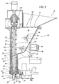
- Figure 2 shows a preferred embodiment 10 of an apparatus for packaging a product in a corresponding container, the container being in the form of a wrapper W containing the product and comprising a respective sheet of foldable material which, in use, is wrapped around and in contact with the product P to be packaged.
- the package W has, in use, a bottom wall W1, an upper wall or top W2, between which one or more peripheral side walls W3 extend and which together define an internal space for containing the product P.
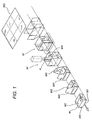
- the flat wrapper or sheet W0 for example made from aluminium foil or plastic film, is partly preformed or folded into a cup shape, open at the top W', as illustrated in Figure 1 , so as to receive the predetermined product portion P, and is then closed over the selfsame product by folding corresponding side wall portions W3' extending upwards from the sides of the product after the latter has been filled into the internal space and the upper tabs W3', W3' of the wrapper are folded down and joined or sealed to each other.
- the product is in the form of a semi-solid paste, that is to say, a product which has a plastic, or deformable, consistency such as to maintain the shape given to it.
- the product is a food product such as yeast, margarine, butter, stock cube paste or the like.
- the apparatus 10 comprises container feed means 11, which are in the form of a circular feed table but which might be embodied in any other suitable manner, for example an endless conveyor belt extending along a linear feed path.
- the feed table comprises shaped seats or pockets, denoted by the reference numeral 13, which accommodate the cup-shaped container or wrapper.
- the apparatus 10 also comprises a means, or device 12, for filling the respective containers W, the device 12 comprising respective means 14 for dosing a predetermined product portion, means 16 for feeding the product to the dosing means 14, in the form of a respective tank containing the product, and means 18 for loading the product into the feed means 16, the loading means 18 being, as illustrated, in the form of an upper hopper, whose bottom is in communication through corresponding holes 18' with the feed tank or means 16.
- the means for dosing a predetermined product portion more specifically comprises a screw feeder 20 having a respective shaft 22 mounting a spiral 24 which engages and feeds the product, the screw feeder being housed in a perimetric surface 26 defining a dosing chamber 28.
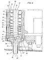
- the spiral 24 for engaging and feeding the product has a peripheral or outer edge 24' which extends at or in the vicinity of the perimetric surface of the dosing chamber 28, as may be easily inferred from Figures 3 and 4 .
- the screw feeder 20 is driven in rotation about its own axis between a first working condition, where product is fed until the predetermined product portion has been defined, and a second working condition, where product feed is interrupted, in particular by stopping the screw feeder, after the predetermined product portion has been defined.
- the screw feeder 20 might also be driven in an angular direction opposite to the product feed direction so as to back-feed the product for a short distance towards the dispensing mouth, thereby making it easier for only the predetermined product portion to drop out.
- the dosing chamber 28 also has a terminal portion, or bottom end 30, with a tapered product conveying surface, more specifically in the form of a conical surface 31, converging downwardly towards the outlet of the dosing chamber, whilst the rest of the conveying chamber 28 is defined by a tubular body 32 forming a cylindrical inside surface 33, the conical end portion 30 being located on the bottom extension of the tubular body 32.
- the tubular body 32 has a gap 33' which houses means for thermally conditioning the product inside the dosing chamber 28, being, more specifically, in the form of means for heating the product. That way, the product can be kept in optimum conditions for dosing.
- the free bottom, or downstream, end 20' of the dosing screw feeder 20, as illustrated, extends into the conical end portion 30 of the dosing chamber, that is to say, into the conical end surface 31.
- the free bottom, or downstream, end 20' of the dosing screw feeder 20 has a respective spiral portion whose diameter is reduced progressively towards the end of the selfsame screw feeder, and has a conical outer profile which mates with, that is to say, has the same taper as, the conical profile of the inner surface 31 of the end portion 30 of the dosing chamber 28.
- the respective end portion 22' of the shaft 22 of the dosing screw feeder 20 is in turn smaller in diameter than the main shaft portion 22".
- the respective end portion 22' of the shaft 22 of the dosing screw feeder at the end 20' of the dosing screw feeder has a reduced diameter.
- the shaft also has a conical portion, or conical outer profile 22"', in particular having the same taper as the bottom part of the dosing chamber 31.
- the tapered diameter of the spiral also guarantees that the product flows towards the outlet in a sufficient quantity.
- This screw feeder having an end portion 20' with tapered diameter, makes it possible to position the feeding and dosing means 20 very close to the dispensing mouth so that the predetermined product portion can be effectively dosed using only the screw feeder.
- the quantity of pasty product between the end of the screw feeder and the discharge mouth is in a compressed, reciprocally adherent condition such that the product feed motion, once the rotation of the screw feeder is stopped or reversed relative to the rotation direction of product feed, is modified or stopped. This allows the pasty product to be effectively dosed without using any components other than the screw feeder.
- the dosing means comprise a product discharge mouth 34.
- the predetermined product portion is fed out of the dosing screw feeder 20 through the product discharge mouth 34.
- the dosing means also comprise a spout 36 that terminates with the mouth 34 which dispenses the predetermined product portion.
- the spout 36 extends downstream of the tapered conveying surface 31 and is in the form of a respective tube of quadrangular cross section and having an inlet opening 38 leading into the tapered conveying surface 31 and an outlet opening defining the discharge mouth 34.
- the spout 36 extends downwardly from the dosing chamber 28, in particular downwardly from the end portion 30 of the dosing chamber.
- a product bar cutting element 40' in the form of a thin rod movable between a rest position and an active position where it cuts the product bar once the predetermined product portion has been expelled from the discharge mouth 34 and placed in the container.
- the product bar cutting element 40' is supported by arms 41,41 which are rotatably attached to the end portion 30 of the dosing chamber.
- means 16 are provided for feeding the product to the dosing means, in the form of a tank 16 for containing the product and from which the dosing chamber 28 extends.
- the dosing chamber 28 extends downwardly from the tank 16.
- the dosing screw feeder 20 has an upstream portion 20" for capturing the product to be fed to the dosing chamber 28.
- the dosing screw feeder 20 has a portion 20" for inserting the product into the dosing chamber 28.
- the dosing screw feeder thus has an upstream portion 20" for capturing the product or inserting the product into the dosing chamber and which extends into the product containment tank, and a downstream portion for compressing the product or dosing a predetermined product portion to be inserted into a respective container, in particular into a respective wrapper, the downstream portion of the screw feeder being housed in the dosing chamber 28.
- the pitch of the product engagement and feed spiral of the dosing screw feeder 20 is variable.
- the dosing screw feeder 20 spiral pitch at the feed tank 16, that is, at the part of the screw feeder which extends into the feed tank 16, is greater than the pitch of the spiral in the dosing chamber 28, and more specifically, is greater than the pitch of the screw feeder spiral at the bottom 30 of the selfsame dosing chamber 28.
- the spiral pitch is greater in the capturing zone. As illustrated the spiral extends inside and at the side of the product containment tank 16.
- the spiral pitch is thus progressively reduced to reach a minimum pitch at the end portion of the dosing chamber, in particular at the conical end portion 31 of the dosing chamber.
- the spiral pitch in the capturing zone that is, inside the feed tank, is between 1 and 10 times greater than the spiral pitch at the end, or bottom zone of the dosing chamber.
- the dosing means in particular, the product discharge mouth 34 and the container are movable relative to each other in such a way as to position the product dispensing end, or mouth 34 inside the product containment space in the container W.
- the container is movable towards the dosing means 12, which are, instead, vertically fixed.
- the container is movable vertically towards the dosing means 12, that is to say, it is movable axially relative to the dosing chamber 28 or to the dosing screw feeder 20.
- the container feed means 11 comprise a seat for housing the container 13 and which has a movable bottom 15, the latter being, more specifically, slidable in the seat 13 under the action of a corresponding rod actuated by a cam, not illustrated in the accompanying drawings, between a lowered position for normal container feed and a raised position at the container filling station, where the container is close to the dosing means and the dispensing mouth 34 is positioned inside the container, or wrapper, in the folded condition.
- this apparatus has means for feeding the containers which advance the containers stepwise to the stations, namely, a station for loading the sheet into a respective seat in a suitably folded condition to form a cup-shaped container, or wrapper, a container filling station which is located downstream of the container receiving station and where the open wrapper is filled with a predetermined product portion, and a container top closing station, which is located downstream of the container filling station and where the tabs extending upwards from the sides of the predetermined product portion are folded down onto the predetermined product portion which has been placed in the container.
- the apparatus may also comprise, downstream of the closing station where the protruding side tabs of the wrapper are folded, a further station for closing, joining or heat sealing the upper closing tabs of the wrapper, or container.
- a still further station defines outfeed means from which the product package is conveyed to a further apparatus for packing the packages into cartons or the like.
- advantageous means 40, 40' are provided for urging the product towards the dosing means.
- the dosing tank 16 comprises a plurality of peripheral containment walls and a bottom wall 16', in particular, a wall which is slightly inclined towards the dosing chamber, and is open at the top and communicates with the loading hopper 18 above it, through holes 18'.
- the means 40, 40' for urging the product towards the dosing means are located inside the product feed tank 16.
- the means 40, 40' for urging the product towards the dosing means comprise a respective blade rotor having a rotary shaft 42, in particular directed horizontally, from which radial blades 44 extend.
- the shaft 42 of the respective urger with blades 40, 40' extends transversally to the shaft, or axis, of the screw feeder 20, and transversally to the axis of the dosing chamber 28.
- a first and a second means 40, 40' are provided inside the containment tank 16, at different heights, for urging the product towards the dosing chamber.
- a first urger 40 is located near the corresponding dosing chamber.
- a second urger with blades 40' is located in an intermediate zone between the inlet opening of the feed tank 16 and the bottom of the selfsame tank 16.
- the respective screw feeder 20 is driven by a corresponding motor 20a mounted at the top thereof and is suitably fixed at the top of, that is to say, the respective shaft 22 is fixed at the top of, the tank 16 so it can conveniently and easily be pulled out from below, through the dosing chamber 28, after disengaging respective screw feeder fastening means from the top when cleaning or maintenance has to be carried out on the screw feeder itself.
- the screw feeder 20 is fixed to the device at the top, at 120, and can be removed by pulling it out from below, from the end corresponding to the product outlet mouth.
- this apparatus advantageously comprises first and second dosing means 20, 20 which are aligned with each other along the container feed direction and which allow a pair of containers to be filled simultaneously.
- the first and second dosing means comprise respective dosing chambers 28, 28 which extend parallel to each other and which house respective screw feeders 20,20.
- the first and second dosing means extend from the same, single product containment or feed tank 16.
- the urgers with blades 40, 40' are suitably fixed to a respective side wall of the feed tank 16 through a corresponding ring nut 140, illustrated in Figure 2 , which can be conveniently removed in order to pull out the corresponding urger 40, 40', in such a way that the latter can be cleaned or substituted for urgers more suitable for the product being packaged.
- the body defining the dosing chamber 28 also comprises a cylindrical tube 50 for engaging the main part of the cylindrical body defining the dosing chamber 28 which forms a single part with the feed tank 16 and to the bottom of which the tube 50 is fixed.
- the tube 50 is advantageously made of plastic material and has, at a bottom flange of it 52, holes 53 for corresponding screws 54 for fastening the bottom portion 30 defining the conical bottom end surface 31 of the dosing chamber 28.
- the spout 36 defining the discharge mouth 34 is fixed to the body 30 defining the conical end chamber.
- the plastic tube 50 has a cylindrical inside surface defining the lower part of the dosing chamber, upstream of the conical end portion 31 of the selfsame dosing chamber.
- the plastic tube 50 may advantageously be substituted to obtain an inside surface 50' of a diameter suitable for the type of product to be packaged.
- a tube 50 which has a respective inside surface 50' defining the lower part of the dosing chamber 28, upstream of its conical end portion 31, the tube 50 being removably connected to the dosing means 28, that is, to the main body, or component 32 of the dosing chamber.
- the device of the invention can be adapted to the specific semi-solid product to be packaged. All that needs to be done is remove the tube 50 for one particular product and substitute it for another tube 50 whose inside surface has a different diameter and which is more suitable for another product to be delivered, or compressed, in the end part 50' of the dosing chamber.
- the spout for delivering the predetermined product portion to the dispensing mouth 34 is eccentric, or offset, relative to the axis of the dosing chamber and of the screw feeder along the container feed direction.
Landscapes
- Engineering & Computer Science (AREA)
- Mechanical Engineering (AREA)
- Basic Packing Technique (AREA)
- Auxiliary Devices For And Details Of Packaging Control (AREA)
- Supplying Of Containers To The Packaging Station (AREA)
Claims (14)
- Vorrichtung (10) zum Verpacken eines halbfesten pastösen Nahrungsmittelprodukts wie Hefe, Brühwürfelpaste oder sonstige Produkte, wobei das Produkt in einen entsprechenden Behälter verpackt wird, der insbesondere die Form einer Produkthülle aufweist, umfassend eine entsprechende Folie aus faltbarem Material, wobei die Vorrichtung (10) Mittel (11) zum Zuführen des Produktbehälters (W) und Mittel oder eine Einrichtung (12) zum Füllen des Behälters umfasst, umfassend jeweilige Mittel (14) zum Dosieren einer vorgegebenen Produktportion, wobei die Mittel zum Dosieren einer vorgegebenen Produktportion eine Schraubenzuführeinrichtung (20) mit einer Spirale (24) umfassen oder daraus bestehen, um das Produkt zu greifen und zuzuführen, untergebracht koaxial in einer Umfangsoberfläche (26), bildend eine Dosierkammer (28), wobei die Schraubenzuführeinrichtung (16) zwischen einem ersten Betriebszustand, in dem das Produkt zugeführt wird, bis die vorgegebene Produktportion definiert ist, und einem zweiten Betriebszustand, in dem die Produktzuführung unterbrochen wird, nachdem die vorgegebene Produktportion definiert wurde, gedreht wird, wobei die Dosierkammer einen Abschlussabschnitt (30) umfasst, bildend eine konische Produktförderungsoberfläche (31), die sich zur Auslassöffnung oder der Entladeöffnung (34) der Dosierkammer (28) hin verjüngt, wobei die Dosierschraubenzuführeinrichtung (20) einen jeweiligen freien Endabschnitt (20') aufweist, der sich im konischen Abschlussabschnitt (30) der Dosierkammer (28) erstreckt und einen Spiralabschnitt aufweist, aufweisend einen Durchmesser, der progressiv zum Abschlussende der Schraubenzuführeinrichtung mit einem konischen Außenprofil hin abnimmt, sodass er passend zum konischen Profil der Innenoberfläche (31) des Endabschnitts der Dosierkammer ausgebildet ist, wobei die Produktdosiermittel und der Behälter zueinander beweglich sind, um die Entladeöffnung im Behälter zu positionieren, dadurch gekennzeichnet, dass der Schaft (22) der Dosierschraubenzuführeinrichtung (20) einen jeweiligen Endabschnitt (22') mit einem reduzierten Durchmesser am Abschlussabschnitt der Schraubenzuführeinrichtung aufweist und dadurch, dass der Behälter zu den Dosiermitteln (12) beweglich ist.
- Vorrichtung nach Anspruch 1, dadurch gekennzeichnet, dass am Abschlussabschnitt der Schraubenzuführeinrichtung der jeweilige Endabschnitt (22''') des Schafts (22) der Dosierzuführeinrichtung (20) ein konisches Profil aufweist.
- Vorrichtung nach einem der vorhergehenden Ansprüche, dadurch gekennzeichnet, dass die Dosiermittel einen rohrförmigen Körper (32) umfassen, der eine zylindrische Produktförderungsoberfläche bildet, aufweisen, von deren freien Ende sich der Abschlussabschnitt der Dosierkammer (28) erstreckt.
- Vorrichtung nach einem der vorhergehenden Ansprüche, dadurch gekennzeichnet, dass die Dosiermittel einen Ausguss (36) umfassen, endend mit der Öffnung (34) zum Entladen der vorgegebenen Produktportion, und dass der Ausguss (36) sich nach der sich verjüngenden Förderungsoberfläche erstreckt und eine Einlassöffnung (38) aufweist, die aus der sich verjüngenden Förderungsoberfläche (30) der Dosierkammer hinausläuft, und eine Auslassöffnung, bildend die Produktentladeöffnung (34).
- Vorrichtung nach einem der vorhergehenden Ansprüche, dadurch gekennzeichnet, dass die Dosiermittel einen Tank zum Enthalten des Produkts umfassen, von dem sich die Dosierkammer (28) erstreckt, und dadurch, dass die Dosierschraubenzuführeinrichtung (20) einen Abschnitt (20") zum Einführen des Produkts in die Dosierkammer (28) aufweist.
- Vorrichtung nach einem der vorhergehenden Ansprüche, dadurch gekennzeichnet, dass die Spiralsteigung der Dosierschraubenzuführeinrichtung (20) am Produktzuführungstank (16) größer ist als die Spiralsteigung der Dosierkammer, insbesondere als die Spiralsteigung im unteren Teil der Dosierkammer (28).
- Vorrichtung nach einem der vorhergehenden Ansprüche 5 oder 6, dadurch gekennzeichnet, dass die Dosierschraubenzuführeinrichtung (20) einen Abschnitt (20") aufweist, der sich im Produktzuführungstank (16) erstreckt.
- Vorrichtung nach einem der vorhergehenden Ansprüche, dadurch gekennzeichnet, dass Mittel (40) bereitgestellt sind, um das Produkt zu den Dosiermitteln zu schieben, die sich im Zuführungstank (16) befinden, insbesondere umfassen diese Mittel zum Schieben des Produkts zu den Dosiermitteln einen Rotor mit Schaufeln (40).
- Vorrichtung nach einem der vorhergehenden Ansprüche, dadurch gekennzeichnet, dass sie erste und zweite Dosiermittel (20, 20) umfasst.
- Vorrichtung nach Anspruch 9, dadurch gekennzeichnet, dass die ersten und zweiten Dosiermittel (20, 20) zur Zuführungsrichtung der Behälter ausgerichtet sind.
- Vorrichtung nach einem der vorhergehenden Ansprüche 9 oder 10, dadurch gekennzeichnet, dass sich die ersten und zweiten Dosiermittel vom selben Produktzuführungstank (16) erstrecken.
- Vorrichtung nach einem der vorhergehenden Ansprüche, dadurch gekennzeichnet, dass die Schraubenzuführeinrichtung (20) an der Oberseite fixiert und zum Herausnehmen von der Unterseite oder vom Ende an der Produktentladeöffnung entfernbar ist.
- Vorrichtung nach einem der vorhergehenden Ansprüche, dadurch gekennzeichnet, dass die Schraubenzuführeinrichtung (20) drehbar in die entgegengesetzte Winkelrichtung gefahren wird, um das Produkt zurückzuführen.
- Vorrichtung nach einem der vorhergehenden Ansprüche, dadurch gekennzeichnet, sie eine Hülse (50) umfasst, aufweisend eine jeweilige Innenoberfläche (50'), bildend den unteren Teil der Dosierkammer, wobei die Hülse (50) entfernbar mit den Dosiermitteln verbunden ist.
Priority Applications (1)
| Application Number | Priority Date | Filing Date | Title |
|---|---|---|---|
| PL11799838T PL2643217T3 (pl) | 2010-11-22 | 2011-11-18 | Urządzenie do pakowania produktów past |
Applications Claiming Priority (2)
| Application Number | Priority Date | Filing Date | Title |
|---|---|---|---|
| ITBO2010A000698A IT1402722B1 (it) | 2010-11-22 | 2010-11-22 | Apparecchiatura per il confezionamento di un prodotto pastoso. |
| PCT/IB2011/055181 WO2012069971A1 (en) | 2010-11-22 | 2011-11-18 | Apparatus for packaging a pasty product |
Publications (2)
| Publication Number | Publication Date |
|---|---|
| EP2643217A1 EP2643217A1 (de) | 2013-10-02 |
| EP2643217B1 true EP2643217B1 (de) | 2016-02-03 |
Family
ID=43742557
Family Applications (1)
| Application Number | Title | Priority Date | Filing Date |
|---|---|---|---|
| EP11799838.5A Active EP2643217B1 (de) | 2010-11-22 | 2011-11-18 | Vorrichtung zum verpacken eines pastösen produkts |
Country Status (7)
| Country | Link |
|---|---|
| EP (1) | EP2643217B1 (de) |
| BR (1) | BR112013012567B1 (de) |
| HU (1) | HUE029015T2 (de) |
| IT (1) | IT1402722B1 (de) |
| MX (1) | MX342231B (de) |
| PL (1) | PL2643217T3 (de) |
| WO (1) | WO2012069971A1 (de) |
Families Citing this family (1)
| Publication number | Priority date | Publication date | Assignee | Title |
|---|---|---|---|---|
| CN111591484A (zh) * | 2020-05-28 | 2020-08-28 | 发泰(天津)科技有限公司 | 一种螺杆式液体药剂计量机构 |
Family Cites Families (9)
| Publication number | Priority date | Publication date | Assignee | Title |
|---|---|---|---|---|
| GB400730A (en) * | 1932-07-09 | 1933-11-02 | J G Jackson And Crockatt Ltd | Improvements in or connected with helical extrusion apparatus for filling materials into formed receptacles |
| US2589583A (en) * | 1947-05-23 | 1952-03-18 | Forrest G Thompson | Container filling machine having feed screw with cylindrical bore forming member |
| DE1085455B (de) * | 1956-02-14 | 1960-07-14 | Leidsche App Nfabriek Nv | Dosierungsgeraet fuer puderfoermige Stoffe |
| DE1268872B (de) * | 1964-10-26 | 1968-05-22 | Meyer Bruno | Selbsttaetige Dosierwaage |
| DE2924313C2 (de) * | 1979-06-15 | 1983-01-13 | Greif-Werk Maschinenfabrik GmbH, 2400 Lübeck | Vorrichtung zum Füllen von pulverisiertem Füllgut in einen Sack |
| DE8910503U1 (de) * | 1989-09-02 | 1991-01-03 | Wella Ag, 6100 Darmstadt | Vorrichtung zum dosierten Austragen von fließfähigem körnigen oder pulverförmigen Produkt |
| FR2671543B1 (fr) * | 1991-01-11 | 1993-04-09 | Egretier Sa | Dispositif automatique pour le gavage d'une pluralite de compartiments ou de recipients. |
| AT409850B (de) * | 1993-10-01 | 2002-11-25 | Josef Dipl Ing Bachler | Vorrichtung zum befüllen von säcken |
| ITBO20060430A1 (it) * | 2006-05-31 | 2007-12-01 | Sympak Corazza Spa | Dispositivo per il dosaggio di porzioni predeterminate di un prodotto pastoso |
-
2010
- 2010-11-22 IT ITBO2010A000698A patent/IT1402722B1/it active
-
2011
- 2011-11-18 PL PL11799838T patent/PL2643217T3/pl unknown
- 2011-11-18 HU HUE11799838A patent/HUE029015T2/en unknown
- 2011-11-18 BR BR112013012567A patent/BR112013012567B1/pt active IP Right Grant
- 2011-11-18 EP EP11799838.5A patent/EP2643217B1/de active Active
- 2011-11-18 WO PCT/IB2011/055181 patent/WO2012069971A1/en not_active Ceased
- 2011-11-18 MX MX2013005785A patent/MX342231B/es active IP Right Grant
Also Published As
| Publication number | Publication date |
|---|---|
| HUE029015T2 (en) | 2017-02-28 |
| ITBO20100698A1 (it) | 2012-05-23 |
| EP2643217A1 (de) | 2013-10-02 |
| BR112013012567A2 (pt) | 2017-10-17 |
| WO2012069971A1 (en) | 2012-05-31 |
| MX342231B (es) | 2016-09-21 |
| IT1402722B1 (it) | 2013-09-18 |
| PL2643217T3 (pl) | 2016-08-31 |
| BR112013012567B1 (pt) | 2019-12-03 |
| MX2013005785A (es) | 2013-10-01 |
Similar Documents
| Publication | Publication Date | Title |
|---|---|---|
| US6904737B2 (en) | Dispensing apparatus and method of dispensing | |
| CA2614871C (en) | Device and method for filling foil bags with food | |
| US3828660A (en) | Machine for making ice cream cookie sandwiches and similar food products | |
| JP2005008282A (ja) | 粉粒体の供給装置 | |
| JP2017523095A (ja) | 抽出または注入飲料用の使い捨てカプセルの容器への充填のためのユニットおよび方法 | |
| WO2019031558A1 (ja) | 固形物供給装置および当該固形物供給装置を備えた食品の製造装置 | |
| EP2643217B1 (de) | Vorrichtung zum verpacken eines pastösen produkts | |
| CN206485606U (zh) | 立式螺杆包装机 | |
| EP3650359B1 (de) | Vorrichtung, system und verfahren zur befüllung von verpackungen mit festen lebensmitteln | |
| JP4274569B2 (ja) | 食品素材の押し出し方法及びその装置 | |
| CN117485668B (zh) | 一种全气动三边封辣椒酱包装机及其使用方法 | |
| CN208360599U (zh) | 酱腌菜无损分料计量罐装真空包装一体机 | |
| KR101587905B1 (ko) | 스틱제품 포장기용 이중 구조 충진 파이프 어셈블리 | |
| CN205396708U (zh) | 粉体自动卸料包装机 | |
| KR200475934Y1 (ko) | 견과류 공급 제어장치 | |
| CN209241372U (zh) | 带有小袋排气功能的颗粒分装机 | |
| EP3359454B1 (de) | Vorrichtung zum dosieren von jeweiligen portionen eines produkts | |
| CN210175304U (zh) | 采用带嘴自立袋存放八宝粥的灌装设备 | |
| US10730647B1 (en) | Systems and methods for automated food packaging | |
| CN212915362U (zh) | 一种新型水溶性食用香精的生产装置 | |
| CN115535326B (zh) | 一种调味料料包分装装置 | |
| CN215285397U (zh) | 一种饼干包装自动封口装置 | |
| CN219949470U (zh) | 料包形态类预制食材的投放机构 | |
| RU40298U1 (ru) | Клапан дозатора | |
| CN213921615U (zh) | 一种牛油定量包装的背封式包装机系统 |
Legal Events
| Date | Code | Title | Description |
|---|---|---|---|
| PUAI | Public reference made under article 153(3) epc to a published international application that has entered the european phase |
Free format text: ORIGINAL CODE: 0009012 |
|
| 17P | Request for examination filed |
Effective date: 20130522 |
|
| AK | Designated contracting states |
Kind code of ref document: A1 Designated state(s): AL AT BE BG CH CY CZ DE DK EE ES FI FR GB GR HR HU IE IS IT LI LT LU LV MC MK MT NL NO PL PT RO RS SE SI SK SM TR |
|
| DAX | Request for extension of the european patent (deleted) | ||
| 17Q | First examination report despatched |
Effective date: 20140701 |
|
| GRAP | Despatch of communication of intention to grant a patent |
Free format text: ORIGINAL CODE: EPIDOSNIGR1 |
|
| INTG | Intention to grant announced |
Effective date: 20150720 |
|
| GRAS | Grant fee paid |
Free format text: ORIGINAL CODE: EPIDOSNIGR3 |
|
| GRAA | (expected) grant |
Free format text: ORIGINAL CODE: 0009210 |
|
| AK | Designated contracting states |
Kind code of ref document: B1 Designated state(s): AL AT BE BG CH CY CZ DE DK EE ES FI FR GB GR HR HU IE IS IT LI LT LU LV MC MK MT NL NO PL PT RO RS SE SI SK SM TR |
|
| REG | Reference to a national code |
Ref country code: GB Ref legal event code: FG4D |
|
| REG | Reference to a national code |
Ref country code: AT Ref legal event code: REF Ref document number: 773557 Country of ref document: AT Kind code of ref document: T Effective date: 20160215 Ref country code: CH Ref legal event code: EP |
|
| REG | Reference to a national code |
Ref country code: IE Ref legal event code: FG4D |
|
| REG | Reference to a national code |
Ref country code: DE Ref legal event code: R096 Ref document number: 602011023098 Country of ref document: DE |
|
| REG | Reference to a national code |
Ref country code: CH Ref legal event code: NV Representative=s name: BUGNION S.A., CH |
|
| REG | Reference to a national code |
Ref country code: LT Ref legal event code: MG4D Ref country code: NL Ref legal event code: MP Effective date: 20160203 |
|
| REG | Reference to a national code |
Ref country code: AT Ref legal event code: MK05 Ref document number: 773557 Country of ref document: AT Kind code of ref document: T Effective date: 20160203 |
|
| PG25 | Lapsed in a contracting state [announced via postgrant information from national office to epo] |
Ref country code: GR Free format text: LAPSE BECAUSE OF FAILURE TO SUBMIT A TRANSLATION OF THE DESCRIPTION OR TO PAY THE FEE WITHIN THE PRESCRIBED TIME-LIMIT Effective date: 20160504 Ref country code: HR Free format text: LAPSE BECAUSE OF FAILURE TO SUBMIT A TRANSLATION OF THE DESCRIPTION OR TO PAY THE FEE WITHIN THE PRESCRIBED TIME-LIMIT Effective date: 20160203 Ref country code: ES Free format text: LAPSE BECAUSE OF FAILURE TO SUBMIT A TRANSLATION OF THE DESCRIPTION OR TO PAY THE FEE WITHIN THE PRESCRIBED TIME-LIMIT Effective date: 20160203 Ref country code: FI Free format text: LAPSE BECAUSE OF FAILURE TO SUBMIT A TRANSLATION OF THE DESCRIPTION OR TO PAY THE FEE WITHIN THE PRESCRIBED TIME-LIMIT Effective date: 20160203 Ref country code: NO Free format text: LAPSE BECAUSE OF FAILURE TO SUBMIT A TRANSLATION OF THE DESCRIPTION OR TO PAY THE FEE WITHIN THE PRESCRIBED TIME-LIMIT Effective date: 20160503 |
|
| PG25 | Lapsed in a contracting state [announced via postgrant information from national office to epo] |
Ref country code: IS Free format text: LAPSE BECAUSE OF FAILURE TO SUBMIT A TRANSLATION OF THE DESCRIPTION OR TO PAY THE FEE WITHIN THE PRESCRIBED TIME-LIMIT Effective date: 20160603 Ref country code: RS Free format text: LAPSE BECAUSE OF FAILURE TO SUBMIT A TRANSLATION OF THE DESCRIPTION OR TO PAY THE FEE WITHIN THE PRESCRIBED TIME-LIMIT Effective date: 20160203 Ref country code: SE Free format text: LAPSE BECAUSE OF FAILURE TO SUBMIT A TRANSLATION OF THE DESCRIPTION OR TO PAY THE FEE WITHIN THE PRESCRIBED TIME-LIMIT Effective date: 20160203 Ref country code: LV Free format text: LAPSE BECAUSE OF FAILURE TO SUBMIT A TRANSLATION OF THE DESCRIPTION OR TO PAY THE FEE WITHIN THE PRESCRIBED TIME-LIMIT Effective date: 20160203 Ref country code: AT Free format text: LAPSE BECAUSE OF FAILURE TO SUBMIT A TRANSLATION OF THE DESCRIPTION OR TO PAY THE FEE WITHIN THE PRESCRIBED TIME-LIMIT Effective date: 20160203 Ref country code: NL Free format text: LAPSE BECAUSE OF FAILURE TO SUBMIT A TRANSLATION OF THE DESCRIPTION OR TO PAY THE FEE WITHIN THE PRESCRIBED TIME-LIMIT Effective date: 20160203 Ref country code: LT Free format text: LAPSE BECAUSE OF FAILURE TO SUBMIT A TRANSLATION OF THE DESCRIPTION OR TO PAY THE FEE WITHIN THE PRESCRIBED TIME-LIMIT Effective date: 20160203 Ref country code: PT Free format text: LAPSE BECAUSE OF FAILURE TO SUBMIT A TRANSLATION OF THE DESCRIPTION OR TO PAY THE FEE WITHIN THE PRESCRIBED TIME-LIMIT Effective date: 20160603 |
|
| PG25 | Lapsed in a contracting state [announced via postgrant information from national office to epo] |
Ref country code: DK Free format text: LAPSE BECAUSE OF FAILURE TO SUBMIT A TRANSLATION OF THE DESCRIPTION OR TO PAY THE FEE WITHIN THE PRESCRIBED TIME-LIMIT Effective date: 20160203 Ref country code: EE Free format text: LAPSE BECAUSE OF FAILURE TO SUBMIT A TRANSLATION OF THE DESCRIPTION OR TO PAY THE FEE WITHIN THE PRESCRIBED TIME-LIMIT Effective date: 20160203 |
|
| REG | Reference to a national code |
Ref country code: DE Ref legal event code: R097 Ref document number: 602011023098 Country of ref document: DE |
|
| PG25 | Lapsed in a contracting state [announced via postgrant information from national office to epo] |
Ref country code: CZ Free format text: LAPSE BECAUSE OF FAILURE TO SUBMIT A TRANSLATION OF THE DESCRIPTION OR TO PAY THE FEE WITHIN THE PRESCRIBED TIME-LIMIT Effective date: 20160203 Ref country code: SK Free format text: LAPSE BECAUSE OF FAILURE TO SUBMIT A TRANSLATION OF THE DESCRIPTION OR TO PAY THE FEE WITHIN THE PRESCRIBED TIME-LIMIT Effective date: 20160203 Ref country code: SM Free format text: LAPSE BECAUSE OF FAILURE TO SUBMIT A TRANSLATION OF THE DESCRIPTION OR TO PAY THE FEE WITHIN THE PRESCRIBED TIME-LIMIT Effective date: 20160203 Ref country code: RO Free format text: LAPSE BECAUSE OF FAILURE TO SUBMIT A TRANSLATION OF THE DESCRIPTION OR TO PAY THE FEE WITHIN THE PRESCRIBED TIME-LIMIT Effective date: 20160203 |
|
| PLBE | No opposition filed within time limit |
Free format text: ORIGINAL CODE: 0009261 |
|
| STAA | Information on the status of an ep patent application or granted ep patent |
Free format text: STATUS: NO OPPOSITION FILED WITHIN TIME LIMIT |
|
| PG25 | Lapsed in a contracting state [announced via postgrant information from national office to epo] |
Ref country code: BE Free format text: LAPSE BECAUSE OF FAILURE TO SUBMIT A TRANSLATION OF THE DESCRIPTION OR TO PAY THE FEE WITHIN THE PRESCRIBED TIME-LIMIT Effective date: 20160203 |
|
| 26N | No opposition filed |
Effective date: 20161104 |
|
| PG25 | Lapsed in a contracting state [announced via postgrant information from national office to epo] |
Ref country code: SI Free format text: LAPSE BECAUSE OF FAILURE TO SUBMIT A TRANSLATION OF THE DESCRIPTION OR TO PAY THE FEE WITHIN THE PRESCRIBED TIME-LIMIT Effective date: 20160203 Ref country code: BG Free format text: LAPSE BECAUSE OF FAILURE TO SUBMIT A TRANSLATION OF THE DESCRIPTION OR TO PAY THE FEE WITHIN THE PRESCRIBED TIME-LIMIT Effective date: 20160503 |
|
| REG | Reference to a national code |
Ref country code: HU Ref legal event code: AG4A Ref document number: E029015 Country of ref document: HU |
|
| GBPC | Gb: european patent ceased through non-payment of renewal fee |
Effective date: 20161118 |
|
| REG | Reference to a national code |
Ref country code: IE Ref legal event code: MM4A |
|
| REG | Reference to a national code |
Ref country code: FR Ref legal event code: ST Effective date: 20170731 |
|
| PG25 | Lapsed in a contracting state [announced via postgrant information from national office to epo] |
Ref country code: LU Free format text: LAPSE BECAUSE OF NON-PAYMENT OF DUE FEES Effective date: 20161130 |
|
| PG25 | Lapsed in a contracting state [announced via postgrant information from national office to epo] |
Ref country code: FR Free format text: LAPSE BECAUSE OF NON-PAYMENT OF DUE FEES Effective date: 20161130 |
|
| PG25 | Lapsed in a contracting state [announced via postgrant information from national office to epo] |
Ref country code: GB Free format text: LAPSE BECAUSE OF NON-PAYMENT OF DUE FEES Effective date: 20161118 Ref country code: IE Free format text: LAPSE BECAUSE OF NON-PAYMENT OF DUE FEES Effective date: 20161118 |
|
| PG25 | Lapsed in a contracting state [announced via postgrant information from national office to epo] |
Ref country code: CY Free format text: LAPSE BECAUSE OF FAILURE TO SUBMIT A TRANSLATION OF THE DESCRIPTION OR TO PAY THE FEE WITHIN THE PRESCRIBED TIME-LIMIT Effective date: 20160203 |
|
| PG25 | Lapsed in a contracting state [announced via postgrant information from national office to epo] |
Ref country code: MC Free format text: LAPSE BECAUSE OF FAILURE TO SUBMIT A TRANSLATION OF THE DESCRIPTION OR TO PAY THE FEE WITHIN THE PRESCRIBED TIME-LIMIT Effective date: 20160203 Ref country code: MK Free format text: LAPSE BECAUSE OF FAILURE TO SUBMIT A TRANSLATION OF THE DESCRIPTION OR TO PAY THE FEE WITHIN THE PRESCRIBED TIME-LIMIT Effective date: 20160203 |
|
| PG25 | Lapsed in a contracting state [announced via postgrant information from national office to epo] |
Ref country code: MT Free format text: LAPSE BECAUSE OF NON-PAYMENT OF DUE FEES Effective date: 20161118 |
|
| PG25 | Lapsed in a contracting state [announced via postgrant information from national office to epo] |
Ref country code: AL Free format text: LAPSE BECAUSE OF FAILURE TO SUBMIT A TRANSLATION OF THE DESCRIPTION OR TO PAY THE FEE WITHIN THE PRESCRIBED TIME-LIMIT Effective date: 20160203 |
|
| P01 | Opt-out of the competence of the unified patent court (upc) registered |
Effective date: 20230517 |
|
| REG | Reference to a national code |
Ref country code: CH Ref legal event code: U11 Free format text: ST27 STATUS EVENT CODE: U-0-0-U10-U11 (AS PROVIDED BY THE NATIONAL OFFICE) Effective date: 20251201 |
|
| PGFP | Annual fee paid to national office [announced via postgrant information from national office to epo] |
Ref country code: HU Payment date: 20251103 Year of fee payment: 15 |
|
| PGFP | Annual fee paid to national office [announced via postgrant information from national office to epo] |
Ref country code: DE Payment date: 20251022 Year of fee payment: 15 |
|
| PGFP | Annual fee paid to national office [announced via postgrant information from national office to epo] |
Ref country code: IT Payment date: 20251022 Year of fee payment: 15 |
|
| PGFP | Annual fee paid to national office [announced via postgrant information from national office to epo] |
Ref country code: TR Payment date: 20251022 Year of fee payment: 15 |
|
| PGFP | Annual fee paid to national office [announced via postgrant information from national office to epo] |
Ref country code: CH Payment date: 20251201 Year of fee payment: 15 |
|
| PGFP | Annual fee paid to national office [announced via postgrant information from national office to epo] |
Ref country code: PL Payment date: 20251024 Year of fee payment: 15 |