EP2642899B1 - Möbel mit Möbelantrieb - Google Patents
Möbel mit Möbelantrieb Download PDFInfo
- Publication number
- EP2642899B1 EP2642899B1 EP11810531.1A EP11810531A EP2642899B1 EP 2642899 B1 EP2642899 B1 EP 2642899B1 EP 11810531 A EP11810531 A EP 11810531A EP 2642899 B1 EP2642899 B1 EP 2642899B1
- Authority
- EP
- European Patent Office
- Prior art keywords
- sensor
- furniture
- electric motor
- drive
- switching device
- Prior art date
- Legal status (The legal status is an assumption and is not a legal conclusion. Google has not performed a legal analysis and makes no representation as to the accuracy of the status listed.)
- Active
Links
Images



Classifications
-
- A—HUMAN NECESSITIES
- A47—FURNITURE; DOMESTIC ARTICLES OR APPLIANCES; COFFEE MILLS; SPICE MILLS; SUCTION CLEANERS IN GENERAL
- A47B—TABLES; DESKS; OFFICE FURNITURE; CABINETS; DRAWERS; GENERAL DETAILS OF FURNITURE
- A47B88/00—Drawers for tables, cabinets or like furniture; Guides for drawers
- A47B88/40—Sliding drawers; Slides or guides therefor
- A47B88/453—Actuated drawers
- A47B88/457—Actuated drawers operated by electrically-powered actuation means
Definitions
- the present invention relates to a piece of furniture according to the features of the preamble of claim 1.
- a generic furniture go for example from the WO 2007/009133 A1 the applicant. This document has made it its mission to further develop a furniture drive so that the risk of unintentional triggering is reduced. This was solved in such a way that depending on the opening state of the movable furniture part, namely a drawer of different high threshold value for the triggering of the electric motor (trigger sensitivity) was provided. In the closed end position of the movable furniture part, the threshold value was lower than the threshold value for the fully opened end position of the movable furniture part. This is based on the consideration that the movable furniture part is exposed in its closed end position hardly unintentional forces.
- the invention is based on the surprising realization that it is even possible in the provision of two identical sensors, each of which has the same triggering threshold, to effectively achieve a different triggering sensitivity, depending on whether the movable drawer is in the closed end position or Not.
- the one (second) sensor is coupled to a mechanical control sensor independently of the transmission and thus directly on an external force of a user the movable drawer can react.
- the application of force by the user preferably does not take place directly on the mechanical adjusting sensor, but indirectly on the movable drawer. Since the mechanical adjusting sensor is arranged between the moving drawer and the furniture body, pressing and / or pulling a user on the movable drawer leads to a movement of the mechanical adjusting sensor, which is detected directly by the corresponding (second) sensor.
- the first sensor is mechanically coupled to the transmission. This results in a larger inertia, that is, in other words, the sensor takes longer to transmit a trigger signal to the switching device.
- the mechanical adjusting sensor is no longer in contact with the drawer. If a user exerts a compressive or tensile force on the movable drawer, only the first sensor can report this to the switching device, since the second sensor does not receive a signal from the mechanical position sensor. In this case, however, results in a trigger sensitivity, which is higher than in the closed end position, since the first sensor, which is not absolutely necessary - even if it is identical to the second sensor - detected only via the transmission, the train or pressure application of the user ,
- first and the second sensor identical, but to select a sensor for the first sensor, which from the outset has a lower triggering sensitivity than the second sensor.
- the second sensor such a sensor, which in itself has a lower trigger sensitivity than the first sensor, if this is overcompensated by the mechanical coupling of the first sensor with the transmission.
- the mechanical adjusting sensor may be formed, for example, as a displaceably mounted plunger or pivotally mounted lever, as is known per se. Particularly suitable is a pivotally mounted lever, such as the subject of the WO 2010/081178 A1 the applicant.
- a control or regulating device for the electric motor is provided, and particularly preferably the switching device is formed in the control or regulating device.
- the invention makes it possible, however, not to have to provide any elaborate control or regulating device and instead to provide only a simple switching device.
- Fig. 1 shows in schematic form a furniture drive 1 of a piece of furniture according to the invention.
- This has an electric motor 3, which via an output shown here as a gear 2, not shown in detail movable furniture part, namely a drawer 11 (see, for example Fig. 2 ) drives.
- a transmission 4 is arranged or switched.
- a switching device 5 is provided for switching the electric motor 3.
- a first sensor 6 is mechanically coupled to the transmission 4 and supplies its signals to the switching device 5.
- a second sensor 7 is coupled to a mechanical adjusting sensor 8 and also supplies its signals to the switching device 5.
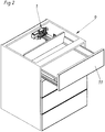
- Fig. 2 shows a perspective view of an example of an inventive furniture 9 with a furniture body 10 and a movable drawer 11, which is driven by a furniture drive 1 according to the invention.
- the movable drawer 11 is shown in a position between the closed end position in the furniture body 10 and the fully open end position. Since it is a handleless movable drawer 11 in the present case, a slight gap between the front panel of the movable drawer 11 and the end face of the furniture body 10 is provided in a known manner in the closed end position of the movable drawer 11 to a trip path for the Provide release of the electric motor 3 by applying pressure to the drawer 11.
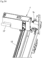
- Fig. 3a shows the furniture drive 1 according to the invention in the installed position of Fig. 2
- a furniture drive 1 is fixedly connected to the movable drawer 11.
- the electric motor 3 can transmit power to the exemplary illustrated rack 13. This leads to a movement of the movable drawer 11.
- an inventive furniture drive 1 is provided only on one side of the movable drawer 11.
- a known synchronization rod 12 is provided, which allows a portion of the force of the electric motor 3 to a arranged on the other side of the movable drawer 11 further gear. This meshes with another rack (not shown).
- Gear and rack are shown only as an example. It could be used a completely different output 2, for example in the form of a friction wheel or in the form of a cable.
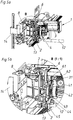
- the first sensor 6 (here designed as a Hall sensor - see for example Fig. 5b ) mechanically coupled to the transmission 4.
- the transmission 4 has the function to transmit the driving force of the electric motor 3 in a suitable translation to the output 2 or the synchronization rod 12. This is done by the worm 31 of the electric motor 3 via the gears 41, 42, 43, 44 and 45. The last gear 45 finally meshes with the output 2. The mechanical coupling of the first sensor 6 with the gear 4 takes place via the gear 43 and the gears 62 and 61.
- the furniture drive 1 has a control device in which the switching device 5 is formed. This is arranged on a non-illustrated in the figures board in a known manner.
Landscapes
- Power-Operated Mechanisms For Wings (AREA)
Description
- Die vorliegende Erfindung betrifft ein Möbel gemäß den Merkmalen des Oberbegriffs des Anspruchs 1.
- Ein gattungsgemäßes Möbel gehen beispielsweise aus der
WO 2007/009133 A1 der Anmelderin hervor. Diese Schrift hatte es sich zur Aufgabe gemacht, einen Möbelantrieb derart weiterzubilden, dass die Gefahr einer unbeabsichtigten Auslösung verringert wird. Dies wurde derart gelöst, dass ein je nach Öffnungszustand des bewegbaren Möbelteils, nämlich einer Schublade unterschiedlich hoher Schwellwert für die Auslösung des Elektromotors (Auslösesensibilität) vorgesehen war. In der geschlossenen Endlage des bewegbaren Möbelteils war der Schwellwert niedriger als der Schwellwert für die voll geöffnete Endlage des bewegbaren Möbelteils. Dies geht auf die Überlegung zurück, dass das bewegbare Möbelteil in seiner geschlossenen Endlage kaum unbeabsichtigten Krafteinflüssen ausgesetzt ist. In der voll geöffneten Endlage des bewegbaren Möbelteils kann es hingegen zu unbeabsichtigten Krafteinflüssen durch das Be- oder Entladen des bewegbaren Möbelteils mit Füllgütern kommen. Dem wird durch den höher gewählten Schwellwert in dieser Position des bewegbaren Möbelteils Rechnung getragen. -
DE 20 2009 009 450 U1 undDE 20 2007 006 689 U1 offenbaren Möbelantriebe für Schiebetüren bzw. Möbelklappen. Aufgabe der Erfindung ist es, ein gattungsgemäßes Möbel bereitzustellen, welches unter Beibehaltung des oben diskutierten Konzeptes eine Alternativlösung darstellt. Diese Aufgabe wird durch ein Möbel mit den Merkmalen des Anspruchs 1 gelöst. Vorteilhafte Ausführungsformen der Erfindung sind in den abhängigen Ansprüchen definiert. - Die Erfindung beruht auf der überraschenden Erkenntnis, dass es sogar beim Vorsehen zweier baugleicher Sensoren, die jeder für sich genommen dieselbe Auslöseschwelle aufweisen, möglich ist, effektiv eine unterschiedliche Auslösesensibilität zu erzielen, je nachdem, ob sich die bewegbare Schublade in der geschlossenen Endlage befindet oder nicht. Dies wird dadurch erreicht, dass der eine (zweite) Sensor unabhängig vom Getriebe mit einem mechanischen Stellfühler gekoppelt ist und so unmittelbar auf eine externe Krafteinwirkung eines Benutzers auf die bewegbare Schublade reagieren kann. Die Kraftausübung des Benutzers erfolgt dabei bevorzugt nicht unmittelbar auf den mechanischen Stellfühler, sondern indirekt auf die bewegbare Schublade. Da der mechanische Stellfühler zwischen der bewegten Schublade und dem Möbelkorpus angeordnet ist, führt eine Druck- und/oder Zugausübung eines Benutzers auf die bewegbare Schublade zu einer Bewegung des mechanischen Stellfühlers, welche vom entsprechenden (zweiten) Sensor unmittelbar detektiert wird.
- Der erste Sensor ist hingegen mechanisch mit dem Getriebe gekoppelt. Dadurch ergibt sich eine größere Trägheit, das heißt mit anderen Worten, der Sensor benötigt länger, um der Schalteinrichtung ein Auslösesignal zu übermitteln.
- Befindet sich die bewegbare Schublade also in der geschlossenen Endlage im oder am Möbelkorpus und übt ein Benutzer eine Druck- oder Zugausübung auf die bewegbare Schublade aus, so kommt es sowohl zu einer Bewegung des mechanischen Stellfühlers und damit einer Auslösung des zweiten Sensors als auch zu einer Bewegung des Abtriebs und damit des Getriebes und schlussendlich des mit dem Getriebe gekoppelten ersten Sensors. Da der zweite Sensor aber aufgrund seiner unmittelbaren Auslösung schneller auslöst als der erste Sensor, ergibt sich effektiv eine Auslösesensibilität, die der Auslösesensibilität des zweiten Sensors, welche sich aufgrund seiner Bauart ergibt, im Wesentlichen entspricht.
- Befindet sich die bewegbare Schublade nicht in seiner geschlossenen Endlage, das heißt wurde es entweder nur teilweise oder vollständig in Richtung der geöffneten Endlage bewegt, so liegt der mechanische Stellfühler nicht mehr an der Schublade an. Übt nun ein Benutzer eine Druck- oder Zugkraft auf die bewegbare Schublade aus, so kann nur der erste Sensor dies an die Schalteinrichtung melden, da ja der zweite Sensor vom mechanischen Stellfühler kein Signal erhält. In diesem Fall ergibt sich aber eine Auslösesensibilität, die höher ist als in der geschlossenen Endlage, da der erste Sensor, was nicht unbedingt erforderlich ist - auch wenn er baugleich zum zweiten Sensor ist - nur über das Getriebe die Zug- oder Druckausübung des Benutzers detektiert.
- Alternativ oder zusätzlich ist es natürlich möglich, den ersten und den zweiten Sensor nicht baugleich zu wählen, sondern für den ersten Sensor einen Sensor auszuwählen, der von vorneherein eine niedrigere Auslösesensibilität aufweist als der zweite Sensor. Im gewissen Rahmen wäre es sogar möglich, als zweiten Sensor einen solchen Sensor zu wählen, der an sich eine geringere Auslösesensibilität aufweist als der erste Sensor, sofern dies durch die mechanische Kopplung des ersten Sensors mit dem Getriebe überkompensiert wird.
- Der mechanische Stellfühler kann beispielsweise als verschiebbar gelagerter Stößel oder schwenkbar gelagerter Hebel ausgebildet sein, wie dies an sich bekannt ist. Besonders geeignet ist ein schwenkbar gelagerter Hebel, wie er beispielsweise Gegenstand der
WO 2010/081178 A1 der Anmelderin ist. - Bevorzugt ist eine Steuer- oder Regelvorrichtung für den Elektromotor vorgesehen und besonders bevorzugt ist die Schalteinrichtung in der Steuer- oder Regelvorrichtung ausgebildet. Die Erfindung ermöglicht es aber, gerade keine aufwändige Steuer- oder Regelvorrichtung vorsehen zu müssen und stattdessen nur eine einfache Schalteinrichtung bereitzustellen.
- Weitere Vorteile und Einzelheiten der Erfindung ergeben sich anhand der Figuren sowie der dazugehörigen Figurenbeschreibung. Dabei zeigen:
- Fig. 1
- eine schematische Darstellung eines Möbelantriebs eines erfindungsgemäßen Möbels,
- Fig. 2
- ein erfindungsgemäßes Möbel mit einem erfindungsgemäßen Möbelantrieb in perspektivischer Ansicht und
- Fig. 3 bis 5
- unterschiedliche Ansichten des Möbelantriebs.
-
Fig. 1 zeigt in schematischer Form einen Möbelantrieb 1 eines erfindungsgemäßen Möbels. Dieser weist einen Elektromotor 3 auf, der über einen hier als Zahnrad dargestellten Abtrieb 2 ein nicht näher dargestelltes bewegbares Möbelteil, nämlich einer Schublade 11 (siehe zum BeispielFig. 2 ) antreibt. Zwischen Elektromotor 3 und Abtrieb 2 ist ein Getriebe 4 angeordnet bzw. geschalten. Weiters ist eine Schalteinrichtung 5 zum Schalten des Elektromotors 3 vorgesehen. Ein erster Sensor 6 ist mechanisch mit dem Getriebe 4 gekoppelt und führt seine Signale der Schalteinrichtung 5 zu. Ein zweiter Sensor 7 ist mit einem mechanischen Stellfühler 8 gekoppelt und führt ebenfalls seine Signale der Schalteinrichtung 5 zu. -
Fig. 2 zeigt in perspektivischer Ansicht ein Beispiel für ein erfindungsgemäßes Möbel 9 mit einem Möbelkorpus 10 und einer bewegbaren Schublade 11, welches durch einen erfindungsgemäßem Möbelantrieb 1 antreibbar ist. Die bewegbare Schublade 11 ist in einer Stellung zwischen der geschlossenen Endlage im Möbelkorpus 10 und der voll geöffneten Endlage dargestellt. Da es sich im vorliegenden Fall um eine grifflose bewegbare Schublade 11 handelt, ist in bekannter Weise auch in der geschlossenen Endlage der bewegbaren Schublade 11 ein geringfügiger Spalt zwischen der Frontblende der bewegbaren Schublade 11 und der Stirnseite des Möbelkorpus 10 vorzusehen, um einen Auslöseweg für die Auslösung des Elektromotors 3 durch Druckausübung auf die Schublade 11 bereitzustellen. -
Fig. 3a zeigt den erfindungsgemäßen Möbelantrieb 1 in Einbaulage derFig. 2 , wobei jedoch aus Gründen der Übersichtlichkeit sowohl der Möbelkorpus 10 als auch die bewegbare Schublade 11 weggelassen wurden. In diesem Ausführungsbeispiel ist ein Möbelantrieb 1 fest mit der bewegbaren Schublade 11 verbunden. Über den beispielsweise inFig. 5 erkennbaren Abtrieb 2 in Form eines Zahnrades kann der Elektromotor 3 Kraft auf die beispielhaft dargestellte Zahnstange 13 übertragen. Dies führt zu einer Bewegung der bewegbaren Schublade 11. Im gezeigten Ausführungsbeispiel ist nur auf einer Seite der bewegbaren Schublade 11 ein erfindungsgemäßer Möbelantrieb 1 vorgesehen. Um eine gleichmäßige Kraftausübung auf die bewegbare Schublade 11 zu ermöglichen, ist eine an sich bekannte Synchronisationsstange 12 vorgesehen, welche einen Teil der Kraft des Elektromotors 3 auf ein auf der anderen Seite der bewegbaren Schublade 11 angeordnetes weiteres Zahnrades gestattet. Dieses kämmt mit einer weiteren Zahnstange (nicht dargestellt). - Zahnrad und Zahnstange sind nur beispielhaft dargestellt. Es könnte ein völlig anderer Abtrieb 2 eingesetzt werden, beispielsweise in Form eines Reibrades oder in Form eines Seilzuges.
- In
Fig. 3a ist der mechanische Stellfühler 8 gut erkennbar, welcher mit einem am Möbelkorpus 10 angebrachten Anschlag 14 zusammenwirkt. Sowohl ein Andrücken des mechanischen Stellfühlers 8 an den Anschlag 14 als auch ein Abheben von diesem führen zu einer Bewegung des mechanischen Stellfühlers 8, die über einen Zahnradabschnitt 15 (siehe zum BeispielFig. 4a ) auf das Antriebsrad eines Potentiometers (zweiter Sensor 7) übertragen werden kann. - Im Gegensatz dazu ist der erste Sensor 6 (hier als Hallsensor ausgebildet - siehe zum Beispiel
Fig. 5b ) mechanisch mit dem Getriebe 4 gekoppelt. - Das Getriebe 4 hat die Funktion, die Antriebskraft des Elektromotors 3 in geeigneter Übersetzung auf den Abtrieb 2 bzw. die Synchronisationsstange 12 zu übertragen. Dies erfolgt nach der Schnecke 31 des Elektromotors 3 über die Zahnräder 41, 42, 43, 44 und 45. Das letzte Zahnrad 45 kämmt schlussendlich mit dem Abtrieb 2. Die mechanische Kopplung des ersten Sensors 6 mit dem Getriebe 4 erfolgt dabei über das Zahnrad 43 sowie die Zahnräder 62 und 61.
- Im gezeigten Ausführungsbeispiel weist der Möbelantrieb 1 eine Regelvorrichtung auf, in welcher die Schalteinrichtung 5 ausgebildet ist. Diese ist auf einer in den Figuren nicht näher dargestellten Platine in bekannter Weise angeordnet.
- Dem Fachmann bekannte Maßnahmen wie Stromzuführung wurden nicht dargestellt.
Claims (3)
- Möbel (9), mit einem Möbelkorpus (10), einer im Möbelkorpus (10) in einer geschlossenen Endlage gelagerten, bewegbaren Schublade und einem Möbelantrieb (1) mit:- einem Abtrieb (2) zur Kraftübertragung auf eine bewegbare Schublade (11),- einem Elektromotor (3),- einem Getriebe (4), das zwischen Elektromotor (3) und Abtrieb (2) geschalten ist,- einer Schalteinrichtung (5) zum Schalten des Elektromotors (3),- einem ersten Sensor (6), dessen Signale der Schalteinrichtung (5) zuführbar sind,- wobei der erste Sensor (6) mechanisch mit dem Getriebe (4) gekoppelt ist,- wobei ein zweiter Sensor (7) vorgesehen ist, dessen Signale der Schalteinrichtung (5) zuführbar sind, und- wobei der zweite Sensor (7) unabhängig vom Getriebe (4) mit einem mechanischen Stellfühler (8) gekoppelt ist und dass die Schalteinrichtung (5) den Elektromotor (3) bei Erhalt eines Signals vom ersten oder zweiten Sensor (6, 7) einschaltet,wobei der Abtrieb (2) des Möbelantriebs (1) mit der bewegbaren Schublade (11) zusammenwirkt und wobei der mechanische Stellfühler (8) zwischen Möbelkorpus (10) und der bewegbaren Schublade (11) angeordnet ist, sodass eine Druck- und/oder Zugausübung eines Benutzers auf die bewegbare Schublade (11) neben einer Bewegung des Abtriebs (2) und damit des Getriebes (4) auch eine Bewegung des am Möbelkorpus anliegenden mechanischen Stellfühlers (8) bewirkt.
- Möbelantrieb nach Anspruch 1, dadurch gekennzeichnet, dass der mechanische Stellfühler (8) als verschiebbar gelagerter Stößel oder schwenkbar gelagerter Hebel ausgebildet ist.
- Möbelantrieb nach Anspruch 1 oder 2, dadurch gekennzeichnet, dass eine Steuer- oder Regelvorrichtung für den Elektromotor (3) vorgesehen ist und vorzugsweise die Schalteinrichtung (5) in der Steuer- oder Regelvorrichtung ausgebildet ist.
Applications Claiming Priority (2)
| Application Number | Priority Date | Filing Date | Title |
|---|---|---|---|
| ATA222/2011A AT510549B1 (de) | 2011-02-21 | 2011-02-21 | Möbelantrieb |
| PCT/AT2011/000517 WO2012112998A1 (de) | 2011-02-21 | 2011-12-27 | Möbelantrieb |
Publications (2)
| Publication Number | Publication Date |
|---|---|
| EP2642899A1 EP2642899A1 (de) | 2013-10-02 |
| EP2642899B1 true EP2642899B1 (de) | 2018-04-04 |
Family
ID=45497564
Family Applications (1)
| Application Number | Title | Priority Date | Filing Date |
|---|---|---|---|
| EP11810531.1A Active EP2642899B1 (de) | 2011-02-21 | 2011-12-27 | Möbel mit Möbelantrieb |
Country Status (5)
| Country | Link |
|---|---|
| EP (1) | EP2642899B1 (de) |
| JP (1) | JP5870120B2 (de) |
| CN (1) | CN103338679B (de) |
| AT (1) | AT510549B1 (de) |
| WO (1) | WO2012112998A1 (de) |
Families Citing this family (10)
| Publication number | Priority date | Publication date | Assignee | Title |
|---|---|---|---|---|
| CN104490136A (zh) * | 2014-12-15 | 2015-04-08 | 广西大学 | 自动开关抽屉 |
| WO2018184247A1 (zh) * | 2017-04-08 | 2018-10-11 | 闲客智能(深圳)科技有限公司 | 一种智能残渣收纳框 |
| CN110840101B (zh) * | 2019-12-03 | 2021-05-28 | 江西白莲智能科技集团有限公司 | 一种抽屉式自动开合档案柜及自动开合方法 |
| AT526799B1 (de) | 2022-12-23 | 2024-11-15 | Blum Gmbh Julius | Recheneinheitgestütztes Verfahren zur Bewegung eines bewegbaren Möbelteiles |
| AT526800B1 (de) | 2022-12-23 | 2024-11-15 | Blum Gmbh Julius | Anordnung umfassend ein feststehendes Möbelteil, ein bewegbares Möbelteil, eine Führungsvorrichtung, eine elektrische Antriebsvorrichtung und ein Beleuchtungsmittel |
| AT526352B1 (de) | 2022-12-23 | 2024-02-15 | Blum Gmbh Julius | Anordnung umfassend ein feststehendes Möbelteil, ein bewegbares Möbelteil, eine Führungvorrichtung und eine elektrische Antriebsvorrichtung |
| AT526504B1 (de) | 2022-12-23 | 2024-04-15 | Blum Gmbh Julius | Anordnung umfassend ein feststehendes Möbelteil, ein bewegbares Möbelteil und eine Führungsvorrichtung |
| AT526351B1 (de) | 2022-12-23 | 2024-02-15 | Blum Gmbh Julius | Anordnung umfassend ein feststehendes Möbelteil, ein bewegbares Möbelteil, eine Führungsvorrichtung und eine elektrische Antriebsvorrichtung |
| AT526678B1 (de) | 2023-02-24 | 2024-06-15 | Blum Gmbh Julius | Anordnung aus einem Behältnis und wenigstens einer Antriebseinheit |
| DE102024119910B4 (de) * | 2024-07-12 | 2026-05-21 | Grass Gmbh | Vorrichtung zum Bewegungsantrieb und Möbel |
Family Cites Families (14)
| Publication number | Priority date | Publication date | Assignee | Title |
|---|---|---|---|---|
| AT413631B (de) * | 2001-12-27 | 2006-04-15 | Blum Gmbh Julius | Anordnung mit einem bewegbaren möbelteil, mit einer antriebseinheit und mit einer regeleinrichtung |
| AT502574B1 (de) * | 2003-05-19 | 2007-08-15 | Blum Gmbh Julius | Möbel mit einem bewegbaren möbelteil |
| JP5059606B2 (ja) * | 2005-03-31 | 2012-10-24 | クリナップ株式会社 | 移動体駆動ユニット及びこれを用いた自動引き出し装置 |
| DE202005006945U1 (de) * | 2005-04-28 | 2006-05-04 | Grass Gmbh | Öffnungs- und Schließsystem, insbesondere für Möbelteile |
| AT502203B1 (de) | 2005-07-20 | 2010-07-15 | Blum Gmbh Julius | Antrieb für ein bewegbares möbelteil |
| DE202006006189U1 (de) * | 2006-04-18 | 2007-08-30 | Paul Hettich Gmbh & Co. Kg | Antriebseinrichtung für bewegbare Möbelteile |
| JP5202322B2 (ja) * | 2006-09-27 | 2013-06-05 | Thk株式会社 | アシスト付き引き出し装置 |
| DE202007006689U1 (de) * | 2007-05-07 | 2008-09-18 | Hetal-Werke Franz Hettich Gmbh & Co. Kg | Antriebseinrichtung für einen Beschlag |
| AT505126B1 (de) * | 2007-05-07 | 2009-05-15 | Blum Gmbh Julius | Klappenantriebssystem |
| DE102008010768A1 (de) * | 2008-02-25 | 2009-08-27 | Heinrich J. Kesseböhmer KG | Möbel |
| DE202009009450U1 (de) * | 2008-12-10 | 2010-04-22 | Hettich-Heinze Gmbh & Co. Kg | Antriebsvorrichtung zum motorischen Bewegen einer Schiebetür |
| AT507805B1 (de) | 2009-01-16 | 2013-09-15 | Blum Gmbh Julius | Auslösesensor für einen möbelantrieb |
| KR101592572B1 (ko) * | 2009-03-20 | 2016-02-05 | 엘지전자 주식회사 | 냉장고 및 그 제어 방법 |
| DE102009025785B4 (de) * | 2009-05-12 | 2017-08-31 | Hettich-Oni Gmbh & Co. Kg | Ausstoßvorrichtung für bewegliche Möbelteile und Verfahren zum Ansteuern der Ausstoßvorrichtung |
-
2011
- 2011-02-21 AT ATA222/2011A patent/AT510549B1/de active
- 2011-12-27 WO PCT/AT2011/000517 patent/WO2012112998A1/de not_active Ceased
- 2011-12-27 EP EP11810531.1A patent/EP2642899B1/de active Active
- 2011-12-27 CN CN201180066821.XA patent/CN103338679B/zh active Active
- 2011-12-27 JP JP2013553738A patent/JP5870120B2/ja active Active
Also Published As
| Publication number | Publication date |
|---|---|
| JP2014505561A (ja) | 2014-03-06 |
| JP5870120B2 (ja) | 2016-02-24 |
| AT510549A4 (de) | 2012-05-15 |
| CN103338679B (zh) | 2016-08-24 |
| WO2012112998A1 (de) | 2012-08-30 |
| EP2642899A1 (de) | 2013-10-02 |
| AT510549B1 (de) | 2012-05-15 |
| CN103338679A (zh) | 2013-10-02 |
Similar Documents
| Publication | Publication Date | Title |
|---|---|---|
| AT510549B1 (de) | Möbelantrieb | |
| EP2308347B1 (de) | Ausstossvorrichtung für ein bewegbares Möbelteil | |
| EP2394559B1 (de) | Spülautomat, insbesondere Haushaltgeschirrspülmaschine, mit einer automatisch zu öffnenden Tür | |
| AT510017B1 (de) | Ausstossvorrichtung für ein bewegbares möbelteil | |
| AT413631B (de) | Anordnung mit einem bewegbaren möbelteil, mit einer antriebseinheit und mit einer regeleinrichtung | |
| EP2004012B1 (de) | Vorrichtung zum bewegen eines ersten möbelteils relativ zu einem zweiten möbelteil sowie möbel | |
| EP2281096B1 (de) | Möbelantrieb | |
| AT505562B1 (de) | Möbelantrieb | |
| AT506644A1 (de) | Möbelantrieb zum antreiben eines bewegbaren möbelteils | |
| AT12708U1 (de) | Möbelantrieb | |
| EP2746002A1 (de) | Elektrische Schere | |
| AT504509B1 (de) | Ausstosser für ein bewegbares möbelteil | |
| EP2139363B1 (de) | Möbel und vorrichtung zum ausstossen eines möbelteils, das an einem feststehenden möbelteil bewegbar aufgenommen ist | |
| WO2014001032A1 (de) | Antrieb zur motorischen verstellung eines verstellelements eines kraftfahrzeugs | |
| WO2007009135A2 (de) | Antrieb für ein bewegbares möbelteil | |
| EP2560520A1 (de) | AUSSTOßER ZUM AUSSTOßEN EINES BEWEGBAREN MÖBELTEILS | |
| EP3631301B1 (de) | Elektromechanische verschlusseinrichtung für gerätetüren | |
| DE202007003538U1 (de) | Möbel | |
| DE10200168A1 (de) | Elektromotorischer Möbelantrieb zum Verstellen von Teilen eines Möbels relativ zueinander | |
| WO2007092969A1 (de) | Anordnung mit wenigstens zwei angetriebenen möbelteilen | |
| EP2712999B1 (de) | Bewegungsvorrichtung für ein bewegbares Möbelteil | |
| AT505374B1 (de) | Antriebsvorrichtung für ein bewegbares möbelteil | |
| DE102011055494A1 (de) | Gleitschienenanordnung für einen Türbetätiger |
Legal Events
| Date | Code | Title | Description |
|---|---|---|---|
| PUAI | Public reference made under article 153(3) epc to a published international application that has entered the european phase |
Free format text: ORIGINAL CODE: 0009012 |
|
| 17P | Request for examination filed |
Effective date: 20130625 |
|
| AK | Designated contracting states |
Kind code of ref document: A1 Designated state(s): AL AT BE BG CH CY CZ DE DK EE ES FI FR GB GR HR HU IE IS IT LI LT LU LV MC MK MT NL NO PL PT RO RS SE SI SK SM TR |
|
| DAX | Request for extension of the european patent (deleted) | ||
| 17Q | First examination report despatched |
Effective date: 20140219 |
|
| REG | Reference to a national code |
Ref country code: DE Ref legal event code: R079 Ref document number: 502011014011 Country of ref document: DE Free format text: PREVIOUS MAIN CLASS: A47B0088040000 Ipc: A47B0088457000 |
|
| GRAP | Despatch of communication of intention to grant a patent |
Free format text: ORIGINAL CODE: EPIDOSNIGR1 |
|
| STAA | Information on the status of an ep patent application or granted ep patent |
Free format text: STATUS: GRANT OF PATENT IS INTENDED |
|
| RIC1 | Information provided on ipc code assigned before grant |
Ipc: A47B 88/457 20170101AFI20171108BHEP |
|
| INTG | Intention to grant announced |
Effective date: 20171127 |
|
| GRAS | Grant fee paid |
Free format text: ORIGINAL CODE: EPIDOSNIGR3 |
|
| GRAA | (expected) grant |
Free format text: ORIGINAL CODE: 0009210 |
|
| STAA | Information on the status of an ep patent application or granted ep patent |
Free format text: STATUS: THE PATENT HAS BEEN GRANTED |
|
| AK | Designated contracting states |
Kind code of ref document: B1 Designated state(s): AL AT BE BG CH CY CZ DE DK EE ES FI FR GB GR HR HU IE IS IT LI LT LU LV MC MK MT NL NO PL PT RO RS SE SI SK SM TR |
|
| REG | Reference to a national code |
Ref country code: GB Ref legal event code: FG4D Free format text: NOT ENGLISH |
|
| REG | Reference to a national code |
Ref country code: CH Ref legal event code: EP |
|
| REG | Reference to a national code |
Ref country code: AT Ref legal event code: REF Ref document number: 984625 Country of ref document: AT Kind code of ref document: T Effective date: 20180415 |
|
| REG | Reference to a national code |
Ref country code: IE Ref legal event code: FG4D Free format text: LANGUAGE OF EP DOCUMENT: GERMAN |
|
| REG | Reference to a national code |
Ref country code: DE Ref legal event code: R096 Ref document number: 502011014011 Country of ref document: DE |
|
| REG | Reference to a national code |
Ref country code: NL Ref legal event code: MP Effective date: 20180404 |
|
| REG | Reference to a national code |
Ref country code: LT Ref legal event code: MG4D |
|
| PG25 | Lapsed in a contracting state [announced via postgrant information from national office to epo] |
Ref country code: NL Free format text: LAPSE BECAUSE OF FAILURE TO SUBMIT A TRANSLATION OF THE DESCRIPTION OR TO PAY THE FEE WITHIN THE PRESCRIBED TIME-LIMIT Effective date: 20180404 |
|
| PG25 | Lapsed in a contracting state [announced via postgrant information from national office to epo] |
Ref country code: AL Free format text: LAPSE BECAUSE OF FAILURE TO SUBMIT A TRANSLATION OF THE DESCRIPTION OR TO PAY THE FEE WITHIN THE PRESCRIBED TIME-LIMIT Effective date: 20180404 Ref country code: ES Free format text: LAPSE BECAUSE OF FAILURE TO SUBMIT A TRANSLATION OF THE DESCRIPTION OR TO PAY THE FEE WITHIN THE PRESCRIBED TIME-LIMIT Effective date: 20180404 Ref country code: LT Free format text: LAPSE BECAUSE OF FAILURE TO SUBMIT A TRANSLATION OF THE DESCRIPTION OR TO PAY THE FEE WITHIN THE PRESCRIBED TIME-LIMIT Effective date: 20180404 Ref country code: PL Free format text: LAPSE BECAUSE OF FAILURE TO SUBMIT A TRANSLATION OF THE DESCRIPTION OR TO PAY THE FEE WITHIN THE PRESCRIBED TIME-LIMIT Effective date: 20180404 Ref country code: NO Free format text: LAPSE BECAUSE OF FAILURE TO SUBMIT A TRANSLATION OF THE DESCRIPTION OR TO PAY THE FEE WITHIN THE PRESCRIBED TIME-LIMIT Effective date: 20180704 Ref country code: SE Free format text: LAPSE BECAUSE OF FAILURE TO SUBMIT A TRANSLATION OF THE DESCRIPTION OR TO PAY THE FEE WITHIN THE PRESCRIBED TIME-LIMIT Effective date: 20180404 Ref country code: BG Free format text: LAPSE BECAUSE OF FAILURE TO SUBMIT A TRANSLATION OF THE DESCRIPTION OR TO PAY THE FEE WITHIN THE PRESCRIBED TIME-LIMIT Effective date: 20180704 Ref country code: FI Free format text: LAPSE BECAUSE OF FAILURE TO SUBMIT A TRANSLATION OF THE DESCRIPTION OR TO PAY THE FEE WITHIN THE PRESCRIBED TIME-LIMIT Effective date: 20180404 |
|
| PG25 | Lapsed in a contracting state [announced via postgrant information from national office to epo] |
Ref country code: GR Free format text: LAPSE BECAUSE OF FAILURE TO SUBMIT A TRANSLATION OF THE DESCRIPTION OR TO PAY THE FEE WITHIN THE PRESCRIBED TIME-LIMIT Effective date: 20180705 Ref country code: RS Free format text: LAPSE BECAUSE OF FAILURE TO SUBMIT A TRANSLATION OF THE DESCRIPTION OR TO PAY THE FEE WITHIN THE PRESCRIBED TIME-LIMIT Effective date: 20180404 Ref country code: LV Free format text: LAPSE BECAUSE OF FAILURE TO SUBMIT A TRANSLATION OF THE DESCRIPTION OR TO PAY THE FEE WITHIN THE PRESCRIBED TIME-LIMIT Effective date: 20180404 Ref country code: HR Free format text: LAPSE BECAUSE OF FAILURE TO SUBMIT A TRANSLATION OF THE DESCRIPTION OR TO PAY THE FEE WITHIN THE PRESCRIBED TIME-LIMIT Effective date: 20180404 |
|
| PG25 | Lapsed in a contracting state [announced via postgrant information from national office to epo] |
Ref country code: PT Free format text: LAPSE BECAUSE OF FAILURE TO SUBMIT A TRANSLATION OF THE DESCRIPTION OR TO PAY THE FEE WITHIN THE PRESCRIBED TIME-LIMIT Effective date: 20180806 |
|
| REG | Reference to a national code |
Ref country code: DE Ref legal event code: R097 Ref document number: 502011014011 Country of ref document: DE |
|
| PG25 | Lapsed in a contracting state [announced via postgrant information from national office to epo] |
Ref country code: RO Free format text: LAPSE BECAUSE OF FAILURE TO SUBMIT A TRANSLATION OF THE DESCRIPTION OR TO PAY THE FEE WITHIN THE PRESCRIBED TIME-LIMIT Effective date: 20180404 Ref country code: CZ Free format text: LAPSE BECAUSE OF FAILURE TO SUBMIT A TRANSLATION OF THE DESCRIPTION OR TO PAY THE FEE WITHIN THE PRESCRIBED TIME-LIMIT Effective date: 20180404 Ref country code: SK Free format text: LAPSE BECAUSE OF FAILURE TO SUBMIT A TRANSLATION OF THE DESCRIPTION OR TO PAY THE FEE WITHIN THE PRESCRIBED TIME-LIMIT Effective date: 20180404 Ref country code: DK Free format text: LAPSE BECAUSE OF FAILURE TO SUBMIT A TRANSLATION OF THE DESCRIPTION OR TO PAY THE FEE WITHIN THE PRESCRIBED TIME-LIMIT Effective date: 20180404 Ref country code: EE Free format text: LAPSE BECAUSE OF FAILURE TO SUBMIT A TRANSLATION OF THE DESCRIPTION OR TO PAY THE FEE WITHIN THE PRESCRIBED TIME-LIMIT Effective date: 20180404 |
|
| PGFP | Annual fee paid to national office [announced via postgrant information from national office to epo] |
Ref country code: AT Payment date: 20181220 Year of fee payment: 8 |
|
| PLBE | No opposition filed within time limit |
Free format text: ORIGINAL CODE: 0009261 |
|
| STAA | Information on the status of an ep patent application or granted ep patent |
Free format text: STATUS: NO OPPOSITION FILED WITHIN TIME LIMIT |
|
| PG25 | Lapsed in a contracting state [announced via postgrant information from national office to epo] |
Ref country code: IT Free format text: LAPSE BECAUSE OF FAILURE TO SUBMIT A TRANSLATION OF THE DESCRIPTION OR TO PAY THE FEE WITHIN THE PRESCRIBED TIME-LIMIT Effective date: 20180404 Ref country code: SM Free format text: LAPSE BECAUSE OF FAILURE TO SUBMIT A TRANSLATION OF THE DESCRIPTION OR TO PAY THE FEE WITHIN THE PRESCRIBED TIME-LIMIT Effective date: 20180404 |
|
| 26N | No opposition filed |
Effective date: 20190107 |
|
| PG25 | Lapsed in a contracting state [announced via postgrant information from national office to epo] |
Ref country code: SI Free format text: LAPSE BECAUSE OF FAILURE TO SUBMIT A TRANSLATION OF THE DESCRIPTION OR TO PAY THE FEE WITHIN THE PRESCRIBED TIME-LIMIT Effective date: 20180404 |
|
| REG | Reference to a national code |
Ref country code: CH Ref legal event code: PL |
|
| GBPC | Gb: european patent ceased through non-payment of renewal fee |
Effective date: 20181227 |
|
| PG25 | Lapsed in a contracting state [announced via postgrant information from national office to epo] |
Ref country code: MC Free format text: LAPSE BECAUSE OF FAILURE TO SUBMIT A TRANSLATION OF THE DESCRIPTION OR TO PAY THE FEE WITHIN THE PRESCRIBED TIME-LIMIT Effective date: 20180404 Ref country code: LU Free format text: LAPSE BECAUSE OF NON-PAYMENT OF DUE FEES Effective date: 20181227 |
|
| REG | Reference to a national code |
Ref country code: IE Ref legal event code: MM4A |
|
| REG | Reference to a national code |
Ref country code: BE Ref legal event code: MM Effective date: 20181231 |
|
| PG25 | Lapsed in a contracting state [announced via postgrant information from national office to epo] |
Ref country code: IE Free format text: LAPSE BECAUSE OF NON-PAYMENT OF DUE FEES Effective date: 20181227 Ref country code: FR Free format text: LAPSE BECAUSE OF NON-PAYMENT OF DUE FEES Effective date: 20181231 |
|
| PG25 | Lapsed in a contracting state [announced via postgrant information from national office to epo] |
Ref country code: BE Free format text: LAPSE BECAUSE OF NON-PAYMENT OF DUE FEES Effective date: 20181231 |
|
| PG25 | Lapsed in a contracting state [announced via postgrant information from national office to epo] |
Ref country code: LI Free format text: LAPSE BECAUSE OF NON-PAYMENT OF DUE FEES Effective date: 20181231 Ref country code: CH Free format text: LAPSE BECAUSE OF NON-PAYMENT OF DUE FEES Effective date: 20181231 Ref country code: GB Free format text: LAPSE BECAUSE OF NON-PAYMENT OF DUE FEES Effective date: 20181227 |
|
| PG25 | Lapsed in a contracting state [announced via postgrant information from national office to epo] |
Ref country code: MT Free format text: LAPSE BECAUSE OF FAILURE TO SUBMIT A TRANSLATION OF THE DESCRIPTION OR TO PAY THE FEE WITHIN THE PRESCRIBED TIME-LIMIT Effective date: 20180404 |
|
| PG25 | Lapsed in a contracting state [announced via postgrant information from national office to epo] |
Ref country code: TR Free format text: LAPSE BECAUSE OF FAILURE TO SUBMIT A TRANSLATION OF THE DESCRIPTION OR TO PAY THE FEE WITHIN THE PRESCRIBED TIME-LIMIT Effective date: 20180404 |
|
| PG25 | Lapsed in a contracting state [announced via postgrant information from national office to epo] |
Ref country code: CY Free format text: LAPSE BECAUSE OF FAILURE TO SUBMIT A TRANSLATION OF THE DESCRIPTION OR TO PAY THE FEE WITHIN THE PRESCRIBED TIME-LIMIT Effective date: 20180404 Ref country code: MK Free format text: LAPSE BECAUSE OF NON-PAYMENT OF DUE FEES Effective date: 20180404 Ref country code: HU Free format text: LAPSE BECAUSE OF FAILURE TO SUBMIT A TRANSLATION OF THE DESCRIPTION OR TO PAY THE FEE WITHIN THE PRESCRIBED TIME-LIMIT; INVALID AB INITIO Effective date: 20111227 |
|
| PG25 | Lapsed in a contracting state [announced via postgrant information from national office to epo] |
Ref country code: IS Free format text: LAPSE BECAUSE OF FAILURE TO SUBMIT A TRANSLATION OF THE DESCRIPTION OR TO PAY THE FEE WITHIN THE PRESCRIBED TIME-LIMIT Effective date: 20180804 |
|
| REG | Reference to a national code |
Ref country code: AT Ref legal event code: MM01 Ref document number: 984625 Country of ref document: AT Kind code of ref document: T Effective date: 20191227 |
|
| PG25 | Lapsed in a contracting state [announced via postgrant information from national office to epo] |
Ref country code: AT Free format text: LAPSE BECAUSE OF NON-PAYMENT OF DUE FEES Effective date: 20191227 |
|
| P01 | Opt-out of the competence of the unified patent court (upc) registered |
Effective date: 20230523 |
|
| PGFP | Annual fee paid to national office [announced via postgrant information from national office to epo] |
Ref country code: DE Payment date: 20251229 Year of fee payment: 15 |