EP2642558A2 - Verfahren und vorrichtung zur verwaltung von batteriepaketen - Google Patents
Verfahren und vorrichtung zur verwaltung von batteriepaketen Download PDFInfo
- Publication number
- EP2642558A2 EP2642558A2 EP11854846.0A EP11854846A EP2642558A2 EP 2642558 A2 EP2642558 A2 EP 2642558A2 EP 11854846 A EP11854846 A EP 11854846A EP 2642558 A2 EP2642558 A2 EP 2642558A2
- Authority
- EP
- European Patent Office
- Prior art keywords
- bus bar
- battery pack
- managing
- coupling state
- defect
- Prior art date
- Legal status (The legal status is an assumption and is not a legal conclusion. Google has not performed a legal analysis and makes no representation as to the accuracy of the status listed.)
- Ceased
Links
Images


Classifications
-
- H—ELECTRICITY
- H01—ELECTRIC ELEMENTS
- H01M—PROCESSES OR MEANS, e.g. BATTERIES, FOR THE DIRECT CONVERSION OF CHEMICAL ENERGY INTO ELECTRICAL ENERGY
- H01M10/00—Secondary cells; Manufacture thereof
- H01M10/42—Methods or arrangements for servicing or maintenance of secondary cells or secondary half-cells
- H01M10/48—Accumulators combined with arrangements for measuring, testing or indicating the condition of cells, e.g. the level or density of the electrolyte
- H01M10/488—Cells or batteries combined with indicating means for external visualization of the condition, e.g. by change of colour or of light density
-
- H—ELECTRICITY
- H01—ELECTRIC ELEMENTS
- H01M—PROCESSES OR MEANS, e.g. BATTERIES, FOR THE DIRECT CONVERSION OF CHEMICAL ENERGY INTO ELECTRICAL ENERGY
- H01M50/00—Constructional details or processes of manufacture of the non-active parts of electrochemical cells other than fuel cells, e.g. hybrid cells
- H01M50/50—Current conducting connections for cells or batteries
-
- G—PHYSICS
- G01—MEASURING; TESTING
- G01R—MEASURING ELECTRIC VARIABLES; MEASURING MAGNETIC VARIABLES
- G01R31/00—Arrangements for testing electric properties; Arrangements for locating electric faults; Arrangements for electrical testing characterised by what is being tested not provided for elsewhere
- G01R31/50—Testing of electric apparatus, lines, cables or components for short-circuits, continuity, leakage current or incorrect line connections
- G01R31/66—Testing of connections, e.g. of plugs or non-disconnectable joints
- G01R31/68—Testing of releasable connections, e.g. of terminals mounted on a printed circuit board
-
- H—ELECTRICITY
- H01—ELECTRIC ELEMENTS
- H01M—PROCESSES OR MEANS, e.g. BATTERIES, FOR THE DIRECT CONVERSION OF CHEMICAL ENERGY INTO ELECTRICAL ENERGY
- H01M10/00—Secondary cells; Manufacture thereof
- H01M10/42—Methods or arrangements for servicing or maintenance of secondary cells or secondary half-cells
- H01M10/48—Accumulators combined with arrangements for measuring, testing or indicating the condition of cells, e.g. the level or density of the electrolyte
- H01M10/482—Accumulators combined with arrangements for measuring, testing or indicating the condition of cells, e.g. the level or density of the electrolyte for several batteries or cells simultaneously or sequentially
-
- H—ELECTRICITY
- H01—ELECTRIC ELEMENTS
- H01M—PROCESSES OR MEANS, e.g. BATTERIES, FOR THE DIRECT CONVERSION OF CHEMICAL ENERGY INTO ELECTRICAL ENERGY
- H01M50/00—Constructional details or processes of manufacture of the non-active parts of electrochemical cells other than fuel cells, e.g. hybrid cells
- H01M50/50—Current conducting connections for cells or batteries
- H01M50/502—Interconnectors for connecting terminals of adjacent batteries; Interconnectors for connecting cells outside a battery casing
- H01M50/505—Interconnectors for connecting terminals of adjacent batteries; Interconnectors for connecting cells outside a battery casing comprising a single busbar
-
- G—PHYSICS
- G01—MEASURING; TESTING
- G01R—MEASURING ELECTRIC VARIABLES; MEASURING MAGNETIC VARIABLES
- G01R31/00—Arrangements for testing electric properties; Arrangements for locating electric faults; Arrangements for electrical testing characterised by what is being tested not provided for elsewhere
- G01R31/36—Arrangements for testing, measuring or monitoring the electrical condition of accumulators or electric batteries, e.g. capacity or state of charge [SoC]
- G01R31/382—Arrangements for monitoring battery or accumulator variables, e.g. SoC
-
- H—ELECTRICITY
- H01—ELECTRIC ELEMENTS
- H01M—PROCESSES OR MEANS, e.g. BATTERIES, FOR THE DIRECT CONVERSION OF CHEMICAL ENERGY INTO ELECTRICAL ENERGY
- H01M10/00—Secondary cells; Manufacture thereof
- H01M10/05—Accumulators with non-aqueous electrolyte
- H01M10/052—Li-accumulators
-
- H—ELECTRICITY
- H01—ELECTRIC ELEMENTS
- H01M—PROCESSES OR MEANS, e.g. BATTERIES, FOR THE DIRECT CONVERSION OF CHEMICAL ENERGY INTO ELECTRICAL ENERGY
- H01M10/00—Secondary cells; Manufacture thereof
- H01M10/42—Methods or arrangements for servicing or maintenance of secondary cells or secondary half-cells
- H01M10/425—Structural combination with electronic components, e.g. electronic circuits integrated to the outside of the casing
- H01M2010/4271—Battery management systems including electronic circuits, e.g. control of current or voltage to keep battery in healthy state, cell balancing
-
- H—ELECTRICITY
- H01—ELECTRIC ELEMENTS
- H01M—PROCESSES OR MEANS, e.g. BATTERIES, FOR THE DIRECT CONVERSION OF CHEMICAL ENERGY INTO ELECTRICAL ENERGY
- H01M2220/00—Batteries for particular applications
- H01M2220/20—Batteries in motive systems, e.g. vehicle, ship, plane
-
- H—ELECTRICITY
- H01—ELECTRIC ELEMENTS
- H01M—PROCESSES OR MEANS, e.g. BATTERIES, FOR THE DIRECT CONVERSION OF CHEMICAL ENERGY INTO ELECTRICAL ENERGY
- H01M50/00—Constructional details or processes of manufacture of the non-active parts of electrochemical cells other than fuel cells, e.g. hybrid cells
- H01M50/20—Mountings; Secondary casings or frames; Racks, modules or packs; Suspension devices; Shock absorbers; Transport or carrying devices; Holders
- H01M50/204—Racks, modules or packs for multiple batteries or multiple cells
- H01M50/207—Racks, modules or packs for multiple batteries or multiple cells characterised by their shape
- H01M50/209—Racks, modules or packs for multiple batteries or multiple cells characterised by their shape adapted for prismatic or rectangular cells
-
- H—ELECTRICITY
- H01—ELECTRIC ELEMENTS
- H01M—PROCESSES OR MEANS, e.g. BATTERIES, FOR THE DIRECT CONVERSION OF CHEMICAL ENERGY INTO ELECTRICAL ENERGY
- H01M50/00—Constructional details or processes of manufacture of the non-active parts of electrochemical cells other than fuel cells, e.g. hybrid cells
- H01M50/50—Current conducting connections for cells or batteries
- H01M50/502—Interconnectors for connecting terminals of adjacent batteries; Interconnectors for connecting cells outside a battery casing
- H01M50/514—Methods for interconnecting adjacent batteries or cells
- H01M50/517—Methods for interconnecting adjacent batteries or cells by fixing means, e.g. screws, rivets or bolts
-
- H—ELECTRICITY
- H01—ELECTRIC ELEMENTS
- H01M—PROCESSES OR MEANS, e.g. BATTERIES, FOR THE DIRECT CONVERSION OF CHEMICAL ENERGY INTO ELECTRICAL ENERGY
- H01M50/00—Constructional details or processes of manufacture of the non-active parts of electrochemical cells other than fuel cells, e.g. hybrid cells
- H01M50/50—Current conducting connections for cells or batteries
- H01M50/502—Interconnectors for connecting terminals of adjacent batteries; Interconnectors for connecting cells outside a battery casing
- H01M50/521—Interconnectors for connecting terminals of adjacent batteries; Interconnectors for connecting cells outside a battery casing characterised by the material
- H01M50/522—Inorganic material
-
- Y—GENERAL TAGGING OF NEW TECHNOLOGICAL DEVELOPMENTS; GENERAL TAGGING OF CROSS-SECTIONAL TECHNOLOGIES SPANNING OVER SEVERAL SECTIONS OF THE IPC; TECHNICAL SUBJECTS COVERED BY FORMER USPC CROSS-REFERENCE ART COLLECTIONS [XRACs] AND DIGESTS
- Y02—TECHNOLOGIES OR APPLICATIONS FOR MITIGATION OR ADAPTATION AGAINST CLIMATE CHANGE
- Y02E—REDUCTION OF GREENHOUSE GAS [GHG] EMISSIONS, RELATED TO ENERGY GENERATION, TRANSMISSION OR DISTRIBUTION
- Y02E60/00—Enabling technologies; Technologies with a potential or indirect contribution to GHG emissions mitigation
- Y02E60/10—Energy storage using batteries
Definitions
- the present invention relates to a technology for managing a battery pack, and more particularly, to an apparatus and method for managing the battery pack which can detect whether or not there is a defect in the coupling state of a bus bar coupled between a plurality of battery modules comprised in the battery pack.
- lithium secondary batteries are commercially available as secondary batteries.
- lithium secondary batteries are at the center of interest because they hardly have memory effects and can be freely charged or discharged in comparison with nickel-based secondary batteries.
- the lithium secondary batteries also exhibit very low self-discharge rate and high energy density.
- the demands for hybrid and electric vehicles are increasing all around the world, including U.S.A, Europe, Japan and Korea.
- the hybrid or electric vehicles obtain driving force by means of energy charged and discharged in a battery pack, thereby eliminating or reducing an exhausted pollutant while ensuring excellent fuel efficiency compared to only engine-driven vehicles.
- the hybrid or electric vehicles better appeal to many consumers. Accordingly, the battery which is the most fundamental part in such hybrid or electric vehicles is the focus of many interests and studies.
- the battery pack particularly the battery pack used in electric vehicles has a plurality of battery modules to output high voltage, and the battery modules are connected by a connecting member called a bus bar.
- the bus bar should be strongly coupled with the battery modules therebetween so as to carry out electrical connection between the battery modules. Accordingly, the bus bar is coupled to the battery modules by a connecting member such as a bolt, nut or the like, and its coupling state is securely sustained.
- the resistance of the bus bar may increase causing the energy loss of the battery pack and heat generation, thereby leading to the overall temperature rise of the battery pack.
- This temperature rise of the battery pack may cause the performance degradation of the battery pack, as well as, in a severe case, the ignition or explosion thereof, which may induce a great problem on the stability of the battery pack.
- the present invention is designed to solve the problems of the prior art, and therefore, it is an aspect of the present invention to provide an apparatus and method for managing a battery pack, which can rapidly and accurately detect the coupling state of a bus bar to battery modules in the battery pack.
- the present invention provides an apparatus for managing a battery pack having a plurality of battery modules and a bus bar coupled between the battery modules to electrically connect the battery modules, the apparatus comprising a coupling detection unit for detecting the coupling state of the bus bar to the battery modules; and a controlling unit for determining whether the coupling state of the bus bar has a defect on the basis of the coupling state detected by the coupling detection unit.
- the coupling detection unit comprises a pressure sensor.
- the apparatus for managing a battery pack according to the present invention may further comprise a warning unit for providing information on the coupling defect of the bus bar, which is determined by the controlling unit, to a user.
- the controlling unit comprises a battery management system (BMS).
- BMS battery management system
- the present invention provides a battery pack comprising the above battery pack managing apparatus.
- the present invention provides a vehicle comprising the above battery pack managing apparatus.
- the present invention provides a method for managing a battery pack having a plurality of battery modules and a bus bar coupled between the battery modules to electrically connect the battery modules, which comprises the steps of detecting the coupling state of the bus bar and determining whether the coupling state of the bus bar has a defect on the basis of the coupling state of the bus bar detected.
- the coupling state of the bus bar is detected by a pressure sensor.
- the method for managing a battery pack according to the present invention may further comprise the step of informing a user that the coupling state of the bus bar has a defect, when the coupling state of the bus bar is determined to have a defect.
- the determination whether the coupling state of the bus bar has a defect may be conducted by a BMS.
- the coupling state of a bus bar by which a plurality of battery modules comprised in a battery pack are connected with each other can be rapidly and accurately determined.
- the bus bar may weaken due to a lot of impact and vibration applied to the battery pack and exposure to rapid changes in temperature.
- a defect of the coupling state of a bus bar can be easily detected.
- a user can rapidly and accurately check a suitable time for repairing or exchanging the bus bar from the coupling state information of the bus bar and take suitable action.
- the apparatus and method of the present invention can be used to prevent energy loss and heat generation in a battery pack due to the coupling defect of the bus bar, as well as the deformation of the bus bar or the performance degradation or explosion of the battery pack, which results from the heat generation due to the coupling defect of the bus bar.
- the flow of an electric current can be interrupted to stop the use of the battery pack, thereby enhancing the stability of the battery pack.
- FIG. 1 is a block diagram schematically showing a functional configuration of an apparatus for managing a battery pack having battery modules 10 and a bus bar 20 according to one embodiment of the present invention.
- the battery pack managing apparatus of the present invention comprises a coupling detection unit 110 and a controlling unit 120.
- the battery pack may comprise a plurality of battery modules 10, particularly in the case of a middle- or large-sized battery pack requiring high voltage, such as a battery pack for electric vehicles, even more battery modules 10 are comprised.
- Each battery module 10 has a positive and negative electrode socket for the input/output of electric current.
- the battery modules 10 are coupled with a bus bar 20 positioned therebetween.
- the battery modules 10 and the bus bar 20 may be coupled by various means, e.g., a coupling member such as bolts and nuts.
- the bus bar 20 is a component for allowing the battery modules 10 to electrically connect with each other, and so may be made of materials having good electrical conductivity such as copper.
- the bus bar 20 may be made in various forms depending on the inner structure of the battery pack, the connection state of the battery modules, etc.
- the bus bar 20 may be in the form of a metal plate or a wire.
- the bus bar 20 used herein means a component for allowing a plurality of the battery modules 10 to electrically connect with each other by being coupled with each of the battery modules 10, and it is not limited to its form and denomination.
- the coupling detection unit 110 detects the coupling state of the battery modules 10 and the bus bar 20. That is, whether the bus bar 20 is well-coupled to the battery modules 10 or whether it has loosened therefrom. The detection by the coupling detection unit 110 may be conducted in various manners.
- the coupling detection unit 110 may comprise a pressure sensor. Specifically, the coupling detection unit 110 can detect the coupling state of the bus bar 20 to the battery modules 10 through the pressure sensor.
- FIG. 2 is a perspective view schematically showing a separated-configuration for detecting the coupling state of a bus bar by a pressure sensor according to one embodiment of the present invention
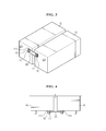
- FIG. 3 is a perspective view schematically showing a combined-configuration of FIG. 2
- FIG. 4 is a view seeing the coupling region of the bus bar shown in FIG. 3 from top to bottom of the battery module.
- the bus bar 20 is coupled with two battery modules therebetween, and thus the battery modules 10 are electrically connected through the bus bar 20.
- the battery modules 10 may have bold-shaped electrode sockets 11 by which the bus bar 20 is coupled together with nuts 12.
- the coupling of the battery modules 10 and the bus bar 20 may be conducted in various forms, and the present invention is not limited to any specific coupling form thereof.
- a pressure sensor 111 may be provided between the bus bar 20 and the battery modules 10.
- the pressure sensor 111 may function as a coupling detection unit 110 for detecting the coupling state of the bus bar 20 to the battery modules 10.
- the bus bar 20 is coupled with the battery modules 10 by means of a coupling member such as nuts, and the pressure sensor 111 may be applied with some extent of pressure in a normal state.
- the pressure sensor 111 may undergo the change of the pressure applied thereto. For example, in the embodiments of FIGs. 3 and 4 , when the nuts 12 become loose, the pressure applied to the pressure sensor 111 is reduced and thus the pressure detected thereby is also decreased.
- the pressure sensor 111 provided in the coupling region between the bus bar 20 and the battery modules 10 may measure a pressure to detect any variation on the coupling state of the bus bar 20.
- the pressure sensor 111 is a thin film-type pressure sensor having a thin thickness.
- the pressure sensor 111 may be interposed between the bus bar 20 and the battery modules 10. Therefore, if the thickness of the pressure sensor 111 is too thick, this may restrict the bus bar 20 to tightly couple to the battery modules 10. Accordingly, it is preferred that the pressure sensor 111 has a thin-film type as thin as paper or an ultra thin film-type.
- the present invention is, however, not limited to any specific type of the pressure sensor 111, and the various types of the pressure sensor may be used.
- the coupling detection unit 110 may also comprise a voltage sensor. That is, the coupling detection unit 110 may measure the voltage change on both ends of the bus bar 20 through the voltage sensor to detect the coupling state of the bus bar 20.
- FIG. 5 schematically shows a configuration for detecting the coupling state of a bus bar 20 by a voltage sensor 112 according to one embodiment of the present invention.
- the voltage sensor 112 is provided on both ends of the bus bar 20 coupled between two battery modules 10, thereby being capable of measuring the current of both ends of the bus bar 20.
- the bus bar 20 In a normal state, the bus bar 20 has a constant resistance and current and it will most likely show no observable voltage change on both ends thereof.
- the resistance of the bus bar 20 may be increased.
- an increase in the resistance of the bus bar 20 means an increase in the voltage of both ends of the bus bar 20 since there will be no changes in the current flow of the bus bar 20. Therefore, the voltage sensor 112 can detect the coupling state of the bus bar to the battery modules 10 by measuring the voltage of both ends of the bus bar 20.
- the detection for the coupling state of the bus bar 20 by means of the coupling detection unit 110 may be continuously or discontinuously conducted.
- the pressure sensor 111 may continuously or periodically detect a pressure applied from the bus bar 20.
- the controlling unit 120 determines the occurrence of a defect in the coupling state of the bus bar 20 on the basis of the results obtained by the coupling detection unit 110, that is, any variation on the coupling state of the bus bar 20 which is detected by means of the coupling detection unit 110.
- the controlling unit 120 may determine the occurrence of a defect in the coupling state of the bus bar 20 when a pressure detected by the pressure sensor 111 is lower than a reference pressure.
- the reference pressure means a pressure value which can be detected by the pressure sensor 111 in the normal coupling state of the bus bar 20 to the battery modules 20.
- the pressure value detected by the pressure may change a bit. Accordingly, the reference pressure may have a value of a certain range, not a specific value.
- the controlling unit 120 may determine the coupling state of the bus bar to have no observable defect when the voltage detected by the pressure sensor 111 is from 10 to 30 kg/cm 2 .
- the bus bar may be determined to have a coupling defect.
- the looseness of the bus bar 20 reduces a pressure applied to the pressure sensor 111, so the controlling unit 120 may determine the coupling state of the bus bar to have a defect on the basis of the looseness.
- the controlling unit 120 comprises a voltage sensor 112 as shown in FIG. 5
- a defect occurrence in the coupling state of the bus bar 20 may be checked by a voltage detected by the voltage sensor 112. That is, the controlling unit 120 can calculate the resistance of the bus bar 20 by using a voltage detected by the voltage sensor 112 and a current flowing through the bus bar 20. At this time, the current flowing through the bus bar 20 may be separately measured through a current sensor, or may be a predetermined value. Then, if the calculated resistance is higher than a reference resistance, the controlling unit 120 may determine a defect in the coupling state of the bus bar by comparing the resistance calculated with the reference resistance.
- the controlling unit 120 may calculate the resistance of the bus bar 20 to be 60 ⁇ (600 V/10 A). Thus, since the resistance calculated of the bus bar 20 is within the range of the reference resistance value, the controlling unit 120 may determine no defect in the coupling state of the bus bar 20 to the battery modules 10. However, if the voltage of both ends of the bus bar 20 is detected to have a 800 V value by the voltage sensor 112, the controlling unit 120 may calculate the resistance of the bus bar 20 to be 80 ⁇ (800 V/10 A). This resistance of the bus bar 20 is higher than the reference value, so the controlling unit 120 may determine a defect in the coupling state of the bus bar 20. This is because the resistance of the bus bar 20 increases if the coupling of the bus bar 20 weakens and becomes loose.
- the controlling unit 120 may also determine whether the coupling state of the bus bar 20 has a defect by comparing the voltage itself of both ends of the bus bar 20 with a reference voltage, although the determination for a coupling defect of the bus bar 20 have been conducted by calculating the resistance of the bus bar 20 from the voltages of both ends of the bus bar 20 and then comparing the resistance calculated with a reference value in the embodiment described above.
- the controlling unit 120 may determine a defect in the coupling state of the bus bar 20 because the resistance change may be estimated on the basis of the voltage change in a constant current.
- Such a controlling unit 120 which determines whether the coupling state of the bus bar has a defect 20 on the basis of the variation of the coupling state detected by the coupling detection unit 110, may comprise a battery management system (BMS).
- BMS battery management system
- the term BMS used herein means a battery managing system provided in a battery pack to control overall charging/discharging operation of the battery.
- the present invention is not limited to such a means for carrying out the controlling unit 120, and the controlling unit 120 may be constructed independent of the BMS.
- the controlling unit 120 determines that the coupling state of the bus bar 20 has a defect, the charge/discharge current of the battery modules 10 may be interrupted to stop the use of the battery pack. If the battery pack is continuously used in the coupling defection state of the bus bar 20, the battery pack may be subject to the performance degradation thereof due to heat generation and, in a severe case, the ignition or explosion thereof. Accordingly, the controlling unit 120 can interrupt the charge/discharge current of the battery modules 10 to stop the use of the battery pack so as to prevent the coupling defect of the bus bar 20 to undergo more severe problems.
- the interruption of the charge/discharge current of the battery modules 10 may be conducted in various manners, for example, by melting a fuse positioned on the charging/discharging path of the battery pack or allowing a charging/discharging switch to be off.
- such a state information may be provided to a user before or after stopping the use of the battery pack.
- the battery pack managing apparatus may further comprise a memory unit 140.
- the memory unit 140 may store all kinds of data necessary for conducting the functions of each component of the battery pack managing apparatus, i.e., a coupling detection unit 110, a controlling unit 120, etc.
- the memory unit 140 may store data on a reference pressure if the coupling defect of the bus bar 20 is determined by the controlling unit 120 on the basis of a pressure detected by the pressure sensor 111.
- the memory unit 140 may store data on a reference voltage or a current flowing in the bus bar 20 if the coupling defect of the bus bar 20 is determined by the controlling unit 120 on the basis of a voltage detected by the voltage sensor 112.
- the battery pack managing apparatus may further comprise a warning unit 130.
- the warning unit 130 informs a user of the coupling defect of the bus bar 20 when the coupling defect of the bus bar 20 is determined by the controlling unit 120.
- the warning unit 130 may have a warning lamp, a display device such as a LCD monitor or a speaker.
- the warning unit 130 may inform a driver of the coupling defect of the bus bar 20 through a LCD monitor and a speaker equipped in a driving seat. Then, the driver can recognize a need for the maintenance, repair and exchange of the battery pack through the warning information and take suitable action.
- the battery pack according to the present invention comprises the battery pack managing apparatus described above. That is, the battery pack may comprise a coupling detection unit 110 for detecting the coupling state of the bus bar and a controlling unit 120 for determining whether the coupling state of the bus bar has a defect on the basis of the coupling state detected by the coupling detection unit 110.
- the battery pack managing apparatus described above is preferably used as a battery pack for electric vehicles.
- the vehicle according to the present invention comprises the battery pack managing apparatus described above.
- the vehicle including the battery pack managing apparatus according to the present invention may be an electric vehicle.
- FIGs. 1 to 5 for the convenience of explanation, two battery modules 10 are shown to be connected to each other. However, battery modules having three or more connections may also be applied in the present invention, which is apparent to those of ordinary skill in the art.
- FIG. 6 is a flow chart schematically illustrating a method for managing a battery pack according to one embodiment of the present invention. Each step of FIG. 6 may be carried out by each component of the battery pack managing apparatus described above.
- step S110 may be conducted by a pressure sensor 111.
- the pressure sensor 111 may be a thin film-type.
- step S110 may be conducted by a voltage sensor 112.
- the bus bar 20 is determined to have a defect or no defect in its coupling state (S120).
- the bus bar 20 may be determined to have a defect in its coupling state in step S120 when a pressure detected by the pressure sensor 111 is lower than a reference pressure value.
- the bus bar 20 may be determined to have a defect in its coupling state in step S120 when the resistance of the bus bar 20, which is calculated from a voltage detected by the voltage sensor 112, is higher than a reference resistance value.
- the battery pack managing method of the present invention may further comprise the step of informing the coupling defect of the bus bar to a user (S130).
- the battery pack managing method may further comprise the step of interrupting the charge/discharge current of the battery modules 10 (S140).
- step S120 may be conducted by a BMS.
- steps of S110 to S140 are preferably applied in a battery pack for vehicles.
- the term 'unit' used herein just represents a logic unit, which may not be a component that can be physically separated, which is apparent to those of ordinary skill in the art.
Landscapes
- Chemical & Material Sciences (AREA)
- Chemical Kinetics & Catalysis (AREA)
- Electrochemistry (AREA)
- General Chemical & Material Sciences (AREA)
- Engineering & Computer Science (AREA)
- Manufacturing & Machinery (AREA)
- Physics & Mathematics (AREA)
- General Physics & Mathematics (AREA)
- Inorganic Chemistry (AREA)
- Secondary Cells (AREA)
- Battery Mounting, Suspending (AREA)
- Connection Of Batteries Or Terminals (AREA)
- Charge And Discharge Circuits For Batteries Or The Like (AREA)
Applications Claiming Priority (2)
| Application Number | Priority Date | Filing Date | Title |
|---|---|---|---|
| KR1020110001688A KR101310733B1 (ko) | 2011-01-07 | 2011-01-07 | 배터리 팩 관리 장치 및 방법 |
| PCT/KR2011/009953 WO2012093788A2 (ko) | 2011-01-07 | 2011-12-21 | 배터리 팩 관리 장치 및 방법 |
Publications (2)
| Publication Number | Publication Date |
|---|---|
| EP2642558A2 true EP2642558A2 (de) | 2013-09-25 |
| EP2642558A4 EP2642558A4 (de) | 2016-11-30 |
Family
ID=46457795
Family Applications (1)
| Application Number | Title | Priority Date | Filing Date |
|---|---|---|---|
| EP11854846.0A Ceased EP2642558A4 (de) | 2011-01-07 | 2011-12-21 | Verfahren und vorrichtung zur verwaltung von batteriepaketen |
Country Status (6)
| Country | Link |
|---|---|
| US (1) | US9112216B2 (de) |
| EP (1) | EP2642558A4 (de) |
| JP (1) | JP5997178B2 (de) |
| KR (1) | KR101310733B1 (de) |
| CN (1) | CN103283062B (de) |
| WO (1) | WO2012093788A2 (de) |
Cited By (1)
| Publication number | Priority date | Publication date | Assignee | Title |
|---|---|---|---|---|
| FR3097970A1 (fr) * | 2019-06-27 | 2021-01-01 | Airbus Helicopters | Architecture électrique munie d’un système de surveillance d’au moins une connexion électrique d’un réseau électrique, véhicule et procédé |
Families Citing this family (33)
| Publication number | Priority date | Publication date | Assignee | Title |
|---|---|---|---|---|
| JP5935744B2 (ja) * | 2013-04-02 | 2016-06-15 | トヨタ自動車株式会社 | 検出装置及び検出方法 |
| US9935342B2 (en) | 2013-08-15 | 2018-04-03 | Robert Bosch Gmbh | Li/metal battery with shape change control |
| JP6442822B2 (ja) * | 2013-10-01 | 2018-12-26 | 株式会社Gsユアサ | 異常判定装置 |
| JP6156035B2 (ja) * | 2013-10-01 | 2017-07-05 | 株式会社豊田自動織機 | 蓄電モジュールの異常検出方法及び異常検出装置 |
| KR20160071424A (ko) * | 2013-10-16 | 2016-06-21 | 알리스 에코 에이알케이 코. 엘티디. | 전기 자동차의 배터리 접촉을 위한 확동 고정 확인 방법즘 |
| JP6262338B2 (ja) * | 2013-10-16 | 2018-01-17 | アリース エコ アーク(ケイマン) シーオー.エルティーディー. | 電気自動車のバッテリの接触に対する固定状態確認機構及びバッテリパックの電極に対する固定状態確認デバイス |
| EP3059797B1 (de) * | 2013-10-16 | 2020-04-01 | Aleees Eco Ark (Cayman) Co. LTD. | Nachweisvorrichtung zur erkennung des sperrstatus mehrerer elektroden durch verwendung eines batteriesensors |
| US9573484B2 (en) * | 2014-01-24 | 2017-02-21 | GM Global Technology Operations LLC | Systems and methods for determining battery state information based on internal battery pressure |
| JP6409389B2 (ja) * | 2014-07-28 | 2018-10-24 | 株式会社豊田自動織機 | 蓄電装置の異常検出方法及び蓄電装置の異常検出装置 |
| DE102015201920A1 (de) * | 2015-02-04 | 2016-08-04 | Bayerische Motoren Werke Aktiengesellschaft | Verfahren zum Messen eines Übergangswiderstandes |
| US10151789B2 (en) | 2015-02-09 | 2018-12-11 | Acculogic Corporation | Method and device for testing the connections of batteries |
| KR20160123173A (ko) * | 2015-04-15 | 2016-10-25 | 삼성전자주식회사 | 부스바의 연결 상태 판단 장치 및 방법 |
| JP6582612B2 (ja) * | 2015-06-25 | 2019-10-02 | 株式会社豊田自動織機 | 電池モジュール |
| KR102032503B1 (ko) * | 2015-11-05 | 2019-10-15 | 주식회사 엘지화학 | 배터리 모듈, 이러한 배터리 모듈을 포함하는 배터리 팩 및 이러한 배터리 팩을 포함하는 자동차 |
| KR102345507B1 (ko) * | 2017-01-24 | 2021-12-29 | 삼성에스디아이 주식회사 | 배터리 팩 및 배터리 팩이 연결된 차량 |
| CN106938618B (zh) * | 2017-04-11 | 2018-11-30 | 绵阳旭立辰科技有限公司 | 采用具备预警功能的电动车充电机系统进行预警的方法 |
| KR102207054B1 (ko) * | 2017-12-04 | 2021-01-25 | 에스케이이노베이션 주식회사 | 배터리 모듈 연결 진단 장치 |
| US10641835B2 (en) * | 2018-03-15 | 2020-05-05 | Ascending Energy Inc. | Health monitoring and safety protection for lithium ion battery modules and applications |
| US11703547B2 (en) * | 2018-04-03 | 2023-07-18 | Maxim Integrated Products, Inc. | Software-configurable battery management systems and methods |
| KR102627843B1 (ko) * | 2018-09-10 | 2024-01-19 | 주식회사 엘지에너지솔루션 | 배터리 관리 장치 |
| US10978751B2 (en) | 2019-03-13 | 2021-04-13 | Lg Chem, Ltd. | Battery system |
| JP7235553B2 (ja) * | 2019-03-26 | 2023-03-08 | 株式会社Subaru | 車載用バッテリの異常検出装置 |
| KR102718122B1 (ko) | 2019-05-02 | 2024-10-15 | 주식회사 엘지에너지솔루션 | 전도체의 불량을 검출하기 위한 장치, 방법 및 배터리 팩 |
| CN113820616A (zh) * | 2020-06-02 | 2021-12-21 | 广州汽车集团股份有限公司 | 电池监控方法、系统、电池管理系统和车辆 |
| KR102807492B1 (ko) | 2020-10-12 | 2025-05-13 | 주식회사 엘지에너지솔루션 | 배터리 장치, 배터리 관리 시스템 및 연결 상태 진단 방법 |
| KR102888277B1 (ko) | 2021-01-21 | 2025-11-18 | 주식회사 엘지에너지솔루션 | 버스바 진단 장치, 배터리 팩, 에너지 저장 시스템 및 버스바 진단 방법 |
| KR20220106376A (ko) * | 2021-01-22 | 2022-07-29 | 주식회사 엘지에너지솔루션 | 전지 모듈 및 이를 포함하는 전지 팩 |
| CN113960500B (zh) * | 2021-08-24 | 2024-03-22 | 欣旺达电子股份有限公司 | 一种检测电路、检测系统及检测方法 |
| KR102662647B1 (ko) * | 2021-09-09 | 2024-05-03 | 에스케이온 주식회사 | 배터리 팩 |
| US11955667B2 (en) * | 2021-11-15 | 2024-04-09 | Beta Air, Llc | System and method for a battery assembly |
| EP4184190A1 (de) * | 2021-11-23 | 2023-05-24 | Hilti Aktiengesellschaft | Verfahren zum bestimmen der konduktivität eines elektrischen leiters zwischen einer erster systemkomponente und einer zweiten systemkomponente |
| JP7525462B2 (ja) * | 2021-11-29 | 2024-07-30 | プライムプラネットエナジー&ソリューションズ株式会社 | 電池モジュール |
| KR20240039249A (ko) | 2022-09-19 | 2024-03-26 | 주식회사 엘지에너지솔루션 | 이방성 도전필림을 활용한 버스바의 볼트와 너트 체결체 및 체결 방법 |
Family Cites Families (12)
| Publication number | Priority date | Publication date | Assignee | Title |
|---|---|---|---|---|
| JPH09199107A (ja) * | 1996-01-12 | 1997-07-31 | Nissan Motor Co Ltd | バッテリ端子部面圧不良防止装置および同防止方法 |
| JP3365602B2 (ja) * | 1996-05-09 | 2003-01-14 | トヨタ自動車株式会社 | 電気自動車の電池出力の制御方法とそれに用いられる電池の端子接続構造 |
| US6133709A (en) * | 1997-01-21 | 2000-10-17 | Metrixx Limited | Signalling system |
| JP2003123734A (ja) | 2001-10-16 | 2003-04-25 | Auto Network Gijutsu Kenkyusho:Kk | バッテリー端子とバスバーの接続構造 |
| JP2004265840A (ja) | 2003-03-04 | 2004-09-24 | Fuji Heavy Ind Ltd | バッテリの端子接続構造 |
| JP2007513459A (ja) * | 2003-08-11 | 2007-05-24 | リザーブ パワー セル,エルエルシー | 複数電池システム、複数電池管理システム、補助電池付帯システム、及び回線制御された複数電池システム |
| US7339347B2 (en) | 2003-08-11 | 2008-03-04 | Reserve Power Cell, Llc | Apparatus and method for reliably supplying electrical energy to an electrical system |
| DE102004031601A1 (de) * | 2004-06-30 | 2006-02-09 | Hilti Ag | Akkupack für Elektrohandwerkzeugmaschine |
| JP2007147689A (ja) * | 2005-11-24 | 2007-06-14 | Fuji Xerox Co Ltd | 加熱装置および画像形成装置 |
| JP2008241421A (ja) * | 2007-03-27 | 2008-10-09 | Toyota Motor Corp | 締結部材の状態を検出する検出装置、その検出装置を備えた蓄電機構 |
| KR100897091B1 (ko) * | 2007-05-21 | 2009-05-14 | 현대자동차주식회사 | 회전방지 구조를 갖는 고전압 배터리용 배터리모듈 단자와버스바 |
| JP4696291B2 (ja) * | 2009-06-04 | 2011-06-08 | 三菱自動車工業株式会社 | 二次電池異常検出装置 |
-
2011
- 2011-01-07 KR KR1020110001688A patent/KR101310733B1/ko active Active
- 2011-12-21 WO PCT/KR2011/009953 patent/WO2012093788A2/ko not_active Ceased
- 2011-12-21 JP JP2013548338A patent/JP5997178B2/ja active Active
- 2011-12-21 CN CN201180064353.2A patent/CN103283062B/zh active Active
- 2011-12-21 EP EP11854846.0A patent/EP2642558A4/de not_active Ceased
-
2012
- 2012-07-18 US US13/552,116 patent/US9112216B2/en active Active
Cited By (1)
| Publication number | Priority date | Publication date | Assignee | Title |
|---|---|---|---|---|
| FR3097970A1 (fr) * | 2019-06-27 | 2021-01-01 | Airbus Helicopters | Architecture électrique munie d’un système de surveillance d’au moins une connexion électrique d’un réseau électrique, véhicule et procédé |
Also Published As
| Publication number | Publication date |
|---|---|
| JP2014507757A (ja) | 2014-03-27 |
| EP2642558A4 (de) | 2016-11-30 |
| US9112216B2 (en) | 2015-08-18 |
| CN103283062A (zh) | 2013-09-04 |
| KR101310733B1 (ko) | 2013-09-24 |
| WO2012093788A3 (ko) | 2012-09-20 |
| US20120280692A1 (en) | 2012-11-08 |
| JP5997178B2 (ja) | 2016-09-28 |
| WO2012093788A2 (ko) | 2012-07-12 |
| KR20120080315A (ko) | 2012-07-17 |
| CN103283062B (zh) | 2016-01-20 |
Similar Documents
| Publication | Publication Date | Title |
|---|---|---|
| US9112216B2 (en) | Apparatus and method for managing battery pack | |
| EP2521213B1 (de) | Vorrichtung und verfahren zur verwaltung eines batteriepacks | |
| JP4001708B2 (ja) | 二次電池の交換方法 | |
| US9059486B2 (en) | Automatic crash battery discharge method | |
| US20120169117A1 (en) | Battery system and electric vehicle including the same | |
| US10158237B2 (en) | Battery pack and electric bike including the same | |
| US10124693B2 (en) | Battery pack and electric vehicle including the same | |
| US20110037476A1 (en) | Method and apparatus for detecting abnormality of current sensor in battery pack | |
| KR20130137389A (ko) | 배터리 팩의 전류센서 이상 진단 장치 및 방법 | |
| KR101475917B1 (ko) | 배터리 팩 보호 장치 및 이를 포함하는 배터리 팩 | |
| JP2011150876A (ja) | 組電池および組電池の制御方法 | |
| KR20140055065A (ko) | 배터리 팩 관리 장치 및 방법 | |
| EP3093946B1 (de) | Elektrische übertragungsvorrichtung und steuerungsverfahren dafür | |
| TWI849038B (zh) | 電池管理裝置及方法以及電池組 | |
| JP2020038812A (ja) | 二次電池の再利用方法、管理装置、及びコンピュータプログラム | |
| US20140186665A1 (en) | Battery system | |
| KR20140020660A (ko) | 배터리 모듈 검사장치 | |
| US20160141729A1 (en) | Protection apparatus for rechargeable battery and protection method for rechargeable battery using the same | |
| JP4553853B2 (ja) | 車両用の電源装置 | |
| Maruno et al. | Battery Control Technology of Li-Ion Battery System for HEV |
Legal Events
| Date | Code | Title | Description |
|---|---|---|---|
| PUAI | Public reference made under article 153(3) epc to a published international application that has entered the european phase |
Free format text: ORIGINAL CODE: 0009012 |
|
| 17P | Request for examination filed |
Effective date: 20130619 |
|
| AK | Designated contracting states |
Kind code of ref document: A2 Designated state(s): AL AT BE BG CH CY CZ DE DK EE ES FI FR GB GR HR HU IE IS IT LI LT LU LV MC MK MT NL NO PL PT RO RS SE SI SK SM TR |
|
| DAX | Request for extension of the european patent (deleted) | ||
| A4 | Supplementary search report drawn up and despatched |
Effective date: 20161103 |
|
| RIC1 | Information provided on ipc code assigned before grant |
Ipc: H01M 10/42 20060101ALI20161027BHEP Ipc: H01M 2/20 20060101AFI20161027BHEP Ipc: H01M 10/052 20100101ALI20161027BHEP Ipc: H01M 10/48 20060101ALI20161027BHEP Ipc: G01R 31/36 20060101ALI20161027BHEP Ipc: G01R 31/02 20060101ALI20161027BHEP Ipc: H01M 2/10 20060101ALI20161027BHEP |
|
| RAP1 | Party data changed (applicant data changed or rights of an application transferred) |
Owner name: LG CHEM, LTD. |
|
| STAA | Information on the status of an ep patent application or granted ep patent |
Free format text: STATUS: EXAMINATION IS IN PROGRESS |
|
| 17Q | First examination report despatched |
Effective date: 20191018 |
|
| RAP1 | Party data changed (applicant data changed or rights of an application transferred) |
Owner name: LG ENERGY SOLUTION LTD. |
|
| RAP3 | Party data changed (applicant data changed or rights of an application transferred) |
Owner name: LG ENERGY SOLUTION, LTD. |
|
| APBK | Appeal reference recorded |
Free format text: ORIGINAL CODE: EPIDOSNREFNE |
|
| APBN | Date of receipt of notice of appeal recorded |
Free format text: ORIGINAL CODE: EPIDOSNNOA2E |
|
| APAF | Appeal reference modified |
Free format text: ORIGINAL CODE: EPIDOSCREFNE |
|
| APBR | Date of receipt of statement of grounds of appeal recorded |
Free format text: ORIGINAL CODE: EPIDOSNNOA3E |
|
| APAF | Appeal reference modified |
Free format text: ORIGINAL CODE: EPIDOSCREFNE |
|
| REG | Reference to a national code |
Ref country code: DE Ref legal event code: R003 |
|
| APBT | Appeal procedure closed |
Free format text: ORIGINAL CODE: EPIDOSNNOA9E |
|
| STAA | Information on the status of an ep patent application or granted ep patent |
Free format text: STATUS: THE APPLICATION HAS BEEN REFUSED |
|
| 18R | Application refused |
Effective date: 20260123 |