EP2642501A2 - Hochspannungs-Gleichstrom-Leistungsschalteranordnung und Verfahren - Google Patents
Hochspannungs-Gleichstrom-Leistungsschalteranordnung und Verfahren Download PDFInfo
- Publication number
- EP2642501A2 EP2642501A2 EP13172435.3A EP13172435A EP2642501A2 EP 2642501 A2 EP2642501 A2 EP 2642501A2 EP 13172435 A EP13172435 A EP 13172435A EP 2642501 A2 EP2642501 A2 EP 2642501A2
- Authority
- EP
- European Patent Office
- Prior art keywords
- current
- circuit breaker
- direct current
- circuit
- line
- Prior art date
- Legal status (The legal status is an assumption and is not a legal conclusion. Google has not performed a legal analysis and makes no representation as to the accuracy of the status listed.)
- Granted
Links
Images

Classifications
-
- H—ELECTRICITY
- H01—ELECTRIC ELEMENTS
- H01H—ELECTRIC SWITCHES; RELAYS; SELECTORS; EMERGENCY PROTECTIVE DEVICES
- H01H33/00—High-tension or heavy-current switches with arc-extinguishing or arc-preventing means
- H01H33/02—Details
- H01H33/59—Circuit arrangements not adapted to a particular application of the switch and not otherwise provided for, e.g. for ensuring operation of the switch at a predetermined point in the AC cycle
-
- H—ELECTRICITY
- H01—ELECTRIC ELEMENTS
- H01H—ELECTRIC SWITCHES; RELAYS; SELECTORS; EMERGENCY PROTECTIVE DEVICES
- H01H33/00—High-tension or heavy-current switches with arc-extinguishing or arc-preventing means
- H01H33/02—Details
-
- H—ELECTRICITY
- H01—ELECTRIC ELEMENTS
- H01H—ELECTRIC SWITCHES; RELAYS; SELECTORS; EMERGENCY PROTECTIVE DEVICES
- H01H33/00—High-tension or heavy-current switches with arc-extinguishing or arc-preventing means
- H01H33/02—Details
- H01H33/59—Circuit arrangements not adapted to a particular application of the switch and not otherwise provided for, e.g. for ensuring operation of the switch at a predetermined point in the AC cycle
- H01H33/596—Circuit arrangements not adapted to a particular application of the switch and not otherwise provided for, e.g. for ensuring operation of the switch at a predetermined point in the AC cycle for interrupting DC
-
- H—ELECTRICITY
- H03—ELECTRONIC CIRCUITRY
- H03K—PULSE TECHNIQUE
- H03K17/00—Electronic switching or gating, i.e. not by contact-making and –breaking
- H03K17/51—Electronic switching or gating, i.e. not by contact-making and –breaking characterised by the components used
- H03K17/56—Electronic switching or gating, i.e. not by contact-making and –breaking characterised by the components used by the use, as active elements, of semiconductor devices
- H03K17/72—Electronic switching or gating, i.e. not by contact-making and –breaking characterised by the components used by the use, as active elements, of semiconductor devices having more than two PN junctions; having more than three electrodes; having more than one electrode connected to the same conductivity region
- H03K17/73—Electronic switching or gating, i.e. not by contact-making and –breaking characterised by the components used by the use, as active elements, of semiconductor devices having more than two PN junctions; having more than three electrodes; having more than one electrode connected to the same conductivity region for DC voltages or currents
-
- H—ELECTRICITY
- H01—ELECTRIC ELEMENTS
- H01H—ELECTRIC SWITCHES; RELAYS; SELECTORS; EMERGENCY PROTECTIVE DEVICES
- H01H33/00—High-tension or heavy-current switches with arc-extinguishing or arc-preventing means
- H01H33/02—Details
- H01H33/04—Means for extinguishing or preventing arc between current-carrying parts
- H01H33/14—Multiple main contacts for the purpose of dividing the current through, or potential drop along, the arc
Definitions
- the invention relates generally to the field of electrical power transmission systems and in particular to means for interrupting or commutating a high voltage direct current.
- the invention also relates to a corresponding method.
- High voltage direct current (HVDC) power systems comprise protection and control systems arranged to protect, monitor and control the functioning of devices forming part of the power system.
- the protection systems prevent, among other things, short-circuits, over-currents and over-voltages in e.g. power transmission lines of the HVDC system.
- Protective relays are used throughout the HVDC system for providing such protection and control.
- the protective relays detect and isolate faults on transmission and distribution lines by opening and closing circuit breakers. It is not always necessary to perform a complete interruption; instead a commutation to an alternative path is performed. In essence the current in part(s) of the original current path will stop flowing, but it will not be interrupted, only redirected. To achieve this, a HVDC breaker is used.
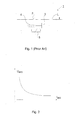
- FIG. 1 illustrates schematically a basic conventional direct current (DC) circuit breaker, also called DC breaker, which is arranged along a DC line L carrying a direct current I.
- the DC breaker 1 is designed so as to be able to break or commutate the direct current I.
- the DC breaker 1 comprises an alternating current circuit breaker 2, denoted interrupter in the following, connected in parallel with a resonant LC branch 3, 4, i.e. a capacitor 3 connected in series with an inductor 4.
- a non-linear resistor 5 is connected in parallel with the LC branch 3, 4 for limiting the capacitor voltage when the direct current I flows through the capacitor instead of through the interrupter 2.
- the inductor 4 may, but needs not to, be a physical component; the leakage inductance in the circuit can often be enough.
- FIG. 1 illustrates the arc characteristics of the arc current I arc in the interrupter 2.
- I arc up to approximately 5 kA the arc voltage/current slope is negative, which causes a growing oscillation against the LC branch 3, 4.
- the oscillating current has grown enough, i.e. so as to be equal to the direct current I, the arc current I arc reaches a current zero crossing, whereupon the arc is extinguished and the total direct current goes through the capacitor 3.
- the voltage of the capacitor 3 then grows rapidly until it reaches the knee point of the non-linear resistor 5, e.g. a surge arrester, which is arranged to limit the voltage on the capacitor 3.
- the capacitor voltage constitutes a counter-voltage in the circuit causing the current I to decrease until it ceases.
- a DC circuit breaker arrangement for interrupting a direct current on a line
- the line is to be understood as either a power transmission line or a connection line in a HVDC circuit carrying the direct current to be interrupted.
- the DC circuit breaker arrangement comprises at least a first and a second DC breaker arranged in parallel along the line and the current of the line is divided between the at least first and second DC breakers.
- the DC circuit breaker arrangement comprises a first DC breaker, which in turn comprises a first interrupter connected to the line.
- the first DC breaker further comprises a first resonant LC branch and a first non-linear resistor connected in parallel with the first interrupter.
- the DC circuit breaker arrangement comprises further a second DC breaker, identical to the first DC breaker.
- the second DC breaker thus comprises a second interrupter and a second resonant LC branch and a second non-linear resistor connected in parallel with the second interrupter.
- the second DC breaker is connected in parallel with the first DC breaker on the line, where the parallel connection of first and second DC breaker is connected in series with the line.
- the direct current is divided between the first and second DC breakers.
- each branch carrying a part of the current By introducing a division of the current into two or more branches, each branch carrying a part of the current, the steady state current in each interrupter is halved or lessened even more. Further, the current to be interrupted in each interrupter is also halved or lessened even more.
- a DC circuit breaker arrangement is provided, able to handle direct currents up to 10 kA or even higher.
- the DC circuit breaker arrangement can be made by using conventional components that are readily available, rendering the DC circuit breaker arrangement cost-efficient and easy to manufacture.
- a DC circuit breaker arrangement is provided for use in applications wherein the nominal direct current or currents during overload conditions exceed the capacity of existing DC breakers.
- means are included for preserving the desired current division during an interruption process of the at least first and second DC breakers.
- a most reliable DC circuit breaker arrangement is thus provided, wherein there is no risk of the circuit breaker that interrupts its current first commutating the full current to the other circuit breaker.
- the means for preserving the current division during the interruption process comprises a two winding transformer connected to the first and second DC breakers.
- the invention can thus be implemented using conventional components, enabling a cost-efficient solution.
- a third DC breaker is provided connected in parallel with the first and second DC breakers on the transmission line or in the HVDC circuit.
- the current is thus divided between three branches and a DC circuit breaker arrangement able to handle even higher currents is thereby provided.
- Such circuit breaker arrangement is sufficient for all types of applications of a high voltage direct current (HVDC) network.
- the means for enabling a preserved current distribution during the interruption process with three branches comprises three Z-connected (zig-zag-connected) transformers which are connected to the first, second and third DC breakers.
- the invention can be implemented using conventional components, which enables a cost-efficient solution.
- the invention is also related to a corresponding method, whereby advantages similar to the above are achieved.
- FIG. 3 illustrates a first embodiment of the invention.
- a DC circuit breaker arrangement in the following denoted DC circuit breaker arrangement 6, in accordance with the invention, is arranged connected along, i.e. in series with, a line L carrying a dc current I.
- the line L can be a power transmission line or a connection line in a HVDC circuit.
- the direct current I of the line L is divided into two branches B1 and B2.
- the two branches B1, B2 are identical, and each comprises a DC breaker 1 1 , 1 2 , which in turn comprises a respective first or second interrupter 2 1 , 2 2 as described in connection with figure 1 .
- Respective first or second LC branches 3 1 , 4 1 and 3 2 , 4 2 are connected in parallel with the respective first or second interrupter 2 1 , 2 2 .
- first and second non-linear resistors 5 1 and 5 2 are connected in parallel with the respective first or second LC branches 3 1 , 4 1 ; 3 2 , 4 2 .
- Each branch B1, B2 thus takes half the line current I.
- a two winding transformer T1 is used in accordance with the invention.
- the magnetizing impedance of the two winding transformer T1 opposes an uneven current distribution that would occur in the above-described situation, when the one of the first and the second interrupters 2 1 and 2 2 has successfully interrupted its current.
- the DC circuit breaker arrangement 6 in accordance with the first embodiment of the invention thus comprises two parallel-connected conventional DC breakers 1 1 and 1 2 connected to a two winding transformer T1, i.e. to a single-phase two-winding transformer comprising primary and secondary windings, or coils, wound around a single magnetic core.
- one of the DC breakers 1 1 and 1 2 is connected to the polarity end of one winding of the transformer T1
- the other DC breaker is connected to the non-polarity end of the other winding of the transformer T1.
- the winding polarities are shown in the figure by filled-in dots, in conventional manner. During steady state operation, the currents of the windings will cancel out the magnetic flux of each other in the core. Conventional components can thus be utilized, providing a cost-efficient DC circuit breaker arrangement.
- the DC breakers 1 1 , 1 2 work in conventional manner, as described in the introductory part of the present application.
- One of the DC breakers 1 1 , 1 2 will succeed first in the current interruption process.
- the one first succeeding is denoted x and its current will flow through its associated capacitor 3 x .
- the voltage across the DC breaker 1 x will grow and this voltage will try to move the current in branch Bx to the other branch, which still has no counter-voltage.
- the magnetizing impedance of the transformer T1 prevents this from happening.
- FIG. 4 illustrates a second embodiment of the invention.
- the direct current I is divided into three branches B1, B2 and B3, each branch thus carrying a third of the direct current I during steady state operation.
- Each branch B1, B2, B3 comprises a respective DC breaker 1 1 , 1 2 , 1 3 with a layout as described earlier.
- transformers T1, T2, T3 are provided.
- the transformers T1, T2, T3 are connected in a zig-zag connection with the polarities as indicated in the figure 4 .
- this transformer connection is also known as Z-connection, and could be achieved with a three-phase Z-connected transformer.
- the non-polarity terminal of one coil on each transformer is connected to the non-polarity terminal of one coil in another transformer.
- the connection can be so that the polarity terminal of one coil on each transformer is connected to the polarity terminal of one coil of another transformer.
- the mutual inductance of the transformers functions to preserve the current distribution during the interruption process.
- the leakage inductance of the transformer(s) will be added to the inductance of the total circuit, since all current derivatives will be in the same direction.
- the leakage inductance, also known as short circuit impedance, of a transformer is very low, several thousands times lower than the magnetizing inductance and can be neglected.
- the principles of the invention may be applied in a corresponding manner to any number n of branches B1, B2 ..., Bn.
- the DC circuit breaker arrangement 6 n-1 can thus be designed and adapted for each specific application.
- the above-described DC circuit breaker arrangement 6' having three branches B1, B2, B3 is adequate for most applications that can be foreseen in the near future.
- a number of more cost-efficient DC circuit breakers able to handle much lower currents e.g. 500 A, can be used, applying the principles of the invention.
- n of transformers is utilized in order to preserve the current division during an interruption process of the interrupters 2 1 , 2 2 , ..., 2 n .
- other means for preserving the current distribution between the different branches could be used instead.
- a device comprising only reactors without relying on the above-described mutual inductance could, for example, alternatively be used.
- considerations would have to be made regarding the fact that the very large inductance needed for preserving current distribution during interruption would remain in the circuit even after the interrupters in all branches have succeeded in commutating the current to their respective capacitors or non-linear resistors.
- the invention also provides a method 10 for interrupting or commutating a direct current I on a transmission line L or HVDC circuit, as depicted in figure 5 .
- the method 10 comprises a first step 11 of dividing the direct current I into two or more branches B1, B2, B3.
- a second step 12 comprises interrupting the direct current I by actuating DC breakers 1 1 , 1 2 , 1 3 arranged at each respective branch B1, B2, B3, while preserving, by means of a transformer arrangement, the current division during interruption of the direct current I.
- the DC breakers 1 1 , 1 2 , 1 3 are arranged as described earlier, as is the transformer arrangement, i.e.
- the transformer arrangement is one single-phase two winding transformer T1 if the current is divided into two branches, or three two winding transformers T1, T2, T3 if the current is divided into three branches, and so on, n two-winding transformers T1, T2, T3,..., Tn for dividing the current into n branches.
- the present invention provides means for permitting the interruption of direct currents above 5 kA, most advantageously at 10 kA or even higher by combining conventional DC breakers having interrupters able to handle up to about 5 kA.
- the invention is thus advantageous for applications in which the current exceeds 5 kA, be it in nominal current or during overload conditions.
- the steady state current in each interrupter is halved or even better.
- the current to be interrupted (or to oscillate at) is halved or better.
- an even current distribution is forced in steady state and transiently in an innovative manner.
Landscapes
- Engineering & Computer Science (AREA)
- Power Engineering (AREA)
- Driving Mechanisms And Operating Circuits Of Arc-Extinguishing High-Tension Switches (AREA)
Priority Applications (1)
| Application Number | Priority Date | Filing Date | Title |
|---|---|---|---|
| EP13172435.3A EP2642501B1 (de) | 2008-11-26 | 2008-11-26 | Hochspannungs-Gleichstrom-Leistungsschalteranordnung und Verfahren |
Applications Claiming Priority (3)
| Application Number | Priority Date | Filing Date | Title |
|---|---|---|---|
| PCT/EP2008/066243 WO2010060476A1 (en) | 2008-11-26 | 2008-11-26 | High voltage direct current circuit breaker arrangement and method |
| EP13172435.3A EP2642501B1 (de) | 2008-11-26 | 2008-11-26 | Hochspannungs-Gleichstrom-Leistungsschalteranordnung und Verfahren |
| EP08875377.7A EP2370983B1 (de) | 2008-11-26 | 2008-11-26 | Hochspannungs-gleichstrom-unterbrecherschalteranordnung und verfahren |
Related Parent Applications (2)
| Application Number | Title | Priority Date | Filing Date |
|---|---|---|---|
| EP08875377.7A Division EP2370983B1 (de) | 2008-11-26 | 2008-11-26 | Hochspannungs-gleichstrom-unterbrecherschalteranordnung und verfahren |
| EP08875377.7 Division | 2008-11-26 |
Publications (3)
| Publication Number | Publication Date |
|---|---|
| EP2642501A2 true EP2642501A2 (de) | 2013-09-25 |
| EP2642501A3 EP2642501A3 (de) | 2014-03-19 |
| EP2642501B1 EP2642501B1 (de) | 2019-10-23 |
Family
ID=40874765
Family Applications (2)
| Application Number | Title | Priority Date | Filing Date |
|---|---|---|---|
| EP13172435.3A Active EP2642501B1 (de) | 2008-11-26 | 2008-11-26 | Hochspannungs-Gleichstrom-Leistungsschalteranordnung und Verfahren |
| EP08875377.7A Active EP2370983B1 (de) | 2008-11-26 | 2008-11-26 | Hochspannungs-gleichstrom-unterbrecherschalteranordnung und verfahren |
Family Applications After (1)
| Application Number | Title | Priority Date | Filing Date |
|---|---|---|---|
| EP08875377.7A Active EP2370983B1 (de) | 2008-11-26 | 2008-11-26 | Hochspannungs-gleichstrom-unterbrecherschalteranordnung und verfahren |
Country Status (7)
| Country | Link |
|---|---|
| US (2) | US8797695B2 (de) |
| EP (2) | EP2642501B1 (de) |
| KR (1) | KR101183506B1 (de) |
| CN (1) | CN102227796B (de) |
| DK (1) | DK2370983T3 (de) |
| ES (1) | ES2428001T3 (de) |
| WO (1) | WO2010060476A1 (de) |
Families Citing this family (14)
| Publication number | Priority date | Publication date | Assignee | Title |
|---|---|---|---|---|
| EP2494571B1 (de) * | 2009-10-27 | 2013-12-11 | ABB Technology AG | Hochspannungs-gleichstrom-schutzschalter und steuervorrichtung für einen hochspannungs-gleichstrom-schutzschalter |
| EP2469552B1 (de) * | 2010-12-23 | 2014-02-26 | ABB Technology AG | Verfahren, Schutzschalter und Schalteinheit zum Abschalten von Hochspannungsgleichströmen |
| EP2632040A1 (de) * | 2012-02-24 | 2013-08-28 | ABB Technology Ltd | Transformatoranordnung für eine Kurzkupplung |
| WO2013127463A1 (en) * | 2012-03-01 | 2013-09-06 | Alstom Technology Ltd | High voltage dc circuit breaker apparatus |
| CN104620345B (zh) * | 2012-08-27 | 2016-10-26 | Abb瑞士股份有限公司 | 布置用于断开电流的装置 |
| CN103280763B (zh) * | 2013-02-27 | 2016-12-28 | 国网智能电网研究院 | 一种直流断路器及其实现方法 |
| US9871437B2 (en) | 2014-07-10 | 2018-01-16 | University-Industry Foundation(UIF) | Fault current reduction structure of multi-level converter and apparatus using the fault current reduction structure |
| CN106505514B (zh) * | 2016-11-11 | 2019-02-01 | 西安交通大学 | 磁感应转移和电阻限流相结合的直流断路器及其使用方法 |
| EP3336868B1 (de) * | 2016-12-15 | 2023-05-17 | General Electric Technology GmbH | Schaltgerät |
| EP3340409B1 (de) * | 2016-12-23 | 2019-08-14 | ABB Schweiz AG | Induktiver elementschutz in einem stromversorgungssystem |
| JP7018959B2 (ja) * | 2017-11-09 | 2022-02-14 | 三菱電機株式会社 | 直流遮断装置 |
| CN108052705B (zh) * | 2017-11-27 | 2023-07-21 | 中电普瑞电力工程有限公司 | 基于电流分解和绕组等效的变压器电磁转换方法和装置 |
| FR3076127B1 (fr) * | 2017-12-22 | 2020-01-03 | Commissariat A L'energie Atomique Et Aux Energies Alternatives | Pvt detection circuit |
| CN109935479A (zh) * | 2019-04-23 | 2019-06-25 | 西安交通大学 | 基于真空磁吹转移的直流断路器及其开断方法 |
Family Cites Families (14)
| Publication number | Priority date | Publication date | Assignee | Title |
|---|---|---|---|---|
| FR1199633A (fr) * | 1958-04-23 | 1959-12-15 | Merlin Gerin | Perfectionnement à l'interruption des courants électriques |
| US3678338A (en) * | 1971-02-25 | 1972-07-18 | Robert W Beachley | Protective automatically disconnectable grouping means for an ungrounded a.c. electrical distribution system |
| FR2166440A5 (de) * | 1971-11-05 | 1973-08-17 | Comp Generale Electricite | |
| US4305107A (en) * | 1977-09-02 | 1981-12-08 | Tokyo Shibaura Denki Kabushiki Kaisha | DC Interrupting apparatus |
| JPS54153368U (de) * | 1978-04-19 | 1979-10-25 | ||
| JPS56158034U (de) * | 1980-04-25 | 1981-11-25 | ||
| JPS56158034A (en) | 1980-05-09 | 1981-12-05 | Matsuyama Kk | Method and apparatus for recovering agricultural sheet |
| JPS5759217A (en) * | 1980-09-26 | 1982-04-09 | Chuo Seisakusho:Kk | Direct-current feeding device |
| JP2645045B2 (ja) * | 1987-12-28 | 1997-08-25 | 株式会社東芝 | 電力変換装置 |
| SE9403209L (sv) * | 1994-09-23 | 1996-03-24 | Asea Brown Boveri | Seriekompenserad strömriktarstation |
| JPH0950743A (ja) * | 1995-08-08 | 1997-02-18 | Mitsubishi Electric Corp | 直流遮断装置 |
| JP3674419B2 (ja) * | 1999-11-17 | 2005-07-20 | 株式会社日立製作所 | 転流式直流遮断器 |
| US7098638B1 (en) * | 2003-06-19 | 2006-08-29 | Edward Herbert | Totem-pole power converter for processors |
| US7170268B2 (en) * | 2004-08-09 | 2007-01-30 | Lite-On Technology Corporation | DC to DC converter with high frequency zigzag transformer |
-
2008
- 2008-11-26 WO PCT/EP2008/066243 patent/WO2010060476A1/en not_active Ceased
- 2008-11-26 EP EP13172435.3A patent/EP2642501B1/de active Active
- 2008-11-26 KR KR1020117014705A patent/KR101183506B1/ko not_active Expired - Fee Related
- 2008-11-26 EP EP08875377.7A patent/EP2370983B1/de active Active
- 2008-11-26 ES ES08875377T patent/ES2428001T3/es active Active
- 2008-11-26 CN CN200880132114.4A patent/CN102227796B/zh active Active
- 2008-11-26 DK DK08875377.7T patent/DK2370983T3/da active
- 2008-11-26 US US13/130,834 patent/US8797695B2/en active Active
-
2013
- 2013-07-03 US US13/934,975 patent/US9287070B2/en active Active
Non-Patent Citations (1)
| Title |
|---|
| None |
Also Published As
| Publication number | Publication date |
|---|---|
| EP2642501A3 (de) | 2014-03-19 |
| ES2428001T3 (es) | 2013-11-05 |
| EP2370983A1 (de) | 2011-10-05 |
| KR20110093910A (ko) | 2011-08-18 |
| DK2370983T3 (da) | 2013-09-30 |
| CN102227796A (zh) | 2011-10-26 |
| US9287070B2 (en) | 2016-03-15 |
| EP2642501B1 (de) | 2019-10-23 |
| US8797695B2 (en) | 2014-08-05 |
| KR101183506B1 (ko) | 2012-09-20 |
| US20130293985A1 (en) | 2013-11-07 |
| EP2370983B1 (de) | 2013-07-03 |
| CN102227796B (zh) | 2014-04-30 |
| WO2010060476A1 (en) | 2010-06-03 |
| US20120032762A1 (en) | 2012-02-09 |
Similar Documents
| Publication | Publication Date | Title |
|---|---|---|
| EP2370983B1 (de) | Hochspannungs-gleichstrom-unterbrecherschalteranordnung und verfahren | |
| KR101183508B1 (ko) | Dc 전류 차단기 | |
| EP3035471B1 (de) | Hochspannungs-gleichstrom-schutzschalter | |
| EP2747228A2 (de) | Verfahren und Anlage für einen Fehlerschutz | |
| EP3398198A1 (de) | Anordnung, system und verfahren zur stromunterbrechung | |
| EP1864305B1 (de) | Unter Last Stufenschalter | |
| JP2007227908A (ja) | 負荷時タップ切換装置 | |
| EP3363092B1 (de) | Verfahren und anordnung zur erleichterung der löschung eines polfehlers und isolierung eines fehlerbehafteten pols in einem leistungsübertragungssystem | |
| EP2767996B1 (de) | Schaltvorrichtung für einen Abzapfwechsler | |
| EP3531523B1 (de) | Fehlerhandhabung | |
| KR20180099431A (ko) | 교류 및 직류용 이중 ?치 한류 장치 | |
| US11875963B2 (en) | Device for connecting to a high-voltage grid | |
| US3461308A (en) | Circuit arrangement for limiting overload currents incorporating a capacitor and an inductance and means for making the capacitor function as a non-linear current-dependent element | |
| RU2159980C1 (ru) | Способ токовой направленной защиты двух параллельных линий трехфазной электрической установки и устройство для его реализации | |
| SU1684819A1 (ru) | Токоограничивающее устройство | |
| Kokin et al. | Features of controlled switching under normal and emergency operating conditions in medium voltage networks | |
| RU2032262C1 (ru) | Индукционный аппарат "uvar" со ступенчатым переключением витков обмотки под нагрузкой | |
| JPH03277124A (ja) | 短絡電流抑制用超電導限流器の接続方法 | |
| SU928522A1 (ru) | Устройство дл заземлени нейтрали силового трансформатора | |
| JP6457339B2 (ja) | 直流遮断器 | |
| CN103560042A (zh) | 高压直流电路断路器设备和方法 | |
| JPH04179017A (ja) | 限流素子付き真空スイッチ | |
| JPH01311821A (ja) | 事故電流瞬時抑制装置 | |
| UA10113U (uk) | Пристрій для перемикання відводів регулювальної обмотки трансформатора під навантаженням | |
| PL54863B1 (de) |
Legal Events
| Date | Code | Title | Description |
|---|---|---|---|
| PUAI | Public reference made under article 153(3) epc to a published international application that has entered the european phase |
Free format text: ORIGINAL CODE: 0009012 |
|
| AC | Divisional application: reference to earlier application |
Ref document number: 2370983 Country of ref document: EP Kind code of ref document: P |
|
| AK | Designated contracting states |
Kind code of ref document: A2 Designated state(s): AT BE BG CH CY CZ DE DK EE ES FI FR GB GR HR HU IE IS IT LI LT LU LV MC MT NL NO PL PT RO SE SI SK TR |
|
| RIN1 | Information on inventor provided before grant (corrected) |
Inventor name: LESCALE, VICTOR |
|
| PUAL | Search report despatched |
Free format text: ORIGINAL CODE: 0009013 |
|
| AK | Designated contracting states |
Kind code of ref document: A3 Designated state(s): AT BE BG CH CY CZ DE DK EE ES FI FR GB GR HR HU IE IS IT LI LT LU LV MC MT NL NO PL PT RO SE SI SK TR |
|
| RIC1 | Information provided on ipc code assigned before grant |
Ipc: H01H 33/59 20060101AFI20140211BHEP Ipc: H01H 33/14 20060101ALN20140211BHEP Ipc: H01H 33/16 20060101ALI20140211BHEP |
|
| 17P | Request for examination filed |
Effective date: 20140919 |
|
| RBV | Designated contracting states (corrected) |
Designated state(s): AT BE BG CH CY CZ DE DK EE ES FI FR GB GR HR HU IE IS IT LI LT LU LV MC MT NL NO PL PT RO SE SI SK TR |
|
| RAP1 | Party data changed (applicant data changed or rights of an application transferred) |
Owner name: ABB SCHWEIZ AG |
|
| STAA | Information on the status of an ep patent application or granted ep patent |
Free format text: STATUS: EXAMINATION IS IN PROGRESS |
|
| 17Q | First examination report despatched |
Effective date: 20171006 |
|
| RIC1 | Information provided on ipc code assigned before grant |
Ipc: H01H 33/14 20060101ALN20190327BHEP Ipc: H01H 33/59 20060101AFI20190327BHEP Ipc: H01H 33/16 20060101ALI20190327BHEP |
|
| RIC1 | Information provided on ipc code assigned before grant |
Ipc: H01H 33/14 20060101ALN20190329BHEP Ipc: H01H 33/59 20060101AFI20190329BHEP Ipc: H01H 33/16 20060101ALI20190329BHEP |
|
| GRAP | Despatch of communication of intention to grant a patent |
Free format text: ORIGINAL CODE: EPIDOSNIGR1 |
|
| STAA | Information on the status of an ep patent application or granted ep patent |
Free format text: STATUS: GRANT OF PATENT IS INTENDED |
|
| RIC1 | Information provided on ipc code assigned before grant |
Ipc: H01H 33/14 20060101ALN20190415BHEP Ipc: H01H 33/16 20060101ALI20190415BHEP Ipc: H01H 33/59 20060101AFI20190415BHEP |
|
| INTG | Intention to grant announced |
Effective date: 20190513 |
|
| GRAS | Grant fee paid |
Free format text: ORIGINAL CODE: EPIDOSNIGR3 |
|
| GRAA | (expected) grant |
Free format text: ORIGINAL CODE: 0009210 |
|
| STAA | Information on the status of an ep patent application or granted ep patent |
Free format text: STATUS: THE PATENT HAS BEEN GRANTED |
|
| AC | Divisional application: reference to earlier application |
Ref document number: 2370983 Country of ref document: EP Kind code of ref document: P |
|
| AK | Designated contracting states |
Kind code of ref document: B1 Designated state(s): AT BE BG CH CY CZ DE DK EE ES FI FR GB GR HR HU IE IS IT LI LT LU LV MC MT NL NO PL PT RO SE SI SK TR |
|
| REG | Reference to a national code |
Ref country code: GB Ref legal event code: FG4D |
|
| REG | Reference to a national code |
Ref country code: CH Ref legal event code: EP |
|
| REG | Reference to a national code |
Ref country code: IE Ref legal event code: FG4D |
|
| REG | Reference to a national code |
Ref country code: DE Ref legal event code: R096 Ref document number: 602008061502 Country of ref document: DE |
|
| REG | Reference to a national code |
Ref country code: AT Ref legal event code: REF Ref document number: 1194621 Country of ref document: AT Kind code of ref document: T Effective date: 20191115 |
|
| REG | Reference to a national code |
Ref country code: NL Ref legal event code: MP Effective date: 20191023 |
|
| REG | Reference to a national code |
Ref country code: LT Ref legal event code: MG4D |
|
| PG25 | Lapsed in a contracting state [announced via postgrant information from national office to epo] |
Ref country code: ES Free format text: LAPSE BECAUSE OF FAILURE TO SUBMIT A TRANSLATION OF THE DESCRIPTION OR TO PAY THE FEE WITHIN THE PRESCRIBED TIME-LIMIT Effective date: 20191023 Ref country code: PL Free format text: LAPSE BECAUSE OF FAILURE TO SUBMIT A TRANSLATION OF THE DESCRIPTION OR TO PAY THE FEE WITHIN THE PRESCRIBED TIME-LIMIT Effective date: 20191023 Ref country code: LV Free format text: LAPSE BECAUSE OF FAILURE TO SUBMIT A TRANSLATION OF THE DESCRIPTION OR TO PAY THE FEE WITHIN THE PRESCRIBED TIME-LIMIT Effective date: 20191023 Ref country code: SE Free format text: LAPSE BECAUSE OF FAILURE TO SUBMIT A TRANSLATION OF THE DESCRIPTION OR TO PAY THE FEE WITHIN THE PRESCRIBED TIME-LIMIT Effective date: 20191023 Ref country code: PT Free format text: LAPSE BECAUSE OF FAILURE TO SUBMIT A TRANSLATION OF THE DESCRIPTION OR TO PAY THE FEE WITHIN THE PRESCRIBED TIME-LIMIT Effective date: 20200224 Ref country code: BG Free format text: LAPSE BECAUSE OF FAILURE TO SUBMIT A TRANSLATION OF THE DESCRIPTION OR TO PAY THE FEE WITHIN THE PRESCRIBED TIME-LIMIT Effective date: 20200123 Ref country code: FI Free format text: LAPSE BECAUSE OF FAILURE TO SUBMIT A TRANSLATION OF THE DESCRIPTION OR TO PAY THE FEE WITHIN THE PRESCRIBED TIME-LIMIT Effective date: 20191023 Ref country code: NO Free format text: LAPSE BECAUSE OF FAILURE TO SUBMIT A TRANSLATION OF THE DESCRIPTION OR TO PAY THE FEE WITHIN THE PRESCRIBED TIME-LIMIT Effective date: 20200123 Ref country code: GR Free format text: LAPSE BECAUSE OF FAILURE TO SUBMIT A TRANSLATION OF THE DESCRIPTION OR TO PAY THE FEE WITHIN THE PRESCRIBED TIME-LIMIT Effective date: 20200124 Ref country code: LT Free format text: LAPSE BECAUSE OF FAILURE TO SUBMIT A TRANSLATION OF THE DESCRIPTION OR TO PAY THE FEE WITHIN THE PRESCRIBED TIME-LIMIT Effective date: 20191023 Ref country code: NL Free format text: LAPSE BECAUSE OF FAILURE TO SUBMIT A TRANSLATION OF THE DESCRIPTION OR TO PAY THE FEE WITHIN THE PRESCRIBED TIME-LIMIT Effective date: 20191023 |
|
| PG25 | Lapsed in a contracting state [announced via postgrant information from national office to epo] |
Ref country code: HR Free format text: LAPSE BECAUSE OF FAILURE TO SUBMIT A TRANSLATION OF THE DESCRIPTION OR TO PAY THE FEE WITHIN THE PRESCRIBED TIME-LIMIT Effective date: 20191023 Ref country code: IS Free format text: LAPSE BECAUSE OF FAILURE TO SUBMIT A TRANSLATION OF THE DESCRIPTION OR TO PAY THE FEE WITHIN THE PRESCRIBED TIME-LIMIT Effective date: 20200224 |
|
| REG | Reference to a national code |
Ref country code: CH Ref legal event code: PL |
|
| REG | Reference to a national code |
Ref country code: DE Ref legal event code: R097 Ref document number: 602008061502 Country of ref document: DE |
|
| PG2D | Information on lapse in contracting state deleted |
Ref country code: IS |
|
| PG25 | Lapsed in a contracting state [announced via postgrant information from national office to epo] |
Ref country code: RO Free format text: LAPSE BECAUSE OF FAILURE TO SUBMIT A TRANSLATION OF THE DESCRIPTION OR TO PAY THE FEE WITHIN THE PRESCRIBED TIME-LIMIT Effective date: 20191023 Ref country code: CH Free format text: LAPSE BECAUSE OF NON-PAYMENT OF DUE FEES Effective date: 20191130 Ref country code: CZ Free format text: LAPSE BECAUSE OF FAILURE TO SUBMIT A TRANSLATION OF THE DESCRIPTION OR TO PAY THE FEE WITHIN THE PRESCRIBED TIME-LIMIT Effective date: 20191023 Ref country code: EE Free format text: LAPSE BECAUSE OF FAILURE TO SUBMIT A TRANSLATION OF THE DESCRIPTION OR TO PAY THE FEE WITHIN THE PRESCRIBED TIME-LIMIT Effective date: 20191023 Ref country code: LU Free format text: LAPSE BECAUSE OF NON-PAYMENT OF DUE FEES Effective date: 20191126 Ref country code: DK Free format text: LAPSE BECAUSE OF FAILURE TO SUBMIT A TRANSLATION OF THE DESCRIPTION OR TO PAY THE FEE WITHIN THE PRESCRIBED TIME-LIMIT Effective date: 20191023 Ref country code: MC Free format text: LAPSE BECAUSE OF FAILURE TO SUBMIT A TRANSLATION OF THE DESCRIPTION OR TO PAY THE FEE WITHIN THE PRESCRIBED TIME-LIMIT Effective date: 20191023 Ref country code: LI Free format text: LAPSE BECAUSE OF NON-PAYMENT OF DUE FEES Effective date: 20191130 Ref country code: IS Free format text: LAPSE BECAUSE OF FAILURE TO SUBMIT A TRANSLATION OF THE DESCRIPTION OR TO PAY THE FEE WITHIN THE PRESCRIBED TIME-LIMIT Effective date: 20200223 |
|
| REG | Reference to a national code |
Ref country code: AT Ref legal event code: MK05 Ref document number: 1194621 Country of ref document: AT Kind code of ref document: T Effective date: 20191023 |
|
| REG | Reference to a national code |
Ref country code: BE Ref legal event code: MM Effective date: 20191130 |
|
| PLBE | No opposition filed within time limit |
Free format text: ORIGINAL CODE: 0009261 |
|
| STAA | Information on the status of an ep patent application or granted ep patent |
Free format text: STATUS: NO OPPOSITION FILED WITHIN TIME LIMIT |
|
| PG25 | Lapsed in a contracting state [announced via postgrant information from national office to epo] |
Ref country code: SK Free format text: LAPSE BECAUSE OF FAILURE TO SUBMIT A TRANSLATION OF THE DESCRIPTION OR TO PAY THE FEE WITHIN THE PRESCRIBED TIME-LIMIT Effective date: 20191023 Ref country code: IT Free format text: LAPSE BECAUSE OF FAILURE TO SUBMIT A TRANSLATION OF THE DESCRIPTION OR TO PAY THE FEE WITHIN THE PRESCRIBED TIME-LIMIT Effective date: 20191023 |
|
| 26N | No opposition filed |
Effective date: 20200724 |
|
| PG25 | Lapsed in a contracting state [announced via postgrant information from national office to epo] |
Ref country code: IE Free format text: LAPSE BECAUSE OF NON-PAYMENT OF DUE FEES Effective date: 20191126 |
|
| PG25 | Lapsed in a contracting state [announced via postgrant information from national office to epo] |
Ref country code: BE Free format text: LAPSE BECAUSE OF NON-PAYMENT OF DUE FEES Effective date: 20191130 Ref country code: AT Free format text: LAPSE BECAUSE OF FAILURE TO SUBMIT A TRANSLATION OF THE DESCRIPTION OR TO PAY THE FEE WITHIN THE PRESCRIBED TIME-LIMIT Effective date: 20191023 Ref country code: SI Free format text: LAPSE BECAUSE OF FAILURE TO SUBMIT A TRANSLATION OF THE DESCRIPTION OR TO PAY THE FEE WITHIN THE PRESCRIBED TIME-LIMIT Effective date: 20191023 |
|
| REG | Reference to a national code |
Ref country code: DE Ref legal event code: R081 Ref document number: 602008061502 Country of ref document: DE Owner name: HITACHI ENERGY SWITZERLAND AG, CH Free format text: FORMER OWNER: ABB SCHWEIZ AG, BADEN, CH Ref country code: DE Ref legal event code: R081 Ref document number: 602008061502 Country of ref document: DE Owner name: HITACHI ENERGY LTD, CH Free format text: FORMER OWNER: ABB SCHWEIZ AG, BADEN, CH Ref country code: DE Ref legal event code: R081 Ref document number: 602008061502 Country of ref document: DE Owner name: ABB POWER GRIDS SWITZERLAND AG, CH Free format text: FORMER OWNER: ABB SCHWEIZ AG, BADEN, CH |
|
| PG25 | Lapsed in a contracting state [announced via postgrant information from national office to epo] |
Ref country code: CY Free format text: LAPSE BECAUSE OF FAILURE TO SUBMIT A TRANSLATION OF THE DESCRIPTION OR TO PAY THE FEE WITHIN THE PRESCRIBED TIME-LIMIT Effective date: 20191023 |
|
| PG25 | Lapsed in a contracting state [announced via postgrant information from national office to epo] |
Ref country code: MT Free format text: LAPSE BECAUSE OF FAILURE TO SUBMIT A TRANSLATION OF THE DESCRIPTION OR TO PAY THE FEE WITHIN THE PRESCRIBED TIME-LIMIT Effective date: 20191023 Ref country code: HU Free format text: LAPSE BECAUSE OF FAILURE TO SUBMIT A TRANSLATION OF THE DESCRIPTION OR TO PAY THE FEE WITHIN THE PRESCRIBED TIME-LIMIT; INVALID AB INITIO Effective date: 20081126 |
|
| REG | Reference to a national code |
Ref country code: GB Ref legal event code: 732E Free format text: REGISTERED BETWEEN 20211104 AND 20211110 |
|
| PG25 | Lapsed in a contracting state [announced via postgrant information from national office to epo] |
Ref country code: TR Free format text: LAPSE BECAUSE OF FAILURE TO SUBMIT A TRANSLATION OF THE DESCRIPTION OR TO PAY THE FEE WITHIN THE PRESCRIBED TIME-LIMIT Effective date: 20191023 |
|
| REG | Reference to a national code |
Ref country code: DE Ref legal event code: R081 Ref document number: 602008061502 Country of ref document: DE Owner name: HITACHI ENERGY SWITZERLAND AG, CH Free format text: FORMER OWNER: ABB POWER GRIDS SWITZERLAND AG, BADEN, CH Ref country code: DE Ref legal event code: R081 Ref document number: 602008061502 Country of ref document: DE Owner name: HITACHI ENERGY LTD, CH Free format text: FORMER OWNER: ABB POWER GRIDS SWITZERLAND AG, BADEN, CH |
|
| P01 | Opt-out of the competence of the unified patent court (upc) registered |
Effective date: 20230527 |
|
| REG | Reference to a national code |
Ref country code: DE Ref legal event code: R082 Ref document number: 602008061502 Country of ref document: DE Representative=s name: DENNEMEYER & ASSOCIATES RECHTSANWALTSGESELLSCH, DE Ref country code: DE Ref legal event code: R082 Ref document number: 602008061502 Country of ref document: DE Representative=s name: DENNEMEYER & ASSOCIATES S.A., DE Ref country code: DE Ref legal event code: R081 Ref document number: 602008061502 Country of ref document: DE Owner name: HITACHI ENERGY LTD, CH Free format text: FORMER OWNER: HITACHI ENERGY SWITZERLAND AG, BADEN, CH |
|
| REG | Reference to a national code |
Ref country code: GB Ref legal event code: 732E Free format text: REGISTERED BETWEEN 20240718 AND 20240724 |
|
| REG | Reference to a national code |
Ref country code: DE Ref legal event code: R082 Ref document number: 602008061502 Country of ref document: DE Representative=s name: DENNEMEYER & ASSOCIATES RECHTSANWALTSGESELLSCH, DE |
|
| PGFP | Annual fee paid to national office [announced via postgrant information from national office to epo] |
Ref country code: DE Payment date: 20251119 Year of fee payment: 18 |
|
| PGFP | Annual fee paid to national office [announced via postgrant information from national office to epo] |
Ref country code: GB Payment date: 20251121 Year of fee payment: 18 |
|
| PGFP | Annual fee paid to national office [announced via postgrant information from national office to epo] |
Ref country code: FR Payment date: 20251125 Year of fee payment: 18 |