EP2642031B1 - Method of producing a protection assembly for protecting against tremors in the ground and device for same - Google Patents
Method of producing a protection assembly for protecting against tremors in the ground and device for same Download PDFInfo
- Publication number
- EP2642031B1 EP2642031B1 EP12160865.7A EP12160865A EP2642031B1 EP 2642031 B1 EP2642031 B1 EP 2642031B1 EP 12160865 A EP12160865 A EP 12160865A EP 2642031 B1 EP2642031 B1 EP 2642031B1
- Authority
- EP
- European Patent Office
- Prior art keywords
- sinking body
- shielding
- ground
- sinking
- absenkkörper
- Prior art date
- Legal status (The legal status is an assumption and is not a legal conclusion. Google has not performed a legal analysis and makes no representation as to the accuracy of the status listed.)
- Active
Links
Images


Classifications
-
- E—FIXED CONSTRUCTIONS
- E02—HYDRAULIC ENGINEERING; FOUNDATIONS; SOIL SHIFTING
- E02D—FOUNDATIONS; EXCAVATIONS; EMBANKMENTS; UNDERGROUND OR UNDERWATER STRUCTURES
- E02D31/00—Protective arrangements for foundations or foundation structures; Ground foundation measures for protecting the soil or the subsoil water, e.g. preventing or counteracting oil pollution
- E02D31/08—Protective arrangements for foundations or foundation structures; Ground foundation measures for protecting the soil or the subsoil water, e.g. preventing or counteracting oil pollution against transmission of vibrations or movements in the foundation soil
Definitions
- the invention relates to a method for producing a shielding arrangement in the ground for shielding vibrations and to a corresponding device for producing such a shielding arrangement in the ground.
- JP 2009 024365 A is a method for producing shielding elements for shielding vibrations, such as may emanate from railroad tracks near buildings known.
- cylinder body coated with geotextile are introduced into the soil.
- the cavity formed by the cylinder body is filled when pulled with an insulating material.
- a method and apparatus for vibration isolation in the ground is known.
- a protective shield made of elastic material is protected by a hollow steel pile introduced into the ground. After lowering, the hollow steel pile is pulled up while being temporarily loaded by a steel thrust piece smaller than the inside dimension of the pile, leaving the body in its recessed position.
- JP 54-160005 is a method for introducing sheet piles for vibration absorption in the soil known.
- a sheet pile screed, at the lower end of a tip is attached, introduced by means of a bottom and side open applicator, which is supported on the top, in the ground.
- the wall construction comprises a louver arranged in the ground and limited to the ground from opposite walls louver, which is arranged between the vibration source and the building.
- the base of the louver is shut off from penetrating groundwater or soil.
- the louver is bounded by two sheet piling.
- JP S63 44006 A discloses the introduction of box-shaped units in sandy soil for securing dikes and preventing sand liquefaction in earthquakes.
- the box-shaped units are closed at the lower end and have small holes in the side walls for the passage of Water. After being placed in the ground, the box-shaped units are filled with gravel so that water can flow up through the holes in the side walls into the interior of the units.
- the present invention seeks to propose a method for producing Ablean angelen in the ground, which can be carried out easily, safely and quickly.
- a further object is to propose a device for introducing shielding in soil, which allows a simple, safe and fast installation, in particular without costly production and keeping open a slot.
- the solution consists in a method according to claim 1.
- the advantage is that the Absenk manipulate can be introduced by displacement in the ground. Accordingly, no separate or prior production of a bottom slot is required, so that the proposed method is time and cost efficient.
- the shielding can be introduced before or after lowering the Absenk analysess in this. When re-pulling the Absenk analysess the shielding down out of this, in the displaced cavity, which has created the AbsenkME when introduced into the ground. Throughout the process, the side walls of the Absenk analysess form a secure support for surrounding soil, so that this method is particularly well suited for loose soils.
- the Absenk redesign forms at least one inner chamber, in which the shielding can be received or passed therethrough.
- Another advantage is that in the implementation of the method according to the invention, due to the displacement of the Absonc stresses, no cuttings to be disposed of, such as soil, or no to be disposed return material, such as detergent, obtained. This leads to less technical effort in the production of a shielding in the ground and thus reduced costs.
- the shielding means may have several configurations.
- the shielding means may comprise one or more prefabricated shielding element (s). These shielding elements are designed in particular as rigid elements, which are prefabricated before insertion into the frame.
- the shape of the Absenk analysess adapted to the shape of the shielding.
- the shielding elements comprise a carrier material which, for example, a or a plurality of steel mats, as well as an insulating material, which may be designed, for example in the form of insulation boards, such as polystyrene panels, which are firmly connected to the carrier material.
- the prefabricated shielding elements can also be designed as self-supporting elements, for example made of plastic, which include both carrying and insulating function.
- pre-fabricated shielding also gas mats with protective geotextile jacket are suitable.
- the shielding means may be a hardenable injection material which is injected during the pulling of the Absenk analysess in the Erdschlitz formed thereby.
- the Absenk endeavor preferably has a plurality of injection tubes through which the liquid or foam-like shielding agent can be injected when pulling the Absenk momentss.
- the hardenable injection material for example, plastic foams such as polyurethane foams or resins can be used. It is also conceivable to use pourable material as a shielding agent, for example a granulate which may comprise plastic and / or another vibration-damping pourable material.
- the Absenk entrepreneurial can be designed in this embodiment with injectable or pourable shielding in the form of a screed.
- the nozzle openings of the injection tubes are preferably located on the lower edge of the AbsenkMechs or the screed.
- the shielding element can be introduced together with the Absenkomics, in it inserted state, in the ground.
- the or the shielding is used only in the Absenk analyses after the latter has been introduced into the ground.
- the first procedure is particularly suitable for robust shielding elements, such as styrofoam slabs. It can after a first Design at the lower end of the shielding a displacement tip are attached, which displaces the soil during insertion.
- the connection of the displacement tip with the shielding can be done for example by means of sunk bolts or welding.
- the Absenkomics is placed on the provided with displacement tip shield, which is provided in particular that the displacement tip has a force introduction portion which protrudes laterally beyond the shielding and on which the Absenkomics can support vertically in the attached state. This ensures that forces acting on the lowering body can be transmitted into the displacement tip via the surface pairing formed between the lowering body and the supporting section.
- the displacement tip can also be attached to a lower end of the lowering body.
- the displacement tip is supported on the AbsenkME, so that introduced into the AbsenkSystem forces are transmitted to the displacement tip.
- This embodiment is suitable both for the first, as well as for the second method mentioned above. After both embodiments with displacement tip this remains after pulling the Absenk analysess together with the shielding in the ground.
- the displacement tip can be designed for a favorable development so that it serves as a buoyancy protection for possibly pending groundwater. In this way it is prevented that the overlying shielding element can float due to rising groundwater.
- the AbsenkME instead of a lost displacement tip, have at its lower end a flap mechanism.
- one or more flaps may be provided which can release or close the opening of the Absenk analysess.
- the at least one flap is initially closed when the Absenksammlung is introduced by means of the loading device under displacement in the ground until the desired depth is reached.
- the at least one shielding element can after the first or second Procedure be used before or after lowering the frame body in this. Subsequently, the frame body is pulled up again, the flap opens at the lower end due to its own weight. Upon further pulling of the frame body, the shielding member emerges downwardly therefrom and remains in the ground.
- the clear width of the AbsenkMechs is chosen so that between the inner wall and the shield enough clearance is available to pull the AbsenkME after insertion can without Entrain or damage shielding.
- the clear width and the material thickness of the AbsenkMechs be chosen so that only slight horizontal ground tensions and resulting ground movements occur by the resulting during pulling remaining annular gap in the ground.
- the device is particularly suitable for carrying out the method according to the invention. This results in the abovementioned advantages, to which reference is hereby made.
- the frame body is introduced by displacement in the ground. It is therefore no separate or prior making a bottom slot required, which saves time and money.
- the side walls of the frame body form a support for the surrounding soil.
- the shielding means can be introduced into the cavity of the frame body in a simple manner before or after the introduction of the frame body into the ground.
- the shielding means emerges from the frame body when the frame body is pulled out of the bottom from the at least one opening at the lower end.
- the Absenk founded is reusable, that is, after the introduction of a first shielding in the ground and pulling the Absenk analysess, this is introduced adjacent to the first shielding again in the ground, so here - adjacent to the first shielding - introduced another shielding in the ground can be.
- the shielding means introduced into the ground then form an arrangement of shielding means, which can also be referred to as Ablewandung. Between two adjacent shielding means, a gap may be formed; a permanent connection is not mandatory.
- the shielding means may have several configurations. According to a first possibility, the shielding means comprises at least one prefabricated shielding element which can be inserted into the lowering body. According to a second possibility, the shielding means may be a hardenable injection material, wherein the lowering body has at least one injection channel, through which the curable injection material can be injected from the floor when the body is pulled.
- the at least one shielding element can be inserted into the bottom prior to the insertion of the lowering body or only then into the lowering body.
- the first approach is particularly suitable when using robust shielding, which are designed so that they take no damage when introducing the frame into the ground due to the forces introduced.
- a shielding is a prefabricated arrangement of one or more styrofoam plates provided with reinforcing steel mats called.
- the at least one shielding element has at a lower end a displacement tip with a pressure surface which cooperates with a corresponding counter surface of the Absenc analysess, so that forces introduced into the Absenk redesign be transferred to the displacement tip.
- shielding When using more sensitive shielding these should preferably be used after the introduction of the frame in the ground.
- An example of this is an arrangement of gas mats with protective Geotextilummantelung as shielding. Regardless of the configuration of the shielding is provided in any case that this is designed such that it can emerge when pulling the Absenk stressess from the opening downwards so that it fills the bottom slot.
- the AbsenkME viewed in cross section, an at least approximately rectangular basic shape.
- the AbsenkME viewed in cross section, an elongated basic shape.
- a length of the Absenk analysess is greater by a multiple than a width of the Absenk momentss;
- the ratio of length to width of the shielding or shielding element is greater than 5: 1, or even greater than 10: 1.
- a distance may be provided between two adjacent shielding means introduced into the ground. It is also conceivable that viewed in plan view the shielding means are each arranged offset to the respective adjacent shielding means. Between two opposite long side walls of the Absenk analysess one or more stiffening elements may be provided. The stiffening elements may extend parallel to the short side walls over the height of the AbsenkMechs so that they separate two chambers of the AbsenkMechs from each other. In this case, two shielding can be used in the Absenk endeavor.
- the long and the short side walls of the AbsenkMechs form in plan view together a closed frame; In this respect, the Absenk manipulate can also be referred to as a frame body or hollow body.
- the installation of the shielding or shielding is done with one or more applicators.
- Aufsatzterrorism are preferably Aufsatzrüttler, with other devices, such as hammers or sheet pile presses, which are used in civil engineering for the introduction and removal of sheet pile elements or precast piles, can be used.
- the upper end of the Absenk analysess is designed so that the introduction device can be attached, for example, by means for fixing hydraulic collets when using a Friedsatzrüttlers or putting on a Rammhaube when using a drop hammer.
- the connection between the applicator and the Absenc redesign takes place frictionally to allow a later pulling the Absenk emotionss.
- the introduction device is preferably Maccler hin.
- the Absenk redesign is preferably Maccler hind.
- the forces or vibrations generated by the applicator are introduced via the traverse in the AbsenkME.
- the traverse preferably has a shape adapted to the AbsenkME.
- the traverse has a centering for centering against the AbsenkME, and an active section for introducing forces into the AbsenkME.
- the AbsenkME has accordingly at its upper end a receptacle for the traverse and a force introduction section, are introduced via the forces of the active section of the traverse.
- a reinforcement of the Absenk emotionss can be provided.
- the crossbar fulfills several functions.
- the traverse forms an adapter between the delivery device and the Absenk manipulate; secondly, the traverse distributes the introduced forces uniformly over the entire introduction surface of the lower body. In this way, a uniform introduction of the Absenk analysess is made possible in the ground, or prevents unwanted tilting.
- the Einwirkabites the traverse has a preferably circumferential pressure surface, which comes into contact at least with the largest part, preferably with the entire end face of the Absenk emotionss. In this way, a particularly uniform force is ensured by the traverse in the Absenkeffort.
- the AbsenkME is continuously open, that is designed with through-opening between the upper and lower end;
- the AbsenkME can also be referred to as a jacket tube.
- the lower end of the Absenk analysess preferably closed.
- the AbsenkME have at its lower end one or more openable flaps, wherein the shielding or shielding element can pass after opening the at least one flap and pulling the Absenk momentss from this down.
- the shielding means fills the displaced by the AbsenkME space and thus forms a shielding wall or a Ablewandabêt in the ground.
- the AbsenkME has at its lower end a displacement tip, which remains nch the renewed pulling the Absenk momentss in the ground.
- the preferred material for the Absenkenia and the displacement tip or the flap is steel, which allows for sufficient dimensions for the installation voltages a small wall thickness and has a high dimensional stability.
- the head region of the Absenk analysess can be made reinforced, to withstand the case initiated installation voltages even with repeated use.
- FIGS. 1 and 2 show an inventive method and apparatus for producing a shielding arrangement for shielding vibrations in the ground in a first embodiment.
- a device 2 for carrying out the method comprises a feeding device 3 and an elongated lowering body 4, which can be introduced into the ground 11 by means of the feeding device.
- the introduction device 3 is designed in the form of a topping vibrator, which is placed on the Absenk Sciences 4.
- the Aufsatzrüttler generates vibrations that are introduced into the Absenk Sciences 4.
- forces are applied vertically downwards, which move the AbsenkSystem down into the ground.
- the forces or vibrations generated by the applicator 3 are introduced into the AbsenkMech 4 via a crossbar, not shown here.
- other introduction devices can also be used, for example drop hammers or sheet pile presses.
- the Absenkomics 4 has, viewed in cross section, an approximately rectangular basic shape, wherein the ratio of length to width of AbsenkMechs in particular greater than 5: 1, and preferably even greater than 10: 1. With this configuration, long vibration shields, for example along traffic routes, can be produced particularly cheaply and effectively.
- the AbsenkMech 4 is designed to be open throughout, that is, between the upper and the lower end of the tubular body, a through hole 5 is formed. The passage opening 5 allows the Absenk manipulate 4 can be placed on a shielding 6, or the shielding 6, after insertion into the ground, can exit down from the opening of the AbsenkMechs 4.
- the shielding means 6 is designed in the present embodiment as a prefabricated shielding, which in particular in the FIGS. 2a) and 2b ) is recognizable.
- the shielding element 6 is a solid component that can be manufactured prior to insertion into the Absenk Sciences 4.
- it comprises a carrier material 7, for example in the form of one or more steel mats, as well as an insulating material 8, for example in the form of polystyrene plates.
- the insulating material 8 is fixedly connected to the carrier material 7. It can be further seen that at the lower end of the shielding element 6, a displacement tip 9 is attached.
- the displacement tip 9 can be connected to the shielding element 6 by methods familiar to the person skilled in the art, for example by frictional, positive or material-locking connection.
- the displacement tip 9 has one or more force introduction sections 10, which protrude laterally beyond the shielding element 6 and on which the Absenk analyses 6 can be supported vertically downwards. In this way, the forces introduced on the Absenk analyses 6 forces are transmitted to the displacement tip 9.
- the displacement tip 9 is designed in terms of their shape and strength so that they can displace the soil during insertion good. After pulling the Absenk analysess 4 remains the displacement tip 9 together with the shielding 6 in the ground. In this case, the displacement tip 9 can be designed according to a favorable embodiment so that it serves as buoyancy protection for possibly pending groundwater.
- one or more shielding elements 6 are inserted into the box-shaped Absenk Sciences 4, or the Absenk endeavor is placed on the or the shielding 6.
- a lower end of AbsenkMechs 4 is supported on the associated with the shielding 6 displacement tip 9.
- the introduction device 3 is placed on the AbsenkME 4, wherein between the delivery device and AbsenkMech 4 still a power transmission and distribution element can be interposed.
- the device 2 according to the invention formed from the lowering body 4, the shielding element 6 with the displacement tip 9 and the feeding device 3 is shown in FIG FIG. 1a ) when starting to be introduced into the soil.
- the lowering body 4 with the shielding element 6 received therein is moved downwards until it reaches a desired depth.
- the introduction takes place by lateral displacement of the soil.
- the orientation of the AbsenkMechs 4 and the introduction device 3 is monitored and optionally tracked. This ensures that the Absenk endeavor 4 does not tilt.
- FIG. 1b shows the device 2 in fully inserted into the ground state. It can be seen that the side walls 16, 17 of the Absenk analysess 4 support the surrounding soil 11.
- the Absenk analyses 4 is again pulled out of the ground, wherein the or the shielding 6 remain with displacement tip 9 in the ground and fill the cavity formed by the Absenkanalysis 4 largely.
- the final state, after complete pulling of the hollow body 4, is in Figure 1d ). It can be seen in the bottom shielding element 6 in side view, the length of which extends into the plane. Adjacent to the lateral end of the already introduced shielding element 6, the next shielding element can then be introduced into the ground.
- FIGS. 3 and 4 which will be described together below, show a method and apparatus for producing a shielding arrangement according to the invention for shielding vibrations in the ground in a second embodiment.
- the present embodiment corresponds largely to those according to the FIGS. 1 or 2, so that reference is made to the above description in terms of similarities.
- the same or corresponding components are provided with the same reference numerals, as in the Figures 1 and 2 ,
- FIG. 4a shows such consisting of several gas mats shielding 6 in front view and FIG. 4b ) in side view.
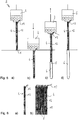
- FIGS. 5 and 6 which will be described together below, show an inventive method and apparatus for producing a shielding arrangement for shielding vibrations in the ground in a third embodiment.
- the present embodiment largely corresponds to those according to FIGS Figures 3 and 4, respectively, so that the similarities are referred to the above description.
- the same or corresponding components are provided with the same reference numerals, as in the FIGS. 3 and 4 ,
- the peculiarity of the procedure according to FIG. 5 consists in the manner of introduction and the design of the shielding means 6.
- the shielding means 6 is in the embodiment according to the FIGS. 5 and 6 as designed in liquid form or as a foam in the soil einbringbares and curable injection agent.
- As the hardenable injection agent for example, polyurethane foams or resins can be used.
- the procedure is similar as in FIG. 3 shown. First, the Absencisme 4 is introduced into the ground, as in the FIGS. 5a ) and 5b). After complete insertion of the AbsenkMechs 4 while displacing the soil and reaching the desired depth, the Absenk emotions 4 is pulled again.
- liquid injection medium is injected through injection channels 12, which exits at a lower end of the Absenk analysess 4 and fills the cavity formed by the Absenksammlung 4 when introduced into the ground.
- the pulling while simultaneously applying the injection means is in FIG. 5c ).
- the ejection of the injection medium is carried out with a corresponding pressure, which can be adjusted, for example, taking into account the viscosity of the injection medium and the soil condition.
- the injection agent cures and forms, after complete hardening a shielding element 6 in the ground, as in FIG. 5d ).
- the lowering body 4 can again be introduced into the ground in order here to produce the next shielding element by injecting the injection means.
- the Absenk manipulate 4 has over its length a plurality of injection tubes or channels 12 which extend from an upper end of the Absenk analysess to a lower end. These injection channels 12 are connected at the top via corresponding connection means with a supply line 13, via which the injection medium can be pressed.
- the injection channels 12 are guided in the embodiment shown on an outer side of the AbsenkMechs 4 along. However, it is also conceivable that the injection channels 12 are guided along within the AbsenkMechs 4, for example on the inner wall. This embodiment has the advantage that the channels are better protected against damage when introducing the AbsenkMechs 4 in the ground.
- FIGS. 7a) to 7e which will be described together below, a device according to the invention is shown in a further embodiment.
- the present embodiment largely corresponds to that of FIG. 2 , so that reference is made to the above description in terms of similarities.
- the same or corresponding components are provided with the same reference numerals, as in the above figures. Below, the features of the present embodiment will be discussed in detail.
- the Absenk Sciences 4 has a relatively large ratio of length L to width B, so that hereby relatively long shielding can be generated by a single insertion process in the ground.
- the rectangular basic shape of the Absenk analysess is recognizable, wherein the ratio of length to width of the Absenk analysess is greater than 10: 1 and about 14: 1.
- the Absenk Sciences 4 has a stiffener 15, which connects the two opposite side walls 16, 17 with each other and thus leads to increased rigidity of the AbsenkMechs 4.
- the stiffener 15 is designed in the form of a beam element which extends over the height of the AbsenkMechs and is connected to the side walls 16, 17, for example by means of welding. By the stiffener 15 two chambers 27, 28 are formed in the Absenkanalysis, in each of which a shielding element 6 is to be inserted.
- the device 2 according to FIG. 7 also has a traverse 21, which is placed on the Absenksammlung 4 and used for power transmission or distribution of the delivery device, not shown here on the Absenk Sciences 4.
- the traverse 21, which can also be referred to as a force distribution element, has a shape adapted to the Absenk Sciences 4.
- the traverse 21 has a centering section 22, with which the traverse 21 is inserted into an upper opening of the AbsenkMechs 4 and aligned with respect to this.
- an active section 23 connects, which serves for introducing forces into the Absenkoasa 4.
- the active portion 23 has a pressure surface 24 which cooperates in the inserted state on a support surface 25 of the Absenk emotionss.
- two brackets 26 are attached to which the applicator can be attached by means of clamps.
- the centering section 22 is bisected due to the stiffening 15 of the AbsenkMechs 4.
- the applicator not shown here is placed on the crosshead for introducing the AbsenkMechs in the ground and initiates a force or vibrations in this. By means of the traverse 21, the introduced forces or vibrations over the entire length of the AbsenkMechs 4 are introduced into this.
- To increase the stability in the force introduction section of the Absenk manipulate can be provided with a reinforcement.
- a displacement tip 9 is inserted, which is designed as a so-called lost tip.
- the displacement tip 9 is designed as a beam element having at its ends a plurality of upwardly facing positioning elements 14.
- the beam element 9 is placed on the opening of the Absenk analysess, wherein the positioning elements 14 have a Ausrichte- or guide function relative to the inner wall of the AbsenkMechs 4, and thus cause an alignment of the beam member 9 relative to the Absenk endeavor 4.
- the beam element 9 projects laterally beyond the side walls 16, 17 and end walls 18, 19 so that the frictional forces on the wall of the lowering body are reduced when introduced into the ground.
- the present device according to FIG. 7 Can be used both for shielding, as in the Figures 1 and 2 are shown, that is, which are already used before being introduced into the ground in the AbsenkConsequently, as well as for shielding, as in the FIGS. 3 and 4 are shown, that is, those that are used only after the introduction of the Absenk analysess in the ground.
- FIGS. 8a) to 8e which will be described together below, a device according to the invention is shown in a further embodiment.
- the present embodiment corresponds largely to those according to the FIGS. 7a) to 7e) , so that reference is made to the above description in terms of similarities.
- the same or corresponding components are provided with the same reference numerals, as in the above figures. Below, the features of the present embodiment will be discussed in detail.
- FIG. 8 a folding mechanism is provided instead of the lost tip.
- two flaps 29 are attached to the lower end of the AbsenkMechs 4, which are up and to pivot, so that they can close or release the opening.
- the operation of the flaps 29 is similar in so far as the lost tip, as the release the flaps 29 when pulling the AbsenkMechs the opening down.
- the present embodiment has two flaps 29; However, it is understood that embodiments with only one or even more than two flaps are conceivable.
Description
Die Erfindung betrifft ein Verfahren zum Herstellen einer Abschirmanordnung im Boden zum Abschirmen von Erschütterungen sowie eine entsprechende Vorrichtung zum Herstellen einer solchen Abschirmanordnung im Boden.The invention relates to a method for producing a shielding arrangement in the ground for shielding vibrations and to a corresponding device for producing such a shielding arrangement in the ground.
Von Schienen- und Straßenfahrzeugen, die überirdisch oder auch unterirdisch geführt sind, gehen Erschütterungen bzw. Schwingungen aus, die sich durch den Boden ausbreiten. Um derartige Schwingungen und den hiervon ausgehenden Einfluss auf im Schwingungsbereich befindliche Bauwerke abzumindern, sind bereits verschiedene Maßnahmen vorgeschlagen worden.From rail and road vehicles, which are guided above ground or underground, there are vibrations or vibrations that propagate through the ground. In order to mitigate such vibrations and the resulting influence on structures located in the vibration area, various measures have already been proposed.
Aus der
Aus der
Aus der
Aus
Aus der
Im Artikel "
Aus der
Aus der
Aus der
Insbesondere bei nicht oder nur wenig standfesten Böden, wie z. B. Sanden oder Kiesen, ist die Herstellung und Offenhaltung eines Bodenschlitzes mit erheblichem Aufwand verbunden. Hierfür ist beispielsweise eine seitliche Stützung mit einer temporären Verbauwand oder mit Stützflüssigkeit erforderlich. Beim Einsatz von Stützflüssigkeit besteht das Risiko des Versagens des offenen Schlitzes, was zu Bodenverformungen führen und Schäden an nahegelegenen Gleis- oder Verkehrsanlagen verursachen kann. Die Herstellung einer temporären Verbauwand hingegen ist sehr geräte- und arbeitsintensiv und somit verhältnismäßig aufwendig.Especially with no or only little stable soil, such. As sands or gravels, the production and keeping open a bottom slot is associated with considerable effort. For this purpose, for example, a lateral support with a temporary Verbauwand or with support fluid is required. The use of support fluid carries the risk of failure of the open slot, which can lead to ground deformations and damage to nearby track or traffic facilities. The production of a temporary Verbauwand, however, is very equipment and labor intensive and thus relatively expensive.
Hiervon ausgehend liegt der vorliegenden Erfindung die Aufgabe zugrunde, ein Verfahren zur Herstellung von Abschirmanordnungen im Boden vorzuschlagen, das sich einfach, sicher und schnell durchführen lässt. Eine weitergehende Aufgabe besteht darin, eine Vorrichtung zum Einbringen von Abschirmmittel in Boden vorzuschlagen, die eine einfache, sichere und schnelle Installation, insbesondere ohne aufwendige Herstellung und Offenhaltung eines Schlitzes, ermöglicht.On this basis, the present invention seeks to propose a method for producing Abschirmanordnungen in the ground, which can be carried out easily, safely and quickly. A further object is to propose a device for introducing shielding in soil, which allows a simple, safe and fast installation, in particular without costly production and keeping open a slot.
Die Lösung besteht in einem Verfahren nach Anspruch 1.The solution consists in a method according to claim 1.
Der Vorteil besteht darin, dass der Absenkkörper durch Verdrängung in den Boden eingebracht werden kann. Es ist demnach kein separates bzw. vorheriges Herstellen eines Bodenschlitzes erforderlich, so dass das vorgeschlagene Verfahren zeit- und kosteneffizient ist. Das Abschirmmittel kann vor oder nach dem Absenken des Absenkkörpers in diesen eingebracht werden. Beim erneuten Ziehen des Absenkkörpers tritt das Abschirmmittel nach unten aus diesem heraus, und zwar in den verdrängten Hohlraum, den der Absenkkörper beim Einbringen in den Boden geschaffen hat. Während des ganzen Vorgangs bilden die Seitenwände des Absenkkörpers eine sichere Abstützung für umliegendes Erdreich, so dass sich dieses Verfahren insbesondere für lockere Böden gut eignet. Der Absenkkörper bildet zumindest eine innere Kammer, in welcher das Abschirmmittel aufgenommen bzw. durch diese hindurchgeführt werden kann. Ein weiterer Vorteil besteht darin, dass bei der Durchführung des erfindungsgemäßen Verfahrens, aufgrund der Verdrängung des Absenckörpers, kein zu entsorgendes Bohrgut, wie Boden, beziehungsweise kein zu entsorgendes Rücklaufmaterial, wie Spülmittel, anfällt. Dies führt zu einem geringeren technischen Aufwand bei der Herstellung einer Abschirmanordnung im Boden und damit verringerten Kosten.The advantage is that the Absenkkörper can be introduced by displacement in the ground. Accordingly, no separate or prior production of a bottom slot is required, so that the proposed method is time and cost efficient. The shielding can be introduced before or after lowering the Absenkkörpers in this. When re-pulling the Absenkkörpers the shielding down out of this, in the displaced cavity, which has created the Absenkkörper when introduced into the ground. Throughout the process, the side walls of the Absenkkörpers form a secure support for surrounding soil, so that this method is particularly well suited for loose soils. The Absenkkörper forms at least one inner chamber, in which the shielding can be received or passed therethrough. Another advantage is that in the implementation of the method according to the invention, due to the displacement of the Absonckörpers, no cuttings to be disposed of, such as soil, or no to be disposed return material, such as detergent, obtained. This leads to less technical effort in the production of a shielding in the ground and thus reduced costs.
Das Abschirmmittel kann mehrere Ausgestaltungen haben. Nach einer ersten Möglichkeit kann das Abschirmmittel ein oder mehrere vorgefertigte(s) Abschirmelement(e) aufweisen. Diese Abschirmelemente sind insbesondere als starre Elemente gestaltet, die vor dem Einsetzen in den Rahmen vorgefertigt werden. Dabei ist die Form des Absenkkörpers an die Form des Abschirmelements angepasst. Vorzugsweise umfassen die Abschirmelemente ein Trägermaterial, das beispielsweise eine oder mehrere Stahlmatten aufweisen kann, sowie ein Dämmmaterial, das beispielsweise in Form von Dämmplatten, wie Styroporplatten, gestaltet sein kann, die mit dem Trägermaterial fest verbunden sind. Es versteht sich, dass die vorgefertigten Abschirmelemente auch als selbsttragende Elemente gestaltet sein können, beispielsweise aus Kunststoff, welche sowohl Trage- als auch Dämmfunktion beinhalten. Als vorgefertigte Abschirmelemente sind auch Gasmatten mit schützender Geotextilummantelung geeignet.The shielding means may have several configurations. According to a first possibility, the shielding means may comprise one or more prefabricated shielding element (s). These shielding elements are designed in particular as rigid elements, which are prefabricated before insertion into the frame. The shape of the Absenkkörpers adapted to the shape of the shielding. Preferably, the shielding elements comprise a carrier material which, for example, a or a plurality of steel mats, as well as an insulating material, which may be designed, for example in the form of insulation boards, such as polystyrene panels, which are firmly connected to the carrier material. It is understood that the prefabricated shielding elements can also be designed as self-supporting elements, for example made of plastic, which include both carrying and insulating function. As pre-fabricated shielding also gas mats with protective geotextile jacket are suitable.
Nach einer weiteren Möglichkeit kann das Abschirmmittel ein aushärtbares Injektionsmaterial sein, das während des Ziehens des Absenkkörpers in den dabei gebildeten Erdschlitz injiziert wird. In diesem Fall weist der Absenkkörper vorzugsweise mehrere Injektionsrohre auf, durch die das flüssige oder schaumförmige Abschirmmittel beim Ziehen des Absenkkörpers injiziert werden kann. Als erhärtbares Injektionsmaterial können beispielsweise Kunststoffschäume, wie Polyurethanschäume, oder Harze verwendet werden. Es ist ferner die Verwendung von schüttfähigem Material als Abschirmmittel denkbar, beispielsweise ein Granulat, das Kunststoff und/ oder ein anderes schwingungsdämpfendes schüttfähiges Material umfassen kann.According to another possibility, the shielding means may be a hardenable injection material which is injected during the pulling of the Absenkkörpers in the Erdschlitz formed thereby. In this case, the Absenkkörper preferably has a plurality of injection tubes through which the liquid or foam-like shielding agent can be injected when pulling the Absenkkörpers. As the hardenable injection material, for example, plastic foams such as polyurethane foams or resins can be used. It is also conceivable to use pourable material as a shielding agent, for example a granulate which may comprise plastic and / or another vibration-damping pourable material.
Der Absenkkörper kann bei dieser Ausführungsform mit injizierbarem oder schüttbarem Abschirmmittel in Form einer Bohle gestaltet sein. Die Düsöffnungen der Injektionsrohre befinden sich vorzugsweise an der Unterkante des Absenkkörpers bzw. der Bohle.The Absenkkörper can be designed in this embodiment with injectable or pourable shielding in the form of a screed. The nozzle openings of the injection tubes are preferably located on the lower edge of the Absenkkörpers or the screed.
Hinsichtlich der Verfahrensführung sind ebenfalls mehrere Möglichkeiten denkbar. Nach einer ersten Verfahrensführung kann das Abschirmelement gemeinsam mit dem Absenkkörper, in darin eingesetztem Zustand, in den Boden eingebracht werden. Nach einer alternativen zweiten Verfahrensführung wird das bzw. die Abschirmelemente erst in den Absenkkörper eingesetzt, nachdem letzterer in den Boden eingebracht worden ist.With regard to the process management, several possibilities are also conceivable. After a first procedure, the shielding element can be introduced together with the Absenkkörper, in it inserted state, in the ground. According to an alternative second procedure, the or the shielding is used only in the Absenkkörper after the latter has been introduced into the ground.
Die erste Verfahrensführung eignet sich besonders für robuste Abschirmelemente, wie mit Styroporplatten versehene Baustahlmatten. Dabei kann nach einer ersten Ausgestaltung am unteren Ende des Abschirmelements eine Verdrängungsspitze angebracht werden, welche den Boden beim Einbringen verdrängt. Die Verbindung der Verdrängungsspitze mit dem Abschirmelement kann beispielsweise mittels versenkten Bolzen oder Schweißen erfolgen. Der Absenkkörper wird auf das mit Verdrängungsspitze versehene Abschirmelement aufgesetzt, wobei insbesondere vorgesehen ist, dass die Verdrängungsspitze einen Krafteinleitungsabschnitt aufweist, der seitlich über das Abschirmelement vorsteht und an dem sich der Absenkkörper in aufgesetztem Zustand vertikal abstützen kann. So ist gewährleistet, dass auf den Absenkkörper einwirkende Kräfte über die zwischen Absenkkörper und Abstützabschnitt gebildete Flächenpaarung in die Verdrängungsspitze übertragen werden können.The first procedure is particularly suitable for robust shielding elements, such as styrofoam slabs. It can after a first Design at the lower end of the shielding a displacement tip are attached, which displaces the soil during insertion. The connection of the displacement tip with the shielding can be done for example by means of sunk bolts or welding. The Absenkkörper is placed on the provided with displacement tip shield, which is provided in particular that the displacement tip has a force introduction portion which protrudes laterally beyond the shielding and on which the Absenkkörper can support vertically in the attached state. This ensures that forces acting on the lowering body can be transmitted into the displacement tip via the surface pairing formed between the lowering body and the supporting section.
Alternativ zur Befestigung an dem Abschirmelement kann die Verdrängungsspitze nach einer zweiten Ausgestaltung auch an einem unteren Ende des Absenkkörpers angebracht werden. Dabei stützt sich die Verdrängungsspitze an dem Absenkkörper ab, so dass in den Absenkkörper eingeleitete Kräfte auf die Verdrängungsspitze übertragen werden. Diese Ausführungsform eignet sich sowohl für die erste, als auch für die zweite oben genannte Verfahrensführung. Nach beiden Ausgestaltungen mit Verdrängungsspitze verbleibt diese nach dem Ziehen des Absenkkörpers gemeinsam mit dem Abschirmelement im Boden. Dabei kann die Verdrängungsspitze nach einer günstigen Weiterbildung so ausgelegt werden, dass sie als Auftriebssicherung für gegebenenfalls anstehendes Grundwasser dient. Auf diese Weise wird verhindert, dass das darüberliegende Abschirmelement durch steigendes Grundwasser aufschwimmen kann.Alternatively to the attachment to the shielding element, according to a second embodiment, the displacement tip can also be attached to a lower end of the lowering body. In this case, the displacement tip is supported on the Absenkkörper, so that introduced into the Absenkkörper forces are transmitted to the displacement tip. This embodiment is suitable both for the first, as well as for the second method mentioned above. After both embodiments with displacement tip this remains after pulling the Absenkkörpers together with the shielding in the ground. In this case, the displacement tip can be designed for a favorable development so that it serves as a buoyancy protection for possibly pending groundwater. In this way it is prevented that the overlying shielding element can float due to rising groundwater.
Nach einer alternativen Ausgestaltung kann der Absenkkörper, anstelle einer verlorenen Verdrängungsspitze, an seinem unteren Ende einen Klappenmechanismus aufweisen. Hierfür können ein oder mehrere Klappen vorgesehen sein, welche die Öffnung des Absenkkörpers freigeben oder verschließen können. Die zumindest eine Klappe ist zunächst geschlossen, wenn der Absenkkörper mittels des Einbringgeräts unter Verdrängung in den Boden eingebracht wird, bis die gewünschte Tiefe erreicht ist. Das zumindest eine Abschirmelement kann dabei nach der ersten oder zweiten Verfahrensführung vor oder nach dem Absenken des Rahmenkörpers in diesen eingesetzt werden. Anschließend wird der Rahmenkörper wieder nach oben gezogen, wobei sich die Klappe an dem unteren Ende aufgrund des Eigengewichts öffnet. Beim weiteren Ziehen des Rahmenkörpers tritt das Abschirmelement aus diesem nach unten heraus und verbleibt im Boden.According to an alternative embodiment, the Absenkkörper, instead of a lost displacement tip, have at its lower end a flap mechanism. For this purpose, one or more flaps may be provided which can release or close the opening of the Absenkkörpers. The at least one flap is initially closed when the Absenkkörper is introduced by means of the loading device under displacement in the ground until the desired depth is reached. The at least one shielding element can after the first or second Procedure be used before or after lowering the frame body in this. Subsequently, the frame body is pulled up again, the flap opens at the lower end due to its own weight. Upon further pulling of the frame body, the shielding member emerges downwardly therefrom and remains in the ground.
Unabhängig davon, ob die Abschirmmittel vor oder nach dem Absenken des Absenkkörpers in diesen eingesetzt werden, wird die lichte Breite des Absenkkörpers so gewählt, dass zwischen der Innenwand und dem Abschirmelement genügend Spiel vorhanden ist, um den Absenkkörper nach Einbringen ziehen zu können, ohne das Abschirmelement mitzuziehen oder zu beschädigen. Dabei werden die lichte Breite und die Materialdicke des Absenkkörpers so gewählt, dass durch den beim Ziehen entstehenden verbleibenden Ringspalt im Boden lediglich geringe horizontale Bodenspannungen und daraus resultierende Bodenbewegungen auftreten.Regardless of whether the shielding are used before or after lowering the Absenkkörpers in this, the clear width of the Absenkkörpers is chosen so that between the inner wall and the shield enough clearance is available to pull the Absenkkörper after insertion can without Entrain or damage shielding. In this case, the clear width and the material thickness of the Absenkkörpers be chosen so that only slight horizontal ground tensions and resulting ground movements occur by the resulting during pulling remaining annular gap in the ground.
Die Lösung der obengenannten Aufgabe besteht weiter in einer Vorrichtung nach Anspruch 8.The solution of the above object is further in a device according to
Die Vorrichtung eignet sich insbesondere zur Durchführung des erfindungsgemäßen Verfahrens. Hiermit ergeben sich die obengenannten Vorteile, auf die hiermit Bezug genommen wird. Insbesondere ist hervorzuheben, dass der Rahmenkörper durch Verdrängung in den Boden eingebracht wird. Es ist demnach kein separates bzw. vorheriges Herstellen eines Bodenschlitzes erforderlich, was Zeit und Kosten spart.The device is particularly suitable for carrying out the method according to the invention. This results in the abovementioned advantages, to which reference is hereby made. In particular, it should be emphasized that the frame body is introduced by displacement in the ground. It is therefore no separate or prior making a bottom slot required, which saves time and money.
Gleichzeitig bilden die Seitenwände des Rahmenkörpers eine Abstützung für das umliegende Erdreich. Es fällt weder Aushub durch Graben eines Bodenschlitzes noch Rücklaufmaterial durch Spülen von Erdreich an. Das Abschirmmittel kann vor oder nach dem Einbringen des Rahmenkörpers in den Boden, auf einfache Weise in den Hohlraum des Rahmenkörpers eingebracht werden. Das Abschirmmittel tritt beim erneuten Ziehen des Rahmenkörpers aus dem Boden aus der zumindest einen Öffnung am unteren Ende aus dem Rahmenkörper heraus.At the same time, the side walls of the frame body form a support for the surrounding soil. There is no excavation by digging a bottom slit or return material by flushing soil. The shielding means can be introduced into the cavity of the frame body in a simple manner before or after the introduction of the frame body into the ground. The shielding means emerges from the frame body when the frame body is pulled out of the bottom from the at least one opening at the lower end.
Der Absenkkörper ist wiederverwendbar, das heißt nach dem Einbringen eines ersten Abschirmmittels in den Boden und Ziehen des Absenkkörpers, wird dieser benachbart zum ersten Abschirmmittel wieder in den Boden eingebracht, so dass hier - an das erste Abschirmmittel angrenzend - ein weiteres Abschirmmittel in den Boden eingebracht werden kann. Gemeinsam bilden die in den Boden eingebrachten Abschirmmittel dann eine Anordnung aus Abschirmmitteln, die auch als Abschirmwandung bezeichnet werden kann. Zwischen zwei benachbarten Abschirmmitteln kann ein Spalt gebildet sein; eine feste Verbindung ist nicht zwingend notwendig.The Absenkkörper is reusable, that is, after the introduction of a first shielding in the ground and pulling the Absenkkörpers, this is introduced adjacent to the first shielding again in the ground, so here - adjacent to the first shielding - introduced another shielding in the ground can be. Together, the shielding means introduced into the ground then form an arrangement of shielding means, which can also be referred to as Abschirmwandung. Between two adjacent shielding means, a gap may be formed; a permanent connection is not mandatory.
Das Abschirmmittel kann mehrere Ausgestaltungen haben. Nach einer ersten Möglichkeit umfasst das Abschirmmittel zumindest ein vorgefertigtes Abschirmelement, das in den Absenkkörper einsetzbar ist. Nach einer zweiten Möglichkeit kann das Abschirmmittel ein aushärtbares Injektionsmaterial sein, wobei der Absenkkörper zumindest einen Injektionskanal aufweist, durch den das aushärtbare Injektionsmaterial beim Ziehen des Absenkkörpers aus dem Boden injizierbar ist.The shielding means may have several configurations. According to a first possibility, the shielding means comprises at least one prefabricated shielding element which can be inserted into the lowering body. According to a second possibility, the shielding means may be a hardenable injection material, wherein the lowering body has at least one injection channel, through which the curable injection material can be injected from the floor when the body is pulled.
Bei Verwendung vorgefertigter Abschirmelemente sind generell zwei Verfahrensführungen denkbar. Und zwar kann das zumindest eine Abschirmelement vor dem Einbringen des Absenkkörpers in den Boden, oder erst danach in den Absenkkörper eingesetzt werden. Erstere Vorgehensweise ist besonders bei Einsatz von robusten Abschirmelementen geeignet, die derart gestaltet sind, dass sie beim Einbringen des Rahmens in den Boden aufgrund der eingeleiteten Kräfte keinen Schaden nehmen. Als Beispiel für einen solches Abschirmelement sei hier eine vorgefertigte Anordnung aus einer oder mehrerer mit Styroporplatten versehene Baustahlmatten genannt. Hier kann nach einer bevorzugten Weiterbildung vorgesehen sein, dass das zumindest eine Abschirmelement an einem unteren Ende eine Verdrängungsspitze mit einer Druckfläche aufweist, die mit einer entsprechenden Gegenfläche des Absenckörpers zusammenwirkt, so dass in den Absenkkörper eingeleitete Kräfte auf die Verdrängungsspitze übertragen werden.When using prefabricated shielding two process guides are generally conceivable. Namely, the at least one shielding element can be inserted into the bottom prior to the insertion of the lowering body or only then into the lowering body. The first approach is particularly suitable when using robust shielding, which are designed so that they take no damage when introducing the frame into the ground due to the forces introduced. As an example of such a shielding here is a prefabricated arrangement of one or more styrofoam plates provided with reinforcing steel mats called. Here, according to a preferred embodiment, it can be provided that the at least one shielding element has at a lower end a displacement tip with a pressure surface which cooperates with a corresponding counter surface of the Absenckörpers, so that forces introduced into the Absenkkörper be transferred to the displacement tip.
Bei Verwendung empfindlicherer Abschirmelemente sollten diese vorzugsweise nach dem Einbringen des Rahmens in den Boden eingesetzt werden. Ein Beispiel hierfür ist eine Anordnung aus Gasmatten mit schützender Geotextilummantelung als Abschirmelement. Unabhängig von der Ausgestaltung des Abschirmelements ist in jedem Fall vorgesehen, dass dieses derart gestaltet ist, dass es beim Ziehen des Absenkkörpers aus dessen Öffnung nach unten heraustreten kann, so dass es den Bodenschlitz ausfüllt.When using more sensitive shielding these should preferably be used after the introduction of the frame in the ground. An example of this is an arrangement of gas mats with protective Geotextilummantelung as shielding. Regardless of the configuration of the shielding is provided in any case that this is designed such that it can emerge when pulling the Absenkkörpers from the opening downwards so that it fills the bottom slot.
Vorzugsweise hat der Absenkkörper, im Querschnitt betrachtet, eine zumindest etwa rechteckige Grundform. Erfindungsgemäß hat der Absenkkörper, im Querschnitt betrachtet, eine längliche Grundform. Für ein effektives Herstellen langer Erschütterungsabschirmungen, beispielsweise entlang von Verkehrswegen, ist es besonders günstig, dass eine Länge des Absenkkörpers um ein Vielfaches größer ist, als eine Breite des Absenkkörpers; insbesondere kann vorgesehen sein, dass das Verhältnis von Länge zu Breite des Abschirmmittels bzw. Abschirmelements größer als 5:1, oder sogar größer als 10:1 ist.Preferably, the Absenkkörper, viewed in cross section, an at least approximately rectangular basic shape. According to the invention, the Absenkkörper, viewed in cross section, an elongated basic shape. For an effective production of long vibration shields, for example along traffic routes, it is particularly favorable that a length of the Absenkkörpers is greater by a multiple than a width of the Absenkkörpers; In particular, it can be provided that the ratio of length to width of the shielding or shielding element is greater than 5: 1, or even greater than 10: 1.
Zwischen zwei benachbarten in den Boden eingebrachten Abschirmmitteln kann ein Abstand vorgesehen sein. Es ist auch denkbar, dass die Abschirmmittel in Draufsicht betrachtet jeweils versetzt zum jeweils benachbarten Abschirmmittel angeordnet sind. Zwischen zwei einander gegenüberliegenden langen Seitenwänden des Absenkkörpers können ein oder mehrere Aussteifungselemente vorgesehen sein. Die Aussteifungselemente können parallel zu den kurzen Seitenwänden über die Höhe des Absenkkörpers verlaufen, so dass sie zwei Kammern des Absenkkörpers voneinander trennen. In diesem Fall können zwei Abschirmelemente in den Absenkkörper eingesetzt werden. Die langen und die kurzen Seitenwände des Absenkkörpers bilden in Draufsicht gemeinsam einen geschlossenen Rahmen; insofern kann der Absenkkörper auch als Rahmenkörper oder Hohlkörper bezeichnet werden.A distance may be provided between two adjacent shielding means introduced into the ground. It is also conceivable that viewed in plan view the shielding means are each arranged offset to the respective adjacent shielding means. Between two opposite long side walls of the Absenkkörpers one or more stiffening elements may be provided. The stiffening elements may extend parallel to the short side walls over the height of the Absenkkörpers so that they separate two chambers of the Absenkkörpers from each other. In this case, two shielding can be used in the Absenkkörper. The long and the short side walls of the Absenkkörpers form in plan view together a closed frame; In this respect, the Absenkkörper can also be referred to as a frame body or hollow body.
Die Installation der Abschirmmittel bzw. Abschirmelemente erfolgt mit einem oder mehreren Einbringgeräten. Als Einbringgerät eignen sich vorzugsweise Aufsatzrüttler, wobei auch andere Geräte, wie Fallhämmer oder Spundbohlenpressen, welche im Tiefbau zum Einbringen und Ziehen von Spundwandelementen oder Fertigteilpfählen zum Einsatz kommen, verwendet werden können. Das obere Ende des Absenkkörpers ist so ausgebildet, dass das Einbringgerät angebracht werden kann, beispielsweise durch Mittel zur Fixierung von hydraulischen Spannzangen bei Verwendung eines Aufsatzrüttlers oder Aufsetzen einer Rammhaube bei Verwendung eines Fallhammers. Die Verbindung zwischen dem Einbringgerät und dem Absenckörper erfolgt kraftschlüssig, um ein späteres Ziehen des Absenkkörpers zu ermöglichen. Um zu gewährleisten, dass der Absenkkörper in vertikaler Ausrichtung in den Boden eingebracht wird, wird das Einbringgerät vorzugsweise mäklergeführt. Alternativ kann der Absenkkörper durch eine versetz- oder verfahrbare Gerüstkonstruktion geführt werdenThe installation of the shielding or shielding is done with one or more applicators. Aufsatzgerät are preferably Aufsatzrüttler, with other devices, such as hammers or sheet pile presses, which are used in civil engineering for the introduction and removal of sheet pile elements or precast piles, can be used. The upper end of the Absenkkörpers is designed so that the introduction device can be attached, for example, by means for fixing hydraulic collets when using a Aufsatzrüttlers or putting on a Rammhaube when using a drop hammer. The connection between the applicator and the Absenckörper takes place frictionally to allow a later pulling the Absenkkörpers. In order to ensure that the Absenkkörper is introduced into the ground in a vertical orientation, the introduction device is preferably Macclergeführt. Alternatively, the Absenkkörper be guided by a displaceable or movable scaffolding structure
Die von dem Einbringgerät erzeugten Kräfte bzw. Vibrationen werden über die Traverse in den Absenkkörper eingeleitet. Dabei hat die Traverse vorzugsweise eine an den Absenkkörper angepasste Form. Insbesondere kann vorgesehen sein, dass die Traverse einen Zentrierabschnitt zum Zentrieren gegenüber dem Absenkkörper aufweist, sowie einen Wirkabschnitt zum Einbringen von Kräften in den Absenkkörper. Der Absenkkörper hat entsprechend an seinem oberen Ende eine Aufnahme für die Traverse und einen Krafteinleitungsabschnitt, über den Kräfte vom Wirkabschnitt der Traverse eingeleitet werden. Für eine Erhöhung der Stabilität im Krafteinleitungsabschnitt kann eine Armierung des Absenkkörpers vorgesehen werden. Die Traverse erfüllt mehrere Funktionen. Erstens bildet sie einen Adapter zwischen dem Einbringgerät und dem Absenkkörper; zweitens verteilt die Traverse die eingeleiteten Kräfte gleichmäßig über die gesamte Einleitungsfläche des Absenkkörpers. Auf diese Weise wird ein gleichmäßiges Einbringen des Absenkkörpers in den Boden ermöglicht, bzw. ein ungewünschtes Verkippen verhindert. Der Einwirkabschnitt der Traverse hat eine vorzugsweise umlaufende Druckfläche, welche zumindest mit dem größten Teil, vorzugsweise mit der gesamten Stirnseite des Absenkkörpers in Kontakt tritt. Auf diese Weise ist eine besonders gleichmäßige Krafteinleitung von der Traverse in den Absenkkörper gewährleistet.The forces or vibrations generated by the applicator are introduced via the traverse in the Absenkkörper. In this case, the traverse preferably has a shape adapted to the Absenkkörper. In particular, it can be provided that the traverse has a centering for centering against the Absenkkörper, and an active section for introducing forces into the Absenkkörper. The Absenkkörper has accordingly at its upper end a receptacle for the traverse and a force introduction section, are introduced via the forces of the active section of the traverse. For an increase in the stability in the force introduction section, a reinforcement of the Absenkkörpers can be provided. The crossbar fulfills several functions. First, it forms an adapter between the delivery device and the Absenkkörper; secondly, the traverse distributes the introduced forces uniformly over the entire introduction surface of the lower body. In this way, a uniform introduction of the Absenkkörpers is made possible in the ground, or prevents unwanted tilting. The Einwirkabschnitt the traverse has a preferably circumferential pressure surface, which comes into contact at least with the largest part, preferably with the entire end face of the Absenkkörpers. In this way, a particularly uniform force is ensured by the traverse in the Absenkkörper.
Nach einer bevorzugten Ausgestaltung ist der Absenkkörper durchgängig offen, das heißt mit Durchgangsöffnung zwischen dem oberen und unteren Ende gestaltet; insofern kann der Absenkkörper auch als Mantelrohr bezeichnet werden. Beim Einbringen des Absenkkörpers in den Boden ist das untere Ende des Absenkkörpers vorzugsweise geschlossen.According to a preferred embodiment, the Absenkkörper is continuously open, that is designed with through-opening between the upper and lower end; In this respect, the Absenkkörper can also be referred to as a jacket tube. When introducing the Absenkkörpers in the ground is the lower end of the Absenkkörpers preferably closed.
Hierfür kann nach einer ersten Möglichkeit vorgesehen sein, dass der Absenkkörper an seinem unteren Ende eine oder mehrere öffenbare Klappen aufweisen, wobei das Abschirmmittel bzw. Abschirmelement nach dem Öffnen der zumindest einen Klappe und beim Ziehen des Absenkkörpers aus diesem nach unten hindurchtreten kann. Dabei füllt das Abschirmmittel den durch den Absenkkörper verdrängten Raum aus und bildet so eine Abschirmwand bzw. einen Abschirmwandabschnitt im Boden. Nach einer zweiten Möglichkeit hat der Absenkkörper an seinem unteren Ende eine Verdrängungsspitze, die nch dem erneuten Ziehen des Absenkkörpers im Boden verbleibt.For this purpose, it can be provided according to a first possibility that the Absenkkörper have at its lower end one or more openable flaps, wherein the shielding or shielding element can pass after opening the at least one flap and pulling the Absenkkörpers from this down. In this case, the shielding means fills the displaced by the Absenkkörper space and thus forms a shielding wall or a Abschirmwandabschnitt in the ground. After a second possibility, the Absenkkörper has at its lower end a displacement tip, which remains nch the renewed pulling the Absenkkörpers in the ground.
Das bevorzugte Material für den Absenkkörper und die Verdrängungsspitze bzw. die Klappe ist Stahl, welcher bei ausreichender Dimensionierung für die Einbauspannungen eine geringer Wandungsdicke ermöglicht und eine hohe Formstabilität aufweist. Der Kopfbereich des Absenkkörpers kann verstärkt ausgeführt werden, um auch bei wiederholtem Einsatz den dabei eingeleiteten Installationsspannungen standzuhalten.The preferred material for the Absenkkörper and the displacement tip or the flap is steel, which allows for sufficient dimensions for the installation voltages a small wall thickness and has a high dimensional stability. The head region of the Absenkkörpers can be made reinforced, to withstand the case initiated installation voltages even with repeated use.
Bevorzugte Ausführungsformen werden nachstehend anhand der Zeichnungsfiguren erläutert. Hierin zeigt
- Figur 1
- ein erfindungsgemäßes Verfahren zum Herstellen einer Abschirmanordnung zum Abschirmen von Erschütterungen im Boden in einer ersten Ausführungsform mit den Verfahrensschritten:
- a) Einsetzen eines Abschirmmittels in einen Absenkkörper,
- b) Einbringen des Absenkkörpers in den Boden unter Verdrängung des Bodens bis zum Erreichen einer gewünschten Tiefe,
- c) Ziehen des Absenkkörpers, wobei das Abschirmmittel im Boden verbleibt,
- d) bis der Absenkkörper vollständig aus dem Boden gezogen ist;
Figur 2- das Abschirmelement gemäß
Figur 1a ) schematisch- a) in einer Vorderansicht;
- b) in einer Seitenansicht;
Figur 3- ein erfindungsgemäßes Verfahren zum Herstellen einer Abschirmanordnung zum Abschirmen von Erschütterungen im Boden in einer zweiten Ausführungsform mit den Verfahrensschritten:
- a), b) Einbringen eines Absenkkörpers in den Boden unter Verdrängung des Bodens bis zum Erreichen einer gewünschten Tiefe,
- c) Einsetzen eines Abschirmmittels in den Absenkkörper,
- d) Ziehen des Absenkkörpers aus dem Boden,
- e) wobei das Abschirmmittel im Boden verbleibt;
Figur 4- das Abschirmelement gemäß
Figur 3a ) schematisch- a) in einer Vorderansicht;
- b) in einer Seitenansicht;
Figur 5- ein erfindungsgemäßes Verfahren zum Herstellen einer Abschirmanordnung zum Abschirmen von Erschütterungen im Boden in einer dritten Ausführungsform mit den Verfahrensschritten:
- a), b) Einbringen eines Absenkkörpers in den Boden unter Verdrängung des Bodens bis zum Erreichen einer gewünschten Tiefe,
- c) Ziehen des Absenkkörpers unter gleichzeitigem Injizieren von Abschirmmittel durch den Absenkkörper,
- d) bis der Absenkkörper vollständig aus dem Boden gezogen ist;
Figur 6- den Absenkkörper gemäß
Figur 5a ) schematisch- a) in einer Vorderansicht;
- b) in einer Seitenansicht;
Figur 7- ein Abschirmelement zur Durchführung des Verfahrens gemäß
Figur 1 oder 3 in einer weiteren Ausführungsform- a) in Seitenansicht,
- b) in Draufsicht auf die Traverse,
- c) im Schnitt gemäß Schnittlinie A-A aus
Figur 7a , - d) in Vorderansicht,
- e) im Schnitt gemäß Schnittlinie B-B aus
Figur 7a ;
Figur 8- ein Abschirmelement zur Durchführung des Verfahrens gemäß
Figur 1 oder 3 in einer weiteren Ausführungsform- a) in Seitenansicht,
- b) in Draufsicht auf die Traverse,
- c) im Schnitt gemäß Schnittlinie A-A aus
Figur 8a , - d) in Vorderansicht,
- e) im Schnitt gemäß Schnittlinie B-B aus
Figur 8a ;
- FIG. 1
- an inventive method for producing a shielding arrangement for shielding vibrations in the ground in a first embodiment with the method steps:
- a) inserting a shielding means into a lowering body,
- b) introducing the Absenkkörpers in the ground while displacing the soil until reaching a desired depth,
- c) pulling the Absenkkörpers, wherein the shielding agent remains in the ground,
- d) until the Absenkkörper is completely pulled out of the ground;
- FIG. 2
- the shielding according to
FIG. 1a ) schematically- a) in a front view;
- b) in a side view;
- FIG. 3
- an inventive method for producing a shielding arrangement for shielding vibrations in the ground in a second embodiment with the method steps:
- a), b) introducing a Absenkkörpers in the soil while displacing the soil until reaching a desired depth,
- c) inserting a shielding means in the Absenkkörper,
- d) pulling the Absenkkörpers from the ground,
- e) wherein the shielding agent remains in the ground;
- FIG. 4
- the shielding according to
FIG. 3a ) schematically- a) in a front view;
- b) in a side view;
- FIG. 5
- an inventive method for producing a shielding arrangement for shielding vibrations in the ground in a third embodiment with the method steps:
- a), b) introducing a Absenkkörpers in the soil while displacing the soil until reaching a desired depth,
- c) pulling the lower body while simultaneously injecting shielding means through the Absenkkörper,
- d) until the Absenkkörper is completely pulled out of the ground;
- FIG. 6
- the Absenkkörper according to
FIG. 5a ) schematically- a) in a front view;
- b) in a side view;
- FIG. 7
- a shielding element for performing the method according to
FIG. 1 or3 in a further embodiment- a) in side view,
- b) in plan view of the traverse,
- c) in section according to section line AA
Figure 7a . - d) in front view,
- e) in section along section line BB
Figure 7a ;
- FIG. 8
- a shielding element for performing the method according to
FIG. 1 or3 in a further embodiment- a) in side view,
- b) in plan view of the traverse,
- c) in section according to section line AA
FIG. 8a . - d) in front view,
- e) in section along section line BB
FIG. 8a ;
Die
Eine erfindungsgemäße Vorrichtung 2 zur Durchführung des Verfahrens umfasst ein Einbringgerät 3 sowie einen länglichen Absenkkörper 4, der mittels des Einbringgeräts in den Boden 11 einbringbar ist. Das Einbringgerät 3 ist in Form eines Aufsatzrüttlers gestaltet, der auf den Absenkkörper 4 aufgesetzt wird. Der Aufsatzrüttler erzeugt Schwingungen, die in den Absenkkörper 4 eingeleitet werden. Gleichzeitig werden Kräfte nach vertikal unten ausgeübt, welche den Absenkkörper nach unten in den Boden bewegen. Die von dem Einbringgerät 3 erzeugten Kräfte bzw. Vibrationen werden über eine hier nicht dargestellte Traverse in den Absenkkörper 4 eingeleitet. Es versteht sich, dass anstelle des her gezeigten Aufsatzrüttlers auch andere Einbringgeräte verwendet werden können, beispielsweise Fallhämmer oder Spundbohlenpressen.A
Der Absenkkörper 4 hat, im Querschnitt betrachtet, eine etwa rechteckige Grundform, wobei das Verhältnis von Länge zu Breite des Absenkkörpers insbesondere größer als 5:1, und vorzugsweise sogar größer als 10:1 ist. Durch diese Ausgestaltung lassen sich lange Erschütterungsabschirmungen, beispielsweise entlang von Verkehrswegen, besonders günstig und effektiv herstellen. Der Absenkkörper 4 ist durchgehend offen gestaltet, das heißt zwischen dem oberen und dem unteren Ende des Rohrkörpers ist eine Durchgangsöffnung 5 gebildet. Die Durchgangsöffnung 5 ermöglicht, dass der Absenkkörper 4 auf ein Abschirmmittel 6 aufgesetzt werden kann, beziehungsweise das Abschirmmittel 6, nach dem Einbringen in den Boden, nach unten aus der Öffnung des Absenkkörpers 4 austreten kann.The
Das Abschirmmittel 6 ist bei der vorliegenden Ausführungsform als vorgefertigtes Abschirmelement gestaltet, welches insbesondere in den
Im Folgenden wird das erfindungsgemäße Verfahren in einer ersten Ausführungsform anhand der
Die
Im Folgenden wird insbesondere auf die Unterschiede eingegangen. Die Besonderheit der Verfahrensführung gemäß
Eine weitere Besonderheit der vorliegenden Ausführungsform ist in der Ausgestaltung des Abschirmelements 6 zu sehen. Dieses umfasst eine Mehrzahl von etwa horizontal verlaufender Zylinderkörpern, die in Form von Gasmatten mit schützender Textilummantelung gestaltet sein können.
Die Verfahrensführungen nach
Die
Im Folgenden wird insbesondere auf die Unterschiede eingegangen. Die Besonderheit der Verfahrensführung gemäß
Es ist insbesondere in
In den
Der Absenkkörper 4 hat ein relativ großes Verhältnis von Länge L zu Breite B, so dass sich hiermit relativ lange Abschirmabschnitte durch einen einzigen Einbringvorgang im Boden erzeugen lassen. Insbesondere in
Die Vorrichtung 2 gemäß
Am unteren Ende 20 des Absenkkörpers 4 ist eine Verdrängungsspitze 9 eingesetzt, die als sogenannte verlorene Spitze gestaltet ist. Die Verdrängungsspitze 9 ist als Balkenelement gestaltet, das an seinen Enden mehrere nach oben weisende Positionierelemente 14 aufweist. Das Balkenelement 9 wird auf die Öffnung des Absenkkörpers aufgesetzt, wobei die Positionierelemente 14 eine Ausrichte- bzw. Führungsfunktion gegenüber der Innenwand des Absenkkörpers 4 haben, und damit eine Ausrichtung des Balkenelements 9 relativ zum Absenkkörper 4 bewirken. Das Balkenelement 9 steht über die Seitenwände 16, 17 und Stirnwände 18, 19 seitlich vor, so dass die Reibkräfte an der Wandung des Absenkkörpers beim Einbringen in den Boden verringert sind. Beim Ziehen des Absenkkörpers 4 verbleibt das Balkenelement 9 aufgrund seines Eigengewichts und der darauf abgestützten Abschirmelemente im Boden. Damit wird die Öffnung freigegeben und die beiden Abschirmelemente 6 können nach unten aus der Öffnung des Absenkkörpers 4 austreten.At the
Die vorliegende Vorrichtung gemäß
In den
Im Unterschied zur Ausführungsform gemäß
- 22
- Vorrichtungdevice
- 33
- EinbringgerätEinbringgerät
- 44
- AbsenkkörperAbsenkkörper
- 55
- Öffnungopening
- 66
- Abschirmmittelscreening
- 77
- Trägermaterialsupport material
- 88th
- Dämmmaterialinsulation
- 99
- Verdrängungsspitzepeak displacement
- 1010
- KrafteinleitungsabschnitteForce transmission sections
- 1111
- Bodenground
- 1212
- Injektionskanalinjection channel
- 1313
- Versorgungsleitungsupply line
- 1414
- Positionierelementpositioning
- 1515
- Aussteifungstiffening
- 1616
- SeitenwandSide wall
- 1717
- SeitenwandSide wall
- 1818
- Stirnwandbulkhead
- 1919
- Stirnwandbulkhead
- 2121
- Traversetraverse
- 2222
- Zentrierabschnittcentering
- 2323
- Wirkabschnitteffective section
- 2424
- Druckflächeprint area
- 2525
- Stützflächesupport surface
- 2626
- Halterungholder
- 2727
- Kammerchamber
- 2828
- Kammerchamber
- 2929
- Klappeflap
- BB
- Breitewidth
- LL
- Längelength
Claims (14)
- Method of producing a shielding assembly for shielding against vibrations in the ground with the method steps:inserting a sinking body (4) into the ground by means of an insertion device (3) until a desired depth is reached, wherein the sinking body (4) seen in cross-section has a length (L) multiple times greater than a width (B), wherein the insertion device (3) is detachably connected to a crossbeam (21) for introducing forces into the sinking body (4) and the crossbeam (21) is detachably mounted on the sinking body (4) wherein the sinking body (4) displaces and supports the ground during insertion,introducing shielding means (6) into the sinking body (4) wherein at its lower end the sinking body has at least one opening (5) through which the shielding means (6) can exit downwards,pulling the sinking body (4) out of the ground, wherein the shielding means (6) remains in the ground and at least partially fills a hollow space created by the sinking body (4).
- Method according to claim 1,
characterised in that
a hardenable or pourable injection material is used as the shielding means (6). - Method according to claim 1,
characterised in that
a prefabricated shielding element is used as the shielding means (6), which, in particular, comprises a support material (7) and an insulating material (8). - Method according to claim 3,
characterised in that
at the lower end of the shielding element (6) a displacement tip (9) is applied,
that the shielding element (6) is inserted into and driven into the ground together with the sinking body (4),
wherein the displacement tip (9) connected to the shielding element (6) is supported on the lower end of the sinking body (4) so that driving-in forces introduced into the sinking body (4) are transmitted to the displacement tip (9). - Method according to any one of claims 1 to 3,
characterised in that
a displacement tip (9) is applied to the lower end of the sinking body (4), wherein the displacement tip (9) is supported on the sinking body (4) so that forces introduced into the sinking body (4) are transmitted to the displacement tip (9), wherein the sinking body (4) with the displacement tip (9) is inserted into the ground. - Method according to any one of claims 3 to 5, characterised in that,
after pulling out the sinking body (4), the displacement tip (9) remains in the ground together with the shielding element (6), wherein the displacement tip is, in particular, designed so that it acts as buoyancy protection for any present groundwater. - Method according to any one of claims 1 to 3,
characterised in that
the sinking body (4) comprises at least one openable flap (29) which can open or close the opening (5),
wherein the at least one flap (29) is closed when the sinking body (4) is inserted into the ground and
wherein the at least one flap (29) is opened when the desired depth is reached that the shielding means (6) can exit downwards out of the sinking body (4). - Device for introducing shielding means into the ground to protect against vibrations, comprising:a sinking body (4) which can be introduced into the ground and pulled out from the ground and which on its lower end has an opening (5) through which a shielding means (6) introduceable into the sinking body (4) can exit downwards when it is pulled out,characterised by a crossbeam (21) for introducing forces into the sinking body (4) wherein the crossbeam (21) can be detachably mounted on the sinking body (4), andan insertion device (3) for introducing forces into the crossbeam (21), wherein the insertion device can be detachably connected to the crossbeam for force introduction,wherein the sinking body (4), seen in cross-section, is designed in such a way that a length (L) of the sinking body (4) is multiple times larger than a width (B) of the sinking body (4).
- Device according to claim 8,
characterised in that
at its lower end the sinking body (4) has at least one flap (29) which can be opened so that the shielding element (6) can pass out downwards through the opening (5) of the sinking body (4). - Device according to any one of claims 8 or 9,
characterised in that
at its upper end the sinking body (4) forms a receptacle for the crossbeam (21) and has a support surface (25) via which the forces are transmittable from the crossbeam (21) into the sinking body (4). - Device according to any one of claims 8 to 10,
characterised in that
the crossbeam (21) has a centring section (22) for centring with regard to the sinking body (4) as well as an operating section (23) for introducing forces into the sinking body (4). - Device according to any one of claims 8 to 11,
characterised in that
the shielding means (6) comprises at least one shielding element (6) which is insertable into the sinking body (4), wherein the shielding element (6) is designed in such a way that on pulling out the sinking body (4) it can exit downward through its opening (5). - Device according to any one of claims 8 to 12,
characterised in that
at a lower end the at least one shielding element (6) or the sinking body (4) has a displacement tip (9) with an operating surface, wherein the operating surface is designed in such a way that forces introduced into the sinking body (4) are transmitted to the displacement tip (9). - Device according to any one of claims 8 to 11,
characterised in that
the shielding means (6) is a hardenable injection material, wherein the sinking body (4) comprises at least one injection channel (12) through which the hardenable injection material can be injected on pulling out the sinking body (4).
Priority Applications (2)
| Application Number | Priority Date | Filing Date | Title |
|---|---|---|---|
| ES12160865T ES2748008T3 (en) | 2012-03-22 | 2012-03-22 | Procedure for producing a protective arrangement for protection against vibrations on the ground, as well as device for it |
| EP12160865.7A EP2642031B1 (en) | 2012-03-22 | 2012-03-22 | Method of producing a protection assembly for protecting against tremors in the ground and device for same |
Applications Claiming Priority (1)
| Application Number | Priority Date | Filing Date | Title |
|---|---|---|---|
| EP12160865.7A EP2642031B1 (en) | 2012-03-22 | 2012-03-22 | Method of producing a protection assembly for protecting against tremors in the ground and device for same |
Publications (2)
| Publication Number | Publication Date |
|---|---|
| EP2642031A1 EP2642031A1 (en) | 2013-09-25 |
| EP2642031B1 true EP2642031B1 (en) | 2019-07-10 |
Family
ID=45936885
Family Applications (1)
| Application Number | Title | Priority Date | Filing Date |
|---|---|---|---|
| EP12160865.7A Active EP2642031B1 (en) | 2012-03-22 | 2012-03-22 | Method of producing a protection assembly for protecting against tremors in the ground and device for same |
Country Status (2)
| Country | Link |
|---|---|
| EP (1) | EP2642031B1 (en) |
| ES (1) | ES2748008T3 (en) |
Citations (4)
| Publication number | Priority date | Publication date | Assignee | Title |
|---|---|---|---|---|
| JPS6344006A (en) * | 1986-08-08 | 1988-02-25 | Sumitomo Metal Ind Ltd | Earthquake-proof reinforcing construction for previously constructed harbour structure |
| CN2432251Y (en) * | 2000-07-20 | 2001-05-30 | 蔡崇晓 | High-effective through-layer top pile-pressing machine |
| JP3660634B2 (en) * | 2002-03-04 | 2005-06-15 | 株式会社ピーエス三菱 | PC well press-fitting method and apparatus |
| JP2009024365A (en) * | 2007-07-18 | 2009-02-05 | Shimizu Corp | Creation method for ground vibration propagation suppressing structure |
Family Cites Families (7)
| Publication number | Priority date | Publication date | Assignee | Title |
|---|---|---|---|---|
| JPS6023729B2 (en) * | 1978-06-08 | 1985-06-08 | 新日本製鐵株式会社 | Construction method for vibration-proof sheet pile walls |
| GB8418991D0 (en) * | 1984-07-25 | 1984-08-30 | Cementation Piling & Found | Ground treatment |
| SE457546B (en) * | 1985-05-14 | 1989-01-09 | Cappe Carl Theodor | Vibration insulating protective screen |
| BE1008237A6 (en) * | 1994-04-13 | 1996-02-20 | Interbuild | PROCESS FOR GROUNDING AN ANTI-VIBRATION SCREEN. |
| DE19504363C2 (en) | 1994-07-29 | 2002-04-25 | Helmut Kramer | Wall construction to protect buildings from vibrations and element for the production of the wall construction |
| JP4823939B2 (en) * | 2007-02-15 | 2011-11-24 | 株式会社不動テトラ | Ground vibration isolation method |
| DE102010001839A1 (en) * | 2010-02-09 | 2011-08-11 | Alexander Degen | Rüttlervorrichtung with a lifting unit and method for the production of material columns |
-
2012
- 2012-03-22 EP EP12160865.7A patent/EP2642031B1/en active Active
- 2012-03-22 ES ES12160865T patent/ES2748008T3/en active Active
Patent Citations (4)
| Publication number | Priority date | Publication date | Assignee | Title |
|---|---|---|---|---|
| JPS6344006A (en) * | 1986-08-08 | 1988-02-25 | Sumitomo Metal Ind Ltd | Earthquake-proof reinforcing construction for previously constructed harbour structure |
| CN2432251Y (en) * | 2000-07-20 | 2001-05-30 | 蔡崇晓 | High-effective through-layer top pile-pressing machine |
| JP3660634B2 (en) * | 2002-03-04 | 2005-06-15 | 株式会社ピーエス三菱 | PC well press-fitting method and apparatus |
| JP2009024365A (en) * | 2007-07-18 | 2009-02-05 | Shimizu Corp | Creation method for ground vibration propagation suppressing structure |
Also Published As
| Publication number | Publication date |
|---|---|
| EP2642031A1 (en) | 2013-09-25 |
| ES2748008T3 (en) | 2020-03-12 |
Similar Documents
| Publication | Publication Date | Title |
|---|---|---|
| EP2010717B1 (en) | Method for lining ditches | |
| EP3298201B1 (en) | System for supporting a ditch | |
| EP0244851B1 (en) | Tubular pile for a combined sheet-piling wall | |
| EP0509385B1 (en) | Method for creating concrete bodies and cement bodies in the ground | |
| EP0788572B1 (en) | Building underpinning process | |
| EP2642031B1 (en) | Method of producing a protection assembly for protecting against tremors in the ground and device for same | |
| EP2003251B1 (en) | Holder stem | |
| DE2824562A1 (en) | ARTICULATED DEVICE FOR STRENGTHENING THE WALLS OF BUILDING DITCHES, PIPE DITCHES, etc. | |
| WO2019158459A1 (en) | Shoring equipment | |
| DE3516044A1 (en) | Method for screening against underground vibrations, a device for carrying out the method as well as a damping wall for use in the method | |
| DE102016107899B4 (en) | Method of making a sheet pile wall and support tube | |
| EP0672794B1 (en) | Deep stratum compacting device | |
| EP2722443B1 (en) | Method and device for shoring deep trenches | |
| DE4319239C2 (en) | Method and device for the foundation of load-bearing structural parts or foundation parts | |
| DE19803074C2 (en) | Press shaft and method for creating one | |
| DE3926787C2 (en) | Method and device for inserting and anchoring a tensile pile | |
| DE4312231C2 (en) | Method and device for manufacturing flat components in the floor | |
| DE4035646A1 (en) | Driving support into ground - involves H=section member with drill auger in each recess | |
| DE102004013017B4 (en) | Device for manufacture of in-situ concrete foundations for overhead line masts, for example, comprises prefabricated shuttering component with outer walls or at least one outer wall having circular openings | |
| DE102007017633B3 (en) | Closed shaft i.e. mine shaft, securing method, involves diagonally boring set of holes in vertical projection, and attaching and loading carrier, core rods and cement suspension or concrete into holes | |
| DE102017118777B4 (en) | Shoring for trenches or trench-like structures | |
| DE3941641C1 (en) | Drive unit for foundation I beams - has ground drills within beams, retrieved after beams are properly installed | |
| DE4419694C2 (en) | Device for exchanging soil material | |
| DE102012022164A1 (en) | Structural system for diverting vertical and horizontal loads from elongated building areas to less stable ground, has soil columns, which are covered with geotextile material and form multiple linked systems by connecting elements | |
| DE2161392C2 (en) | Method and device for creating tunnels in an open excavation |
Legal Events
| Date | Code | Title | Description |
|---|---|---|---|
| PUAI | Public reference made under article 153(3) epc to a published international application that has entered the european phase |
Free format text: ORIGINAL CODE: 0009012 |
|
| AK | Designated contracting states |
Kind code of ref document: A1 Designated state(s): AL AT BE BG CH CY CZ DE DK EE ES FI FR GB GR HR HU IE IS IT LI LT LU LV MC MK MT NL NO PL PT RO RS SE SI SK SM TR |
|
| AX | Request for extension of the european patent |
Extension state: BA ME |
|
| 17P | Request for examination filed |
Effective date: 20140325 |
|
| RBV | Designated contracting states (corrected) |
Designated state(s): AL AT BE BG CH CY CZ DE DK EE ES FI FR GB GR HR HU IE IS IT LI LT LU LV MC MK MT NL NO PL PT RO RS SE SI SK SM TR |
|
| STAA | Information on the status of an ep patent application or granted ep patent |
Free format text: STATUS: EXAMINATION IS IN PROGRESS |
|
| 17Q | First examination report despatched |
Effective date: 20161103 |
|
| GRAP | Despatch of communication of intention to grant a patent |
Free format text: ORIGINAL CODE: EPIDOSNIGR1 |
|
| STAA | Information on the status of an ep patent application or granted ep patent |
Free format text: STATUS: GRANT OF PATENT IS INTENDED |
|
| INTG | Intention to grant announced |
Effective date: 20180912 |
|
| GRAJ | Information related to disapproval of communication of intention to grant by the applicant or resumption of examination proceedings by the epo deleted |
Free format text: ORIGINAL CODE: EPIDOSDIGR1 |
|
| STAA | Information on the status of an ep patent application or granted ep patent |
Free format text: STATUS: EXAMINATION IS IN PROGRESS |
|
| GRAP | Despatch of communication of intention to grant a patent |
Free format text: ORIGINAL CODE: EPIDOSNIGR1 |
|
| STAA | Information on the status of an ep patent application or granted ep patent |
Free format text: STATUS: GRANT OF PATENT IS INTENDED |
|
| INTC | Intention to grant announced (deleted) | ||
| INTG | Intention to grant announced |
Effective date: 20190128 |
|
| GRAS | Grant fee paid |
Free format text: ORIGINAL CODE: EPIDOSNIGR3 |
|
| GRAA | (expected) grant |
Free format text: ORIGINAL CODE: 0009210 |
|
| STAA | Information on the status of an ep patent application or granted ep patent |
Free format text: STATUS: THE PATENT HAS BEEN GRANTED |
|
| AK | Designated contracting states |
Kind code of ref document: B1 Designated state(s): AL AT BE BG CH CY CZ DE DK EE ES FI FR GB GR HR HU IE IS IT LI LT LU LV MC MK MT NL NO PL PT RO RS SE SI SK SM TR |
|
| REG | Reference to a national code |
Ref country code: GB Ref legal event code: FG4D Free format text: NOT ENGLISH |
|
| REG | Reference to a national code |
Ref country code: CH Ref legal event code: EP Ref country code: AT Ref legal event code: REF Ref document number: 1153704 Country of ref document: AT Kind code of ref document: T Effective date: 20190715 |
|
| RAP2 | Party data changed (patent owner data changed or rights of a patent transferred) |
Owner name: KELLER HOLDING GMBH |
|
| REG | Reference to a national code |
Ref country code: DE Ref legal event code: R096 Ref document number: 502012015010 Country of ref document: DE |
|
| REG | Reference to a national code |
Ref country code: IE Ref legal event code: FG4D Free format text: LANGUAGE OF EP DOCUMENT: GERMAN |
|
| REG | Reference to a national code |
Ref country code: CH Ref legal event code: NV Representative=s name: DENNEMEYER AG, CH |
|
| REG | Reference to a national code |
Ref country code: NL Ref legal event code: MP Effective date: 20190710 |
|
| REG | Reference to a national code |
Ref country code: LT Ref legal event code: MG4D |
|
| PG25 | Lapsed in a contracting state [announced via postgrant information from national office to epo] |
Ref country code: HR Free format text: LAPSE BECAUSE OF FAILURE TO SUBMIT A TRANSLATION OF THE DESCRIPTION OR TO PAY THE FEE WITHIN THE PRESCRIBED TIME-LIMIT Effective date: 20190710 Ref country code: BG Free format text: LAPSE BECAUSE OF FAILURE TO SUBMIT A TRANSLATION OF THE DESCRIPTION OR TO PAY THE FEE WITHIN THE PRESCRIBED TIME-LIMIT Effective date: 20191010 Ref country code: NL Free format text: LAPSE BECAUSE OF FAILURE TO SUBMIT A TRANSLATION OF THE DESCRIPTION OR TO PAY THE FEE WITHIN THE PRESCRIBED TIME-LIMIT Effective date: 20190710 Ref country code: PT Free format text: LAPSE BECAUSE OF FAILURE TO SUBMIT A TRANSLATION OF THE DESCRIPTION OR TO PAY THE FEE WITHIN THE PRESCRIBED TIME-LIMIT Effective date: 20191111 Ref country code: LT Free format text: LAPSE BECAUSE OF FAILURE TO SUBMIT A TRANSLATION OF THE DESCRIPTION OR TO PAY THE FEE WITHIN THE PRESCRIBED TIME-LIMIT Effective date: 20190710 Ref country code: NO Free format text: LAPSE BECAUSE OF FAILURE TO SUBMIT A TRANSLATION OF THE DESCRIPTION OR TO PAY THE FEE WITHIN THE PRESCRIBED TIME-LIMIT Effective date: 20191010 Ref country code: SE Free format text: LAPSE BECAUSE OF FAILURE TO SUBMIT A TRANSLATION OF THE DESCRIPTION OR TO PAY THE FEE WITHIN THE PRESCRIBED TIME-LIMIT Effective date: 20190710 Ref country code: FI Free format text: LAPSE BECAUSE OF FAILURE TO SUBMIT A TRANSLATION OF THE DESCRIPTION OR TO PAY THE FEE WITHIN THE PRESCRIBED TIME-LIMIT Effective date: 20190710 |
|
| PG25 | Lapsed in a contracting state [announced via postgrant information from national office to epo] |
Ref country code: IS Free format text: LAPSE BECAUSE OF FAILURE TO SUBMIT A TRANSLATION OF THE DESCRIPTION OR TO PAY THE FEE WITHIN THE PRESCRIBED TIME-LIMIT Effective date: 20191110 Ref country code: RS Free format text: LAPSE BECAUSE OF FAILURE TO SUBMIT A TRANSLATION OF THE DESCRIPTION OR TO PAY THE FEE WITHIN THE PRESCRIBED TIME-LIMIT Effective date: 20190710 Ref country code: GR Free format text: LAPSE BECAUSE OF FAILURE TO SUBMIT A TRANSLATION OF THE DESCRIPTION OR TO PAY THE FEE WITHIN THE PRESCRIBED TIME-LIMIT Effective date: 20191011 Ref country code: AL Free format text: LAPSE BECAUSE OF FAILURE TO SUBMIT A TRANSLATION OF THE DESCRIPTION OR TO PAY THE FEE WITHIN THE PRESCRIBED TIME-LIMIT Effective date: 20190710 Ref country code: LV Free format text: LAPSE BECAUSE OF FAILURE TO SUBMIT A TRANSLATION OF THE DESCRIPTION OR TO PAY THE FEE WITHIN THE PRESCRIBED TIME-LIMIT Effective date: 20190710 |
|
| REG | Reference to a national code |
Ref country code: ES Ref legal event code: FG2A Ref document number: 2748008 Country of ref document: ES Kind code of ref document: T3 Effective date: 20200312 |
|
| PG25 | Lapsed in a contracting state [announced via postgrant information from national office to epo] |
Ref country code: TR Free format text: LAPSE BECAUSE OF FAILURE TO SUBMIT A TRANSLATION OF THE DESCRIPTION OR TO PAY THE FEE WITHIN THE PRESCRIBED TIME-LIMIT Effective date: 20190710 |
|
| PG25 | Lapsed in a contracting state [announced via postgrant information from national office to epo] |
Ref country code: DK Free format text: LAPSE BECAUSE OF FAILURE TO SUBMIT A TRANSLATION OF THE DESCRIPTION OR TO PAY THE FEE WITHIN THE PRESCRIBED TIME-LIMIT Effective date: 20190710 Ref country code: EE Free format text: LAPSE BECAUSE OF FAILURE TO SUBMIT A TRANSLATION OF THE DESCRIPTION OR TO PAY THE FEE WITHIN THE PRESCRIBED TIME-LIMIT Effective date: 20190710 Ref country code: IT Free format text: LAPSE BECAUSE OF FAILURE TO SUBMIT A TRANSLATION OF THE DESCRIPTION OR TO PAY THE FEE WITHIN THE PRESCRIBED TIME-LIMIT Effective date: 20190710 Ref country code: RO Free format text: LAPSE BECAUSE OF FAILURE TO SUBMIT A TRANSLATION OF THE DESCRIPTION OR TO PAY THE FEE WITHIN THE PRESCRIBED TIME-LIMIT Effective date: 20190710 Ref country code: PL Free format text: LAPSE BECAUSE OF FAILURE TO SUBMIT A TRANSLATION OF THE DESCRIPTION OR TO PAY THE FEE WITHIN THE PRESCRIBED TIME-LIMIT Effective date: 20190710 |
|
| PG25 | Lapsed in a contracting state [announced via postgrant information from national office to epo] |
Ref country code: SM Free format text: LAPSE BECAUSE OF FAILURE TO SUBMIT A TRANSLATION OF THE DESCRIPTION OR TO PAY THE FEE WITHIN THE PRESCRIBED TIME-LIMIT Effective date: 20190710 Ref country code: IS Free format text: LAPSE BECAUSE OF FAILURE TO SUBMIT A TRANSLATION OF THE DESCRIPTION OR TO PAY THE FEE WITHIN THE PRESCRIBED TIME-LIMIT Effective date: 20200224 Ref country code: SK Free format text: LAPSE BECAUSE OF FAILURE TO SUBMIT A TRANSLATION OF THE DESCRIPTION OR TO PAY THE FEE WITHIN THE PRESCRIBED TIME-LIMIT Effective date: 20190710 Ref country code: CZ Free format text: LAPSE BECAUSE OF FAILURE TO SUBMIT A TRANSLATION OF THE DESCRIPTION OR TO PAY THE FEE WITHIN THE PRESCRIBED TIME-LIMIT Effective date: 20190710 |
|
| REG | Reference to a national code |
Ref country code: DE Ref legal event code: R097 Ref document number: 502012015010 Country of ref document: DE |
|
| PLBE | No opposition filed within time limit |
Free format text: ORIGINAL CODE: 0009261 |
|
| STAA | Information on the status of an ep patent application or granted ep patent |
Free format text: STATUS: NO OPPOSITION FILED WITHIN TIME LIMIT |
|
| PG2D | Information on lapse in contracting state deleted |
Ref country code: IS |
|
| 26N | No opposition filed |
Effective date: 20200603 |
|
| PG25 | Lapsed in a contracting state [announced via postgrant information from national office to epo] |
Ref country code: SI Free format text: LAPSE BECAUSE OF FAILURE TO SUBMIT A TRANSLATION OF THE DESCRIPTION OR TO PAY THE FEE WITHIN THE PRESCRIBED TIME-LIMIT Effective date: 20190710 |
|
| PG25 | Lapsed in a contracting state [announced via postgrant information from national office to epo] |
Ref country code: MC Free format text: LAPSE BECAUSE OF FAILURE TO SUBMIT A TRANSLATION OF THE DESCRIPTION OR TO PAY THE FEE WITHIN THE PRESCRIBED TIME-LIMIT Effective date: 20190710 |
|
| REG | Reference to a national code |
Ref country code: DE Ref legal event code: R084 Ref document number: 502012015010 Country of ref document: DE |
|
| REG | Reference to a national code |
Ref country code: BE Ref legal event code: MM Effective date: 20200331 |
|
| PG25 | Lapsed in a contracting state [announced via postgrant information from national office to epo] |
Ref country code: LU Free format text: LAPSE BECAUSE OF NON-PAYMENT OF DUE FEES Effective date: 20200322 |
|
| PG25 | Lapsed in a contracting state [announced via postgrant information from national office to epo] |
Ref country code: IE Free format text: LAPSE BECAUSE OF NON-PAYMENT OF DUE FEES Effective date: 20200322 |
|
| PG25 | Lapsed in a contracting state [announced via postgrant information from national office to epo] |
Ref country code: BE Free format text: LAPSE BECAUSE OF NON-PAYMENT OF DUE FEES Effective date: 20200331 |
|
| GBPC | Gb: european patent ceased through non-payment of renewal fee |
Effective date: 20200322 |
|
| PG25 | Lapsed in a contracting state [announced via postgrant information from national office to epo] |
Ref country code: GB Free format text: LAPSE BECAUSE OF NON-PAYMENT OF DUE FEES Effective date: 20200322 |
|
| PG25 | Lapsed in a contracting state [announced via postgrant information from national office to epo] |
Ref country code: MT Free format text: LAPSE BECAUSE OF FAILURE TO SUBMIT A TRANSLATION OF THE DESCRIPTION OR TO PAY THE FEE WITHIN THE PRESCRIBED TIME-LIMIT Effective date: 20190710 Ref country code: CY Free format text: LAPSE BECAUSE OF FAILURE TO SUBMIT A TRANSLATION OF THE DESCRIPTION OR TO PAY THE FEE WITHIN THE PRESCRIBED TIME-LIMIT Effective date: 20190710 |
|
| PG25 | Lapsed in a contracting state [announced via postgrant information from national office to epo] |
Ref country code: MK Free format text: LAPSE BECAUSE OF FAILURE TO SUBMIT A TRANSLATION OF THE DESCRIPTION OR TO PAY THE FEE WITHIN THE PRESCRIBED TIME-LIMIT Effective date: 20190710 |
|
| PGFP | Annual fee paid to national office [announced via postgrant information from national office to epo] |
Ref country code: FR Payment date: 20230316 Year of fee payment: 12 Ref country code: AT Payment date: 20230308 Year of fee payment: 12 |
|
| PGFP | Annual fee paid to national office [announced via postgrant information from national office to epo] |
Ref country code: ES Payment date: 20230406 Year of fee payment: 12 Ref country code: DE Payment date: 20230316 Year of fee payment: 12 Ref country code: CH Payment date: 20230401 Year of fee payment: 12 |