EP2641661B1 - Système d'application graphique - Google Patents
Système d'application graphique Download PDFInfo
- Publication number
- EP2641661B1 EP2641661B1 EP12160353.4A EP12160353A EP2641661B1 EP 2641661 B1 EP2641661 B1 EP 2641661B1 EP 12160353 A EP12160353 A EP 12160353A EP 2641661 B1 EP2641661 B1 EP 2641661B1
- Authority
- EP
- European Patent Office
- Prior art keywords
- spattering
- target surface
- nozzle
- spatial
- orientation
- Prior art date
- Legal status (The legal status is an assumption and is not a legal conclusion. Google has not performed a legal analysis and makes no representation as to the accuracy of the status listed.)
- Active
Links
Images


Classifications
-
- B—PERFORMING OPERATIONS; TRANSPORTING
- B05—SPRAYING OR ATOMISING IN GENERAL; APPLYING FLUENT MATERIALS TO SURFACES, IN GENERAL
- B05B—SPRAYING APPARATUS; ATOMISING APPARATUS; NOZZLES
- B05B12/00—Arrangements for controlling delivery; Arrangements for controlling the spray area
- B05B12/08—Arrangements for controlling delivery; Arrangements for controlling the spray area responsive to condition of liquid or other fluent material to be discharged, of ambient medium or of target ; responsive to condition of spray devices or of supply means, e.g. pipes, pumps or their drive means
- B05B12/12—Arrangements for controlling delivery; Arrangements for controlling the spray area responsive to condition of liquid or other fluent material to be discharged, of ambient medium or of target ; responsive to condition of spray devices or of supply means, e.g. pipes, pumps or their drive means responsive to conditions of ambient medium or target, e.g. humidity, temperature position or movement of the target relative to the spray apparatus
- B05B12/124—Arrangements for controlling delivery; Arrangements for controlling the spray area responsive to condition of liquid or other fluent material to be discharged, of ambient medium or of target ; responsive to condition of spray devices or of supply means, e.g. pipes, pumps or their drive means responsive to conditions of ambient medium or target, e.g. humidity, temperature position or movement of the target relative to the spray apparatus responsive to distance between spray apparatus and target
-
- B—PERFORMING OPERATIONS; TRANSPORTING
- B05—SPRAYING OR ATOMISING IN GENERAL; APPLYING FLUENT MATERIALS TO SURFACES, IN GENERAL
- B05B—SPRAYING APPARATUS; ATOMISING APPARATUS; NOZZLES
- B05B12/00—Arrangements for controlling delivery; Arrangements for controlling the spray area
-
- B—PERFORMING OPERATIONS; TRANSPORTING
- B05—SPRAYING OR ATOMISING IN GENERAL; APPLYING FLUENT MATERIALS TO SURFACES, IN GENERAL
- B05B—SPRAYING APPARATUS; ATOMISING APPARATUS; NOZZLES
- B05B12/00—Arrangements for controlling delivery; Arrangements for controlling the spray area
- B05B12/08—Arrangements for controlling delivery; Arrangements for controlling the spray area responsive to condition of liquid or other fluent material to be discharged, of ambient medium or of target ; responsive to condition of spray devices or of supply means, e.g. pipes, pumps or their drive means
- B05B12/12—Arrangements for controlling delivery; Arrangements for controlling the spray area responsive to condition of liquid or other fluent material to be discharged, of ambient medium or of target ; responsive to condition of spray devices or of supply means, e.g. pipes, pumps or their drive means responsive to conditions of ambient medium or target, e.g. humidity, temperature position or movement of the target relative to the spray apparatus
- B05B12/122—Arrangements for controlling delivery; Arrangements for controlling the spray area responsive to condition of liquid or other fluent material to be discharged, of ambient medium or of target ; responsive to condition of spray devices or of supply means, e.g. pipes, pumps or their drive means responsive to conditions of ambient medium or target, e.g. humidity, temperature position or movement of the target relative to the spray apparatus responsive to presence or shape of target
-
- B—PERFORMING OPERATIONS; TRANSPORTING
- B05—SPRAYING OR ATOMISING IN GENERAL; APPLYING FLUENT MATERIALS TO SURFACES, IN GENERAL
- B05B—SPRAYING APPARATUS; ATOMISING APPARATUS; NOZZLES
- B05B12/00—Arrangements for controlling delivery; Arrangements for controlling the spray area
- B05B12/14—Arrangements for controlling delivery; Arrangements for controlling the spray area for supplying a selected one of a plurality of liquids or other fluent materials or several in selected proportions to a spray apparatus, e.g. to a single spray outlet
- B05B12/1472—Arrangements for controlling delivery; Arrangements for controlling the spray area for supplying a selected one of a plurality of liquids or other fluent materials or several in selected proportions to a spray apparatus, e.g. to a single spray outlet separate supply lines supplying different materials to separate outlets of the spraying apparatus
-
- B—PERFORMING OPERATIONS; TRANSPORTING
- B05—SPRAYING OR ATOMISING IN GENERAL; APPLYING FLUENT MATERIALS TO SURFACES, IN GENERAL
- B05D—PROCESSES FOR APPLYING FLUENT MATERIALS TO SURFACES, IN GENERAL
- B05D1/00—Processes for applying liquids or other fluent materials
- B05D1/34—Applying different liquids or other fluent materials simultaneously
-
- B—PERFORMING OPERATIONS; TRANSPORTING
- B41—PRINTING; LINING MACHINES; TYPEWRITERS; STAMPS
- B41J—TYPEWRITERS; SELECTIVE PRINTING MECHANISMS, i.e. MECHANISMS PRINTING OTHERWISE THAN FROM A FORME; CORRECTION OF TYPOGRAPHICAL ERRORS
- B41J2/00—Typewriters or selective printing mechanisms characterised by the printing or marking process for which they are designed
- B41J2/005—Typewriters or selective printing mechanisms characterised by the printing or marking process for which they are designed characterised by bringing liquid or particles selectively into contact with a printing material
- B41J2/01—Ink jet
- B41J2/07—Ink jet characterised by jet control
-
- B—PERFORMING OPERATIONS; TRANSPORTING
- B41—PRINTING; LINING MACHINES; TYPEWRITERS; STAMPS
- B41J—TYPEWRITERS; SELECTIVE PRINTING MECHANISMS, i.e. MECHANISMS PRINTING OTHERWISE THAN FROM A FORME; CORRECTION OF TYPOGRAPHICAL ERRORS
- B41J3/00—Typewriters or selective printing or marking mechanisms characterised by the purpose for which they are constructed
- B41J3/407—Typewriters or selective printing or marking mechanisms characterised by the purpose for which they are constructed for marking on special material
- B41J3/4073—Printing on three-dimensional objects not being in sheet or web form, e.g. spherical or cubic objects
-
- G—PHYSICS
- G01—MEASURING; TESTING
- G01B—MEASURING LENGTH, THICKNESS OR SIMILAR LINEAR DIMENSIONS; MEASURING ANGLES; MEASURING AREAS; MEASURING IRREGULARITIES OF SURFACES OR CONTOURS
- G01B11/00—Measuring arrangements characterised by the use of optical techniques
- G01B11/002—Measuring arrangements characterised by the use of optical techniques for measuring two or more coordinates
-
- B—PERFORMING OPERATIONS; TRANSPORTING
- B41—PRINTING; LINING MACHINES; TYPEWRITERS; STAMPS
- B41J—TYPEWRITERS; SELECTIVE PRINTING MECHANISMS, i.e. MECHANISMS PRINTING OTHERWISE THAN FROM A FORME; CORRECTION OF TYPOGRAPHICAL ERRORS
- B41J29/00—Details of, or accessories for, typewriters or selective printing mechanisms not otherwise provided for
- B41J29/38—Drives, motors, controls or automatic cut-off devices for the entire printing mechanism
-
- G—PHYSICS
- G01—MEASURING; TESTING
- G01B—MEASURING LENGTH, THICKNESS OR SIMILAR LINEAR DIMENSIONS; MEASURING ANGLES; MEASURING AREAS; MEASURING IRREGULARITIES OF SURFACES OR CONTOURS
- G01B11/00—Measuring arrangements characterised by the use of optical techniques
- G01B11/02—Measuring arrangements characterised by the use of optical techniques for measuring length, width or thickness
- G01B11/03—Measuring arrangements characterised by the use of optical techniques for measuring length, width or thickness by measuring coordinates of points
-
- G—PHYSICS
- G01—MEASURING; TESTING
- G01C—MEASURING DISTANCES, LEVELS OR BEARINGS; SURVEYING; NAVIGATION; GYROSCOPIC INSTRUMENTS; PHOTOGRAMMETRY OR VIDEOGRAMMETRY
- G01C11/00—Photogrammetry or videogrammetry, e.g. stereogrammetry; Photographic surveying
- G01C11/04—Interpretation of pictures
- G01C11/06—Interpretation of pictures by comparison of two or more pictures of the same area
Definitions
- the present invention relates generally to a graphical application system according to claim 1, to a graphical application method according to claim 13 and to a computer program product.
- the desire to apply a layer of spattering material onto a target surface is spread over a lot of different technological areas.
- There are various reasons for apply spattering materials to surfaces with the most common being the desire to protect the surface against environmental influence or to fulfil aesthetic demands such as the desire to apply certain, often multi-coloured, graphical patterns onto the surface or on certain areas of the surface.
- the spattering as a process can include or be painting, coating, plating, inking, cladding, varnishing, spraying, sprinkling, texturing, overcoating, colouring, tinting or staining by expelling material to be applied to a target surface from a nozzle means.
- spatterings powder coatings and paint-sprayings by airbrushes or painting guns, but there are many other different types of spatterings like for example sprayed plaster as known from boat construction, sprayed mineral wool, sprayed or gunned concrete, sprayed asbestos, underbody coating as known from cars or other spatterwork.
- sandblasting is a very similar field of the art wherein, instead of covering a surface by spattering material, the surface is eroded by an expelled jet of erosive material with almost analogous principles as used in spattering.
- the document FR 2 850 322 discloses a device for printing an image on a large surface that may be held and moved manually and is able to determine position and direction on a surface.
- the device uses this knowledge of its current position to determine which colour needs to be applied on the surface. This determination is accomplished by matching the determined coordinates and an image stored in a memory of the device. The stored image may then be superimposed to the surface to be painted.
- a GPS controlled paint spray system comprises a paint sprayer driver program and a GPS paint sprayer.
- the GPS paint sprayer includes a GPS receiver, a geographical converter for enabling a user to convert a drawing pattern to geographical locations, a location comparator for detecting a location match between the geographical locations of the drawing pattern and a current GPS-based location, and a spray nozzle to spray paint at matched locations.
- Said geographical drawing pattern can be marked onto either a field, a wall, or a parking lot.
- US 2009/0022879 relates to a method for applying paints or varnishes to large surfaces by means of a displaceable, paint applying device which is controlled in a position-dependent manner.
- Said device comprises a displaceable part of a real time position measuring system using reference marks.
- KR 102006009588 provides a method for controlling an injection position of a painting articulated robot, to automatically operate arm-positions of an articulated robot by remote control so that a painting material exactly injects to an object.
- JP 10-264060 a system is provided to perform teaching of movements to a robot arm - by anyone, easily and in a short time - to perform painting by maintaining a painting machine at a right location and attitude, regardless of the skilfulness of a worker.
- the advancing route of the painting machine is calculated by an image processor, and the location and attitude of the painting machine are calculated by a distance/attitude calculator, based on the output signals of an image sensor and a distance sensor which are together mounted at the tip of a robot arm.
- control parameter of each axis of the robot arm is outputted to a driving device and the control parameter of each axis of the robot arm, which is moved by the driving device, is stored in a storage device in time sequence, while a feedback control is performed so as to maintain the distance of the painting machine and the painting surface to a prescribed value, to face the painting machine to the painting surface and to move the painting machine along the advancing route.
- JP 2006-320825 describes an automatic coating vehicle for painting, e.g. an aircraft, wherein the thickness of the paintwork has to be quite accurate - for once to achieve a sufficient protection of the surface on one hand and to keep the weight of the applied paint as low as possible on the other hand. It includes arm control means to control operation and movement of an arm with an actuator head, and to perform a painting process with respect to a surface to be coated based on the information of the coating area or region stored in a memory means and the attitude and position information of said arm. The position of the vehicle and the head are determined using a GPS, as well as a range finder for measuring a distance between the head and an object.
- the document DE 10 2008 015 258 relates to a painting robot for painting motor vehicle bodies by means of a atomizer (also known as nebulizer) for spattering the surface, that is guided by the painting robot. Applying multicolour paint is realized using a paint changer.
- a atomizer also known as nebulizer
- FR 2 785 230 refers to a ground logo imprinting technique for graphical reproduction of a drawing reproduced on the ground.
- the technique traces contours on the ground from a computer driven optical system. The contours traced out are then filled in with jet paint pulverization.
- the ground logo imprinting technique produces a ground print of a predefined advertising logo or drawing.
- a stencil, formed by a computer integrated optical system is projected onto the ground and jet paint pulverization is applied to the ground surface.
- KR 100812725 a method for controlling the position and angle of a painting robot is provided to execute painting works at the same spray distance and the progressive speed of a spray target point within an orthogonal painting zone by controlling a spray gun at the proper rotational angular speed, access speed, and separation speed.
- the goal is to generate a uniform spraying on the surface.
- US 5,935,657 discloses a multiple nozzle paint spraying system with two separate banks of spray nozzles. Both banks are supplied by paint from an airless pressurized source, and each individual bank has a shut-off valve to stop the flow of pressurized paint to that respective bank.
- the entire assembly is mounted on a roller stand which has a pair of arms extending laterally outward. During use, the painter merely activates the paint spray and pushes the apparatus along the wall. The lateral arms maintain the spray nozzles at a fixed distance from the wall, and a coat of paint can be applied to the wall uniformly and quickly.
- US 2008/0152807 , US 2011/0199431 , US 7,350,890 and US 7,922,272 are referring to methods and devices for applying an accurately positioned graphic image on a large contoured surface, such as the body of an aircraft.
- the apparatus used therein can comprise a rail positioning system to be mounted on a portion of the surface on which the graphic image is to be applied.
- the graphic image application system is controlled by software to operate a positioning system and a graphic image application system.
- the basic principle used in those surface spattering applications is to expel or eject a spattering material such as paint from a nozzle means onto a target surface.
- a spattering material such as paint
- there is pressure built up inside or before the nozzle which forces the spattering material out of the nozzle or the spattering material is carried away by a jet of gas or liquid which is ejected through or next to the nozzle.
- the most common examples for doing so are the ones known from painting guns or airbrushes and the ones known from ink-jet printing.
- New ink-jet printer like technology is available to paint with narrow spot sizes of less than one centimetre even from 10 cm distance.
- Such low divergence expelling techniques allow also spraying without masking, real-time colour mixing or colour changing over the area painted or colour fading from one colour to another.
- Non-flat (3D) surfaces are a further challenge as well as sudden interruptions of the target surface which need to be spattered, for example walls to be painted which comprise cables or pipes mounted on the surface which have to be avoided or an aeroplane-body comprising windows which should be excluded from painting.
- a spatial referencing of the application-unit with respect to the target surface has to be established.
- a spatial referencing of the spattering unit over the whole target range is required to achieve such.
- a further object of the present invention is to provide an improved surface spattering system which can spatter the target according to a desired spattering data by a spatial referencing of the spattering device with respect to the target surface.
- a further object is to provide a surface spattering system which aids the user in fulfilling the spattering tasks and to achieve the desired spattering results and characteristics, in particular over large target areas.
- a special object of the invention is to aid a user in accurately applying a predefined spattering pattern onto a target surface by a spattering device.
- a further object of the invention is to provide a system comprising a nozzle means which is capable of automatic adjusting its expelling characteristics dependent on its spatial reference and the characteristics of the target surface such as e.g. target-shape, present spattering colour, present spattering thickness, present spattered and non-spattered areas, temperature, etc.
- a particular object of the invention is to provide a system which avoids the need of pre mixing spattering materials to desired colour or material characteristics and also omit or reduce the thereby involved exchange and cleaning process effort.
- Another particular object of the invention is to automatically adjust the expelling characteristics of a spattering device, dependent on the present spattering task and the spatial location and movement of the device relative to the target which is determined by a spatial referencing unit that is simple to set up.
- a graphical application system with a movable surface spattering device comprising at least one nozzle means for an expelling of a spattering material onto a target surface is presented.
- the expelling can be continuous, resulting in an uninterrupted stream of spattering material, or pulsed by ejecting small separated portions or drops of material, whereby in case of high pulses-repetition frequency the pulsed-ejection can also be interpreted as a quasi-continuous stream of spattering material.
- the spattering device comprises a nozzle control mechanism to control characteristics of the expelling of the nozzle means, in particular expelling-direction, -speed, - divergence, -spreading, -shape and/or -material rate, pulse timing, pulse duration and pulse repetition.
- the spattering device comprises a spattering material supply which can be linked to an internal or external material tank.
- a storage comprises desired spattering data, which can be embodied as a fixed installed memory means, as a slot for receiving a memory card, USB-Stick or the like as well as wired or wireless network storage.
- the desired spattering data is predefined and comprised in a digital image or CAD-model memorized on the storage.
- a spatial referencing unit is located externally of the spattering device and references the spattering device relative to the target surface, in particular in at least five degrees of freedom by position and angle.
- a computation means to automatically control the expelling by the nozzle control mechanism according to information gained by the spatial referencing unit and according to the desired spattering data.
- the computation means is built in such a way that an actual or forecasted spattering spot, as the actual of forecasted spatterable area on the target surface, is evaluated and adjusted by changing the characteristics of expelling of the nozzle means in such a way that the target surface is spattered according to the desired spattering data.
- the spattering spot is thereby primarily dependent on the actual or forecasted spatial reference of the spattering device, the actual or forecasted set of characteristics of the expelling of the nozzle means and a actual measured, calculated or forecasted distance and inclination of the nozzle means relative to the target surface.
- the characteristics of expelling of the nozzle means is controlled according to a determined presently spatterable area on the target surface, which is dependent on the spatial reference of the spattering device, the direction of the expelling of the nozzle means and a measured distance from the nozzle means to the target surface, in a way to achieve a spattering of the target surface according to the desired spattering data.
- the computation means is built in such a way to control the nozzle means for a preferably unmasked application of the spattering material to the target surface according to the desired spattering data.
- expelling systems are "sucking" the spattering material out of the nozzle means by a bypassing jet of air or gas building up a negative pressure and carrying away the spattering material in direction of the target.
- the presently spatterable area can be defined as the portion of the target surface that would be hit by a then expelled spattering material in form of a drop, a stream of drops or a continuous stream of material from the nozzle means towards the target surface in the present direction of expelling and the present divergence of the stream as examples of characteristics of the expelling.
- the size of presently spatterable area on the target surface is dependent on this divergence and on the distance between the nozzle means looked at and the target surface.
- the shape of the presently spatterable area on the target surface can further be dependent on the inclination of the direction of expelling relative to the target surface.
- the spattering device could be a handheld painting gun which automatically adjusts the expelling characteristics of the nozzle(s) according to the distance and/or inclination to the target surface to achieve a desired coating of the target surface by the spattering material.
- the spattering device can also comprise an automatic positioning of the nozzle means relative to a body of the spattering device within a certain region, for example embodied in form of 2D plotter device allowing a Cartesian positioning of the nozzle within a frame of the device.
- the body of the spattering device or the nozzle itself has still to be referenced with respect to the target surface.
- the desired spattering data outreaches the positioning range of the nozzle within the spattering device.
- the spattering device requires a relocation with respect to the target surface to achieve an accurate stitching of the multiple parts of the desired spattering pattern which results from the relocation of the device. Therefore, a spatial referencing of the spattering device, in particular of its body, has to be established by the spatial referencing unit according to the present invention.
- the referencing of the nozzle to the target can be established in a step wise approach, for example by a first referencing the spattering device's body with respect to the target surface according to the invention, and a second referencing of the nozzle means to the device's body by a motorized positioning unit with position sensor.
- the nozzle means itself can be directly referenced according to the present invention, regardless whether the nozzle is positionable within the spattering device or the whole spattering with its nozzle(s) is movable.
- the spattering process can for example be further observed by an imaging unit at the spattering device, aligned in direction of the nozzle means, to verify the progress and to compare it with the desired result. For example, a monitoring of the full coverage of the desired area on the target surface can be accomplished and - if required - the expelling characteristic can be adjusted in such a way to achieve the desired spattering results.
- An example of a spattering task is the spraying of a paint pattern such as a logo of a company, advertising graphics or other textual or graphical items onto a target surface by manually running the painting device over a wall, ground, ceiling, sheet metal, vehicle part or another target object.
- a paint pattern such as a logo of a company, advertising graphics or other textual or graphical items onto a target surface by manually running the painting device over a wall, ground, ceiling, sheet metal, vehicle part or another target object.
- this can be done indoors as well as outdoors, in particular by a setup which allows easy handling and erecting, also at remote sites.
- rechargeable batteries and/or air tanks it is also possible to use the spattering device even in difficult to access or remote areas where a power supply is quit difficult to establish.
- the spattering device decides whether or not to expel or spray spattering material like paint, based on the spatial reference of the nozzle relative to the target. Therefore, the spatial referencing unit communicates data comprising position and orientation information to the computation device. In the decision whether to spray paint or not, the device incorporates information of the desired spattering data, like whether the present area should be painted, should remain unpainted or has already been painted.
- the spattering device or the associated computation means can comprise a data storage wherein a history of locations of already spattered areas is stored online while spattering.
- the storage also comprises the desired spattering data, which is stored as a spatially dependent desired pattern to be applied to the target.
- desired spattering data does not only mean information regarding a plain, smooth, uniform covering of a target surface with a single spattering material, as e.g. in classic paint gun spraying of single coloured car bodies, but a spattering more comparable to the art of airbrush painting for applying patterns like in colourizing model making, billboard painting, text or lettering applications to surfaces or the like.
- the desired pattern to be applied to the target can be based on a digital CAD like design of the pattern. If necessary, for example in case of curved target surfaces or surrounding or objects, which define where to start spattering, where to stop, etc. can also be comprised in the digital design or model, which can be represented in a two or three dimensional model.
- the control of the spattering process which is dependent on the expelling of the spattering material, which is done by a means herein referred to as nozzle, has certain characteristics like expelling direction, divergence, pressure, speed, material rate, etc. some of which can be fixed as well as variably controlled by a nozzle control mechanism. In a simple case, this is an on/off control, but there are many advanced methods known to influence the expelling, in particular in the technical area of airbrushes, painting guns or ink-jet printing.
- control of the spattering process can further be dependent on information regarding the presently used spattering material which information can comprise colour, type, viscosity, etc. This information can either be entered manually or determined automatically.
- the device can store the areas already painted in a real-time manner, and for example also visualize this by an overlay of the desired spattering data and the actual progress of spattering, for example on a display or projected directly onto the target.
- the spattering device can comprise a single or multiple nozzle means, e.g. aligned in rows or spraying bars.
- the nozzle control mechanism can adjust each single nozzle in a short reaction time.
- the nozzle characteristics can also be adjusted for multiple nozzles by a single actuator.
- the control-algorithm for the nozzles can comprise a prediction of the reaction time.
- the high dynamics and uncertainties of the guidance can be overcome or at least reduced by a correction of the expelling characteristics like painting pressure, jet width and direction in real-time.
- the expelling direction can be adjusted either by angular adjustments of the nozzles expelling direction, in particular by some mechanical micro drives or by adjusting the nozzle shape or injecting air from the sides.
- the shape of the ejected stream of material can be influenced by the nozzle control mechanism, for example by hydrodynamic means like injecting air from different sides to shape the jet of spattering material into a desired profile or direction or by mechanical means like shaping and/or moving the nozzle.
- the uncertainties and high dynamics of a hand guidance can be at least partly compensated by actuating the only the nozzle with high bandwidth. This can for example be assisted by an IMU-Measurement at the spattering device which allows a high bandwidth and therefore fast reaction times in compensating dynamic hand movements.
- Controlling the dynamics of the driving of the spattering tool in particular changes of distance, angle and speed of the painting/powdering tool relative to the surface to be painted, can be used as a basis for adapting the spraying power, pressure, jet width or direction of a nozzle (if those characteristics are variable in this special tool).
- the coordinate, direction and/or distance to the target surface of each of the nozzles can be determined to individually adjust each nozzle characteristic. This can be assisted by an additional sensor for position and orientation being of a bar type as well.
- Multiple nozzle or injection systems that work like magnified inkjet printers allow to apply colours by applying a set of primary colours like RGB, CMYK, HSV, etc., which may be extended by some special colours like black and white, or spot colours like gold, silver, clear coatings, etc..
- the colours to be used for a certain task can be defined according to the desired range and variability of the desired output colours.
- spattering material ejection systems available on the market, which allow spraying a spot of spattering material in an expelling direction with a spot diameter or size on the target of less than one centimetre from a distance to target which is greater than ten centimetres.
- the actual sizes of the spots can be adjusted not only by varying the target distance, but also by adjusting the expelling-characteristics of the nozzle which releases the spattering material. This can, for example, be done by varying the expelling pressure, the amount of expelled material, expelling speed, the geometrical shape of the nozzle, by supporting air-jets, etc. which influence the divergence and shape of the spot on the target.
- Those new expelling systems can also have advantages regarding the mist-development known from airguns and the resulting health issues and the contamination of the environment which should not get spattered. Also, the need to protect the environment from an undesired escape of spattering material by coverage can be reduced or omitted, wherefore a time consuming masking of target areas which should not be affected can be avoided. Another aspect is an increased utilisation of the spattering material and resulting in reduced costs, environmental pollution and health issues.
- the different colours can be applied in a spot cluster or dot-matrix next to each other onto the target surface which can e.g. be a wall, ground, object etc. to achieve either an actual mixing of the colour-material by overlaying the colour spots on the target surface or to achieve the desired colour by aligning small spots of different colours in different sizes, distributions or density next to each other to get the desired colour impression when observed from distance, e.g. as known in the art of paper-printing.
- Such systems also allow spraying without masking differently coloured target sections.
- the colours can be mixed beforehand and then loaded into the paint tank which stores the spattering material.
- the multiple nozzles or injection system can have more than one row of nozzles, for example two for dual colour, three or more for multiple colours. It is possible, but often not necessary, to use a nozzle row for each colour needed in the present design since a mixing of three or four colours (e.g. CMYK - cyan, magenta, yellow plus black; or RGB - red, green, blue plus black; if applied to white ground as known from inkjet-printing) is enough to mix a broad range of colours.
- CMYK - cyan magenta, yellow plus black
- RGB - red, green, blue plus black if applied to white ground as known from inkjet-printing
- a corresponding number of nozzle rows all expelling the same colour can be used to cover not only a small spot, but also a wider range on the target in one stroke.
- the nozzles can be controlled individually, the overall expelling characteristics can be adjusted dependent on the target's shape and desired spraying pattern, e.g. by deactivating certain nozzles or adjusting their ejection width/divergence.
- An additional mixing of solvent to achieve a desired viscosity of the spattering material can also be done.
- an ejection of pure solvent can be used for cleaning purposes of the target surface, of the spattering device or of both of them. This can be done, for example, by one or more valves which allow a selection between spattering material and/or solvent.
- the spattering device can be equipped with a source for such, e.g. an UV-lamp or infrared radiator, which can also be embodied by a laser-source which - at least roughly - covers only the spot which is presently being spattered or had just recently been spattered.
- a source for such e.g. an UV-lamp or infrared radiator, which can also be embodied by a laser-source which - at least roughly - covers only the spot which is presently being spattered or had just recently been spattered.
- spattering material can require a mixing of two or more components to cure.
- the mixing of those components can either take place inside of the spattering device, in particular inside of the nozzle, or outside in front of one of the nozzles for each of the components or directly on the target surface.
- the mixing of those three components can also take place inside one nozzle, which then expels the already mixed spattering material.
- spattering materials can require a pre-heating to liquefy, such as e.g. thermoplastic or wax, whereby the nozzle and the spattering material supply need to be heated, and in some cases also the spattering target needs to be heated, e.g. by infrared, rays in particular by a laser-beam in a similar direction as the ejected spattering material.
- a pre-heating to liquefy such as e.g. thermoplastic or wax
- spattering material drying or curing a determination of environmental condition parameters for the spattering material drying or curing, such as temperature of the air and/or of the target surface (e.g. measured by an infrared sensor), wind speed and/or humidity.
- Additional sensors can be comprised spattering device to measure e.g. the viscosity, consistence, and/or flow rate of the spattering material.
- corresponding measuring sensors can be comprised in the device or placed in the environment of the spattering tool and the target surface which then transfers the measured parameters to the tool control.
- one or more 3D imaging spatial referencing units are used, which directly or indirectly geometrically reference the spattering device against the target surface according to visual features, in particular according to reference objects, reference points or reference marks.
- the spatial referencing units are stationed at a location external of the spattering device, for determining the position and orientation of the spattering device and/or the target surface.
- the determined position and orientation information is communicated to the computation means that controls the spattering device by wire or by wireless means.
- the spatial referencing unit comprises at least two optical cameras. According to the image information gathered by the cameras, the spatial referencing unit extracts 3D information by means of digital image processing.
- the camera image can comprise spectral information, but also monochromatic cameras (e.g. infrared or black & white cameras) can be used for this purpose.
- the spattering device is equipped with visual features, such as markers or labels to improve the evaluability of the position and orientation, in particular to improve accuracy and/or unambiguousness of the evaluated position and orientation.
- the visual features attached to the spattering device can be passive (like geometrical objects of a known shape, textures, stickers, etc.) or active (e.g. light sources such as LEDs or lasers which emit modulated or continuous light).
- the term "visual” in this case means visual for the cameras, and not necessarily for the human eye.
- an infrared light source which is emitting short pulses of IR-light can also be a visible feature in the present sense, if the cameras used are also sensitive in the IR-range.
- optical features such as markers or labels can also be applied to the target surface.
- adhesive labels or other sticky-markers can be applied to the target surface to provide an easily detectable reference in the images from the optical cameras, especially if the target object itself does not provide uniquely identifiable features by its nature, e.g. in case of a smooth, uniquely coloured target surface.
- Such natural optical features can be faces of high contrast, edges, corners, textures, seams, joints, screws, bolts, etc.
- the optical features can also be applied to the target by an optical projection of light-marks.
- the projection must also be established from a fixed position with respects to the target, e.g. from an object or part of the target which is rigidly positioned relative to the target surface.
- This is not a structured light approach which is based 3D measurement where a known (preferably variable) light pattern is projected onto the target surface from a position which is fixed to a single evaluating camera. It is also not a gathering of 3D-information by light section technology where a triangulation of an intersection line of a target with a light plane is done by a single camera.
- the projection of optical features can for example be established by a dot-matrix projection by a projection source located at an arm which is fixed onto the object that comprises the target surface to be spattered.
- Beside tripods, screws or clamps, such a fixing of the projection means can also be established by a magnetic-base-holder, by suction cups or by adhesive means.
- This embodiment of the spattering device 9 comprises a human-machine interface 26 (HMI) which can, for example, comprise buttons, knobs, joysticks, dials, displays, touch screens, etc. Besides manipulating the desired spattering data 6 locally at the device 9, this task can also be done on a remote computer and then transferred to the device by e.g. a memory card or by a wired or wireless data link, whereby the required manipulation at the spattering device's HMI can be reduced.
- the HMI 26 can also be used as a direction indication 20 for user guidance as discussed.
- the spatial referencing unit 30 is embodied with at least two cameras 31 arranged with a stereobasis. In the images of the cameras 31, visible features are matched and 3D information is gathered based in the images and the geometrical constraints of the stereobasis by an image processing means.
- the digital image processing is done by a 3D imaging unit, comprising an identification means built to identify a visual feature 33 in the images, a measuring means built to determine picture coordinates of the visual feature 33 and a 3D modelling means built to determine position and orientation according to the picture coordinates and geometrical constraints between the picture coordinates. that the cameras are approximated by the pinhole camera model. For practical implementations there are much more sophisticated methods known, which can involve alignment uncertainties of the cameras, optical distortions, etc. Each camera captures a 2D image of the 3D scenery which has to be evaluated. The thereby resulting conversion from 3D to 2D can be referred to as a perspective projection. In a pinhole camera model it is common to model this projection operation by rays that emanate from the camera and passing through a centre of projection, wherein each emanating ray corresponds to a single point in the image.
- some visible features like marks, patterns, contrast faces, etc.
- the same visible features which are present in multiple images taken from different points of view can be identified and matched.
- Such an identification and matching is a well known task in the art of digital image processing.
- the picture coordinates of the visible features in the images can be determined in pixels, and preferably also in sub-pixels, of the image. According to those coordinates and the geometrical constrains between the images which result from the stereobasis and different viewing angles, can be used to gather three dimensional information.
- the location of the at least two observing 2D cameras can be chosen by providing them fixed to a common base with fixed and predefined position and orientation relative to each other, also known as given stereobasis.
- location of the at least two observing 2D cameras can be chosen freely in each setup, e.g. by providing each of the camera on it's own tripod, which can located and arranged according to the possibilities given by the periphery. Nevertheless, the locations, which gives the stereobasis of the setup has to be known during measurement.
- the cameras can be located at fixed positions relative to each other during measurement, or if one or more cameras are movable, their actual positions have to be determinable by some measurement means.
- a calibration by a known object or image in the field of view of the cameras can be executed. By the calibration, the relative alignment of the fields of view of the cameras to each other can be determined by image processing.
- the camera setup can be surveyed and the surveying data is then provided to the spatial referencing system as stereobasis.
- the fields of view of the different cameras have to at least partly overlap, at least in the region of interest which has to be evaluated.
- the accuracy and uniqueness of the determined 3D information can be improved when the data from more than two cameras is combined.
- a combination can for example be established by a permutation of the images from multiple cameras which are evaluated together or by a combination of the multiple 3D results from different camera pairs. Also, an evaluation of all of the images together to achieve a single 3D result can be done.
- Methods of statistics e.g. a least square fit or a validity-voting, can be applied on multiple 3D measurements using redundancies for improving accuracy.
- multiple pairs of cameras from different points of view can be used and their 3D results can be combined. This can for example be helpful in case of an obstruction of on of the fields of view, in which case the other cameras are still capable of gathering 3D information.
- the appearing size of a known geometry in a camera picture can be used as a source of 3D information, as it also allows a calculation of distance and orientation information, in particular if the shape of the known geometry is chosen in such a way, that it results in unique 2D views from different viewing angles.
- the position and orientation information is communicated to the computation means which commands controls to the nozzle control mechanism.
- the communication is preferably done in Realtime or by the usage of a distributed clock system, for example in such a way the position and orientation values have unique timestamps.
- Additional sensors for supporting the determination of a global position of the spattering device relative to the target surface can be used.
- a GPS for positioning outdoors in two or three dimensions (or also the direction when using two antennas or even attitude when using 3+ antennas).
- a spatial referencing unit according to the invention is used for referencing the spattering device to the target with sufficient accuracy.
- some known GPS-accuracy enhancements like DGPS or RTK-Stations can further increase the performance and accuracy (e.g. to a cm level), such is still not accurate and certain enough for a graphical application system according to the present invention, which in general requires greater accuracy than achievable by GPS.
- a highly accurate GPS system is also too slow to handle the dynamics of the spattering device.
- an electronic distance measurement (EDM) device or laser rangefinder can determine the distance to the target surface to adapt expelling characteristics accordingly.
- EDM electronic distance measurement
- the spattering device can also comprise an additional inertial measuring unit (IMU) which can determine at least a subset of position, speed, acceleration and attitude in 3D-space.
- IMU inertial measuring unit
- This can for example be used in case of a temporary obstruction of a cameras view, for example by the operator. In which case the IMU or the rangefinder can take over to avoid malfunction until the spatial referencing unit is operational again.
- a plurality of different combinations of the above mentioned additional sensors can be used, such as e.g. a multiple camera based spatial referencing unit plus an IMU, a multiple camera based spatial referencing unit plus a GPS for outdoor applications, or a multiple camera based spatial referencing unit plus an ultrasound or laser based electronic distance measurement unit to determine the distance to the target, etc.
- Another addition can be the usage of one or more further cameras which are located at the spattering device and directed towards the target surface for determining properties of the target surface.
- a camera at the spattering device can e.g. be used to determine interruptions on the target, determine areas already painted or checking the results as painted.
- additional triangulation based distance and/or attitude measurements from the device to the target can be executed to achieve an additional local referencing, for example based on the device's camera image or in combination with a structured light projection of some illumination pattern onto the target surface whose shape and/or scale will be distorted dependent on the distance or attitude.
- the global referencing according to the invention is always done by camera based spatial referencing unit.
- speed and/or accelerations of the nozzle means can be evaluated and incorporated in the controlling process.
- a feedback control can be based on context based parameters such as the current position, attitude and user dynamics, which can be used for correction and prediction of the position and declination, path-planning, and environmental parameters.
- the path-planning can be based on the desired spattering data which comprises information about the desired pattern of paint or powder on the target.
- the computation unit can - based on the desired spattering data - determine an optimized path and procedure for the present spattering task, which can be used for guiding the operator to generate the desired pattern on the surface.
- the planning can also help to apply multiple layers of paint subsequently. Thereby the aspects and parameters relating to the surface condition or paint type such as colour, viscosity, kind, drying/curing time, etc. can be included in the optimisation process as well.
- a planning tool can support the operator in preparing and simulating the spattering procedure.
- the planning can be executed on a remote Computer or be comprised within the spattering system itself if it comprises an according input and output means for user-interaction.
- the planning can be done in advance of the work based on already available digital data, such as a 3D model or CAD data, or by a surface model information gathered by the spatial referencing unit
- One embodiment of a workflow in case of an unknown target can for example comprise a first scanning of the target, a second planning which might comprise graphical simulations and a third execution of the spattering task.
- the planning can also be done online and interactively during the actual spattering process, which in particular allows reacting to unforeseen obstructions or uncertainties of the target surface to be able to either react automatically or to inform the user of possible problems.
- the planning can also include information regarding sudden or unexpected interruptions on the surface.
- the nozzle can be moved by a positioning unit within the spattering device.
- only the body of the spattering device in which the nozzle moves has to be spatially referenced.
- the body is kept to a single location on the target surface until its range at this location is spatter.
- the spattering device is transferred to the next location, where it is again spatially referenced and the thereby determined displacement and/or rotation is used by the computation means to continue the spattering of the desired spattering data.
- the spatial referencing unit is not confronted with high dynamics of movement and the not even real time communication of the determined position and orientation is required.
- the spattering device can be equipped with some simple symbol lamps for indicating the desired direction of movement to the operator.
- the desired movement can also be indicated by symbols on a display.
- the present deviation from the desired path can be indicated to ease keeping the spattering device inside a range of the desired spattering area in which the device is capable of automatically correcting or compensating the deviations.
- spattering data e.g. the CAD-data or picture with the reality. This can be done on a display by overlaying an image of the real world, captured by a camera with the desired data and/or instructions to the operator.
- Another option is to project symbols or parts of the CAD data or image directly onto the surface to be painted, at least around the current working area.
- Yet another option is to indicate the desired movement by acoustic signals like beeps or voice instructions as well as by haptic means.
- Repairing means spraying paint of the same type onto a wall, ground, ceiling or an object which had been previously spattered, but its paint has faded, vanished or was demolished by some accident, vandalism or repair work.
- the type or colour of the paint can be real-time determined from a reference section of the target during work. This requires sensors determining at least the colour, if possible also the type or even the thickness of the paint on the target. For example, this can be done by a calibrated CCD/CMOS camera for colour or by paintmeters for sheet metal paint thickness determination, as they are known in the art.
- the colour it can also be advantageous to illuminate the target by a light source which covers a broad spectral range, which is also advantageous for the operator to oversee his work, even when no camera or automatic colour determination is used.
- a damaged or different paint e.g. to mend scratches or graffiti
- those disorders can be detected and also the previous colour can be determined (or specified by the operator, a CAD-system or database).
- the determined colour can then be mixed and loaded or mixed online by the spattering device.
- the correct colour will then be applied to the area to be overpainted or repaired, which area can e.g. also be determined by a sensor like an optical camera.
- a sensor like an optical camera.
- To determine the area which needs to be repaired it is also possible to determine the thickness of the present spattering to decide whether new or additional spattering material has to be applied to the surface.
- the scratched area can e.g. also be prepared, cleaned and "sandpapered" in advance of applying new spattering to the scratched area, by one single spattering device.
- the nozzle of the spattering device can also be moved over the target area or surface by using some kind of mechanical support unit, like a robot arm or guide-rails.
- a system can be embodies like a portable x-y-plotter or an inkjet-printer-like device with a nozzle means that is movable by a motor within a frame or body of the spattering device.
- mechanical support there can be guide rails, arms or string guides which are equipped with means for the determination of the nozzles position within the spattering device.
- There can be guide rails which can be fitted to uneven free-form targets, e.g. as in the above referncd prior art.
- the support unit can also be built to ensure a certain nozzle-target distance, or this distance can be adjustable by some automatic means.
- above mentioned supports can e.g. also comprise a compensation of the gravity of the spattering device, allowing a manual surface spattering which requires almost zero force from the operator, whereby time consuming spattering tasks can be executed with reduced tiring of the worker.
- position and attitude can partly or fully be determined by sensors comprised in the spattering device and/or by the support unit or - if present - by a motorization system as well.
- the spatial referencing unit then handles the position and orientation of the spattering device, in particular its body, relative to the target surface.
- a guided spattering system is spatially referenced by an external spatial referencing unit which comprises at least two cameras.
- the spatial referencing of the nozzle means can be established either directly by the spatial referencing device or indirectly via a referencing of the spattering device's body within which the nozzle can be further positioned (and maybe also oriented), preferably by some drive mechanism.
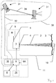
- Fig. 1 illustrates an abstracted view of an embodiment of a handheld surface spattering device 9 which comprises the following parts:
- the expelling characteristics influence the shape and/or direction of the expelled jet of spattering material 2, which can, for example, be defined by parameters like direction, jet-shape, jet-divergence, pressure, speed material rate, emerging speed, aggregate state and/or composition of the expelled spattering material, etc.
- the spattering material 2 (the reference sign actually indicates a jet of expelled spattering material) can be of different nature, e.g. liquid, solid, gaseous or of mixtures of those states. Common examples of spattering materials are paint, finish, lacquer, ink and powder, but also concrete, wax, plastics, asbestos, sand and many more can be expelled.
- the spattering material 2 is supplied to the nozzle means 1 by a spattering material supply 5 which can be embodied as a link to a storage 12, such as a tank or container, which is located at the spattering device 9 or as a pipeline from an external spattering material storage 12.
- the target surface 3 can also be embodied by different objects like sheet metals, walls, floors, grounds, ceilings, roads, machinery, car or airplane bodies, boat hulls, clothes, etc.
- the target surface 3 can also be limited to certain areas of the mentioned objects.
- the target surface can be of any shape and also comprise edges, corners, concavities, obstacles, etc.
- the expelled jet of spattering material 2 which is directed to the target surface 3 results in spots of spattering material 2 on the target surface 3.
- the spot can be characterized by its shape and spot size 10 on the target surface 3 which is dependent on the characteristics of the expelling and the distance 11 between the nozzle means 1 and the target surface 3, as well as on the inclination of the expelling direction relative to the target surface 3.
- the nozzle control mechanism 4 to control the expelling characteristics of ejection of the nozzle means 1 resulting in different expelling characteristics can vary from a simple on/off switching of the expelling to a control of a multiple of the mentioned expelling characteristics by mechanical and/or aerodynamical means which can, for example, be adjusted by motors and/or valves, in particular micro-motors and/or micro-valves.
- the expelling can also be initiated by piezoelectric, thermal or other effects, these can also be influenced by the nozzle control means, as well as for example the pressure or flow rate of the spattering material supply 5.
- the computation means 8 controls or regulates the nozzle control mechanism 4. It can be embodied as a microcontroller, an embedded system, a personal computer or also in form of distributed system where the actual hand held spattering device comprises only a basic computational unit which can establish a communication link to another computation means which can for example have more capacity and performance than the one inside of the handled device, such as a personal computer, laptop or workstation.
- the communication link can be established by wired or wireless means.
- the computation means 8 comprises or is connected to at least one storage which can be embodied as a RAM, ROM, hard disk, memory-card, USB-Stick, or the like, which can be either fixed or removable or a combination of both.
- the storage is built in such a way to memorize the desired spattering data 6, which can be a CAD drawing, vector graphics, a bitmap picture (compressed or uncompressed) and also might even comprise tree dimensional information.
- the spattering data can - beside a two dimensional artwork information - also comprise further information on the three dimensional fitting of the artwork onto the surface.
- Another embodiment which comprises desired spattering data in 3D can build up a three dimensional spattering, in particular by multiple layers of spattering material 2, wherein the previous spattering can be seen as a new target surface 3 for the current spattering, in particular wherein the spattering is applied in multiple layers of spattering material 2.
- the spattering device 9 can be moved in more than three dimensions, which can bring advantage over the known 3D-printers or stereo lithography devices which are based in three orthogonal axes. Therefore, the layers are not restricted to parallel and equidistant slices as in conventional 3D printing, but the layers can be applied from various directions. Therein the actual target surface of each spattering process can be inclined to the previous one.
- a free movement in space of the spattering device 9 can allow applying spattering material 2 from different angles or even from underneath or through wholes which are not accessible by a three axis 3D printing system, wherein complex structures can be built up with a reduced need for supporting webs or bridges which afterwards have to be removed to result in the final 3D product.
- the application of three dimensional structures as desired spattering data can in particular make use of the mentioned methods for curing the spattering material 2.
- the user can be directionally guided in moving the device as discussed above to allow a handheld 3D spattering of highly complex structures from almost any side and angle of the object.
- an erected structure can be built up by spattering approximately from the top, whereas a sideways extension can be applied by spattering approximately from the respective side.
- the direction of spattering does not necessarily has to be perpendicular to the direction of the structural part to be applied by spattering but can also be inclined to a certain extent. Limiting factors are a shadowing of the target surface to be spattered or such a flat spattering angle that the spattering material will not stick on the surface, which both obviously have to be avoided.
- target surface in this embodiment can be a surface of an already created part, sub-part or cross-section of the desired 3D object on which a further building up is required.
- the orientation of such a surface is not limited to parallel planar slices, as in common rapid prototyping systems, but can vary during the spattering process by pointing the spattering device from certain direction, in particular in a direction being approximately at right angles to the surface.
- the three dimensional desired spattering data can also comprise different spattering materials information, for example a body consisting of one material and a surface-finish consisting of a second material, both applied by the same spattering device.
- prior art handheld spattering devices were only capable of applying flat 2D coatings, mostly desired to provide an even and smooth, uniform coating of the target surface.
- the present spattering device can go beyond this, enabling not only a handheld application of desired two dimensional material distributions such a flat images, but also real three dimensional desired spattering patterns in form of reliefs or three dimensional objects.
- the spattering device's position and orientation in space can be used as a basis for calculating the portions of the desired 3D spattering data still to be applied, but also the target object and the already applied parts of the desired spattering data can be observed, scanned or measured for determining the to be applied portion of the desired data and a preferred range of position and orientation of the device from which the application can be executed. Thereby the user can be guided to hold the spattering device in this preferred range of spatial coordinates and orientation for applying a certain portion of the 3D pattern.
- the handheld concept also solves the problem of on sight construction or repair of 3D parts, which would often be advantageous but not possible with the big, inflexible and rigid prior art machinery for 3D printing tasks.
- spattering material e.g. fibre-compounds, thermoplastics, thermoset, sintering powder, or other spattering materials mentioned above, without the requirement of having a positive or negative mould, but just by hand - out of digital three dimensional spattering pattern data of the desired object supplied to the device from some storage means.
- the described curing unit for the spattering material can enable a rapid application of a next layer of material onto the previous one by immediately curing the spattering material after its application.
- a device could also be called a handheld 3D printing unit, which comprises a controlled nozzle means 1 for expelling material 2, a spatial referencing unit and a computation unit 8, with storage for the desired 3D spattering data 6, for controlling the nozzle means 1 according to the spatial reference and the desired spattering data 6.
- the device can further comprise a user guidance means for virtual spatial guidance of a user's hand which is holding the device 9.
- the computation means 8 can also comprise or be connected to one or more human interfaces 26 like a display, screen, projector, touch screen, multi-touch screen, lamp, light, button knob, dial, joystick, speaker, microphone, etc. as well as providing machine interfaces for communication with further technical equipment.
- human interfaces 26 like a display, screen, projector, touch screen, multi-touch screen, lamp, light, button knob, dial, joystick, speaker, microphone, etc. as well as providing machine interfaces for communication with further technical equipment.
- the power for the spattering device 9 can be supplied by a cable or by energy storages such as batteries.
- the device can further be supplied with compressed air and/or spattering material which can be stored at the device or supplied by a remote means.
- the computation means 8 can access spatial information from a spatial referencing unit 30.
- the spatial referencing can take place in a different number of degrees of freedom (DOF), for example in 3D in space with 5 or 6 DOF.
- DOF degrees of freedom
- the referencing can take place in a local coordinate system or in a superordinate or global coordinate system, e.g. by global referencing for outdoor applications.
- the achievable range and the required resolution of the spatial referencing unit 30 depends on the application which the actual spattering device 9 is designed for. This desired range can vary from indoor, local, small area positioning with the expansion of some meters to outdoor, regional or global areas with an expansion of some tens or hundreds of meters for bigger paint projects like sports-grounds or road markings.
- the spatial referencing unit 30 for determining the position and orientation (or pose) according to the invention comprises multiple two dimensional image sensors 31 (also known as photographic or video cameras), in particular CMOS or CCD sensor arrays for detecting optical radiation.
- CMOS or CCD sensor arrays for detecting optical radiation.
- the spatial referencing is achieved by one or more camera(s) 31 for orientation and position determination.
- Such systems are also referred to as vision based tracking systems or stereoscopic systems.
- the cameras 31 are arranged with a stereobasis 39 relative to each other, which means that they are located apart from each other, resulting in different views of the scenery of interest.
- the images of the cameras 31 are capturing at least partially the same scenery, but seen from different locations.
- Based on the stereobasis 39 there are geometrical constraints, which allow to gather 3D information from the multiple images. Therein the same visible feature in each of the image is identified and its respective coordinate within each of the images is determined (for example in picture- or image- coordinates of pixels and preferably subpixels).
- stereobasis 39 is either known by the construction of the spatial referencing unit 30, in particular if their setup is fixed, or can be surveyed or can be calibrated by known reference geometry, in particular if the setup comprises standalone cameras 31 which can be located independently while setting up the spatial referencing unit.
- the spatial referencing 30 unit with its at least two cameras 31 can therefore be embodied as a single device, as multiple devices which each comprises at least one camera 31, or of a set of cameras 31 and a evaluation means 36 that is doing the image processing.
- the image processing can also be done on a remote computation means, for example on the same computation means 8 as used to control the nozzle means.
- the visible features 33 are built in such a way, that they can be identified in the images from the cameras 31, (not necessarily for the human eye). For example, they can provide contrast faces and/or a known shape or geometry for making them identifiable in the image.
- the visible features 33 can be naturally occurring features which are visible and identifiable in the image, for example textures, edges, differently coloured sections, etc. They can also be embodied by artificially applied visual features 33 such as makers attached by means of sticking, magnets, adhesion, suction cups, glue, screws, bolts, clamps, etc.
- the visible features 33 can for example also be light points for example active in form of optical emitters such as light bulbs, LEDs, lasers, fluorescent material, etc which are emitting continuous or pulsed light.
- a single visual feature 33 in particular of unknown shape and size, is in general not sufficient to determine a spatial reference in five or six degrees of freedom a set of multiple visible features is used for referencing by the cameras 31.
- An embodiment of a spattering device 9 can for a example be equipped with an arrangement of multiple LEDs as active visible features 33, wherein the arrangement is built in such a way that its position and orientation can be determined uniquely, for example assisted by blinking codes, different colours, etc.
- an arrangement of passive visual features 33 like on or more geometrical objects of well defined shape and/or colour can be used as visual features. They can also comprise fluorescent or retro reflective surfaces.
- An additional set of visible features 33 can also be present on the target surface 3, in particular when the surface itself does not provides such features, e.g. a uniformly coloured, smooth surface. They can be embodied by stickers, preferably of known shape, colour or texture. It is not necessary to know their shape in advance, if they are identifiable in the images. If the shape and/or size of a feature is known, its appearing size and/or shape in the image can be used for determining further information regarding its distance and/or angle with respect to the camera 31.
- the visible features 33 can alternatively also be attached by magnets, clamps, screws or other means.
- An alternative are also projected light markers, which are projected from the target surface 3 or an object rigidly fixed to it, as their position with respect to the target surface has to be fixes. Such light markers as visible features can be simply over-spattered by the spattering device 9, which might not be possible when sticky markers are used.
- first set of visual features 33 at the spattering device can be a first set of visual features 33 at the spattering device and a second set of visual features 33 at the target surface, whererby the spatial referencing unit 9 with its at least two cameras 31, which is situated remote of the spattering device 9 can reference the spattering device 9 and the target surface 3 relative to each other.
- GPS system which can optionally be aided by an additional sensor 6A like an IMU, a digital compass and/or an inclinometer.
- an IMU an IMU only, which can also optionally be aided by a digital compass and inclinometer.
- a communication link 32 from the remote spatial referencing unit 30 to the computation means 8 which handles the nozzle control mechanism 4 has to be established.
- a real-time communication is used, which allows handling high dynamic movements, in particular in case of a hand guidance of the spattering device 9.
- potentially occurring delays can - at least partially - be compensated by a prediction or a look-ahead, in which case e.g. additional information gathered from an IMU can also be helpful.
- a spattering device 9 can also comprise additional sensor means 6A like rangefinder(s) or distance meter(s) based on radar, ultrasound, light, laser or radio waves which can be used for determining the distance to the target surface or - when using multiple rangefinders can also be used to determine a relative tilt with respect to the target surface.
- the distance-to-surface sensors 6A can be used for both 2D and/or 3D if arranged accordingly.
- the nozzle 1 of the spattering device 9 can also be attached to an articulated arm, a Cartesian guide or another means within the spattering device, that allow to determine the position the spatial measurements of the nozzles position and/or it's orientation within a body of the spattering device 9.
- the spatial referencing unit 30 is then used to determine the position and orientation of the spattering devices body according to the invention, and thereby indirectly also the nozzle 1.
- An embodiment can comprise a passive (which means non-motorized) or active (which means motorized) articulated arm, to which the surface spattering device 9 can be attached.
- the spatial referencing unit 30 is used to reference the arms base relative to the target surface 3 which - together with the articulated arms measurements - allows the calculation of the relative spatial information between the nozzle means 1 and the target surface 3 which information can be comprised in controlling the characteristics of the expelling of the nozzle means 1.
- a digital 3D model of the target surface 3 exists, it is for example also possible to define the target surface 3 by spatially measuring characteristic points of the real world embodiment and matching them to the corresponding 3D model and thereby referencing one or more target surfaces 3 relative to its CAD model.
- Fig. 1 illustrates a spattering device 9 for expelling a singe spattering material 2 or mono colour paint, which is supplied as a pre-mixed spattering material 2 of the desired colour, viscosity, etc. from a spattering material storage 12.
- Fig. 2 shows another abstracted view of an embodiment of graphical application system according to the invention.
- the nozzle means 1 in this figure comprises a mixing of multiple spattering materials 2 inside of the spattering device 9.
- the different spattering materials can then be mixed inside of the nozzle means 1 to a desired composition, being controlled by the nozzle control mechanism 4, for example to achieve the desired colour, which will then be expelled by the nozzle means.
- the dosage of each of the supplied colours can for example be achieved by valves, pumps with variable rate of delivery, or other known means. If required, some additional stirring up can be done to achieve a homogenous mixture.
- the spattering device 9 is capable of expelling a range of colours and also colour transitions automatically.
- the supply 5x can for example comprise solvent which can be mixed to adjust the viscosity of the paint.
- the supply 5x can supply a clear varnish, a special colour which is not achievable by mixing (like black, white, gold, silver, etc.) or other additives to the spattering material, for example to achieve metallic effects, hammered finish, or the like.
- the supply 5x can comprise substances to influence the curing or other characteristics of the spattering material 2.
- the target surface 3 in this illustration comprises a step configuration that can be automatically handled by the nozzle control mechanism 4, which is capable of adjusting the expelling characteristics of the nozzle means 1 to achieve the desired spot diameter on the target surface 3 regardless of the change in distance and inclination introduced by the step. Besides a fully automated adjusting of expelling characteristics, the operator can also be guided or assisted to handle the device in such a way to achieve latter.
- the spatial referencing unit 30 comprises two cameras 31 at a given stereobasis 39.
- the communication link 32 is embodied as a wires communication, symbolized by an antenna.
- the embodiment of the spattering device 9 shown in Fig. 3 is also capable of spattering the target surface 3 which different mixtures of spattering materials 2r, 2g, 2b.
- the main difference with respect to the previous figure is that in this embodiment, there is a separate nozzle means 1 for each spattering material supply 5r, 5g, 5b (5x).
- the actual mixing of the spattering materials 2r, 2b, 2g takes place outside of the nozzle means, either on the way to the target inside the jets of material 2b, 2g, 2r or on the target surface itself by overlapping of the spots of each nozzle on the target surface.
- the desired colour effect can also be achieved without an actual mixing of the spattering material, by aligning separate spots of different spattering material close to each other, so they result in the desired colour impression when watched from distance.
- This method of colour generation is also referred to as dithering in the art of inkjet printing.
- the number of different spattering material supplies 5 and therefore nozzles 1 is not limited to a certain number, but depends on the desired mixtures of spattering materials 2 which have to be achieved, which can for example comprise the colours red, green, blue, black and white to achieve a wide colour range.
- other basic sets of colours as e.g. known from the mixing of colour range of the RAL-colour cards or subsets thereof can be used.
- the different nozzles 1 or one single nozzle 1 can also be used subsequently with different spattering materials 2, e.g. to alternatively apply multiple layers of polyester and fibres automatically in a subsequent manner by the same device.
- the already applied spattering thickness on the target surface 3 can be determined.
- the target surface 3 is inclined relative to the spattering device 9 which, can be detected by the spatial referencing unit 30 and consequently, the nozzle control means 4 can automatically adjust the expelling characteristics of the nozzle means 1 to achieve the desired spattering of the target 3, regardless of the inclination and/or distance and/or to only expel spattering material 2, when the desired result is actually achievable. Therefore, the device 9 can also store information of the already-spattered and/or still-to-spatter areas on the target surface 3.
- the desired spattering data 6 can also comprise or acquire information regarding the hole 14 in the target surface 3. This can for example help to avoid a waste of spattering material 2 and also a soiling of the environment behind the hole 14. Hence, this principle is also applicable to obstructions, irregularities or singularities on the target surface 3 other than holes 14.
- a spattering device 9 comprises a four colour CMYK (cyan, magenta, yellow, black) colouring system according to the invention which is capable of applying a multicolour pattern 15 defined by the desired spattering data 6 onto a target surface 3, e.g. a company's logo onto a building's wall or onto a parking lot.
- CMYK cyan, magenta, yellow, black
- This can be achieved without any masking of undesired spattering areas on the target surface 3, whereby productivity of the spattering process can be improved, since the masking process can be very time consuming and its quality has great impact on the overall spatterwork result.
- the computation means 8 controls the nozzle control mechanism 4 to apply a pattern defined by a desired spattering data 6 onto the target surface 3, by adjusting the expelling characteristics according to the spatial orientation of the spattering device 9 relative to the target surface 3, in particular the relative spatial orientation of each nozzle means 1 to the targeted spot on the target surface 3.
- the nozzle control mechanism 4 can also fine-adjust the direction of expelling or ejection from the nozzle 1, e.g. by tilting the nozzle 1 or by influencing the expelled jet of material 2.
- the computation means 8 is capable of automatically deciding whether or not to release spattering material 2 to the presently targeted spot on the surface 3 or not.
- the presently targeted spot in the expelling direction of the nozzle 1 can also be fine-adjusted by means to deflect the present direction of expelling. The deflection can also compensate the tremor and uncertainties of a hand guiding.
- the nozzle control mechanism 4 can also be capable of adjusting the expelling divergence and/or the amount of expelled material 2 per time.
- the graphical application system is capable of applying multicolour spattering 15 onto a target surface 3, which can be defined by the desired spattering data 6, e.g. provided as a digital artwork or image stored on a memory card.
- a target surface 3 can be defined by the desired spattering data 6, e.g. provided as a digital artwork or image stored on a memory card.
- Such an image can be stored in form of a so called bitmap, comprising a matrix of predefined pixels which are defining spots of spattering material to be applied, and can also include information regarding the desired type or colour of material.
- the image can alternatively be stored in compressed form or in form of vector information (e.g. as in a CAD-file), text information, etc. which can be converted to a desired distribution of spattering material spots on the target surface by the computation means.
- the desired spattering data can be described as digital representation of a desired pattern 6 to be spattered onto the target surface 6, comprising information on multiple areas or sections or subsections of the target surface which have to be spattered with different attributes, in particular different colour, spattering material, thickness, surface condition, etc.
- Fig. 5 illustrates another exemplary embodiment of a graphical application system according to the invention, which comprises a row or line of multiple nozzle means 1.
- the illustration shows nozzles 1 for spattering material 2 mixing as described with respect to Fig. 2 , but also the other described mixing methods are applicable in a row-arrangement in an analogous way.
- the target surface 3 is represented by a car-body (not drawn to scale).
- the bar arrangement can also be used to compensate handling inaccuracies by expelling only from those nozzles 1 which are actually targeting a portion of the surface 3 which has to be spattered according to the desired spattering data 6 while deactivating the other nozzles 1.
- the spattering or painting can take place during production of the car or also in case of repair or replacement of parts of the car's body.
- a colour detection system at or external to the spattering device 9 can be used to determine the present and therefore desired colour of the vehicle to be repaired, which information can then be used to adjust the colour mixing system in the spattering device 9 accordingly to achieve the desired colour.
- the graphical application system can manually, automatically or semi-automatically detect the desired area to be spattered, by the spatial reference measurements and for the arrangement of the desired spattering data.
- the desired area can also be provided in a CAD data model or by detecting or teaching naturally present optical features like borderlines, edges or corners of the desired area to be spattered, e.g. by indicating the contours or edges of a polygon surrounding the desired area or by an optical feature such as a laser spot or a marker applied to the target surface 3.
- the target surface 3 can also be digitalized by the spatial referencing unit 30 and presented as an image or 3d-model on a screen, on which the desired spattering area and/or desired spattering data 6 can be viewed, selected and adjusted in advance of the actual spattering process, either at the spattering device 9 itself or on a remote computer device. Also, special patterns like logos, etc. can be virtually overlaid on the model or image of the target surface 3 by similar means.
- paint recognition sensors 6A are e.g. digital cameras, infrared or ultraviolet cameras or sensors, spectral analyzers, eventually combined with a corresponding illumination system.
- Another option is to equip the device 9 with an electronic display or projection means which allows an overlay of the desired spattering data 6 on a screen or the desired spattering data 6 to be projected onto the target surface 3 by a picture or laser-line projector.
- Fig. 6 shows an embodiment of a graphical application system according to the invention with a handheld spattering device 9 for spattering a target object comprising the target surface 3, where the device is equipped with additional sensor means 6A.
- the illustration shows a previous spattering 21 already present on the surface either for quite a long time or from the previous work session.
- a new spattering 22 needs to be applied to the target surface 3 which can for example be desired to match the colour and surface characteristics of the previous spattering or which can for example be a graphical item to be overlaid on the previous spattering 21.
- a paint recognition sensor 6A can be comprised in or attached to the device 9.
- the camera based spatial referencing unit according to the invention can be used to gather information regarding optical characteristics of the target surface 3. that the cameras are approximated by the pinhole camera model.
- each camera captures a 2D image of the 3D scenery which has to be evaluated.
- the thereby resulting conversion from 3D to 2D can be referred to as a perspective projection.
- a pinhole camera model it is common to model this projection operation by rays that emanate from the camera and passing through a centre of projection, wherein each emanating ray corresponds to a single point in the image.
- the location of the at least two observing 2D cameras can be chosen by providing them fixed to a common base with fixed and predefined position and orientation relative to each other, also known as given stereobasis.
- the graphical application system comprises a spatial referencing unit 30 which requires the setup of at least one base station with a camera 31 external from the spattering device 9.
- the spatial referencing unit 30 from above can optionally be supported by an additional IMU to determine the dynamics of movement, in particular for a hand held device. This information can be combined with the spatial position and orientation measurement of the spatial referencing unit 30.
- the nozzles 1 and nozzle control means 4 are also comprised in the shown spattering device 9, in particular this embodiment comprises a plurality of nozzles 1 in a row-arrangement.
- the illustrated embodiment also comprises one or more spattering material supply(s) 5 and spattering material tank(s) 12. In combination with an energy storage such as a battery and/or a compressed gas tank, this allows the wireless spattering device 9 to be moved freely by hand without any cables and/or supply lines.
- spattering device 9 can be split into an external station (or kind of backpack for a handheld device), comprising the heavier parts like power-supply and spattering material tank 12 which are linked to a lightweight handheld nozzle-device by cables and pipes for lowering the weight to be moved while spattering.
- an arrangement can comprise a support frame attached to the ground, to the target surface or to the operator's body for supporting the device's weight.
- Embodiments of such supports in a handheld embodiment can for example be similar to those in the area of smoothly guiding bulky professional film or video cameras.
- the spattering device 9 can comprise an indication means for user guidance, which assists the user in following a desired path and/or to guide the spattering device 9 to areas which still need to be spattered.
- Such guidance can be achieved by optical, acoustic or haptic means.
- a desired direction indication by LEDs or by symbols on a screen which point to the desired direction.
- an acoustic indication by voice commands or beeps can be used.
- Those indication means can be comprised in the HMI 26 mentioned above.
- An embodiment of a graphical application system according to the invention can also comprise or can be linked to further environmental sensors 6A for determining the local environmental conditions such as temperature, wind speed, humidity, time, and other factors influencing the drying conditions of the spattering material.
- the environmental information gathered by those sensors 6A can be used by the computation means to command the nozzle control mechanism, e.g. in multiple layer painting.
- sensors 6A for analyzing the spattering material like determining its viscosity, flow rate, supply stock, etc.
- the direction of gravity can be taken into account in the determination of desired expelling characteristics.
- An embodiment of the spattering device 9 can be pure manually moved by hand or be at least partly supported by means such as guiding rails, trolley stands, wheeled carts, joint-arms.
- a hand cart for marking sports-fields with chalk-lines comprising a spattering device according to the invention which guides the user to hand-drag it along the desired path of the desired markings by an indication means 26, and automatically corrects minor deviation by the nozzle control means.
- Such a system can for example also be used to accurately apply sports club logos onto grounds or walls by the hand held device 9. This can be done in multi-colour, subsequently for each colour, by loading the spattering device 9 with the desired colour and applying the parts of the logo which require this colour and then loading the next colour.
- Another option is the use of a spattering device 9 comprising an automatic colour mixing and being capable of applying a multi-colour-spattering onto the target surface 3.
- An embodiment of the graphical application system according to the present invention can (in addition to the spatial referencing unit 30) optionally comprise a position, an angle and/or an inertial determination means such as an inertial measurement unit (IMU), Electronic distance meter (EDM), Global positioning system (GPS). It can also comprises additional sensor means 6A for determining target surface 3 properties, in particular spattered and non-spattered areas, present spattering thickness, present surface colour and/or direction of gravity.
- IMU inertial measurement unit
- EDM Electronic distance meter
- GPS Global positioning system
- An embodiment of the surface spattering device 9 can be built in such a way that the target surface 3 is spattered by one or more colour or material 2, wherein the colour or material 2 can be:
- the embodiment of the graphical application system which is shown in Fig. 7 is used for spattering a logo comprised in the desired spattering data onto a curves surface of a cars 26 door.
- the surface spattering device 9 comprises a body 40 or frame 40 within which a nozzle means is positionable by a servo-motor.
- the body 40 is fixed relative to the target surface 3 (in this case to the car).
- the body comprises a set of visible features 33 arranged in such a way, that its position and orientation is determinable by the spatial referencing unit 30, for example as known in the art by different colours, blink codes, an asymmetric arrangement or shape, etc. of the visible features.
- the spatial referencing unit also evaluates visible features 33 of or at the cars 26 body, whereby a spatial referencing of the spattering device 9 to the target surface is established.
- the computation means is controlling the positioning of the nozzle means 1 within the spattering device 9 and also its expelling based on the desired spattering data and the position and orientation information from the spatial referencing unit 30 in order to spatter the desired logo onto the door.
- a handheld spattering device 9 is used, which is spatially referenced by the spatial referencing unit 30 by the thereto attached visual feature 33B in form of a LED arrangement with known geometry.
- the spatial referencing unit also evaluates visible features 33A of the car 26, for example the contours 33A of the door.
- the thereby established position and orientation reference is used by the computation unit to control the nozzle means in such a way, that the desired spattering data is applied to the target location at the door.
- the operator of the spattering device can be guided to follow an optimized path as described above.
- the graphical application system is used to apply a desired pattern 6 to the curved surface of an aircraft 26 by the surface spattering device 9 and the spatial referencing system with the cameras 31.
- the example of the target surface 3 is also on an aircraft vehicle 26.
- a second set of visual features 33A is applied to the target surface 3.
- the visual features 33A at the target surface 3 are projected by the light source 35 stationed at the target surface 3 and remote from the cameras 31 of the spatial referencing unit.
- the cameras 31 are located at different viewing angles to avoid an obstruction of their field of view by the operator of the spattering device 9.
- the more than two cameras 31, are arranged in such a way, that at least two cameras 31 can always observe the visual features 33A and 33B and thereby allowing a valid determination of position and orientation.
- an additional IMU at the spattering device 9 can take over the position and orientation determination. At least for a short time until the obstruction has ended and the spatial referencing system is out malfunction and back to normal operation.
- the IMU can also be involved to assist the camera based spatial referencing for example for gaining additional information of the spattering device's tilt or to compensate for high dynamic movements of the spattering device 9.
- Fig. 11 shows another similar setup of the graphical application system according to the invention.
- the spattering device 9 comprises a body 40 with a therein movable nozzle means.
- the spatial referencing system only has to establish a position and orientation of the spattering device 9 relative to the target 3, according to the visual reference marks 33A,33B at the body of the spattering device 9.
- the spattering device 9 itself can be temporarily attached to the target 3, for example by suction cups, belts, clamps, screws, etc.
- spatterable range of spattering device 9 (given by its positioning system) is spattered, the whole spattering device 9 is detached, relocated at the target surface 3 and attached again. According to the new position and orientation of the spattering device 9, determined by the spatial referencing unit, the spattering can be continued.
- a desired spattering data being larger than the spattering device's range can thereby be applied to the target surface 3 in multiple tiles which are accurately positioned and oriented with respect to each other and to the target surface 3.
- the visual features 33A,33B can also be attached directly to the movable nozzle means and its spatial position and orientation relative to the target is directly determined by the visual spatial referencing unit with the cameras 31.
- the spatial referencing unit comprises a stereographic imaging unit 30 and two additional standalone cameras 31 for enhancing the visual coverage of the spatial referencing system and to gather more redundant data which can be used to enhance accuracy by means of interpolation, a least square fit, etc.
Claims (15)
- Système d'application graphique avec• un dispositif d'éclaboussure de surface (9) comprenant□ au moins une unité de buse (1) pour l'expulsion d'un matériau d'éclaboussure (2) sur une surface cible (3),□ un mécanisme de contrôle de buse (4) pour contrôler des caractéristiques de l'expulsion de l'unité de buse (1) et□ une alimentation en matériau d'éclaboussure (5),• une unité de référencement spatial (30) pour référencer le dispositif d'éclaboussure (10) dans l'espace, en particulier par rapport à la surface cible (3), pour déterminer la position et l'orientation du dispositif d'éclaboussure (9),• un moyen de calcul (8) pour contrôler automatiquement l'expulsion par le mécanisme de contrôle de buse (4) selon l'information obtenue par l'unité de référencement spatial (30) et selon les données d'éclaboussure prédéfinies souhaitées (6) en tant qu'image numérique ou modèle de CAO comprenant une représentation numérique d'un motif souhaité à éclabousser sur la surface cible (3) de telle manière que la surface cible (3) est éclaboussée selon les données d'éclaboussure souhaitées (6) et• un moyen de communication (32) pour établir un lien de communication de l'unité de référencement spatial (30) au moyen de calcul (8) pour fournir la position et l'orientation au moyen de calcul (8),caractérisé en ce que l'unité de référencement spatial (30) est située éloignée du dispositif d'éclaboussure (9) et comprend une unité d'imagerie 3D avec au moins deux caméras optiques 2D (31) arrangées avec une base stéréo (39) entre les caméras (31), l'unité d'imagerie 3D étant conçue pour déterminer la position et l'orientation du dispositif d'éclaboussure (9) par traitement d'image numérique des images prises par les caméras (31) et le dispositif d'éclaboussure (9) comprenant un premier ensemble de caractéristiques visuelles (33, 33B) qui est construit de telle manière que la position et l'orientation du dispositif d'éclaboussure (9) peuvent être déterminées par l'unité de référencement spatial (30) et
l'unité d'imagerie 3D comprenant de plus :- un moyen d'identification construit pour identifier une caractéristique visuelle (33, 33A, 33B) de l'ensemble de caractéristiques visuelles (33, 33B) dans les images,- un moyen de mesure construit pour déterminer des coordonnées d'image de la caractéristique visuelle (33, 33A, 33B) et- un moyen de modélisation 3D construit pour déterminer la position et l'orientation selon les coordonnées d'image et les contraintes géométriques données par la base stéréo (39). - Système d'application graphique selon la revendication 1, caractérisé en ce que la détermination de la référence spatiale est faite dans au moins cinq degrés de liberté.
- Système d'application graphique selon la revendication 1 ou 2, caractérisé en ce que les caractéristiques visuelles (33, 33B) sont des objets de forme géométrique connue qui sont fixés au dispositif d'éclaboussure (9) comme repères et une taille et/ou forme apparente d'une géométrie connue dans les images de caméra est utilisée comme source d'information 3D, en particulier le premier ensemble de caractéristiques visuelles (33B) émettant activement un rayonnement optique.
- Système d'application graphique selon la revendication 1, 2 ou 3, caractérisé en ce qu'un second ensemble de caractéristiques visuelles (33, 33B) est situé sur la surface cible (3), en particulier les caractéristiques visuelles (33, 33B) étant des objets de forme géométrique connue qui sont fixés au dispositif d'éclaboussure (9) comme repères.
- Système d'application graphique selon la revendication 4, caractérisé en ce que les secondes caractéristiques visuelles (33, 33B) sur la surface cibles sont des repères de lumière projetée qui sont projetés à partir d'un endroit avec une position fixe par rapport à la surface cible (3) et laquelle position est délogée de l'unité de référencement spatial (30).
- Système d'application graphique selon l'une quelconque des revendications 1 à 5, caractérisé en ce que le dispositif d'éclaboussure (9) comprend une unité de mesure d'inertie qui est incorporée dans la détermination de la position et de l'orientation, en particulier lorsque l'unité de référencement spatial (30) fonctionne mal de manière temporaire à cause d'une obstruction d'un champ de vision de caméra.
- Système d'application graphique selon l'une quelconque des revendications 1 à 6, caractérisé en ce que le dispositif d'éclaboussure de surface (9) comprend des moyens de capteur supplémentaires (6A) pour déterminer des propriétés de la surface cible (3), en particulier des zones éclaboussées et non éclaboussées, l'épaisseur actuelle de l'éclaboussure, la couleur actuelle de la surface, une condition de séchage du matériau d'éclaboussure (2) étant déterminée et intégrée dans le contrôle des caractéristiques d'expulsion et/ou un télémètre pour évaluer une distance (11) entre l'unité de buse (1) et la surface cible (3).
- Système d'application graphique selon l'une quelconque des revendications 1 à 7, caractérisé en ce que le système d'application est construit pour éclabousser une surface cible (3) non plane, courbée de forme libre selon les données d'éclaboussure souhaitées (6), en particulier pour des corps de véhicules (26) tels que des voitures ou des avions, de préférence les données d'éclaboussure souhaitées (6) comprenant un modèle tridimensionnel de la surface cible (3).
- Système d'application graphique selon l'une quelconque des revendications 1 à 8, caractérisé en ce que le dispositif d'éclaboussure de surface (9) comprend une unité de positionnement pour un positionnement de l'unité de buse (1), en particulier dans au moins deux degrés de liberté, par rapport à un corps (40) du dispositif d'éclaboussure (9), lequel corps (40) comprend des moyens à fixer de manière temporaire dans sa position par rapport à la surface cible (3).
- Système d'application graphique selon la revendication 9 lorsqu'elle dépend de la revendication 4 ou selon quelque revendication dépendant de la revendication 4, caractérisé en ce que le corps (40) est équipé de caractéristiques visuelles (33, 33B) pour l'unité de référencement spatial (30), en particulier lorsque le corps (26) est référencé sur la cible (3) par l'unité de référencement spatial (30) et l'unité de buse (1) est référencée sur le corps (40) par l'unité de positionnement pour un référencement indirect/qui a fait l'objet d'une médiation de l'unité de buse (1) sur la surface cible (3).
- Système d'application graphique selon la revendication 9 ou 10, caractérisé en ce que l'unité de buse (1) est équipée des caractéristiques visuelles (33, 33B) pour l'unité de référencement spatial (30), en particulier lorsque l'unité de buse (1) est référencée directement sur la cible (3) par l'unité de référencement spatial (30).
- Système d'application graphique selon l'une quelconque des revendications 1 à 7, caractérisé en ce que le dispositif d'éclaboussure de surface (9) est portatif et comprend les caractéristiques visuelles (33, 33B) construites de manière à obtenir une référence spatiale identifiable de manière unique du dispositif d'éclaboussure de surface (9) par l'unité de référencement spatial (30).
- Procédé d'application graphique pour éclabousser une surface cible selon des données d'éclaboussure souhaitées par un dispositif d'éclaboussure de surface (9) avec :• référencement spatial du dispositif d'éclaboussure de surface (9) en déterminant la position et l'orientation du dispositif d'éclaboussure (9), en particulier par rapport à une surface cible (3),• acquisition d'un ensemble de données d'éclaboussure souhaitées (6) en lisant une mémorisation comprenant une image numérique ou un modèle de CAO comprenant un motif souhaité à appliquer sur la surface cible (3),• expulsion d'un matériau d'éclaboussure (2) par au moins une unité de buse (1) sur la surface cible (3),• calcul des caractéristiques d'expulsion souhaitées pour le mécanisme de contrôle de buse (4) selon l'information communiquée par le référencement spatial et les données d'éclaboussure souhaitées (6) et• éclaboussure de la surface cible (3) selon les données d'éclaboussure souhaitées (6),caractérisé en ce que le référencement est effectué avec une unité de référencement spatial (30) avec au moins deux caméras 2D (31) arrangées avec une base stéréo (39) et situées éloignées du dispositif d'éclaboussure (9), en déterminant la position et l'orientation selon des images des caméras (31) par traitement d'images numériques, le traitement d'images numériques comprenant- une identification d'une caractéristique visuelle (33, 33A, 33B) d'un premier ensemble de caractéristiques visuelles (33, 33B) dans les images, le premier ensemble de caractéristiques visuelles (33, 33B) étant compris sur le dispositif d'éclaboussure (9) et construit de telle manière que la position et l'orientation du dispositif d'éclaboussure (9) peuvent être déterminées par l'unité de référencement spatial (30),- une détermination de coordonnées d'image de la caractéristique visuelle (33, 33A, 33B) dans les images et- une détermination de position et l'orientation selon les coordonnées d'image et des contraintes géométriques.
- Procédé selon la revendication 13, caractérisé en ce que la position et l'orientation sont déterminées dans au moins cinq degrés de liberté.
- Produit programme d'ordinateur comprenant un code de programme mémorisé sur un support lisible par machine pour calculer les caractéristiques d'expulsion souhaitées d'au moins une unité de buse (1) requise pour éclabousser une surface cible (3) par au moins une couche d'un ou de plusieurs matériaux d'éclaboussure (2) résultant en une éclaboussure de la surface cible (3) selon des données d'éclaboussure souhaitées (6) en commandant un mécanisme de contrôle de buse (4) qui est capable d'ajuster les caractéristiques d'expulsion de l'unité de buse (1) et sur la base de données de référencement spatial de l'unité de buse (1) par rapport à la surface cible (3),
caractérisé en ce que les données de référencement spatial sont calculées par un traitement d'images numériques d'images prises par au moins deux caméras optiques 2D arrangées avec une base stéréo (39) entre les caméras (31) comprenant :- une identification d'une caractéristique visuelle (33, 33A, 33B) dans les images, laquelle caractéristique visuelle (33, 33A, 33B) fait partie d'un premier ensemble de caractéristiques visuelles (33, 33B) sur un dispositif d'éclaboussure (9) qui comprend l'unité de buse (1),- une détermination de coordonnées d'image de la caractéristique visuelle (33, 33A, 33B) et- une modélisation 3D qui détermine la position et l'orientation selon les coordonnées d'image et des contraintes géométriques données par la base stéréo (39).
Priority Applications (6)
| Application Number | Priority Date | Filing Date | Title |
|---|---|---|---|
| EP12160353.4A EP2641661B1 (fr) | 2012-03-20 | 2012-03-20 | Système d'application graphique |
| BRBR102013005874-2A BR102013005874A2 (pt) | 2012-03-20 | 2013-03-12 | Sistema de aplicação gráfica |
| KR1020130028971A KR20130106785A (ko) | 2012-03-20 | 2013-03-19 | 그래픽 적용 시스템 |
| CA2809876A CA2809876C (fr) | 2012-03-20 | 2013-03-19 | Systeme d'application graphique |
| CN201310087427.5A CN103317846B (zh) | 2012-03-20 | 2013-03-19 | 图形应用系统 |
| KR1020150096719A KR101572917B1 (ko) | 2012-03-20 | 2015-07-07 | 그래픽 적용 시스템 |
Applications Claiming Priority (1)
| Application Number | Priority Date | Filing Date | Title |
|---|---|---|---|
| EP12160353.4A EP2641661B1 (fr) | 2012-03-20 | 2012-03-20 | Système d'application graphique |
Publications (2)
| Publication Number | Publication Date |
|---|---|
| EP2641661A1 EP2641661A1 (fr) | 2013-09-25 |
| EP2641661B1 true EP2641661B1 (fr) | 2016-05-11 |
Family
ID=45936843
Family Applications (1)
| Application Number | Title | Priority Date | Filing Date |
|---|---|---|---|
| EP12160353.4A Active EP2641661B1 (fr) | 2012-03-20 | 2012-03-20 | Système d'application graphique |
Country Status (5)
| Country | Link |
|---|---|
| EP (1) | EP2641661B1 (fr) |
| KR (2) | KR20130106785A (fr) |
| CN (1) | CN103317846B (fr) |
| BR (1) | BR102013005874A2 (fr) |
| CA (1) | CA2809876C (fr) |
Cited By (2)
| Publication number | Priority date | Publication date | Assignee | Title |
|---|---|---|---|---|
| FR3123984A1 (fr) * | 2021-06-14 | 2022-12-16 | Airbus Operations (S.A.S.) | Procédé de localisation d’au moins un point d’une pièce réelle sur une maquette numérique |
| US11965107B2 (en) | 2022-07-12 | 2024-04-23 | Axalta Coating Systems Ip Co., Llc | System for applying a coating composition |
Families Citing this family (80)
| Publication number | Priority date | Publication date | Assignee | Title |
|---|---|---|---|---|
| EP2799150B1 (fr) | 2013-05-02 | 2016-04-27 | Hexagon Technology Center GmbH | Système d'application graphique |
| US9254640B2 (en) | 2012-07-25 | 2016-02-09 | Nike, Inc. | Projector assisted alignment and printing |
| US8978551B2 (en) * | 2012-07-25 | 2015-03-17 | Nike, Inc. | Projection assisted printer alignment using remote device |
| US9070055B2 (en) | 2012-07-25 | 2015-06-30 | Nike, Inc. | Graphic alignment for printing to an article using a first display device and a second display device |
| FR3010918B1 (fr) * | 2013-09-23 | 2019-07-26 | Airbus Operations | Dispositif pour l'application de revetements projetes sur des pieces et procede associe |
| EP2887011B1 (fr) * | 2013-12-20 | 2017-02-08 | Hexagon Technology Center GmbH | Machine de mesure de coordonnées dotée d'une fonctionnalité d'impression 3D haute précision |
| CN103934171B (zh) * | 2013-12-31 | 2016-06-01 | 浙江吉利控股集团有限公司 | 一种打胶台 |
| TWI491496B (zh) * | 2014-05-08 | 2015-07-11 | 三緯國際立體列印科技股份有限公司 | 立體列印裝置及其列印校正板與立體列印校正方法 |
| CN103990571B (zh) * | 2014-05-22 | 2017-01-04 | 北京铭隆世纪科技有限公司 | 自动喷漆的实现方法及装置 |
| US9677942B2 (en) * | 2014-10-30 | 2017-06-13 | Axalta Coating Systems IP Co. LLC | System and method for measuring color using location and orientation sensors |
| JP6561462B2 (ja) * | 2014-12-19 | 2019-08-21 | カシオ計算機株式会社 | ネイルプリント装置及びネイルプリント装置の描画方法 |
| US10324428B2 (en) * | 2015-02-12 | 2019-06-18 | Carlisle Fluid Technologies, Inc. | Intra-shop connectivity system |
| DE102016204123A1 (de) * | 2015-04-16 | 2016-10-20 | Heidelberger Druckmaschinen Ag | Verfahren zum Bedrucken eines Objekts mit einem Druckbild |
| GB2573061B (en) * | 2015-06-22 | 2020-03-11 | Q Bot Ltd | Robotic vehicle |
| GB2539661B (en) | 2015-06-22 | 2019-06-26 | Q Bot Ltd | Robotic Vehicle |
| DE102015216026A1 (de) * | 2015-08-21 | 2017-02-23 | Krones Ag | Direktdruckmaschine und Verfahren zur Bedruckung von Behältern mit einem Direktdruck |
| EP3370884A1 (fr) * | 2015-11-04 | 2018-09-12 | Sprayprinter Oü | Imprimante à pulvérisation basée sur une application sans fil et système de peinture de surface |
| EP3223200A1 (fr) | 2016-03-22 | 2017-09-27 | Hexagon Technology Center GmbH | Gestion de chantier de construction |
| WO2017191225A1 (fr) * | 2016-05-03 | 2017-11-09 | Sprayprinter Oü | Dispositif d'impression par pulvérisation sans fil destiné à la peinture ou la décoration de surfaces |
| CN105923162A (zh) * | 2016-06-17 | 2016-09-07 | 苏州大学 | 一种无人机自动喷绘装置 |
| CN107718896B (zh) * | 2016-08-13 | 2019-05-24 | 北京林业大学 | 大地打印系统和方法 |
| US11035667B2 (en) * | 2016-09-14 | 2021-06-15 | Erez Halahmi | Monitoring system and method for controlling process of surface treatment for construction |
| CN107825444A (zh) * | 2016-09-16 | 2018-03-23 | 天津思博科科技发展有限公司 | 基于机器视觉技术的表面帖装机器手 |
| DE102016123731B4 (de) | 2016-12-07 | 2019-03-21 | Pixelrunner GmbH | Roboter zum Drucken von Bildern auf Bodenflächen |
| DE102016014948A1 (de) | 2016-12-14 | 2018-06-14 | Dürr Systems Ag | Druckkopf und zugehöriges Betriebsverfahren |
| DE102016014944A1 (de) | 2016-12-14 | 2018-06-14 | Dürr Systems Ag | Beschichtungsverfahren und entsprechende Beschichtungseinrichtung |
| DE102016014956A1 (de) | 2016-12-14 | 2018-06-14 | Dürr Systems Ag | Beschichtungseinrichtung und zugehöriges Betriebsverfahren |
| DE102016014947A1 (de) | 2016-12-14 | 2018-06-14 | Dürr Systems Ag | Druckkopf zur Applikation eines Beschichtungsmittels |
| DE102016014955A1 (de) | 2016-12-14 | 2018-06-14 | Dürr Systems Ag | Beschichtungseinrichtung und entsprechendes Beschichtungsverfahren |
| DE102016014943A1 (de) | 2016-12-14 | 2018-06-14 | Dürr Systems Ag | Druckkopf mit Temperiereinrichtung |
| DE102016014951A1 (de) | 2016-12-14 | 2018-06-14 | Dürr Systems Ag | Beschichtungseinrichtung und zugehöriges Betriebsverfahren |
| DE102016014919A1 (de) | 2016-12-14 | 2018-06-14 | Dürr Systems Ag | Applikationsvorrichtung und Verfahren zum Applizieren eines Beschichtungsmittels |
| DE102016014946A1 (de) | 2016-12-14 | 2018-06-14 | Dürr Systems Ag | Druckkopf zur Applikation eines Beschichtungsmittels auf ein Bauteil |
| DE102016014952A1 (de) | 2016-12-14 | 2018-06-14 | Dürr Systems Ag | Beschichtungseinrichtung zur Beschichtung von Bauteilen |
| WO2018185892A1 (fr) * | 2017-04-05 | 2018-10-11 | 株式会社ニコン | Dispositif de détection de position et système d'aide à la peinture |
| FR3067624B1 (fr) * | 2017-06-19 | 2021-12-17 | Addup | Calibration d'un systeme de tete d'une source de rayonnement de puissance d'un appareil de fabrication additive |
| CN107282385A (zh) * | 2017-07-17 | 2017-10-24 | 苏州歌德尔自动化有限公司 | 一种键盘基板喷涂工艺方法 |
| DE102017212751A1 (de) * | 2017-07-25 | 2019-01-31 | Robert Bosch Gmbh | Zeichenvorrichtung mit einer Projektionseinheit |
| CN107335571A (zh) * | 2017-08-25 | 2017-11-10 | 无锡康柏斯机械科技有限公司 | 一种大型罐体内壁防腐层喷涂装置 |
| DE102017215725A1 (de) | 2017-09-07 | 2019-03-07 | Bayerische Motoren Werke Aktiengesellschaft | Vorrichtung und Verfahren zur Applikation eines Dicht- und/oder Beschichtungsstoffes |
| BR112020007942B1 (pt) * | 2017-10-25 | 2023-11-14 | Nikon Corporation | Aparelho de processamento |
| CN114643189B (zh) * | 2017-11-30 | 2023-05-23 | 艾仕得涂料系统有限责任公司 | 利用高转移效率施涂器施加的涂料组合物及其方法和系统 |
| DE102018220405A1 (de) * | 2017-12-06 | 2019-06-06 | Robert Bosch Gmbh | Medienauftragsvorrichtung |
| DE102018220412A1 (de) * | 2017-12-06 | 2019-06-06 | Robert Bosch Gmbh | Medienauftragsvorrichtung |
| DE102018220409A1 (de) * | 2017-12-06 | 2019-06-06 | Robert Bosch Gmbh | Medienauftragsvorrichtung |
| JP6718429B2 (ja) * | 2017-12-22 | 2020-07-08 | 株式会社Subaru | 画像投影装置 |
| CN108031588A (zh) * | 2017-12-29 | 2018-05-15 | 深圳海桐防务装备技术有限责任公司 | 自动喷涂装置及使用其的自动喷涂方法 |
| JP7271956B2 (ja) | 2018-01-16 | 2023-05-12 | 株式会社リコー | 弁型ノズル及び液体を吐出する装置 |
| DE102018110742A1 (de) * | 2018-05-04 | 2019-11-07 | Liebherr-Werk Biberach Gmbh | Verfahren und Vorrichtung zum Warten und/oder Reparieren einer Baumaschine |
| DE102018111315A1 (de) * | 2018-05-11 | 2019-11-14 | Khs Gmbh | Etikettenkasten |
| JP7121622B2 (ja) * | 2018-09-28 | 2022-08-18 | 芝浦メカトロニクス株式会社 | 錠剤印刷装置及び錠剤印刷方法 |
| US10828889B2 (en) * | 2018-10-05 | 2020-11-10 | Southwest Research Institute | Printing using an externally generated reference |
| US11465353B2 (en) * | 2018-11-30 | 2022-10-11 | Photofusion Technologies Limited | High mobility 3D laser printing system |
| US10940698B2 (en) * | 2019-02-22 | 2021-03-09 | Xyrec Ip B.V. | System and method for high accuracy printing on a 3D surface |
| US11207896B2 (en) * | 2019-02-22 | 2021-12-28 | Xyrec Ip B.V. | High accuracy printing on a curved surface using fiducial markers and a camera |
| JP6807112B2 (ja) * | 2019-04-18 | 2021-01-06 | 紀州技研工業株式会社 | 印字条件の設定方法および印字システム |
| FI128483B (en) | 2019-04-25 | 2020-06-15 | Novatron Oy | Measuring arrangement for measuring the three-dimensional position and orientation of the central axis of the first axis with respect to the central axis of the second axis |
| IT201900008499A1 (it) * | 2019-06-10 | 2020-12-10 | Nicola Cristiano Zonno | Processo e sistema di produzione di oggetti decorati |
| JP6783365B1 (ja) * | 2019-09-20 | 2020-11-11 | 株式会社大気社 | 塗装方法、塗装装置、および塗装プログラム |
| CN110961284A (zh) * | 2019-10-25 | 2020-04-07 | 上海魅奈儿科技有限公司 | 一种自动喷涂装置及方法 |
| AU2020397056A1 (en) * | 2019-12-06 | 2022-06-09 | Graco Minnesota Inc. | Automated mobile sprayer spraying and navigation |
| CN111299013A (zh) * | 2020-02-15 | 2020-06-19 | 上海万林机械制造有限公司 | 一种影射轮廓识别清洗喷涂系统 |
| EP3875992A1 (fr) * | 2020-03-04 | 2021-09-08 | Hexagon Technology Center GmbH | Amélioration du balayage gpr par l'utilisation des connaissances de la scène externe |
| CN111487994B (zh) * | 2020-04-26 | 2020-11-27 | 湖北省工业建筑集团安装工程有限公司 | 基于无人机的超大型高层建筑补漆方法 |
| WO2021225140A1 (fr) * | 2020-05-08 | 2021-11-11 | ファナック株式会社 | Simulateur |
| WO2021255896A1 (fr) * | 2020-06-18 | 2021-12-23 | アーベーベー・シュバイツ・アーゲー | Robot de peinture et procédé de peinture mettant en œuvre le robot de peinture |
| CN111653184B (zh) * | 2020-07-10 | 2022-05-10 | 宿迁市规划测绘院有限公司 | 一种拥有多功能放置台的3d地图批量喷绘控制系统 |
| CN111831778B (zh) * | 2020-07-23 | 2023-06-20 | 湖北玖誉土地评估勘测有限公司 | 一种三维地理信息系统快速集成展现的方法 |
| CN112381710A (zh) * | 2020-10-13 | 2021-02-19 | 中铭谷智能机器人(广东)有限公司 | 一种用于汽车钣喷的2d视觉算法系统 |
| EP3984760A1 (fr) * | 2020-10-14 | 2022-04-20 | Ricoh Company, Ltd. | Appareil de décharge de liquide et méthode de décharge de liquide |
| CN112275496B (zh) * | 2020-10-29 | 2022-04-01 | 上海应用技术大学 | 实验用导轨式自动喷涂机 |
| CN113289793A (zh) * | 2021-05-11 | 2021-08-24 | 山东华锐智能技术有限公司 | 适用于钢构件自动喷涂装置的轨迹实时提取方法 |
| CN113267143B (zh) * | 2021-06-30 | 2023-08-29 | 三一建筑机器人(西安)研究院有限公司 | 边模识别方法 |
| CN113522664B (zh) * | 2021-07-12 | 2022-11-25 | 哈尔滨汽轮机厂有限责任公司 | 一种汽轮机热喷涂路径规划方法 |
| CN114029957A (zh) * | 2021-12-10 | 2022-02-11 | 渭南陕煤启辰科技有限公司 | 一种喷浆机器人智能控制系统 |
| DE102022101538A1 (de) | 2022-01-24 | 2023-07-27 | Homag Gmbh | Verfahren zum Auftragen oberflächenmanipulierender Fluide auf eine Oberfläche eines Werkstücks und Auftragseinrichtung |
| CN114753598B (zh) * | 2022-05-24 | 2023-11-03 | 良固建筑工程(上海)有限公司 | 中空内模墙体的喷涂厚度智能控制方法 |
| PL441339A1 (pl) * | 2022-06-01 | 2023-12-04 | Suchar Tools Spółka Z Ograniczoną Odpowiedzialnością | Sposób i układ do nanoszenia powłok |
| JP7143053B1 (ja) * | 2022-06-09 | 2022-09-28 | Dmg森精機株式会社 | 情報処理装置およびプログラム |
| CN115591698A (zh) * | 2022-10-31 | 2023-01-13 | 重庆长安汽车股份有限公司(Cn) | 一种基于汽车涂装生产双线的车身智能放行控制方法及系统 |
Citations (1)
| Publication number | Priority date | Publication date | Assignee | Title |
|---|---|---|---|---|
| US20050100680A1 (en) * | 2002-01-24 | 2005-05-12 | Burkhard Bustgens | Method for applying paints and varnishes |
Family Cites Families (20)
| Publication number | Priority date | Publication date | Assignee | Title |
|---|---|---|---|---|
| JPH10264060A (ja) | 1997-03-27 | 1998-10-06 | Trinity Ind Corp | 塗装ロボットのティーチング装置 |
| US5935657A (en) | 1997-11-25 | 1999-08-10 | Melendez; Henry | Multiple nozzle paint spray apparatus and method for painting a surface |
| FR2785230B1 (fr) | 1998-10-30 | 2001-08-10 | Jean Pierre Leblanc | Procede et equipement de realisation d'un dessin sur le sol |
| US6074693A (en) | 1999-02-22 | 2000-06-13 | Trimble Navigation Limited | Global positioning system controlled paint sprayer |
| CN2421082Y (zh) * | 2000-05-24 | 2001-02-28 | 浙江航宇实业有限公司 | 手提喷塑枪 |
| DE10138167A1 (de) * | 2001-08-03 | 2003-02-27 | Saremo Objektfinish Ag | Vorrichtung und Verfahren für ein gezieltes Auftragen von Beschichtungsmaterial |
| FR2850322B1 (fr) | 2003-01-23 | 2006-12-15 | Francois Bancel | Dispositif d'impression d'une image sur une grande surface |
| US7687099B2 (en) * | 2003-08-21 | 2010-03-30 | Bae Systems Plc | Spray coating |
| KR20060009588A (ko) | 2004-07-26 | 2006-02-01 | (주)미테크노 | 도색용 다관절로봇의 분사위치 조정방법 |
| US7350890B2 (en) | 2004-08-26 | 2008-04-01 | The Boeing Company | Apparatus and methods for applying images to a surface |
| DE102005003333A1 (de) | 2005-01-25 | 2006-07-27 | Büstgens, Burkhard, Dr.-Ing. | Verfahren für den positionsabhängigen Farbauftrag auf konturierten Flächen |
| JP2006320825A (ja) | 2005-05-18 | 2006-11-30 | Fuji Heavy Ind Ltd | 自動制御塗装車両 |
| US7342670B2 (en) * | 2005-10-19 | 2008-03-11 | Labcoat, Ltd. | In-flight drop location verification system |
| KR100812725B1 (ko) | 2006-10-23 | 2008-03-12 | 삼성중공업 주식회사 | 도장로봇의 위치 각도 제어 방법 |
| US8584973B2 (en) * | 2007-10-31 | 2013-11-19 | Nordson Corporation | Powder coating gun with manually operated controls on gun |
| US20090179081A1 (en) * | 2008-01-15 | 2009-07-16 | Illinois Tool Works Inc. | Spray Gun with Low Emissions Technology |
| DE102008015258B4 (de) | 2008-03-20 | 2023-05-25 | Dürr Systems Ag | Farbwechsler für einen Lackierroboter |
| US7922272B2 (en) | 2008-04-11 | 2011-04-12 | The Boeing Company | Method for application and accurate positioning of graphics on a surface |
| DE102009021608B4 (de) * | 2009-05-15 | 2015-10-15 | Airbus Operations Gmbh | Einrichtung und Verfahren zum Lackieren gekrümmter Außenoberflächen eines Luftfahrzeuges |
| EP2433716A1 (fr) * | 2010-09-22 | 2012-03-28 | Hexagon Technology Center GmbH | Dispositif d'éclaboussure de surfaces avec un mécanisme de régulation de buse et procédé correspondant |
-
2012
- 2012-03-20 EP EP12160353.4A patent/EP2641661B1/fr active Active
-
2013
- 2013-03-12 BR BRBR102013005874-2A patent/BR102013005874A2/pt active Search and Examination
- 2013-03-19 KR KR1020130028971A patent/KR20130106785A/ko active Application Filing
- 2013-03-19 CA CA2809876A patent/CA2809876C/fr not_active Expired - Fee Related
- 2013-03-19 CN CN201310087427.5A patent/CN103317846B/zh active Active
-
2015
- 2015-07-07 KR KR1020150096719A patent/KR101572917B1/ko active IP Right Grant
Patent Citations (1)
| Publication number | Priority date | Publication date | Assignee | Title |
|---|---|---|---|---|
| US20050100680A1 (en) * | 2002-01-24 | 2005-05-12 | Burkhard Bustgens | Method for applying paints and varnishes |
Cited By (3)
| Publication number | Priority date | Publication date | Assignee | Title |
|---|---|---|---|---|
| FR3123984A1 (fr) * | 2021-06-14 | 2022-12-16 | Airbus Operations (S.A.S.) | Procédé de localisation d’au moins un point d’une pièce réelle sur une maquette numérique |
| EP4105595A1 (fr) * | 2021-06-14 | 2022-12-21 | Airbus Operations (S.A.S.) | Procédé de localisation d'au moins un point d'une pièce réelle sur une maquette numérique |
| US11965107B2 (en) | 2022-07-12 | 2024-04-23 | Axalta Coating Systems Ip Co., Llc | System for applying a coating composition |
Also Published As
| Publication number | Publication date |
|---|---|
| EP2641661A1 (fr) | 2013-09-25 |
| CN103317846A (zh) | 2013-09-25 |
| BR102013005874A2 (pt) | 2015-08-04 |
| KR101572917B1 (ko) | 2015-12-02 |
| CA2809876A1 (fr) | 2013-09-20 |
| KR20150086219A (ko) | 2015-07-27 |
| CA2809876C (fr) | 2016-02-09 |
| CN103317846B (zh) | 2016-05-11 |
| KR20130106785A (ko) | 2013-09-30 |
Similar Documents
| Publication | Publication Date | Title |
|---|---|---|
| EP2641661B1 (fr) | Système d'application graphique | |
| US8875655B2 (en) | Graphical application system | |
| EP2799150B1 (fr) | Système d'application graphique | |
| Asadi et al. | Pictobot: A cooperative painting robot for interior finishing of industrial developments | |
| EP1627338B1 (fr) | Marquage de surfaces larges avec des presentations visuelles | |
| CN102806178A (zh) | 自动获取喷涂定位尺寸的喷涂系统及其喷涂方法 | |
| CN104525422A (zh) | 一种控制喷涂机器人路径的方法 | |
| CN104549850A (zh) | 一种控制喷涂机器人喷枪的方法 | |
| CN104525423A (zh) | 一种控制喷涂机器人的喷涂方法 | |
| CA3062036A1 (fr) | Systeme d'impression robotique de logo publicitaire | |
| TWM544995U (zh) | 三維噴塗系統 | |
| WO2018185893A1 (fr) | Dispositif d'extraction de zone non mesurée, dispositif de guidage de travail et procédé de guidage de travail | |
| KR102492690B1 (ko) | 선체 도장 로봇용 드론 시스템 | |
| AT517924B1 (de) | Markiersystem | |
| WO2018185892A1 (fr) | Dispositif de détection de position et système d'aide à la peinture |
Legal Events
| Date | Code | Title | Description |
|---|---|---|---|
| PUAI | Public reference made under article 153(3) epc to a published international application that has entered the european phase |
Free format text: ORIGINAL CODE: 0009012 |
|
| AK | Designated contracting states |
Kind code of ref document: A1 Designated state(s): AL AT BE BG CH CY CZ DE DK EE ES FI FR GB GR HR HU IE IS IT LI LT LU LV MC MK MT NL NO PL PT RO RS SE SI SK SM TR |
|
| AX | Request for extension of the european patent |
Extension state: BA ME |
|
| 17P | Request for examination filed |
Effective date: 20140218 |
|
| RBV | Designated contracting states (corrected) |
Designated state(s): AL AT BE BG CH CY CZ DE DK EE ES FI FR GB GR HR HU IE IS IT LI LT LU LV MC MK MT NL NO PL PT RO RS SE SI SK SM TR |
|
| RIN1 | Information on inventor provided before grant (corrected) |
Inventor name: SIERCKS, KNUT Inventor name: ZEBHAUSER, BENEDIKT Inventor name: PETTERSSON, BO Inventor name: SCHNEIDER, KLAUS |
|
| RIC1 | Information provided on ipc code assigned before grant |
Ipc: B05B 12/00 20060101ALI20151016BHEP Ipc: B05B 12/12 20060101AFI20151016BHEP Ipc: G01B 11/03 20060101ALN20151016BHEP |
|
| RIC1 | Information provided on ipc code assigned before grant |
Ipc: B05B 12/00 20060101ALI20151026BHEP Ipc: G01B 11/03 20060101ALN20151026BHEP Ipc: B05B 12/12 20060101AFI20151026BHEP |
|
| GRAP | Despatch of communication of intention to grant a patent |
Free format text: ORIGINAL CODE: EPIDOSNIGR1 |
|
| INTG | Intention to grant announced |
Effective date: 20151208 |
|
| GRAS | Grant fee paid |
Free format text: ORIGINAL CODE: EPIDOSNIGR3 |
|
| GRAA | (expected) grant |
Free format text: ORIGINAL CODE: 0009210 |
|
| AK | Designated contracting states |
Kind code of ref document: B1 Designated state(s): AL AT BE BG CH CY CZ DE DK EE ES FI FR GB GR HR HU IE IS IT LI LT LU LV MC MK MT NL NO PL PT RO RS SE SI SK SM TR |
|
| REG | Reference to a national code |
Ref country code: GB Ref legal event code: FG4D |
|
| REG | Reference to a national code |
Ref country code: CH Ref legal event code: EP |
|
| REG | Reference to a national code |
Ref country code: AT Ref legal event code: REF Ref document number: 798215 Country of ref document: AT Kind code of ref document: T Effective date: 20160515 |
|
| REG | Reference to a national code |
Ref country code: IE Ref legal event code: FG4D |
|
| REG | Reference to a national code |
Ref country code: CH Ref legal event code: NV Representative=s name: KAMINSKI HARMANN PATENTANWAELTE AG, LI |
|
| REG | Reference to a national code |
Ref country code: DE Ref legal event code: R096 Ref document number: 602012018251 Country of ref document: DE |
|
| REG | Reference to a national code |
Ref country code: SE Ref legal event code: TRGR |
|
| REG | Reference to a national code |
Ref country code: NL Ref legal event code: FP |
|
| REG | Reference to a national code |
Ref country code: LT Ref legal event code: MG4D |
|
| PG25 | Lapsed in a contracting state [announced via postgrant information from national office to epo] |
Ref country code: NO Free format text: LAPSE BECAUSE OF FAILURE TO SUBMIT A TRANSLATION OF THE DESCRIPTION OR TO PAY THE FEE WITHIN THE PRESCRIBED TIME-LIMIT Effective date: 20160811 Ref country code: FI Free format text: LAPSE BECAUSE OF FAILURE TO SUBMIT A TRANSLATION OF THE DESCRIPTION OR TO PAY THE FEE WITHIN THE PRESCRIBED TIME-LIMIT Effective date: 20160511 Ref country code: LT Free format text: LAPSE BECAUSE OF FAILURE TO SUBMIT A TRANSLATION OF THE DESCRIPTION OR TO PAY THE FEE WITHIN THE PRESCRIBED TIME-LIMIT Effective date: 20160511 |
|
| REG | Reference to a national code |
Ref country code: AT Ref legal event code: MK05 Ref document number: 798215 Country of ref document: AT Kind code of ref document: T Effective date: 20160511 |
|
| PG25 | Lapsed in a contracting state [announced via postgrant information from national office to epo] |
Ref country code: ES Free format text: LAPSE BECAUSE OF FAILURE TO SUBMIT A TRANSLATION OF THE DESCRIPTION OR TO PAY THE FEE WITHIN THE PRESCRIBED TIME-LIMIT Effective date: 20160511 Ref country code: HR Free format text: LAPSE BECAUSE OF FAILURE TO SUBMIT A TRANSLATION OF THE DESCRIPTION OR TO PAY THE FEE WITHIN THE PRESCRIBED TIME-LIMIT Effective date: 20160511 Ref country code: LV Free format text: LAPSE BECAUSE OF FAILURE TO SUBMIT A TRANSLATION OF THE DESCRIPTION OR TO PAY THE FEE WITHIN THE PRESCRIBED TIME-LIMIT Effective date: 20160511 Ref country code: RS Free format text: LAPSE BECAUSE OF FAILURE TO SUBMIT A TRANSLATION OF THE DESCRIPTION OR TO PAY THE FEE WITHIN THE PRESCRIBED TIME-LIMIT Effective date: 20160511 Ref country code: GR Free format text: LAPSE BECAUSE OF FAILURE TO SUBMIT A TRANSLATION OF THE DESCRIPTION OR TO PAY THE FEE WITHIN THE PRESCRIBED TIME-LIMIT Effective date: 20160812 Ref country code: PT Free format text: LAPSE BECAUSE OF FAILURE TO SUBMIT A TRANSLATION OF THE DESCRIPTION OR TO PAY THE FEE WITHIN THE PRESCRIBED TIME-LIMIT Effective date: 20160912 |
|
| PG25 | Lapsed in a contracting state [announced via postgrant information from national office to epo] |
Ref country code: IT Free format text: LAPSE BECAUSE OF FAILURE TO SUBMIT A TRANSLATION OF THE DESCRIPTION OR TO PAY THE FEE WITHIN THE PRESCRIBED TIME-LIMIT Effective date: 20160511 |
|
| PG25 | Lapsed in a contracting state [announced via postgrant information from national office to epo] |
Ref country code: DK Free format text: LAPSE BECAUSE OF FAILURE TO SUBMIT A TRANSLATION OF THE DESCRIPTION OR TO PAY THE FEE WITHIN THE PRESCRIBED TIME-LIMIT Effective date: 20160511 Ref country code: CZ Free format text: LAPSE BECAUSE OF FAILURE TO SUBMIT A TRANSLATION OF THE DESCRIPTION OR TO PAY THE FEE WITHIN THE PRESCRIBED TIME-LIMIT Effective date: 20160511 Ref country code: RO Free format text: LAPSE BECAUSE OF FAILURE TO SUBMIT A TRANSLATION OF THE DESCRIPTION OR TO PAY THE FEE WITHIN THE PRESCRIBED TIME-LIMIT Effective date: 20160511 Ref country code: SK Free format text: LAPSE BECAUSE OF FAILURE TO SUBMIT A TRANSLATION OF THE DESCRIPTION OR TO PAY THE FEE WITHIN THE PRESCRIBED TIME-LIMIT Effective date: 20160511 Ref country code: EE Free format text: LAPSE BECAUSE OF FAILURE TO SUBMIT A TRANSLATION OF THE DESCRIPTION OR TO PAY THE FEE WITHIN THE PRESCRIBED TIME-LIMIT Effective date: 20160511 |
|
| REG | Reference to a national code |
Ref country code: DE Ref legal event code: R097 Ref document number: 602012018251 Country of ref document: DE |
|
| PG25 | Lapsed in a contracting state [announced via postgrant information from national office to epo] |
Ref country code: SM Free format text: LAPSE BECAUSE OF FAILURE TO SUBMIT A TRANSLATION OF THE DESCRIPTION OR TO PAY THE FEE WITHIN THE PRESCRIBED TIME-LIMIT Effective date: 20160511 Ref country code: PL Free format text: LAPSE BECAUSE OF FAILURE TO SUBMIT A TRANSLATION OF THE DESCRIPTION OR TO PAY THE FEE WITHIN THE PRESCRIBED TIME-LIMIT Effective date: 20160511 Ref country code: BE Free format text: LAPSE BECAUSE OF FAILURE TO SUBMIT A TRANSLATION OF THE DESCRIPTION OR TO PAY THE FEE WITHIN THE PRESCRIBED TIME-LIMIT Effective date: 20160511 Ref country code: AT Free format text: LAPSE BECAUSE OF FAILURE TO SUBMIT A TRANSLATION OF THE DESCRIPTION OR TO PAY THE FEE WITHIN THE PRESCRIBED TIME-LIMIT Effective date: 20160511 |
|
| PLBE | No opposition filed within time limit |
Free format text: ORIGINAL CODE: 0009261 |
|
| STAA | Information on the status of an ep patent application or granted ep patent |
Free format text: STATUS: NO OPPOSITION FILED WITHIN TIME LIMIT |
|
| REG | Reference to a national code |
Ref country code: FR Ref legal event code: PLFP Year of fee payment: 6 |
|
| 26N | No opposition filed |
Effective date: 20170214 |
|
| PG25 | Lapsed in a contracting state [announced via postgrant information from national office to epo] |
Ref country code: SI Free format text: LAPSE BECAUSE OF FAILURE TO SUBMIT A TRANSLATION OF THE DESCRIPTION OR TO PAY THE FEE WITHIN THE PRESCRIBED TIME-LIMIT Effective date: 20160511 |
|
| PG25 | Lapsed in a contracting state [announced via postgrant information from national office to epo] |
Ref country code: MC Free format text: LAPSE BECAUSE OF FAILURE TO SUBMIT A TRANSLATION OF THE DESCRIPTION OR TO PAY THE FEE WITHIN THE PRESCRIBED TIME-LIMIT Effective date: 20160511 |
|
| REG | Reference to a national code |
Ref country code: IE Ref legal event code: MM4A |
|
| PG25 | Lapsed in a contracting state [announced via postgrant information from national office to epo] |
Ref country code: LU Free format text: LAPSE BECAUSE OF NON-PAYMENT OF DUE FEES Effective date: 20170320 |
|
| PG25 | Lapsed in a contracting state [announced via postgrant information from national office to epo] |
Ref country code: IE Free format text: LAPSE BECAUSE OF NON-PAYMENT OF DUE FEES Effective date: 20170320 |
|
| REG | Reference to a national code |
Ref country code: FR Ref legal event code: PLFP Year of fee payment: 7 |
|
| PG25 | Lapsed in a contracting state [announced via postgrant information from national office to epo] |
Ref country code: MT Free format text: LAPSE BECAUSE OF NON-PAYMENT OF DUE FEES Effective date: 20170320 |
|
| PG25 | Lapsed in a contracting state [announced via postgrant information from national office to epo] |
Ref country code: AL Free format text: LAPSE BECAUSE OF FAILURE TO SUBMIT A TRANSLATION OF THE DESCRIPTION OR TO PAY THE FEE WITHIN THE PRESCRIBED TIME-LIMIT Effective date: 20160511 |
|
| PG25 | Lapsed in a contracting state [announced via postgrant information from national office to epo] |
Ref country code: HU Free format text: LAPSE BECAUSE OF FAILURE TO SUBMIT A TRANSLATION OF THE DESCRIPTION OR TO PAY THE FEE WITHIN THE PRESCRIBED TIME-LIMIT; INVALID AB INITIO Effective date: 20120320 |
|
| PG25 | Lapsed in a contracting state [announced via postgrant information from national office to epo] |
Ref country code: BG Free format text: LAPSE BECAUSE OF FAILURE TO SUBMIT A TRANSLATION OF THE DESCRIPTION OR TO PAY THE FEE WITHIN THE PRESCRIBED TIME-LIMIT Effective date: 20160511 |
|
| PG25 | Lapsed in a contracting state [announced via postgrant information from national office to epo] |
Ref country code: CY Free format text: LAPSE BECAUSE OF NON-PAYMENT OF DUE FEES Effective date: 20160511 |
|
| PG25 | Lapsed in a contracting state [announced via postgrant information from national office to epo] |
Ref country code: MK Free format text: LAPSE BECAUSE OF FAILURE TO SUBMIT A TRANSLATION OF THE DESCRIPTION OR TO PAY THE FEE WITHIN THE PRESCRIBED TIME-LIMIT Effective date: 20160511 |
|
| PG25 | Lapsed in a contracting state [announced via postgrant information from national office to epo] |
Ref country code: TR Free format text: LAPSE BECAUSE OF FAILURE TO SUBMIT A TRANSLATION OF THE DESCRIPTION OR TO PAY THE FEE WITHIN THE PRESCRIBED TIME-LIMIT Effective date: 20160511 |
|
| PGFP | Annual fee paid to national office [announced via postgrant information from national office to epo] |
Ref country code: NL Payment date: 20200319 Year of fee payment: 9 Ref country code: SE Payment date: 20200323 Year of fee payment: 9 |
|
| PGFP | Annual fee paid to national office [announced via postgrant information from national office to epo] |
Ref country code: CH Payment date: 20200319 Year of fee payment: 9 |
|
| PG25 | Lapsed in a contracting state [announced via postgrant information from national office to epo] |
Ref country code: IS Free format text: LAPSE BECAUSE OF FAILURE TO SUBMIT A TRANSLATION OF THE DESCRIPTION OR TO PAY THE FEE WITHIN THE PRESCRIBED TIME-LIMIT Effective date: 20160911 |
|
| REG | Reference to a national code |
Ref country code: CH Ref legal event code: PL |
|
| REG | Reference to a national code |
Ref country code: NL Ref legal event code: MM Effective date: 20210401 |
|
| PG25 | Lapsed in a contracting state [announced via postgrant information from national office to epo] |
Ref country code: SE Free format text: LAPSE BECAUSE OF NON-PAYMENT OF DUE FEES Effective date: 20210321 Ref country code: NL Free format text: LAPSE BECAUSE OF NON-PAYMENT OF DUE FEES Effective date: 20210401 Ref country code: LI Free format text: LAPSE BECAUSE OF NON-PAYMENT OF DUE FEES Effective date: 20210331 Ref country code: CH Free format text: LAPSE BECAUSE OF NON-PAYMENT OF DUE FEES Effective date: 20210331 |
|
| PGFP | Annual fee paid to national office [announced via postgrant information from national office to epo] |
Ref country code: FR Payment date: 20230327 Year of fee payment: 12 |
|
| PGFP | Annual fee paid to national office [announced via postgrant information from national office to epo] |
Ref country code: GB Payment date: 20230321 Year of fee payment: 12 Ref country code: DE Payment date: 20220620 Year of fee payment: 12 |