EP2641013B1 - Lampes sous-marines pour plongeurs - Google Patents
Lampes sous-marines pour plongeurs Download PDFInfo
- Publication number
- EP2641013B1 EP2641013B1 EP11840945.7A EP11840945A EP2641013B1 EP 2641013 B1 EP2641013 B1 EP 2641013B1 EP 11840945 A EP11840945 A EP 11840945A EP 2641013 B1 EP2641013 B1 EP 2641013B1
- Authority
- EP
- European Patent Office
- Prior art keywords
- light
- leds
- housing
- flood
- switch
- Prior art date
- Legal status (The legal status is an assumption and is not a legal conclusion. Google has not performed a legal analysis and makes no representation as to the accuracy of the status listed.)
- Active
Links
- XLYOFNOQVPJJNP-UHFFFAOYSA-N water Substances O XLYOFNOQVPJJNP-UHFFFAOYSA-N 0.000 claims description 5
- 230000000694 effects Effects 0.000 claims description 4
- 239000011521 glass Substances 0.000 description 8
- 238000003384 imaging method Methods 0.000 description 5
- 210000000707 wrist Anatomy 0.000 description 5
- 241001465754 Metazoa Species 0.000 description 4
- 240000007320 Pinus strobus Species 0.000 description 4
- 230000009189 diving Effects 0.000 description 4
- 238000003491 array Methods 0.000 description 3
- 239000003086 colorant Substances 0.000 description 3
- 210000002445 nipple Anatomy 0.000 description 3
- 241000251468 Actinopterygii Species 0.000 description 2
- 241000255925 Diptera Species 0.000 description 2
- 229910052782 aluminium Inorganic materials 0.000 description 2
- XAGFODPZIPBFFR-UHFFFAOYSA-N aluminium Chemical compound [Al] XAGFODPZIPBFFR-UHFFFAOYSA-N 0.000 description 2
- 238000010276 construction Methods 0.000 description 2
- 230000008878 coupling Effects 0.000 description 2
- 238000010168 coupling process Methods 0.000 description 2
- 238000005859 coupling reaction Methods 0.000 description 2
- 238000001914 filtration Methods 0.000 description 2
- 238000005286 illumination Methods 0.000 description 2
- 238000000034 method Methods 0.000 description 2
- 239000013535 sea water Substances 0.000 description 2
- KENZYIHFBRWMOD-UHFFFAOYSA-N 1,2-dichloro-4-(2,5-dichlorophenyl)benzene Chemical compound ClC1=CC=C(Cl)C(C=2C=C(Cl)C(Cl)=CC=2)=C1 KENZYIHFBRWMOD-UHFFFAOYSA-N 0.000 description 1
- HBBGRARXTFLTSG-UHFFFAOYSA-N Lithium ion Chemical compound [Li+] HBBGRARXTFLTSG-UHFFFAOYSA-N 0.000 description 1
- NIXOWILDQLNWCW-UHFFFAOYSA-N acrylic acid group Chemical group C(C=C)(=O)O NIXOWILDQLNWCW-UHFFFAOYSA-N 0.000 description 1
- 230000006835 compression Effects 0.000 description 1
- 238000007906 compression Methods 0.000 description 1
- 229920002457 flexible plastic Polymers 0.000 description 1
- PCHJSUWPFVWCPO-UHFFFAOYSA-N gold Chemical compound [Au] PCHJSUWPFVWCPO-UHFFFAOYSA-N 0.000 description 1
- 239000010931 gold Substances 0.000 description 1
- 229910052737 gold Inorganic materials 0.000 description 1
- 230000002452 interceptive effect Effects 0.000 description 1
- 229910001416 lithium ion Inorganic materials 0.000 description 1
- 230000013011 mating Effects 0.000 description 1
- 229910052751 metal Inorganic materials 0.000 description 1
- 239000002184 metal Substances 0.000 description 1
- 239000000203 mixture Substances 0.000 description 1
- 229920003023 plastic Polymers 0.000 description 1
- 150000003071 polychlorinated biphenyls Chemical class 0.000 description 1
- 230000011664 signaling Effects 0.000 description 1
- 239000007787 solid Substances 0.000 description 1
Images


Classifications
-
- F—MECHANICAL ENGINEERING; LIGHTING; HEATING; WEAPONS; BLASTING
- F21—LIGHTING
- F21L—LIGHTING DEVICES OR SYSTEMS THEREOF, BEING PORTABLE OR SPECIALLY ADAPTED FOR TRANSPORTATION
- F21L4/00—Electric lighting devices with self-contained electric batteries or cells
- F21L4/02—Electric lighting devices with self-contained electric batteries or cells characterised by the provision of two or more light sources
- F21L4/022—Pocket lamps
- F21L4/025—Pocket lamps the light sources being of different shape or type
-
- F—MECHANICAL ENGINEERING; LIGHTING; HEATING; WEAPONS; BLASTING
- F21—LIGHTING
- F21L—LIGHTING DEVICES OR SYSTEMS THEREOF, BEING PORTABLE OR SPECIALLY ADAPTED FOR TRANSPORTATION
- F21L4/00—Electric lighting devices with self-contained electric batteries or cells
- F21L4/02—Electric lighting devices with self-contained electric batteries or cells characterised by the provision of two or more light sources
- F21L4/022—Pocket lamps
- F21L4/027—Pocket lamps the light sources being a LED
-
- F—MECHANICAL ENGINEERING; LIGHTING; HEATING; WEAPONS; BLASTING
- F21—LIGHTING
- F21V—FUNCTIONAL FEATURES OR DETAILS OF LIGHTING DEVICES OR SYSTEMS THEREOF; STRUCTURAL COMBINATIONS OF LIGHTING DEVICES WITH OTHER ARTICLES, NOT OTHERWISE PROVIDED FOR
- F21V23/00—Arrangement of electric circuit elements in or on lighting devices
- F21V23/04—Arrangement of electric circuit elements in or on lighting devices the elements being switches
- F21V23/0414—Arrangement of electric circuit elements in or on lighting devices the elements being switches specially adapted to be used with portable lighting devices
-
- F—MECHANICAL ENGINEERING; LIGHTING; HEATING; WEAPONS; BLASTING
- F21—LIGHTING
- F21V—FUNCTIONAL FEATURES OR DETAILS OF LIGHTING DEVICES OR SYSTEMS THEREOF; STRUCTURAL COMBINATIONS OF LIGHTING DEVICES WITH OTHER ARTICLES, NOT OTHERWISE PROVIDED FOR
- F21V31/00—Gas-tight or water-tight arrangements
- F21V31/005—Sealing arrangements therefor
-
- F—MECHANICAL ENGINEERING; LIGHTING; HEATING; WEAPONS; BLASTING
- F21—LIGHTING
- F21Y—INDEXING SCHEME ASSOCIATED WITH SUBCLASSES F21K, F21L, F21S and F21V, RELATING TO THE FORM OR THE KIND OF THE LIGHT SOURCES OR OF THE COLOUR OF THE LIGHT EMITTED
- F21Y2113/00—Combination of light sources
- F21Y2113/10—Combination of light sources of different colours
- F21Y2113/13—Combination of light sources of different colours comprising an assembly of point-like light sources
-
- F—MECHANICAL ENGINEERING; LIGHTING; HEATING; WEAPONS; BLASTING
- F21—LIGHTING
- F21Y—INDEXING SCHEME ASSOCIATED WITH SUBCLASSES F21K, F21L, F21S and F21V, RELATING TO THE FORM OR THE KIND OF THE LIGHT SOURCES OR OF THE COLOUR OF THE LIGHT EMITTED
- F21Y2115/00—Light-generating elements of semiconductor light sources
- F21Y2115/10—Light-emitting diodes [LED]
Definitions
- This invention concerns underwater lighting, as disclosed in claim 1, including for photography, and in particular a compact and powerful underwater light that is easily switched from one mode to another.
- the device is a focus light or imaging light for underwater diving, used to locate photography subjects in darkness or very low light situations.
- the device of the invention allows focusing on a subject using a camera's auto focusing feature, then moving in on a subject without disturbing the subject.
- the device is a flood light that toggles to a spot light, switching modes in the same way as the imaging light.
- Focusing lights for underwater diving are well known. Used in low light situations such as night diving, the focusing light, typically mounted on an underwater camera housing, is used to locate and then focus on a subject for photography, taking advantage of the auto focus feature on a still camera.
- An imaging light can also be used for taking video of underwater subjects.
- the typical arrangement When used as a video light the typical arrangement is with two lights separated at some distance, both focused on the subject.
- When used as a focus light the typical arrangement is mounted on the top of the photo housing where the user has quick access and the light points in the same direction of the camera.
- the focus light In photography applications the actual photo is taken using powerful strobes.
- the focus light insures the camera is properly focused prior to the actual shot when the strobes fire in concert with the camera shutter.
- the strobes overpower the focus light, which doesn't interfere with the shot even if left on.
- a problem is that the white light of the focus light tends to cause fish or other animal subjects to react, quickly escaping before being captured in a photograph. The diver is thus unable to move in on the subject with the light before taking the picture.
- red light generally does not have the same effect on the seagoing creatures, who often do not see or react to red light due to the filtering effect of the water which over 30 feet in depth typically filters out most red and yellow wavelengths. Consequently the fish or other animals do not react to red light. For this reason, one solution previously provided on focus lights has been a red flip-down filter that can be brought down over the front lens or window of the white light.
- Red light has the additional advantage that it tends to attract fewer small creatures that are often attracted to white light and tend to swarm around white lights, interfering with the shot. This causes the photographer to turn lights off completely and wait until the swarming creatures, often the size of small flies or gnats, leave the area before turning the lights back on just before taking the shot.
- Dive lights are often used by divers for viewing scenes and objects, whether or not in support of underwater photography.
- To illuminate a large scene a diver will need a flood light, while looking deep into a cave, or signaling a companion, usually requires a spot beam.
- this invention there has been no compact, high-power unitary device that is quickly toggled between flood beam and spot beam.
- a further desire of divers is to be able to point out specific objects to other divers with a high degree of accuracy, such as identifying a small animal of interest.
- Recently, divers have begun using green lasers for this purpose; green lasers perform much better than common red lasers because they are much brighter to start with, and red light is rapidly absorbed as it travels through seawater.
- no lighting devices currently known provide the user the ability to illuminate a scene with spot or flood light, and rapidly switch to a laser pointer with the same device.
- the invention addresses these needs by providing an LED underwater light, which can be hand-held or mounted on an underwater camera housing, and which in one embodiment is for use in initial focusing with a still underwater camera.
- the device is used to provide sufficient initial white light on a subject to locate a subject and to allow focusing of the camera through its auto focus feature.
- Incorporated in the disclosed focus light is a red light source to which the focus light can be switched from the initially projected white light.
- the switch is used to switch off a series of white LEDs while switching on a series of red LEDs. In this way a diver at night can search for subjects using the white light, allowing the camera to auto focus on a subject, then switch to the red light to move in closer, so that sea animal subjects will not see or react to the red light.
- a single printed circuit board has rows or arrays of white LEDs adjacent to red LEDs.
- a rechargeable battery pack powers the LEDs, and a selection switch conveniently located on the light housing allows the diver to switch on the white light LEDs, adjust light level, switch to the red light LEDs, and switch the light off.
- a convenient form of switch is a spring-biased switch positioned on top of the focus light casing, slidable forward or back and returning by spring to a central position.
- the switch preferably comprises a slide member on a switch cover, these components not being under waterproof seal but the light casing or housing being sealed below the switch mechanism.
- a magnetic coupling between the slide switch member and internal switch pickups in the sealed casing effects the switch selections.
- focus light includes a reflector disc with reflector holes positioned in front of the LEDs, a screw-on front bezel with seals to the main casing, a series of light indicators at the exterior of the housing for showing light status, and a battery charging port at the exterior of the casing.
- a very similarly constructed underwater lighting device enables convenient switching between flood light and spot light projection.
- a single printed circuit board has two different arrays of LEDs, one with optics for flood light projection and one with optics for spot light projection. The switching is as described above.
- a green laser for significantly higher performance, is included in the front electronics assembly.
- the user can rapidly switch from illumination to laser pointing and back again, or maintain illumination and add laser pointing temporarily.
- the invention thus provides an efficient assembly of an underwater light device that is conveniently used and is quickly switchable among modes of light.
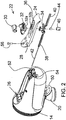
- FIG. 1 shows an underwater photography focusing light 10 of the invention.
- the focusing light device has a housing 12 including a main body or casing 14 and a front bezel 16 with a window 18 of glass, the casing, bezel and glass being sealed in watertight relationship.
- a mounting base 20 having a fitting, not shown, for attachment to an underwater camera housing.
- At the base of the device is an aluminum plate that accepts a 10-32 or 1/4-20 threaded shaft commonly used in the dive industry.
- the imaging light can be attached in a number of methods. The most common for photography uses a ball joint with a friction clamp that allows the user to position and point the light easily. The other methods employ aluminum strobe arms or flexible plastic "Loc Line" joints that can be added to position the light farther away from the housing.
- the housing also includes a slide switch 22 slidable on a slide mounting or switch cover 24.
- Indicator lights preferably light pipes that conduct a light from inside the housing, are shown at 26, preferably provided to indicate light status.
- Figure 2 shows the casing 14 without the front bezel and with the switch assembly removed.
- the casing or body 14 is water-sealed in the configuration shown, with the switch components being outside the water seal.
- the indicator light pipes 26 are positioned to extend up through holes 28 in the slide mounting or switch cover 24.
- the light pipes direct light from the single driver circuit board (discussed below) up to the proper viewing angle for the diver.
- Light pipes are typically clear acrylic, molded or extruded, straight or bent, conducting light by internal reflection.
- the switch 22 includes a switch cap 30 for finger contact and a switch base 32 that receives the cap, together referred to as a switch of the slide switch 22.
- a shuttle member 34 of the slide switch 22 connects to the switch base 32 through a slide slot 36 of the switch cover 24, and this shuttle member is biased by compression springs 38 and 40 toward a generally central rest position within the slot 36.
- the springs 38 and 40 are held in line by a spring shaft 42 and are captured within the assembly when the slide mounting 24 and the other components are in place.
- the slide switch 22 preferably has a locking feature to hold it in the rest position when desired, to avoid inadvertent switching on.
- a small nipple 32a can be seen on the bottom side of the switch base 32 in Figure 2 , and a similar nipple can be 180°-opposed.
- the slide member comprised of the components 32 and 30 can be rotated 90° relative to the switch cover 24, at which point the nipples will engage in detents 32b provided in the switch cover. This provides a lock out feature to protect against inadvertent moving of the slide switch and turning the light on when traveling, for example.
- the switch can be unlocked by again turning the manual slide member (30, 32) 90° in either direction, once again allowing the switch to move forward or back when intentionally pushed.
- the switch assembly 22 is not mechanically connected to switch the light color or power. This is effected by a magnetic coupling, to avoid the need for a dynamic water seal.
- the assembly includes a magnet 44 held within a magnet cup 46 that is secured at the bottom of the switch shuttle 34. Movement of the switch assembly including the magnet 44, by sliding the switch cap 30, is picked up by electronics within the sealed casing 14 as further discussed below.
- Figure 2 also shows a D-ring 50 preferably included adjacent to the mounting base 20, that allows the light to attach to a lanyard for non-photographic applications such as scientific dives.
- charging ports 52 and 54 for the battery preferably a lithium-ion battery contained within the casing for powering the lights.
- the charger has mating gold plated male plugs that insert into the exposed female charging ports and causing the internal battery to be charged. The two ports provide plus and minus connections. There is a third pin that insures the plug can only be inserted in a single orientation.
- a fastener e.g. a threaded bolt 56, secures the slide mount or switch cover 24 in place on the casing.
- a clip is preferably included at the rear of the switch cover to retain that end in place without a need for a fastener. Other arrangements can be used.
- FIG. 3 The exploded view of Figure 3 indicates assembly of internal components into the casing 14, and closure of the housing via the bezel 16 and window 18. Threads 58 make the connection.
- a window retaining ring 60 is shown for holding the window within the bezel, and elastomeric O-ring seals are shown at 62 and 64.
- a battery casing is shown at 66 for the rechargeable battery.
- a cable 68 carries power, after switching, to a printed circuit board or LED board 70 that carries rows of LEDs 72, 74 and 76.
- the cable 68 plugs into the back of the PCB 70.
- a PCB retainer is shown at 78.
- An LED driver printed circuit board 80 includes switching for the LEDs.
- the switching is operated by magnetic pickups 82, three of which are seen in the drawing. These are sensitive to the movement of the slide switch 22 forward and back.
- sliding the switch forward momentarily initially turns power on and selects, in sequence, low, medium and high white light power settings.
- Momentarily moving the switch back to a rear position will switch off white light and turn on red light, which preferably has only one level but could be provided with more if desired. Holding the switch to a rear position or to the forward position will switch power off.
- the red light could be on whenever power is on; the red LEDs draw less power, about 200 lumens, while the white LEDs can have a high setting at about 600 lumens.
- the red light could be provided with adjustable power level if desired.
- the rows of white LEDs in the illustrated assembly are at 72 and 76, top and bottom.
- the center row 74 is comprised of red LEDs.
- a reflector disc 84 immediately in front of the LED printed circuit board 70 has individual reflectors 86 positioned in front of each LED, with a desired angle of reflection provided as a conical annulus in each opening.
- a reflector mask is shown at 88.
- multi-color LEDs are on the PC board 70 in position to be picked up by the light pipes 26.
- multi-color LEDs these preferably indicate low, medium and high white light settings by the number of light pipes illuminated, and with different colors also indicate remaining battery charge.
- green light from the light pipes can indicate above 75% power remaining; amber can signal 50% to 75%; red can warn of 25% to 50%; and flashing red can show a critical condition of under 25% battery remaining. This is very important in underwater night photography.
- the illustrated focusing and imaging light assembly is efficient in design, is readily attached to an underwater camera casing and is very conveniently used for use of initial white focusing light, at a selected level, and for instant switching to red light for moving in on a subject.
- An underwater camera continues to auto focus the subject under red lighting, without startling the living photography subject.
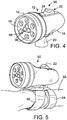
- FIG 4 shows in perspective a second embodiment of an underwater light 90 of the invention.
- this dive light can have a base 20 to enable mounting on another underwater device, or it can have a bracket to provide a wrist mounting.
- Figure 5 shows a wrist mounting, with two straps 92 and 94 to extend around the user's wrist indicated at 95. The respective straps can engage around the wrist and palm.
- the flood/spot underwater dive light 90 has exterior components similar to those of the above-described device 10: a housing 12 including a main body or casing 14 and a front bezel 16 with a window 18 preferably of glass.
- the casing, bezel and glass are in sealed watertight relationship.
- the housing assembly includes a slide switch 22 slidable on a slide mounting or switch cover 24.
- Indicator lights as in the first embodiment preferably included, as shown at 26 in Figure 1 .
- the construction of the casing 14 and the switch assembly is similar to that shown in Figure 2 and described above.
- the slide switch 22 preferably also functions in the same way as described above, although switching between different types of LED arrays.
- Figure 4 shows a ring of flood LEDs 96, which can be six in number, in an outer array within the glass window 18.
- a tight cluster of preferably three spot LEDs 98 At the center of the ring of flood LEDs is a tight cluster of preferably three spot LEDs 98.
- the slide switch 22 is used to select between flood light via the LEDs 96 and spot light via the LEDs 98, by momentarily moving the switch back to a rear position.
- Other control options using the slide switch 22 are the same as above: toggling the switch forward changes the power level, with level status being indicated by the light pipes 26 shown in Figure 2 . Holding the switch to a rear position or to the forward position will be effective to switch off power.
- the switch 22 preferably has a locking feature to hold it in the rest position when desired, to avoid inadvertent switching.
- the locking feature structure is the same as described above.
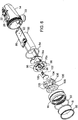
- Figure 6 is an exploded assembly drawing very similar to that of Figure 3 , but with the flood/spot LEDs and optics rather than the red/white LEDs discussed for the earlier embodiment.
- the same reference numbers are used for components that are the same as those in Figure 3 .
- the LED printed circuit board or LED board 70a is fitted into the assembly and the casing 14 in the same way as above, but the LEDs and optics are somewhat different.
- an outer ring of preferably six flood LEDs 96 are mounted on the LED board 70a, connected in series as shown, and a tight cluster of preferably three centrally located LEDs 98 are the spot LEDs, also connected in series but in a separate circuit from the flood LEDs.
- a PCB retainer is shown at 78a, behind the LED board 70a.
- the focus LEDs 98 project light that is focused by a transparent mounting plate 100 having three TIR (total internal reflection) lenses that focus the LED light to spot focus.
- the spot angle in a preferred embodiment is between about 8° and about 17°, or slightly wider.
- a pin connector seen at 102 is soldered to the front of the LED board 70a, which is a metal core board with dielectric at front, and the pins extend through to connect with the LED driver printed circuit board 80.
- a reflector 104 for the flood LEDs 96 has a center opening 106 sufficiently large to accommodate the TIR lens plate 100.
- the reflector 104 includes essentially conical reflector recesses 105, one for each flood LED.
- a sticker 108 is secured over the assembled reflector 104 and TIR device 100, for decorative purposes as seen in Figure 4 .
- the TIR lens a solid piece of clear plastic, does an effective job of focusing the beam into a tighter spread in a short space.
- the flood reflectors 105 are shallow, and the LEDs need to be placed as close to the glass as possible to get the wide beam desired - approximately 60°.
- a spot beam requires a deeper reflector or a TIR lens to gather the light emitted widely and to redirect it back center, creating a spot beam. Achieving the two types of beams from the same device is difficult - LEDs close to the glass window for flood light and LEDs far back from the window for a spot beam.
- reflectors could be used to create the spot beam, TIRs tend to be smaller for doing the equivalent focusing.
- the invention makes a compromise with a moderately shallow system design that allows enough depth for a reasonable spot beam (about 8° to 17°) while still allowing the flood to deliver close to 60°.
- the flood reflectors are "a-focal". They are designed to spread the beam and mix it to make it clean. Instead of a typical parabolic reflector the flood reflector is simply a cone that scatters the light and thereby encourages a clean mixing of the light with no focal point, producing a nice even flood. Because the flood reflector is somewhat deeper than the depth needed for the TIRs for the spot, the a-focal cones can have a step in them, with a tighter cone close to the LED, stepping wider to essentially put the cone surface farther from the LED so it does not interfere with the escaping light.
- the diving light 10 of the invention emits a flood light beam, at maximum power, of about 1200 lumens.
- the spot beam is preferably about 500 lumens.
- the weight of the unit preferably is no more than about 265 grams (0.6 pound).
- the flood beam angle is about 60°, while the spot angle preferably is in the range of about 8° to 17°.
- the unit will produce 1200 lumen flood light for about 70 minutes; 600 lumen flood light for about 140 minutes, and 300 lumen flood light for about 280 minutes. Charge time is about 150 minutes.
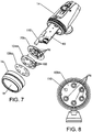
- Figure 7 shows an exploded perspective view of an embodiment of the invention that includes a lasing device.
- one of the flood LEDs 96 has been removed from the outer ring array of six LEDs on the modified LED circuit board 70b, to make room for the lasing device 110 where it will fit in the compact housing.
- the sixth LED could be moved to the center or left off if not required for the desired lumen output.
- On the modified reflector 104a one of the reflector cones 105 has been removed to make room for the lasing device.
- the modified sticker 108a one of the holes has been made smaller to mask the outer portion of the lasing device cosmetically while allowing the laser beam to pass through.
- the lasing device is mounted to the driver printed circuit board 80 so that it can be controlled easily by the switching mechanism previously described.
- the switch has a momentary (spring-biased toward off) feature for the laser, for brief periods of laser beam use.
- Figure 8 shows a front elevation view.
- the five LEDs 96 shown provide spot or flood output, as described above.
- the lasing tube 110 provides the green laser output.
- LED output colors can be used if desired. LED output colors can also be as desired.
- the ability to select blue light (whether with blue-emitting LEDs or via a filter) when filming during daylight is important because it allows the videographer to match the color of light from the video lights to the color of sunlight filtered through seawater. Blue light also is useful for capturing on film an underwater creature that phosphors and can only be seen with blue light. Infrared is useful in military applications. Any desired light wavelength can be included, by inclusion of LEDs for the light color or by filtration, which can be part of the internal optics or could be an external filter. An LED array can have mixed LEDs to achieve a desired output color.
Landscapes
- Engineering & Computer Science (AREA)
- General Engineering & Computer Science (AREA)
- Stroboscope Apparatuses (AREA)
- Arrangement Of Elements, Cooling, Sealing, Or The Like Of Lighting Devices (AREA)
- Studio Devices (AREA)
- Fastening Of Light Sources Or Lamp Holders (AREA)
- Slide Switches (AREA)
- Switch Cases, Indication, And Locking (AREA)
Claims (14)
- Lampe sous-marine (10) pour plongeurs, comprenant :une enveloppe étanche (12) qui contient une base de montage (20) pour une fixation à une enveloppe de caméra sous-marine,plusieurs LED qui sont montées dans l'enveloppe (12) pour dépasser de l'avant de celle-ci et qui comprennent des LED à faisceau large (96) et des LED à faisceau étroit (98),un circuit de commande dans l'enveloppe (12) pour les LED à faisceau large (96) et les LED à faisceau étroit (98), qui est conçu pour commander les LED à faisceau large (96) et les LED à faisceau étroit (98) séparément,un système optique qui est placé devant les LED afin de diriger la lumière provenant des LED à faisceau large (96) sous la forme d'une lumière à faisceau large, et de diriger la lumière provenant des LED à faisceau étroit (98) sous la forme d'une lumière à faisceau étroit,une fenêtre (18) à l'avant de l'enveloppe, à travers laquelle la lumière à faisceau large ou étroit (98) qui est sélectionnée peut être projetée vers l'avant,un dispositif laser (110) qui est monté dans l'enveloppe pour projeter un faisceau de pointage laser visible à travers la fenêtre (18) à l'avant de l'enveloppe, le faisceau de pointage laser ayant une couleur de sortie de laser verte ou autre, et étant apte à indiquer aux plongeurs des objets spécifiques,une source d'alimentation, etun commutateur (22) sur l'extérieur de l'enveloppe, qui est monté de manière fonctionnelle pour la mise sous tension, à partir de la source d'alimentation, du dispositif laser ou des LED afin de mettre sous tension sélectivement le dispositif laser, les LED à faisceau large (96) et les LED à faisceau étroit (98),le commutateur ayant une fonction momentanée pour de courtes périodes d'utilisation de faisceau de pointage laser.
- Lampe sous-marine (10) de la revendication 1, dans laquelle le système optique présente une série de trous coniques de réflecteur (86) qui sont placés de manière à se trouver devant les LED et sur la trajectoire de la lumière provenant de celles-ci.
- Lampe sous-marine (10) de la revendication 2, comprenant également des voyants lumineux (26), sur l'extérieur de l'enveloppe, qui indiquent le niveau de puissance de la lumière blanche.
- Lampe sous-marine (10) de la revendication 1, dans laquelle l'enveloppe comprend un boîtier (14) et un couvercle avant avec une lunette (16) qui retient une fenêtre (18), la lunette (16) présentant des filets de vis pour être fixée au boîtier (14) à l'aide de filets prévus sur ledit boîtier (14).
- Lampe sous-marine (10) de la revendication 1, dans laquelle les LEDS à faisceau large (96) sont placées dans un réseau annulaire à l'avant de l'enveloppe, et les LEDS à faisceau étroit (98) sont placées en un ensemble central très groupé, au centre de l'alignement annulaire.
- Lampe sous-marine (10) de la revendication 1, dans laquelle les LED à faisceau large (96) ont un système optique qui produit un angle de divergence d'environ 60°.
- Lampe sous-marine (10) de la revendication 1, dans laquelle les LED à faisceau étroit (98) ont un système optique qui produit un angle de divergence d'environ 8°.
- Lampe sous-marine (10) de la revendication 1, dans laquelle le commutateur (22) comprend un commutateur coulissant (22) avec un élément coulissant extérieur à commande manuelle qui est placé sur l'extérieur de l'enveloppe en vue d'un mouvement coulissant sur un couvercle de commutateur (24), l'élément coulissant (22) étant contraint par ressort vers une position de repos, et l'enveloppe étant étanche, dessous et indépendamment de l'élément coulissant et du couvercle de commutateur (24), avec un aimant (44) relié à l'élément coulissant, et le commutateur (22) contenant, dans un espace étanche interne de l'enveloppe, des capteurs magnétiques dans le circuit, pour détecter le mouvement de l'aimant (44) et effectuer la mise sous tension, la mise hors tension et les sélections entre la lumière à faisceau large et la lumière à faisceau étroit.
- Lampe sous-marine (10) de la revendication 8, contenant dans l'enveloppe un circuit imprimé (70a) avec des drivers de LED et les capteurs magnétiques.
- Lampe sous-marine (10) de la revendication 8, dans laquelle le commutateur coulissant (22) comporte un dispositif de verrouillage qui est enclenché grâce à une rotation de 90° de l'élément coulissant à commande manuelle, quand il est en position de repos, le dispositif de verrouillage agissant pour empêcher une mise sous tension involontaire de la lampe sous-marine.
- Lampe sous-marine (10) de la revendication 1, dans laquelle la lumière à faisceau large ou la lumière à faisceau étroit est une lumière bleue.
- Lampe sous-marine (10) de la revendication 9, contenant un circuit imprimé de LED (70) avec les LED, le circuit imprimé de LED (70) étant ouvert pour le passage d'un rayon laser à partir du dispositif laser, qui est monté derrière le circuit imprimé de LED (70).
- Lampe sous-marine (10) de la revendication 1, dans laquelle les LED à faisceau large (96) et les LED à faisceau étroit (98) sont toutes les deux montées sur un seul circuit imprimé de LED (70a).
- Lampe sous-marine (10) de la revendication 13, dans laquelle les LED à faisceau étroit sont focalisées par une plaque de montage transparente (100) qui comporte trois lentilles à réflexion totale interne.
Applications Claiming Priority (2)
| Application Number | Priority Date | Filing Date | Title |
|---|---|---|---|
| US12/927,608 US9188292B2 (en) | 2010-11-17 | 2010-11-17 | Diver's underwater light for selecting between two types of light |
| PCT/US2011/001921 WO2012067657A1 (fr) | 2010-11-17 | 2011-11-17 | Lampes sous-marines pour plongeurs |
Publications (3)
| Publication Number | Publication Date |
|---|---|
| EP2641013A1 EP2641013A1 (fr) | 2013-09-25 |
| EP2641013A4 EP2641013A4 (fr) | 2014-07-09 |
| EP2641013B1 true EP2641013B1 (fr) | 2019-01-09 |
Family
ID=46047602
Family Applications (1)
| Application Number | Title | Priority Date | Filing Date |
|---|---|---|---|
| EP11840945.7A Active EP2641013B1 (fr) | 2010-11-17 | 2011-11-17 | Lampes sous-marines pour plongeurs |
Country Status (4)
| Country | Link |
|---|---|
| US (1) | US9188292B2 (fr) |
| EP (1) | EP2641013B1 (fr) |
| JP (1) | JP2014503840A (fr) |
| WO (1) | WO2012067657A1 (fr) |
Families Citing this family (35)
| Publication number | Priority date | Publication date | Assignee | Title |
|---|---|---|---|---|
| US9863622B1 (en) | 2010-11-17 | 2018-01-09 | Light & Motion Industries | Underwater lights for divers |
| US9028112B2 (en) | 2011-01-03 | 2015-05-12 | Nite Ize, Inc. | Personal lighting device |
| CN103403446B (zh) * | 2011-01-03 | 2016-02-17 | 力特亿泽公司 | 个人照明装置以及操作照明装置的方法 |
| GB2498528B (en) * | 2012-01-17 | 2018-05-30 | Hartley Richard | Multifunctional light |
| GB201220965D0 (en) * | 2012-11-21 | 2013-01-02 | Smidsy Ltd | Light-projecting devices |
| WO2014138389A1 (fr) * | 2013-03-06 | 2014-09-12 | International Development LLC | Dispositif d'éclairage compact |
| US9030606B2 (en) * | 2013-03-14 | 2015-05-12 | Gopro, Inc. | Wireless camera housing illuminators |
| US9822962B2 (en) | 2014-02-28 | 2017-11-21 | Bryan C. McGilvray | Underwater modular light probe |
| EP2947371A1 (fr) | 2014-05-22 | 2015-11-25 | Leys | Éclairage portable |
| CN103994337A (zh) * | 2014-05-27 | 2014-08-20 | 西安精英光电技术有限公司 | 一种带激光指示器的led强光手电筒 |
| US9625127B2 (en) * | 2014-05-31 | 2017-04-18 | Industralight, Llc | Rugged lighting system |
| FR3031567A1 (fr) * | 2015-01-08 | 2016-07-15 | Francis Beckers | Dispositif d'eclairage portatif pour plongeur ou spationaute |
| FR3031496A1 (fr) * | 2015-01-08 | 2016-07-15 | Francis Beckers | Equipement individuel de plongee multifonctions |
| HK1208303A2 (en) * | 2015-10-27 | 2016-02-26 | 潛點有限公司 | An underwater photographic lighting device |
| CN105810070A (zh) * | 2016-05-20 | 2016-07-27 | 于天舒 | 一种高中物理波动光学演示仪 |
| US10054287B2 (en) | 2016-05-25 | 2018-08-21 | Arctic Rays, Llc | High intensity marine LED strobe and torch light |
| US10235860B2 (en) | 2016-08-26 | 2019-03-19 | Irene Skidmore | Location beacon assembly |
| DE102016012794B4 (de) | 2016-10-26 | 2022-02-24 | Olaf Rautner | Set aus einheitlichen, passiven Taucher-Markierungsleuchten |
| US10113735B2 (en) * | 2017-02-08 | 2018-10-30 | Light & Motion Industries | Modular LED lighting device with different interchangeable LED heads |
| WO2018148695A1 (fr) | 2017-02-12 | 2018-08-16 | Deepsea Power & Light Llc | Luminaires subaquatiques avec hublots comprenant des entités de lentilles pour fournir des faisceaux de sortie sur mesure |
| CN108006507A (zh) * | 2017-12-11 | 2018-05-08 | 广东羿斐信息科技有限公司 | 一种带有监视功能的水底灯 |
| CN210004181U (zh) | 2018-04-26 | 2020-01-31 | 米沃奇电动工具公司 | 便携式灯 |
| USD906559S1 (en) | 2018-04-26 | 2020-12-29 | Milwaukee Electric Tool Corporation | Light |
| US20200088369A1 (en) * | 2018-09-13 | 2020-03-19 | Koehler-Bright Star LLC | Electronically variable light beam pattern for lighting device |
| UA118644C2 (uk) * | 2018-09-25 | 2019-02-11 | Василь Олександрович Руських | Портативний переносний освітлювальний пристрій для підводної фото- та відеозйомки |
| DE102019104999A1 (de) * | 2019-02-27 | 2020-08-27 | Brehmer Gmbh & Co. Kg | Scheinwerfer, insbesondere Kraftfahrzeugscheinwerfer |
| KR102274071B1 (ko) * | 2019-04-10 | 2021-07-08 | 주식회사 에이스프로토 | 수중촬영장치 |
| CN110985903B (zh) | 2019-12-31 | 2020-08-14 | 江苏舒适照明有限公司 | 一种灯模组 |
| US11598517B2 (en) | 2019-12-31 | 2023-03-07 | Lumien Enterprise, Inc. | Electronic module group |
| US11674676B2 (en) | 2020-01-10 | 2023-06-13 | Streamlight, Inc. | Battery assembly for a hand holdable light |
| US11192494B2 (en) | 2020-02-07 | 2021-12-07 | Honeywell International Inc. | Systems and methods for search and landing light |
| CN111503556B (zh) * | 2020-04-23 | 2020-11-27 | 江苏舒适照明有限公司 | 一种射灯结构 |
| CN113485057B (zh) * | 2021-06-04 | 2022-06-07 | 浙江大华技术股份有限公司 | 补光灯组件及补光设备 |
| CN113296331B (zh) * | 2021-07-27 | 2021-10-15 | 深圳市正光影像器材有限公司 | 一种led自动化电动调焦摄影聚光灯及其方法 |
| KR102624851B1 (ko) * | 2021-12-17 | 2024-01-16 | 주식회사 해양기술이앤지 | 수중 영상 촬영 장치 |
Citations (2)
| Publication number | Priority date | Publication date | Assignee | Title |
|---|---|---|---|---|
| US5359779A (en) * | 1992-10-08 | 1994-11-01 | Polk Richard N | Illumination and laser sighting device for a weapon |
| US20020001463A1 (en) * | 2000-02-18 | 2002-01-03 | Akihide Inoue | Flash lamps for underwater photography provided with target light and control methods and devices therefor |
Family Cites Families (26)
| Publication number | Priority date | Publication date | Assignee | Title |
|---|---|---|---|---|
| US3792389A (en) * | 1971-12-22 | 1974-02-12 | J Murphy | Flashlight and switch assembly |
| US3794825A (en) * | 1972-05-05 | 1974-02-26 | C Krupansky | Waterproof flashlight |
| JPH0562928U (ja) * | 1992-01-31 | 1993-08-20 | 日本開閉器工業株式会社 | ロック機構付きスライドスイッチ |
| JP3002131U (ja) * | 1994-03-18 | 1994-09-20 | 有限会社鉄道用品商会 | 携帯用電灯 |
| US6095661A (en) * | 1998-03-19 | 2000-08-01 | Ppt Vision, Inc. | Method and apparatus for an L.E.D. flashlight |
| US6702452B2 (en) * | 1999-11-15 | 2004-03-09 | Xenonics, Inc. | Apparatus and method for operating a portable xenon arc searchlight |
| JP2001228517A (ja) * | 2000-02-18 | 2001-08-24 | Inon:Kk | レーザダイオードのターゲットライト付き水中撮影用ストロボ |
| CA2407255A1 (fr) * | 2000-07-03 | 2002-10-22 | Harald Opolka | Lampe, en particulier lampe de salon, de bureau ou de poche |
| US6483651B1 (en) * | 2001-05-09 | 2002-11-19 | Scott D. Maurer | Lighted magnifying device incorporating a light emitting diode |
| JP2003178602A (ja) * | 2001-12-10 | 2003-06-27 | Koito Mfg Co Ltd | 照明装置 |
| AU2003901553A0 (en) * | 2003-04-03 | 2003-05-01 | Eveready Battery Company, Inc | Waterproof rechargeable flashlight |
| US20050002186A1 (en) * | 2003-07-01 | 2005-01-06 | Vector Products, Inc. | Multi-beam flashlight |
| US20050036306A1 (en) | 2003-07-30 | 2005-02-17 | Chih-Ching Hsien | Flashlight having a power indication function |
| JP2005338280A (ja) * | 2004-05-25 | 2005-12-08 | Nikon Corp | 撮影用照明装置およびカメラ |
| US20050281020A1 (en) * | 2004-06-16 | 2005-12-22 | Liaw Suh J | Battery charger for water-resistant flashlight |
| US7199316B2 (en) * | 2004-09-10 | 2007-04-03 | W.T. Storey, Inc. | Multifunction switch for operating a device in a sealed container |
| US7434955B2 (en) * | 2004-10-13 | 2008-10-14 | Premierlight Limited | Flashlight system |
| US7303303B1 (en) | 2005-03-28 | 2007-12-04 | Derek Haynes | Lip light |
| JP3112736U (ja) * | 2005-05-23 | 2005-08-25 | 伸和エンジニヤリング株式会社 | 合図灯 |
| US20070279900A1 (en) | 2005-11-01 | 2007-12-06 | Nexxus Lighting, Inc. | Submersible LED Light Fixture System |
| US20070115387A1 (en) | 2005-11-21 | 2007-05-24 | Ho Kenneth K | Underwater camera combination |
| CN101389895A (zh) | 2006-02-20 | 2009-03-18 | 皇家飞利浦电子股份有限公司 | 便携式照明器件 |
| US7771077B2 (en) * | 2006-05-03 | 2010-08-10 | Miller Rodney H | Mechanism and cap for an electrically powered device, electrically powered device and lighting device with such a cap |
| KR20100074150A (ko) | 2007-08-22 | 2010-07-01 | 퀀텀 리프 리서치 인코포레이티드 | 편차 및 고도 조절 기구를 가진 복수의 광원을 포함하는 조명 조립체 |
| JP4569683B2 (ja) * | 2007-10-16 | 2010-10-27 | 東芝ライテック株式会社 | 発光素子ランプ及び照明器具 |
| US7888883B2 (en) | 2008-01-25 | 2011-02-15 | Eveready Battery Company, Inc. | Lighting device having cross-fade and method thereof |
-
2010
- 2010-11-17 US US12/927,608 patent/US9188292B2/en active Active
-
2011
- 2011-11-17 WO PCT/US2011/001921 patent/WO2012067657A1/fr active Application Filing
- 2011-11-17 JP JP2013539817A patent/JP2014503840A/ja active Pending
- 2011-11-17 EP EP11840945.7A patent/EP2641013B1/fr active Active
Patent Citations (2)
| Publication number | Priority date | Publication date | Assignee | Title |
|---|---|---|---|---|
| US5359779A (en) * | 1992-10-08 | 1994-11-01 | Polk Richard N | Illumination and laser sighting device for a weapon |
| US20020001463A1 (en) * | 2000-02-18 | 2002-01-03 | Akihide Inoue | Flash lamps for underwater photography provided with target light and control methods and devices therefor |
Also Published As
| Publication number | Publication date |
|---|---|
| US20120120639A1 (en) | 2012-05-17 |
| US9188292B2 (en) | 2015-11-17 |
| EP2641013A1 (fr) | 2013-09-25 |
| JP2014503840A (ja) | 2014-02-13 |
| EP2641013A4 (fr) | 2014-07-09 |
| WO2012067657A1 (fr) | 2012-05-24 |
Similar Documents
| Publication | Publication Date | Title |
|---|---|---|
| EP2641013B1 (fr) | Lampes sous-marines pour plongeurs | |
| US9863622B1 (en) | Underwater lights for divers | |
| EP2641011B1 (fr) | Lampe réglable pour la photographie sous-marine | |
| US9746170B1 (en) | Adjustable light for underwater photography | |
| US10344924B1 (en) | Multibeam lighting system | |
| US7226178B2 (en) | Lamp for an underwater camera | |
| US11988343B2 (en) | Rugged all purpose lighting cube | |
| US20160209025A1 (en) | Lighting device attachment for mobile devices | |
| US9512969B1 (en) | Modular LED lamp fixtures and associated accessories | |
| US9618827B2 (en) | Illumination device for performing videography and photography with mobile devices | |
| JP4183307B2 (ja) | 水中カメラハウジング | |
| JP3850973B2 (ja) | 主灯・増灯両用型の光感応ストロボ及び水中カメラと の光接続システム | |
| JPH09218442A (ja) | ターゲットライトを装備した水中リングライト | |
| CN209605812U (zh) | 一种基于混合光源的水下环境观测系统 | |
| CN109974666A (zh) | 一种基于混合光源的水下环境观测系统 | |
| KR101821959B1 (ko) | 레저용 조명기 | |
| RU71009U1 (ru) | Бокс камеры для подводной съемки | |
| US20160209001A1 (en) | Reflective non-paraboloidal beam-shaping optics | |
| CN207298478U (zh) | 多媒体手电 | |
| JP2001228517A (ja) | レーザダイオードのターゲットライト付き水中撮影用ストロボ | |
| JP2000056378A (ja) | 多機能ファインダー付き防水カメラハウジング | |
| US20190053478A1 (en) | Fishing pole with led flashlight integrated in handle | |
| JP2006292794A (ja) | カメラの照明システム | |
| JPH10170992A (ja) | 撮影被写体の的確認装置 | |
| JPS58100841A (ja) | ストロボ内蔵水陸兼用カメラ |
Legal Events
| Date | Code | Title | Description |
|---|---|---|---|
| PUAI | Public reference made under article 153(3) epc to a published international application that has entered the european phase |
Free format text: ORIGINAL CODE: 0009012 |
|
| TPAC | Observations filed by third parties |
Free format text: ORIGINAL CODE: EPIDOSNTIPA |
|
| 17P | Request for examination filed |
Effective date: 20130523 |
|
| AK | Designated contracting states |
Kind code of ref document: A1 Designated state(s): AL AT BE BG CH CY CZ DE DK EE ES FI FR GB GR HR HU IE IS IT LI LT LU LV MC MK MT NL NO PL PT RO RS SE SI SK SM TR |
|
| DAX | Request for extension of the european patent (deleted) | ||
| RAP1 | Party data changed (applicant data changed or rights of an application transferred) |
Owner name: LIGHT & MOTION INDUSTRIES |
|
| A4 | Supplementary search report drawn up and despatched |
Effective date: 20140611 |
|
| RIC1 | Information provided on ipc code assigned before grant |
Ipc: F21S 4/00 20060101AFI20140605BHEP Ipc: F21L 4/00 20060101ALI20140605BHEP |
|
| 17Q | First examination report despatched |
Effective date: 20150709 |
|
| STAA | Information on the status of an ep patent application or granted ep patent |
Free format text: STATUS: EXAMINATION IS IN PROGRESS |
|
| GRAP | Despatch of communication of intention to grant a patent |
Free format text: ORIGINAL CODE: EPIDOSNIGR1 |
|
| STAA | Information on the status of an ep patent application or granted ep patent |
Free format text: STATUS: GRANT OF PATENT IS INTENDED |
|
| INTG | Intention to grant announced |
Effective date: 20180620 |
|
| GRAS | Grant fee paid |
Free format text: ORIGINAL CODE: EPIDOSNIGR3 |
|
| GRAJ | Information related to disapproval of communication of intention to grant by the applicant or resumption of examination proceedings by the epo deleted |
Free format text: ORIGINAL CODE: EPIDOSDIGR1 |
|
| GRAL | Information related to payment of fee for publishing/printing deleted |
Free format text: ORIGINAL CODE: EPIDOSDIGR3 |
|
| STAA | Information on the status of an ep patent application or granted ep patent |
Free format text: STATUS: EXAMINATION IS IN PROGRESS |
|
| GRAP | Despatch of communication of intention to grant a patent |
Free format text: ORIGINAL CODE: EPIDOSNIGR1 |
|
| STAA | Information on the status of an ep patent application or granted ep patent |
Free format text: STATUS: GRANT OF PATENT IS INTENDED |
|
| INTC | Intention to grant announced (deleted) | ||
| GRAA | (expected) grant |
Free format text: ORIGINAL CODE: 0009210 |
|
| STAA | Information on the status of an ep patent application or granted ep patent |
Free format text: STATUS: THE PATENT HAS BEEN GRANTED |
|
| INTG | Intention to grant announced |
Effective date: 20181114 |
|
| AK | Designated contracting states |
Kind code of ref document: B1 Designated state(s): AL AT BE BG CH CY CZ DE DK EE ES FI FR GB GR HR HU IE IS IT LI LT LU LV MC MK MT NL NO PL PT RO RS SE SI SK SM TR |
|
| REG | Reference to a national code |
Ref country code: GB Ref legal event code: FG4D |
|
| REG | Reference to a national code |
Ref country code: CH Ref legal event code: EP Ref country code: AT Ref legal event code: REF Ref document number: 1087756 Country of ref document: AT Kind code of ref document: T Effective date: 20190115 |
|
| REG | Reference to a national code |
Ref country code: DE Ref legal event code: R096 Ref document number: 602011055658 Country of ref document: DE |
|
| REG | Reference to a national code |
Ref country code: IE Ref legal event code: FG4D |
|
| REG | Reference to a national code |
Ref country code: NL Ref legal event code: MP Effective date: 20190109 |
|
| REG | Reference to a national code |
Ref country code: LT Ref legal event code: MG4D |
|
| PG25 | Lapsed in a contracting state [announced via postgrant information from national office to epo] |
Ref country code: NL Free format text: LAPSE BECAUSE OF FAILURE TO SUBMIT A TRANSLATION OF THE DESCRIPTION OR TO PAY THE FEE WITHIN THE PRESCRIBED TIME-LIMIT Effective date: 20190109 |
|
| REG | Reference to a national code |
Ref country code: AT Ref legal event code: MK05 Ref document number: 1087756 Country of ref document: AT Kind code of ref document: T Effective date: 20190109 |
|
| PG25 | Lapsed in a contracting state [announced via postgrant information from national office to epo] |
Ref country code: PT Free format text: LAPSE BECAUSE OF FAILURE TO SUBMIT A TRANSLATION OF THE DESCRIPTION OR TO PAY THE FEE WITHIN THE PRESCRIBED TIME-LIMIT Effective date: 20190509 Ref country code: ES Free format text: LAPSE BECAUSE OF FAILURE TO SUBMIT A TRANSLATION OF THE DESCRIPTION OR TO PAY THE FEE WITHIN THE PRESCRIBED TIME-LIMIT Effective date: 20190109 Ref country code: LT Free format text: LAPSE BECAUSE OF FAILURE TO SUBMIT A TRANSLATION OF THE DESCRIPTION OR TO PAY THE FEE WITHIN THE PRESCRIBED TIME-LIMIT Effective date: 20190109 Ref country code: NO Free format text: LAPSE BECAUSE OF FAILURE TO SUBMIT A TRANSLATION OF THE DESCRIPTION OR TO PAY THE FEE WITHIN THE PRESCRIBED TIME-LIMIT Effective date: 20190409 Ref country code: PL Free format text: LAPSE BECAUSE OF FAILURE TO SUBMIT A TRANSLATION OF THE DESCRIPTION OR TO PAY THE FEE WITHIN THE PRESCRIBED TIME-LIMIT Effective date: 20190109 Ref country code: SE Free format text: LAPSE BECAUSE OF FAILURE TO SUBMIT A TRANSLATION OF THE DESCRIPTION OR TO PAY THE FEE WITHIN THE PRESCRIBED TIME-LIMIT Effective date: 20190109 Ref country code: FI Free format text: LAPSE BECAUSE OF FAILURE TO SUBMIT A TRANSLATION OF THE DESCRIPTION OR TO PAY THE FEE WITHIN THE PRESCRIBED TIME-LIMIT Effective date: 20190109 |
|
| PG25 | Lapsed in a contracting state [announced via postgrant information from national office to epo] |
Ref country code: BG Free format text: LAPSE BECAUSE OF FAILURE TO SUBMIT A TRANSLATION OF THE DESCRIPTION OR TO PAY THE FEE WITHIN THE PRESCRIBED TIME-LIMIT Effective date: 20190409 Ref country code: IS Free format text: LAPSE BECAUSE OF FAILURE TO SUBMIT A TRANSLATION OF THE DESCRIPTION OR TO PAY THE FEE WITHIN THE PRESCRIBED TIME-LIMIT Effective date: 20190509 Ref country code: RS Free format text: LAPSE BECAUSE OF FAILURE TO SUBMIT A TRANSLATION OF THE DESCRIPTION OR TO PAY THE FEE WITHIN THE PRESCRIBED TIME-LIMIT Effective date: 20190109 Ref country code: GR Free format text: LAPSE BECAUSE OF FAILURE TO SUBMIT A TRANSLATION OF THE DESCRIPTION OR TO PAY THE FEE WITHIN THE PRESCRIBED TIME-LIMIT Effective date: 20190410 Ref country code: LV Free format text: LAPSE BECAUSE OF FAILURE TO SUBMIT A TRANSLATION OF THE DESCRIPTION OR TO PAY THE FEE WITHIN THE PRESCRIBED TIME-LIMIT Effective date: 20190109 Ref country code: HR Free format text: LAPSE BECAUSE OF FAILURE TO SUBMIT A TRANSLATION OF THE DESCRIPTION OR TO PAY THE FEE WITHIN THE PRESCRIBED TIME-LIMIT Effective date: 20190109 |
|
| REG | Reference to a national code |
Ref country code: DE Ref legal event code: R097 Ref document number: 602011055658 Country of ref document: DE |
|
| PG25 | Lapsed in a contracting state [announced via postgrant information from national office to epo] |
Ref country code: RO Free format text: LAPSE BECAUSE OF FAILURE TO SUBMIT A TRANSLATION OF THE DESCRIPTION OR TO PAY THE FEE WITHIN THE PRESCRIBED TIME-LIMIT Effective date: 20190109 Ref country code: IT Free format text: LAPSE BECAUSE OF FAILURE TO SUBMIT A TRANSLATION OF THE DESCRIPTION OR TO PAY THE FEE WITHIN THE PRESCRIBED TIME-LIMIT Effective date: 20190109 Ref country code: SK Free format text: LAPSE BECAUSE OF FAILURE TO SUBMIT A TRANSLATION OF THE DESCRIPTION OR TO PAY THE FEE WITHIN THE PRESCRIBED TIME-LIMIT Effective date: 20190109 Ref country code: CZ Free format text: LAPSE BECAUSE OF FAILURE TO SUBMIT A TRANSLATION OF THE DESCRIPTION OR TO PAY THE FEE WITHIN THE PRESCRIBED TIME-LIMIT Effective date: 20190109 Ref country code: AL Free format text: LAPSE BECAUSE OF FAILURE TO SUBMIT A TRANSLATION OF THE DESCRIPTION OR TO PAY THE FEE WITHIN THE PRESCRIBED TIME-LIMIT Effective date: 20190109 Ref country code: AT Free format text: LAPSE BECAUSE OF FAILURE TO SUBMIT A TRANSLATION OF THE DESCRIPTION OR TO PAY THE FEE WITHIN THE PRESCRIBED TIME-LIMIT Effective date: 20190109 Ref country code: DK Free format text: LAPSE BECAUSE OF FAILURE TO SUBMIT A TRANSLATION OF THE DESCRIPTION OR TO PAY THE FEE WITHIN THE PRESCRIBED TIME-LIMIT Effective date: 20190109 Ref country code: EE Free format text: LAPSE BECAUSE OF FAILURE TO SUBMIT A TRANSLATION OF THE DESCRIPTION OR TO PAY THE FEE WITHIN THE PRESCRIBED TIME-LIMIT Effective date: 20190109 |
|
| PLBE | No opposition filed within time limit |
Free format text: ORIGINAL CODE: 0009261 |
|
| STAA | Information on the status of an ep patent application or granted ep patent |
Free format text: STATUS: NO OPPOSITION FILED WITHIN TIME LIMIT |
|
| PG25 | Lapsed in a contracting state [announced via postgrant information from national office to epo] |
Ref country code: SM Free format text: LAPSE BECAUSE OF FAILURE TO SUBMIT A TRANSLATION OF THE DESCRIPTION OR TO PAY THE FEE WITHIN THE PRESCRIBED TIME-LIMIT Effective date: 20190109 |
|
| 26N | No opposition filed |
Effective date: 20191010 |
|
| PG25 | Lapsed in a contracting state [announced via postgrant information from national office to epo] |
Ref country code: SI Free format text: LAPSE BECAUSE OF FAILURE TO SUBMIT A TRANSLATION OF THE DESCRIPTION OR TO PAY THE FEE WITHIN THE PRESCRIBED TIME-LIMIT Effective date: 20190109 |
|
| PG25 | Lapsed in a contracting state [announced via postgrant information from national office to epo] |
Ref country code: TR Free format text: LAPSE BECAUSE OF FAILURE TO SUBMIT A TRANSLATION OF THE DESCRIPTION OR TO PAY THE FEE WITHIN THE PRESCRIBED TIME-LIMIT Effective date: 20190109 |
|
| REG | Reference to a national code |
Ref country code: CH Ref legal event code: PL |
|
| PG25 | Lapsed in a contracting state [announced via postgrant information from national office to epo] |
Ref country code: LI Free format text: LAPSE BECAUSE OF NON-PAYMENT OF DUE FEES Effective date: 20191130 Ref country code: MC Free format text: LAPSE BECAUSE OF FAILURE TO SUBMIT A TRANSLATION OF THE DESCRIPTION OR TO PAY THE FEE WITHIN THE PRESCRIBED TIME-LIMIT Effective date: 20190109 Ref country code: CH Free format text: LAPSE BECAUSE OF NON-PAYMENT OF DUE FEES Effective date: 20191130 Ref country code: LU Free format text: LAPSE BECAUSE OF NON-PAYMENT OF DUE FEES Effective date: 20191117 |
|
| REG | Reference to a national code |
Ref country code: BE Ref legal event code: MM Effective date: 20191130 |
|
| GBPC | Gb: european patent ceased through non-payment of renewal fee |
Effective date: 20191117 |
|
| PG25 | Lapsed in a contracting state [announced via postgrant information from national office to epo] |
Ref country code: IE Free format text: LAPSE BECAUSE OF NON-PAYMENT OF DUE FEES Effective date: 20191117 Ref country code: GB Free format text: LAPSE BECAUSE OF NON-PAYMENT OF DUE FEES Effective date: 20191117 |
|
| PG25 | Lapsed in a contracting state [announced via postgrant information from national office to epo] |
Ref country code: BE Free format text: LAPSE BECAUSE OF NON-PAYMENT OF DUE FEES Effective date: 20191130 |
|
| PG25 | Lapsed in a contracting state [announced via postgrant information from national office to epo] |
Ref country code: CY Free format text: LAPSE BECAUSE OF FAILURE TO SUBMIT A TRANSLATION OF THE DESCRIPTION OR TO PAY THE FEE WITHIN THE PRESCRIBED TIME-LIMIT Effective date: 20190109 |
|
| PG25 | Lapsed in a contracting state [announced via postgrant information from national office to epo] |
Ref country code: MT Free format text: LAPSE BECAUSE OF FAILURE TO SUBMIT A TRANSLATION OF THE DESCRIPTION OR TO PAY THE FEE WITHIN THE PRESCRIBED TIME-LIMIT Effective date: 20190109 Ref country code: HU Free format text: LAPSE BECAUSE OF FAILURE TO SUBMIT A TRANSLATION OF THE DESCRIPTION OR TO PAY THE FEE WITHIN THE PRESCRIBED TIME-LIMIT; INVALID AB INITIO Effective date: 20111117 Ref country code: FR Free format text: LAPSE BECAUSE OF NON-PAYMENT OF DUE FEES Effective date: 20191202 |
|
| PG25 | Lapsed in a contracting state [announced via postgrant information from national office to epo] |
Ref country code: MK Free format text: LAPSE BECAUSE OF FAILURE TO SUBMIT A TRANSLATION OF THE DESCRIPTION OR TO PAY THE FEE WITHIN THE PRESCRIBED TIME-LIMIT Effective date: 20190109 |
|
| PGFP | Annual fee paid to national office [announced via postgrant information from national office to epo] |
Ref country code: DE Payment date: 20231129 Year of fee payment: 13 |