EP2640539B1 - Cutting tool and insert holder for tangential cutting insert - Google Patents
Cutting tool and insert holder for tangential cutting insert Download PDFInfo
- Publication number
- EP2640539B1 EP2640539B1 EP11784791.3A EP11784791A EP2640539B1 EP 2640539 B1 EP2640539 B1 EP 2640539B1 EP 11784791 A EP11784791 A EP 11784791A EP 2640539 B1 EP2640539 B1 EP 2640539B1
- Authority
- EP
- European Patent Office
- Prior art keywords
- insert
- base abutment
- base
- holder
- protuberance
- Prior art date
- Legal status (The legal status is an assumption and is not a legal conclusion. Google has not performed a legal analysis and makes no representation as to the accuracy of the status listed.)
- Active
Links
- 230000002093 peripheral effect Effects 0.000 claims description 6
- 230000000717 retained effect Effects 0.000 claims description 4
- 230000004075 alteration Effects 0.000 description 1
- 238000004519 manufacturing process Methods 0.000 description 1
- 230000004048 modification Effects 0.000 description 1
- 238000012986 modification Methods 0.000 description 1
- 238000005245 sintering Methods 0.000 description 1
Images


Classifications
-
- B—PERFORMING OPERATIONS; TRANSPORTING
- B23—MACHINE TOOLS; METAL-WORKING NOT OTHERWISE PROVIDED FOR
- B23B—TURNING; BORING
- B23B27/00—Tools for turning or boring machines; Tools of a similar kind in general; Accessories therefor
- B23B27/14—Cutting tools of which the bits or tips or cutting inserts are of special material
- B23B27/16—Cutting tools of which the bits or tips or cutting inserts are of special material with exchangeable cutting bits or cutting inserts, e.g. able to be clamped
- B23B27/1614—Cutting tools of which the bits or tips or cutting inserts are of special material with exchangeable cutting bits or cutting inserts, e.g. able to be clamped with plate-like cutting inserts of special shape clamped against the walls of the recess in the shank by a clamping member acting upon the wall of a hole in the insert
- B23B27/1622—Cutting tools of which the bits or tips or cutting inserts are of special material with exchangeable cutting bits or cutting inserts, e.g. able to be clamped with plate-like cutting inserts of special shape clamped against the walls of the recess in the shank by a clamping member acting upon the wall of a hole in the insert characterised by having a special shape
-
- B—PERFORMING OPERATIONS; TRANSPORTING
- B23—MACHINE TOOLS; METAL-WORKING NOT OTHERWISE PROVIDED FOR
- B23B—TURNING; BORING
- B23B27/00—Tools for turning or boring machines; Tools of a similar kind in general; Accessories therefor
- B23B27/14—Cutting tools of which the bits or tips or cutting inserts are of special material
- B23B27/16—Cutting tools of which the bits or tips or cutting inserts are of special material with exchangeable cutting bits or cutting inserts, e.g. able to be clamped
-
- B—PERFORMING OPERATIONS; TRANSPORTING
- B23—MACHINE TOOLS; METAL-WORKING NOT OTHERWISE PROVIDED FOR
- B23B—TURNING; BORING
- B23B29/00—Holders for non-rotary cutting tools; Boring bars or boring heads; Accessories for tool holders
- B23B29/04—Tool holders for a single cutting tool
-
- B—PERFORMING OPERATIONS; TRANSPORTING
- B23—MACHINE TOOLS; METAL-WORKING NOT OTHERWISE PROVIDED FOR
- B23B—TURNING; BORING
- B23B2200/00—Details of cutting inserts
- B23B2200/08—Rake or top surfaces
- B23B2200/081—Rake or top surfaces with projections
-
- B—PERFORMING OPERATIONS; TRANSPORTING
- B23—MACHINE TOOLS; METAL-WORKING NOT OTHERWISE PROVIDED FOR
- B23B—TURNING; BORING
- B23B2200/00—Details of cutting inserts
- B23B2200/16—Supporting or bottom surfaces
- B23B2200/161—Supporting or bottom surfaces with projections
-
- B—PERFORMING OPERATIONS; TRANSPORTING
- B23—MACHINE TOOLS; METAL-WORKING NOT OTHERWISE PROVIDED FOR
- B23B—TURNING; BORING
- B23B2200/00—Details of cutting inserts
- B23B2200/16—Supporting or bottom surfaces
- B23B2200/163—Supporting or bottom surfaces discontinuous
-
- B—PERFORMING OPERATIONS; TRANSPORTING
- B23—MACHINE TOOLS; METAL-WORKING NOT OTHERWISE PROVIDED FOR
- B23B—TURNING; BORING
- B23B2200/00—Details of cutting inserts
- B23B2200/20—Top or side views of the cutting edge
- B23B2200/202—Top or side views of the cutting edge with curved cutting edge
-
- B—PERFORMING OPERATIONS; TRANSPORTING
- B23—MACHINE TOOLS; METAL-WORKING NOT OTHERWISE PROVIDED FOR
- B23B—TURNING; BORING
- B23B2205/00—Fixation of cutting inserts in holders
- B23B2205/12—Seats for cutting inserts
-
- B—PERFORMING OPERATIONS; TRANSPORTING
- B23—MACHINE TOOLS; METAL-WORKING NOT OTHERWISE PROVIDED FOR
- B23B—TURNING; BORING
- B23B2205/00—Fixation of cutting inserts in holders
- B23B2205/16—Shims
-
- Y—GENERAL TAGGING OF NEW TECHNOLOGICAL DEVELOPMENTS; GENERAL TAGGING OF CROSS-SECTIONAL TECHNOLOGIES SPANNING OVER SEVERAL SECTIONS OF THE IPC; TECHNICAL SUBJECTS COVERED BY FORMER USPC CROSS-REFERENCE ART COLLECTIONS [XRACs] AND DIGESTS
- Y10—TECHNICAL SUBJECTS COVERED BY FORMER USPC
- Y10T—TECHNICAL SUBJECTS COVERED BY FORMER US CLASSIFICATION
- Y10T407/00—Cutters, for shaping
- Y10T407/22—Cutters, for shaping including holder having seat for inserted tool
- Y10T407/227—Cutters, for shaping including holder having seat for inserted tool with separate means to fasten tool seat to holder
-
- Y—GENERAL TAGGING OF NEW TECHNOLOGICAL DEVELOPMENTS; GENERAL TAGGING OF CROSS-SECTIONAL TECHNOLOGIES SPANNING OVER SEVERAL SECTIONS OF THE IPC; TECHNICAL SUBJECTS COVERED BY FORMER USPC CROSS-REFERENCE ART COLLECTIONS [XRACs] AND DIGESTS
- Y10—TECHNICAL SUBJECTS COVERED BY FORMER USPC
- Y10T—TECHNICAL SUBJECTS COVERED BY FORMER US CLASSIFICATION
- Y10T407/00—Cutters, for shaping
- Y10T407/22—Cutters, for shaping including holder having seat for inserted tool
- Y10T407/2272—Cutters, for shaping including holder having seat for inserted tool with separate means to fasten tool to holder
- Y10T407/2274—Apertured tool
-
- Y—GENERAL TAGGING OF NEW TECHNOLOGICAL DEVELOPMENTS; GENERAL TAGGING OF CROSS-SECTIONAL TECHNOLOGIES SPANNING OVER SEVERAL SECTIONS OF THE IPC; TECHNICAL SUBJECTS COVERED BY FORMER USPC CROSS-REFERENCE ART COLLECTIONS [XRACs] AND DIGESTS
- Y10—TECHNICAL SUBJECTS COVERED BY FORMER USPC
- Y10T—TECHNICAL SUBJECTS COVERED BY FORMER US CLASSIFICATION
- Y10T407/00—Cutters, for shaping
- Y10T407/23—Cutters, for shaping including tool having plural alternatively usable cutting edges
Definitions
- the subject matter of the present application relates to insert holders of the type in which a tangential cutting insert is releasably retained in an insert pocket of an insert holder.
- US Patent 5,888,029 may be considered the closest prior art and discloses a cutting tool assembly comprising a tool holder formed with an insert retaining pocket having a pocket base wall and in which is releasably mounted a cutting insert and a shim.
- the insert and the shim are releasably mounted in the pocket by clamping means so that an upper supporting surface of the shim supports the lower surface of the cutting insert and a lower bearing surface of the shim bears against the pocket base wall at least a portion of the shim's lower bearing surface being formed, substantially in the region supporting the cutting corner, with a pattern of protrusions adapted to indent the pocket base wall.
- US Patent 7,073,987 discloses a tangential cutting insert and an insert holder. When seated in the insert pocket of the insert holder, the major side surface of the cutting insert abuts the base surface of the insert holder at four points along two theoretically parallel contact lines.
- the insert geometry can become distorted and this can lead to the distortion of contact lines, for example they may become non-linear. This in turn can lead to the cutting insert not being seated in a stable position when located in the insert pocket.
- cutting inserts it may not always possible to solve this problem by grinding the major side surfaces. It may be, for example, undesirable to grind the major side surfaces, especially if the major side surfaces extend between the cutting edges and it is undesirable to grind the cutting edges.
- an insert holder for retaining a tangential cutting insert, the insert holder comprising:
- a cutting tool comprising:
- the tangential cutting insert may comprise:
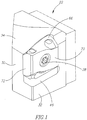
- the cutting tool 20 includes an insert holder 22 having an insert pocket 26 with a tangential cutting insert 24 removably retained in the insert pocket 26.
- the cutting tool 20 has a longitudinal axis A defining a forward to rearward direction, with the cutting insert 24 located at the forward end of the cutting tool 20.
- the cutting insert 24 is secured in the insert pocket 26 with a fastener 28.
- the insert holder 22 may be manufactured from a first material and the cutting insert 24 from a second harder material.
- the insert holder 22 has a holder front surface 30, a holder side surface 32, a holder upper surface 34 and the insert pocket 26.
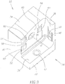
- the insert pocket 26 has a bottom surface 36, a rear surface 38 and a base surface 40.
- the base surface 40, the rear surface 38 and the bottom surface 36 may be mutually perpendicular to each other.
- the bottom surface 36 may be substantially planar.
- the bottom surface 36 may have a shim screw hole 42, having a central axis B, for receiving a shim screw 44 in order to secure a shim 46 to the bottom surface 36, as shown, for example, in US 7,073,987 .
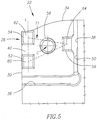
- the rear surface 38 may be substantially planar and has a rear abutment protuberance 48 projecting forwardly therefrom. As seen in Fig. 6 , the rear abutment protuberance 48 may be located adjacent the holder side surface 32 and approximately midway between the bottom surface 36 and the holder upper surface 34. The rear abutment protuberance 48 may have a rear abutment surface 50. The rear abutment surface 50 may be flat. The rear abutment protuberance 48 may be rectangular in shape.
- the base surface 40 may be substantially planar and is provided with three spaced apart base abutment protuberances, a first 52, second 54 and third 56 base abutment protuberance.
- the base surface 40 is also provided with an insert fastening hole 58, having a center C and a central axis D, the insert fastening hole 58 and the shim screw hole 42 in the bottom surface 36 being generally perpendicular to one another as seen in Fig. 3 . That is to say, the central axis B of the shim screw hole 42 and the central axis D of the insert fastening hole 58 are generally perpendicular to each other.
- the first and second base abutment protuberances 52, 54 are located between the holder front surface 30 and the insert fastening hole 58 and the third base abutment protuberance 56 is located between the insert fastening hole 58 and the rear surface 38 of the insert pocket 26.
- the first and second base abutment protuberances 52, 54 are aligned along a line L perpendicular to the bottom surface 36 with the second base abutment protuberance 54 being further from the bottom surface 36 than the third base abutment protuberance 56.
- the third base abutment protuberance 56 is located further from the bottom surface 36 than the first base abutment protuberance 52 and is substantially the same distance from the bottom surface 36 as the insert fastening hole 58.
- Each base abutment protuberance 52, 54, 56 comprises a respective base abutment surface 60, 62, 64 where each base abutment surface 60, 62, 64 is flat and the three base abutment surfaces 60, 62, 64 are coplanar.
- Each base abutment surface 60, 62, 64 may be rectangular in shape to form a stable abutment region.
- the base abutment surfaces 60, 62, 64 may be arranged relative to one another on the base surface 40 such that the center C of the insert fastening hole 58 lies within an imaginary triangle T1 connecting the centers of three base abutment surfaces 60, 62, 64.
- the three base abutment surfaces 60, 62, 64 be flat and coplanar, in some embodiments the three base abutments surfaces may each have a slightly convex surface which conforms to the contour of a corresponding portion of the insert recess 74 against which abutment occurs, as discussed below.
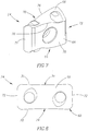
- the cutting insert 24 has two opposing end surfaces 66 and a peripheral side surface 68 extending between the two end surfaces 66.
- the peripheral side surface 68 includes two identical opposing major side surfaces 70 and two identical opposing minor side surfaces 72.
- each major side surface 70 of the cutting insert 24 is concave with a centrally situated recess 74 extending between the end surfaces 66.
- the major side surfaces 70 and the end surfaces 66 meet at major cutting edges 76.
- an operative major side surface 70, an operative minor side surface 72 and an operative end surface 66 of the cutting insert 24 engage the insert pocket 26 with the first and second base abutment surfaces 60, 62 abutting the operative major side surface 70 at respective first and second abutment regions on one side of the recess 74, the third base abutment surface 64 abutting the operative major side surface 70 at a third abutment region on the other side of the recess 74 and the rear abutment surface 50 abutting the operative minor side surface 72 at a fourth abutment region.
- the operative end surface 66 of the cutting insert 24 engages the shim 46.
- the three base abutment protuberances 52, 54, 56 provide stable seating for the cutting insert 24 even though the operative major side surface 70 of the cutting insert 24 is not planar.
Landscapes
- Engineering & Computer Science (AREA)
- Mechanical Engineering (AREA)
- Cutting Tools, Boring Holders, And Turrets (AREA)
Priority Applications (1)
| Application Number | Priority Date | Filing Date | Title |
|---|---|---|---|
| PL11784791T PL2640539T3 (pl) | 2010-11-17 | 2011-10-04 | Narzędzie skrawające i uchwyt na wkładkę dla stycznej wkładki skrawającej |
Applications Claiming Priority (2)
| Application Number | Priority Date | Filing Date | Title |
|---|---|---|---|
| IL209396A IL209396A (en) | 2010-11-17 | 2010-11-17 | Cutting tool and holding tool for tangential cutting job |
| PCT/IL2011/000773 WO2012066529A1 (en) | 2010-11-17 | 2011-10-04 | Cutting tool and insert holder for tangential cutting insert |
Publications (2)
| Publication Number | Publication Date |
|---|---|
| EP2640539A1 EP2640539A1 (en) | 2013-09-25 |
| EP2640539B1 true EP2640539B1 (en) | 2017-08-30 |
Family
ID=44718682
Family Applications (1)
| Application Number | Title | Priority Date | Filing Date |
|---|---|---|---|
| EP11784791.3A Active EP2640539B1 (en) | 2010-11-17 | 2011-10-04 | Cutting tool and insert holder for tangential cutting insert |
Country Status (12)
| Country | Link |
|---|---|
| US (1) | US8568065B2 (ko) |
| EP (1) | EP2640539B1 (ko) |
| JP (1) | JP5873878B2 (ko) |
| KR (1) | KR101639109B1 (ko) |
| CN (1) | CN103209795B (ko) |
| BR (1) | BR112013008485B1 (ko) |
| ES (1) | ES2647687T3 (ko) |
| IL (1) | IL209396A (ko) |
| PL (1) | PL2640539T3 (ko) |
| PT (1) | PT2640539T (ko) |
| RU (1) | RU2563613C2 (ko) |
| WO (1) | WO2012066529A1 (ko) |
Families Citing this family (14)
| Publication number | Priority date | Publication date | Assignee | Title |
|---|---|---|---|---|
| WO2011021104A1 (en) * | 2009-08-16 | 2011-02-24 | Carmex Precision Tools Ltd. | Insert, support, tool, and method |
| US8277153B2 (en) * | 2009-12-02 | 2012-10-02 | Kennametal Inc. | Cutting insert and shim for heavy machining operations |
| JP5906976B2 (ja) * | 2011-10-04 | 2016-04-20 | 三菱マテリアル株式会社 | 切削インサートおよび刃先交換式切削工具 |
| DE102012017025B4 (de) * | 2012-08-28 | 2018-05-30 | Kennametal Inc. | Werkzeughalter für einen Schneideinsatz und Baugruppe mit einem solchen Werkzeughalter |
| US9375793B2 (en) | 2013-10-29 | 2016-06-28 | Kennametal Inc. | Cutting insert for heavy machining operations |
| DE102013114124A1 (de) * | 2013-12-16 | 2015-06-18 | Hegenscheidt-Mfd Gmbh & Co. Kg | Schneideinsatz zum Profildrehen sowie Kassette zur Aufnahme eines Schneideinsatzes |
| PL3075477T3 (pl) | 2015-04-01 | 2019-03-29 | Ledermann Gmbh & Co. Kg | Frez i element skrawający do zastosowania we frezie |
| US9981323B2 (en) | 2015-07-16 | 2018-05-29 | Kennametal Inc. | Double-sided tangential cutting insert and cutting tool system using the same |
| USD778330S1 (en) | 2015-07-16 | 2017-02-07 | Kennametal Inc. | Double-sided tangential cutting insert |
| USD777230S1 (en) | 2015-07-16 | 2017-01-24 | Kennametal Inc | Double-sided tangential cutting insert |
| EP3246117A1 (en) * | 2016-05-20 | 2017-11-22 | Seco Tools Ab | Cutting tool and shim |
| US10005141B2 (en) * | 2016-08-04 | 2018-06-26 | Iscar, Ltd. | Tool holder having insert receiving pocket with stress relief surfaces |
| CN111050965B (zh) * | 2017-08-30 | 2021-04-09 | 三菱日立工具株式会社 | 切削刀片及可转位刀片式球头立铣刀 |
| CN110052627A (zh) * | 2018-11-16 | 2019-07-26 | 哈尔滨理工大学 | 一种可以安装多种刀片可转位车刀 |
Family Cites Families (16)
| Publication number | Priority date | Publication date | Assignee | Title |
|---|---|---|---|---|
| US3121939A (en) * | 1957-01-18 | 1964-02-25 | O K Tool Co Inc | Cutting tool with indexable bit |
| JPH06126511A (ja) * | 1992-10-13 | 1994-05-10 | Toyota Motor Corp | スローアウェイチップ |
| IL112818A (en) | 1995-02-28 | 1999-10-28 | Iscar Ltd | Tool holder having a grooved seat |
| SE509595C2 (sv) * | 1996-01-25 | 1999-02-15 | Sandvik Ab | Skär för spånavskiljande metallbearbetning |
| JP3402245B2 (ja) * | 1999-03-04 | 2003-05-06 | 住友電気工業株式会社 | スローアウェイチップのクランプ機構 |
| SE523224C2 (sv) * | 2001-11-21 | 2004-04-06 | Sandvik Ab | Roterbart skärverktyg |
| IL148535A (en) * | 2002-03-06 | 2009-02-11 | Gil Hecht | Metal cutting tool |
| RU2279332C2 (ru) * | 2004-08-12 | 2006-07-10 | Дмитрий Валерьевич Попов | Торцово-цилиндрическая фреза |
| US7104735B2 (en) * | 2004-09-02 | 2006-09-12 | Ingersoll Cutting Tool Company | Tangential cutting insert and milling cutter |
| SE528811C2 (sv) * | 2005-03-16 | 2007-02-20 | Sandvik Intellectual Property | Skär och verktyg för spånavskiljande bearbetning med vinklade ingreppsmedel, samt tillsats för dylika verktyg |
| SE528751C2 (sv) * | 2005-06-27 | 2007-02-06 | Sandvik Intellectual Property | Svarvverktyg och indexerbart svarvskär, samt tillsats för dylika svarvverktyg |
| US7429150B2 (en) | 2006-05-31 | 2008-09-30 | Kennametal Inc. | Tool holder with spherical contact points |
| SE530808C2 (sv) * | 2007-01-31 | 2008-09-16 | Sandvik Intellectual Property | Verktyg för spånavskiljande bearbetning, samt skär och grundkropp härför |
| RU2342225C1 (ru) * | 2007-08-06 | 2008-12-27 | Нина Алексеевна Корюкина | Сборный режущий инструмент |
| RU2372168C1 (ru) * | 2008-07-14 | 2009-11-10 | Нина Алексеевна Корюкина | Режущая пластина и сборный режущий инструмент |
| IL197898A0 (en) * | 2009-04-05 | 2009-12-24 | Iscar Ltd | Cutting insert and cutting tool therefor |
-
2010
- 2010-11-17 IL IL209396A patent/IL209396A/en active IP Right Grant
-
2011
- 2011-09-22 US US13/240,029 patent/US8568065B2/en active Active
- 2011-10-04 RU RU2013127216/02A patent/RU2563613C2/ru active
- 2011-10-04 KR KR1020137012118A patent/KR101639109B1/ko active IP Right Grant
- 2011-10-04 WO PCT/IL2011/000773 patent/WO2012066529A1/en active Application Filing
- 2011-10-04 PT PT117847913T patent/PT2640539T/pt unknown
- 2011-10-04 BR BR112013008485-5A patent/BR112013008485B1/pt active IP Right Grant
- 2011-10-04 JP JP2013539395A patent/JP5873878B2/ja active Active
- 2011-10-04 EP EP11784791.3A patent/EP2640539B1/en active Active
- 2011-10-04 PL PL11784791T patent/PL2640539T3/pl unknown
- 2011-10-04 CN CN201180055219.6A patent/CN103209795B/zh active Active
- 2011-10-04 ES ES11784791.3T patent/ES2647687T3/es active Active
Non-Patent Citations (1)
| Title |
|---|
| None * |
Also Published As
| Publication number | Publication date |
|---|---|
| KR20130122743A (ko) | 2013-11-08 |
| US8568065B2 (en) | 2013-10-29 |
| RU2013127216A (ru) | 2014-12-27 |
| ES2647687T3 (es) | 2017-12-26 |
| IL209396A (en) | 2015-03-31 |
| EP2640539A1 (en) | 2013-09-25 |
| PT2640539T (pt) | 2017-10-03 |
| WO2012066529A1 (en) | 2012-05-24 |
| CN103209795A (zh) | 2013-07-17 |
| IL209396A0 (en) | 2011-01-31 |
| KR101639109B1 (ko) | 2016-07-12 |
| RU2563613C2 (ru) | 2015-09-20 |
| CN103209795B (zh) | 2016-03-23 |
| JP2013542862A (ja) | 2013-11-28 |
| JP5873878B2 (ja) | 2016-03-01 |
| BR112013008485B1 (pt) | 2020-06-16 |
| PL2640539T3 (pl) | 2018-01-31 |
| BR112013008485A2 (pt) | 2016-08-09 |
| US20120121345A1 (en) | 2012-05-17 |
Similar Documents
| Publication | Publication Date | Title |
|---|---|---|
| EP2640539B1 (en) | Cutting tool and insert holder for tangential cutting insert | |
| CN101668605B (zh) | 以八种方式切削的切削镶片以及用于这种切削镶片的刀夹具 | |
| KR101052658B1 (ko) | 날끝 교환식 팁 및 그것을 이용한 절삭 공구 | |
| CN104159689B (zh) | 切削工具及其切削刀片 | |
| EP2519370B1 (en) | Cutting tool and double-ended cutting insert therefor | |
| KR101323558B1 (ko) | 장착 구멍을 갖는 인서트 및 절삭 인서트를 포함하는공구홀더 | |
| JP5475865B2 (ja) | 切削工具とそれのための切削インサート | |
| US9079252B2 (en) | Cutting tool with indexable cutting insert having non-abutting side flanks | |
| CN103140315B (zh) | 销铣刀插入件和使用该插入件的刀具 | |
| MX2007006713A (es) | Herramienta de corte e inserto de corte de la misma. | |
| CA2742214A1 (en) | Cutting tool and cutting insert therefor | |
| IL161373A (en) | Cutting tool and cutting tool for it | |
| JP2012524665A (ja) | 切削工具およびそのための切削インサート | |
| US20150246396A1 (en) | Tool holder for tangential cutting insert | |
| CA2789003C (en) | Cutting insert and cutting tool | |
| CN101623768B (zh) | 带轮加工用刀具及安装其的切削工具组件 | |
| JP2023144528A (ja) | 切削インサートのクランプ構造、サポーターおよび刃先交換式切削工具 | |
| JP2014046435A (ja) | 切削インサート及びそれを用いた切削工具 |
Legal Events
| Date | Code | Title | Description |
|---|---|---|---|
| PUAI | Public reference made under article 153(3) epc to a published international application that has entered the european phase |
Free format text: ORIGINAL CODE: 0009012 |
|
| 17P | Request for examination filed |
Effective date: 20130515 |
|
| AK | Designated contracting states |
Kind code of ref document: A1 Designated state(s): AL AT BE BG CH CY CZ DE DK EE ES FI FR GB GR HR HU IE IS IT LI LT LU LV MC MK MT NL NO PL PT RO RS SE SI SK SM TR |
|
| DAX | Request for extension of the european patent (deleted) | ||
| 17Q | First examination report despatched |
Effective date: 20150929 |
|
| GRAP | Despatch of communication of intention to grant a patent |
Free format text: ORIGINAL CODE: EPIDOSNIGR1 |
|
| INTG | Intention to grant announced |
Effective date: 20161026 |
|
| GRAS | Grant fee paid |
Free format text: ORIGINAL CODE: EPIDOSNIGR3 |
|
| GRAJ | Information related to disapproval of communication of intention to grant by the applicant or resumption of examination proceedings by the epo deleted |
Free format text: ORIGINAL CODE: EPIDOSDIGR1 |
|
| GRAL | Information related to payment of fee for publishing/printing deleted |
Free format text: ORIGINAL CODE: EPIDOSDIGR3 |
|
| GRAP | Despatch of communication of intention to grant a patent |
Free format text: ORIGINAL CODE: EPIDOSNIGR1 |
|
| INTC | Intention to grant announced (deleted) | ||
| INTG | Intention to grant announced |
Effective date: 20170403 |
|
| GRAA | (expected) grant |
Free format text: ORIGINAL CODE: 0009210 |
|
| AK | Designated contracting states |
Kind code of ref document: B1 Designated state(s): AL AT BE BG CH CY CZ DE DK EE ES FI FR GB GR HR HU IE IS IT LI LT LU LV MC MK MT NL NO PL PT RO RS SE SI SK SM TR |
|
| REG | Reference to a national code |
Ref country code: GB Ref legal event code: FG4D |
|
| REG | Reference to a national code |
Ref country code: CH Ref legal event code: EP |
|
| REG | Reference to a national code |
Ref country code: AT Ref legal event code: REF Ref document number: 923042 Country of ref document: AT Kind code of ref document: T Effective date: 20170915 Ref country code: FR Ref legal event code: PLFP Year of fee payment: 7 |
|
| REG | Reference to a national code |
Ref country code: IE Ref legal event code: FG4D |
|
| REG | Reference to a national code |
Ref country code: PT Ref legal event code: SC4A Ref document number: 2640539 Country of ref document: PT Date of ref document: 20171003 Kind code of ref document: T Free format text: AVAILABILITY OF NATIONAL TRANSLATION Effective date: 20170925 |
|
| REG | Reference to a national code |
Ref country code: DE Ref legal event code: R096 Ref document number: 602011041120 Country of ref document: DE |
|
| REG | Reference to a national code |
Ref country code: SE Ref legal event code: TRGR |
|
| REG | Reference to a national code |
Ref country code: ES Ref legal event code: FG2A Ref document number: 2647687 Country of ref document: ES Kind code of ref document: T3 Effective date: 20171226 |
|
| REG | Reference to a national code |
Ref country code: NL Ref legal event code: MP Effective date: 20170830 |
|
| REG | Reference to a national code |
Ref country code: LT Ref legal event code: MG4D |
|
| PG25 | Lapsed in a contracting state [announced via postgrant information from national office to epo] |
Ref country code: LT Free format text: LAPSE BECAUSE OF FAILURE TO SUBMIT A TRANSLATION OF THE DESCRIPTION OR TO PAY THE FEE WITHIN THE PRESCRIBED TIME-LIMIT Effective date: 20170830 Ref country code: FI Free format text: LAPSE BECAUSE OF FAILURE TO SUBMIT A TRANSLATION OF THE DESCRIPTION OR TO PAY THE FEE WITHIN THE PRESCRIBED TIME-LIMIT Effective date: 20170830 Ref country code: HR Free format text: LAPSE BECAUSE OF FAILURE TO SUBMIT A TRANSLATION OF THE DESCRIPTION OR TO PAY THE FEE WITHIN THE PRESCRIBED TIME-LIMIT Effective date: 20170830 Ref country code: NO Free format text: LAPSE BECAUSE OF FAILURE TO SUBMIT A TRANSLATION OF THE DESCRIPTION OR TO PAY THE FEE WITHIN THE PRESCRIBED TIME-LIMIT Effective date: 20171130 |
|
| PG25 | Lapsed in a contracting state [announced via postgrant information from national office to epo] |
Ref country code: IS Free format text: LAPSE BECAUSE OF FAILURE TO SUBMIT A TRANSLATION OF THE DESCRIPTION OR TO PAY THE FEE WITHIN THE PRESCRIBED TIME-LIMIT Effective date: 20171230 Ref country code: BG Free format text: LAPSE BECAUSE OF FAILURE TO SUBMIT A TRANSLATION OF THE DESCRIPTION OR TO PAY THE FEE WITHIN THE PRESCRIBED TIME-LIMIT Effective date: 20171130 Ref country code: GR Free format text: LAPSE BECAUSE OF FAILURE TO SUBMIT A TRANSLATION OF THE DESCRIPTION OR TO PAY THE FEE WITHIN THE PRESCRIBED TIME-LIMIT Effective date: 20171201 Ref country code: LV Free format text: LAPSE BECAUSE OF FAILURE TO SUBMIT A TRANSLATION OF THE DESCRIPTION OR TO PAY THE FEE WITHIN THE PRESCRIBED TIME-LIMIT Effective date: 20170830 Ref country code: RS Free format text: LAPSE BECAUSE OF FAILURE TO SUBMIT A TRANSLATION OF THE DESCRIPTION OR TO PAY THE FEE WITHIN THE PRESCRIBED TIME-LIMIT Effective date: 20170830 |
|
| PG25 | Lapsed in a contracting state [announced via postgrant information from national office to epo] |
Ref country code: NL Free format text: LAPSE BECAUSE OF FAILURE TO SUBMIT A TRANSLATION OF THE DESCRIPTION OR TO PAY THE FEE WITHIN THE PRESCRIBED TIME-LIMIT Effective date: 20170830 |
|
| PG25 | Lapsed in a contracting state [announced via postgrant information from national office to epo] |
Ref country code: RO Free format text: LAPSE BECAUSE OF FAILURE TO SUBMIT A TRANSLATION OF THE DESCRIPTION OR TO PAY THE FEE WITHIN THE PRESCRIBED TIME-LIMIT Effective date: 20170830 Ref country code: DK Free format text: LAPSE BECAUSE OF FAILURE TO SUBMIT A TRANSLATION OF THE DESCRIPTION OR TO PAY THE FEE WITHIN THE PRESCRIBED TIME-LIMIT Effective date: 20170830 |
|
| PG25 | Lapsed in a contracting state [announced via postgrant information from national office to epo] |
Ref country code: SK Free format text: LAPSE BECAUSE OF FAILURE TO SUBMIT A TRANSLATION OF THE DESCRIPTION OR TO PAY THE FEE WITHIN THE PRESCRIBED TIME-LIMIT Effective date: 20170830 Ref country code: SM Free format text: LAPSE BECAUSE OF FAILURE TO SUBMIT A TRANSLATION OF THE DESCRIPTION OR TO PAY THE FEE WITHIN THE PRESCRIBED TIME-LIMIT Effective date: 20170830 Ref country code: EE Free format text: LAPSE BECAUSE OF FAILURE TO SUBMIT A TRANSLATION OF THE DESCRIPTION OR TO PAY THE FEE WITHIN THE PRESCRIBED TIME-LIMIT Effective date: 20170830 Ref country code: MC Free format text: LAPSE BECAUSE OF FAILURE TO SUBMIT A TRANSLATION OF THE DESCRIPTION OR TO PAY THE FEE WITHIN THE PRESCRIBED TIME-LIMIT Effective date: 20170830 |
|
| REG | Reference to a national code |
Ref country code: CH Ref legal event code: PL Ref country code: DE Ref legal event code: R097 Ref document number: 602011041120 Country of ref document: DE |
|
| PLBE | No opposition filed within time limit |
Free format text: ORIGINAL CODE: 0009261 |
|
| STAA | Information on the status of an ep patent application or granted ep patent |
Free format text: STATUS: NO OPPOSITION FILED WITHIN TIME LIMIT |
|
| REG | Reference to a national code |
Ref country code: IE Ref legal event code: MM4A |
|
| PG25 | Lapsed in a contracting state [announced via postgrant information from national office to epo] |
Ref country code: CH Free format text: LAPSE BECAUSE OF NON-PAYMENT OF DUE FEES Effective date: 20171031 Ref country code: LU Free format text: LAPSE BECAUSE OF NON-PAYMENT OF DUE FEES Effective date: 20171004 Ref country code: LI Free format text: LAPSE BECAUSE OF NON-PAYMENT OF DUE FEES Effective date: 20171031 |
|
| 26N | No opposition filed |
Effective date: 20180531 |
|
| REG | Reference to a national code |
Ref country code: BE Ref legal event code: MM Effective date: 20171031 |
|
| PG25 | Lapsed in a contracting state [announced via postgrant information from national office to epo] |
Ref country code: SI Free format text: LAPSE BECAUSE OF FAILURE TO SUBMIT A TRANSLATION OF THE DESCRIPTION OR TO PAY THE FEE WITHIN THE PRESCRIBED TIME-LIMIT Effective date: 20170830 Ref country code: BE Free format text: LAPSE BECAUSE OF NON-PAYMENT OF DUE FEES Effective date: 20171031 |
|
| REG | Reference to a national code |
Ref country code: FR Ref legal event code: PLFP Year of fee payment: 8 |
|
| PG25 | Lapsed in a contracting state [announced via postgrant information from national office to epo] |
Ref country code: MT Free format text: LAPSE BECAUSE OF NON-PAYMENT OF DUE FEES Effective date: 20171004 |
|
| PG25 | Lapsed in a contracting state [announced via postgrant information from national office to epo] |
Ref country code: IE Free format text: LAPSE BECAUSE OF NON-PAYMENT OF DUE FEES Effective date: 20171004 |
|
| REG | Reference to a national code |
Ref country code: AT Ref legal event code: UEP Ref document number: 923042 Country of ref document: AT Kind code of ref document: T Effective date: 20170830 |
|
| PG25 | Lapsed in a contracting state [announced via postgrant information from national office to epo] |
Ref country code: HU Free format text: LAPSE BECAUSE OF FAILURE TO SUBMIT A TRANSLATION OF THE DESCRIPTION OR TO PAY THE FEE WITHIN THE PRESCRIBED TIME-LIMIT; INVALID AB INITIO Effective date: 20111004 |
|
| PG25 | Lapsed in a contracting state [announced via postgrant information from national office to epo] |
Ref country code: CY Free format text: LAPSE BECAUSE OF NON-PAYMENT OF DUE FEES Effective date: 20170830 |
|
| PG25 | Lapsed in a contracting state [announced via postgrant information from national office to epo] |
Ref country code: MK Free format text: LAPSE BECAUSE OF FAILURE TO SUBMIT A TRANSLATION OF THE DESCRIPTION OR TO PAY THE FEE WITHIN THE PRESCRIBED TIME-LIMIT Effective date: 20170830 |
|
| PG25 | Lapsed in a contracting state [announced via postgrant information from national office to epo] |
Ref country code: AL Free format text: LAPSE BECAUSE OF FAILURE TO SUBMIT A TRANSLATION OF THE DESCRIPTION OR TO PAY THE FEE WITHIN THE PRESCRIBED TIME-LIMIT Effective date: 20170830 |
|
| PGFP | Annual fee paid to national office [announced via postgrant information from national office to epo] |
Ref country code: TR Payment date: 20230824 Year of fee payment: 13 Ref country code: IT Payment date: 20230821 Year of fee payment: 13 Ref country code: GB Payment date: 20230911 Year of fee payment: 13 Ref country code: CZ Payment date: 20230908 Year of fee payment: 13 |
|
| PGFP | Annual fee paid to national office [announced via postgrant information from national office to epo] |
Ref country code: SE Payment date: 20230905 Year of fee payment: 13 Ref country code: PT Payment date: 20230829 Year of fee payment: 13 Ref country code: PL Payment date: 20230824 Year of fee payment: 13 Ref country code: FR Payment date: 20230907 Year of fee payment: 13 |
|
| PGFP | Annual fee paid to national office [announced via postgrant information from national office to epo] |
Ref country code: ES Payment date: 20231117 Year of fee payment: 13 |
|
| PGFP | Annual fee paid to national office [announced via postgrant information from national office to epo] |
Ref country code: DE Payment date: 20230907 Year of fee payment: 13 Ref country code: AT Payment date: 20230906 Year of fee payment: 13 |