EP2640504B1 - Chemischer reaktor mit drahtgestrick-maschenware als halteeinrichtung für partikel - Google Patents
Chemischer reaktor mit drahtgestrick-maschenware als halteeinrichtung für partikel Download PDFInfo
- Publication number
- EP2640504B1 EP2640504B1 EP11785384.6A EP11785384A EP2640504B1 EP 2640504 B1 EP2640504 B1 EP 2640504B1 EP 11785384 A EP11785384 A EP 11785384A EP 2640504 B1 EP2640504 B1 EP 2640504B1
- Authority
- EP
- European Patent Office
- Prior art keywords
- reactor
- particles
- knitted fabric
- wire mesh
- catalyst
- Prior art date
- Legal status (The legal status is an assumption and is not a legal conclusion. Google has not performed a legal analysis and makes no representation as to the accuracy of the status listed.)
- Active
Links
Images

Classifications
-
- B—PERFORMING OPERATIONS; TRANSPORTING
- B01—PHYSICAL OR CHEMICAL PROCESSES OR APPARATUS IN GENERAL
- B01J—CHEMICAL OR PHYSICAL PROCESSES, e.g. CATALYSIS OR COLLOID CHEMISTRY; THEIR RELEVANT APPARATUS
- B01J8/00—Chemical or physical processes in general, conducted in the presence of fluids and solid particles; Apparatus for such processes
- B01J8/02—Chemical or physical processes in general, conducted in the presence of fluids and solid particles; Apparatus for such processes with stationary particles, e.g. in fixed beds
- B01J8/0292—Chemical or physical processes in general, conducted in the presence of fluids and solid particles; Apparatus for such processes with stationary particles, e.g. in fixed beds with stationary packing material in the bed, e.g. bricks, wire rings, baffles
-
- B—PERFORMING OPERATIONS; TRANSPORTING
- B01—PHYSICAL OR CHEMICAL PROCESSES OR APPARATUS IN GENERAL
- B01J—CHEMICAL OR PHYSICAL PROCESSES, e.g. CATALYSIS OR COLLOID CHEMISTRY; THEIR RELEVANT APPARATUS
- B01J8/00—Chemical or physical processes in general, conducted in the presence of fluids and solid particles; Apparatus for such processes
- B01J8/02—Chemical or physical processes in general, conducted in the presence of fluids and solid particles; Apparatus for such processes with stationary particles, e.g. in fixed beds
- B01J8/0242—Chemical or physical processes in general, conducted in the presence of fluids and solid particles; Apparatus for such processes with stationary particles, e.g. in fixed beds the fluid flow within the bed being predominantly vertical
-
- B—PERFORMING OPERATIONS; TRANSPORTING
- B01—PHYSICAL OR CHEMICAL PROCESSES OR APPARATUS IN GENERAL
- B01J—CHEMICAL OR PHYSICAL PROCESSES, e.g. CATALYSIS OR COLLOID CHEMISTRY; THEIR RELEVANT APPARATUS
- B01J8/00—Chemical or physical processes in general, conducted in the presence of fluids and solid particles; Apparatus for such processes
- B01J8/008—Details of the reactor or of the particulate material; Processes to increase or to retard the rate of reaction
-
- B—PERFORMING OPERATIONS; TRANSPORTING
- B01—PHYSICAL OR CHEMICAL PROCESSES OR APPARATUS IN GENERAL
- B01J—CHEMICAL OR PHYSICAL PROCESSES, e.g. CATALYSIS OR COLLOID CHEMISTRY; THEIR RELEVANT APPARATUS
- B01J8/00—Chemical or physical processes in general, conducted in the presence of fluids and solid particles; Apparatus for such processes
- B01J8/02—Chemical or physical processes in general, conducted in the presence of fluids and solid particles; Apparatus for such processes with stationary particles, e.g. in fixed beds
- B01J8/0242—Chemical or physical processes in general, conducted in the presence of fluids and solid particles; Apparatus for such processes with stationary particles, e.g. in fixed beds the fluid flow within the bed being predominantly vertical
- B01J8/025—Chemical or physical processes in general, conducted in the presence of fluids and solid particles; Apparatus for such processes with stationary particles, e.g. in fixed beds the fluid flow within the bed being predominantly vertical in a cylindrical shaped bed
-
- B—PERFORMING OPERATIONS; TRANSPORTING
- B01—PHYSICAL OR CHEMICAL PROCESSES OR APPARATUS IN GENERAL
- B01J—CHEMICAL OR PHYSICAL PROCESSES, e.g. CATALYSIS OR COLLOID CHEMISTRY; THEIR RELEVANT APPARATUS
- B01J8/00—Chemical or physical processes in general, conducted in the presence of fluids and solid particles; Apparatus for such processes
- B01J8/18—Chemical or physical processes in general, conducted in the presence of fluids and solid particles; Apparatus for such processes with fluidised particles
- B01J8/24—Chemical or physical processes in general, conducted in the presence of fluids and solid particles; Apparatus for such processes with fluidised particles according to "fluidised-bed" technique
- B01J8/44—Fluidisation grids
-
- C—CHEMISTRY; METALLURGY
- C07—ORGANIC CHEMISTRY
- C07C—ACYCLIC OR CARBOCYCLIC COMPOUNDS
- C07C209/00—Preparation of compounds containing amino groups bound to a carbon skeleton
- C07C209/30—Preparation of compounds containing amino groups bound to a carbon skeleton by reduction of nitrogen-to-oxygen or nitrogen-to-nitrogen bonds
- C07C209/32—Preparation of compounds containing amino groups bound to a carbon skeleton by reduction of nitrogen-to-oxygen or nitrogen-to-nitrogen bonds by reduction of nitro groups
- C07C209/36—Preparation of compounds containing amino groups bound to a carbon skeleton by reduction of nitrogen-to-oxygen or nitrogen-to-nitrogen bonds by reduction of nitro groups by reduction of nitro groups bound to carbon atoms of six-membered aromatic rings in presence of hydrogen-containing gases and a catalyst
-
- D—TEXTILES; PAPER
- D04—BRAIDING; LACE-MAKING; KNITTING; TRIMMINGS; NON-WOVEN FABRICS
- D04B—KNITTING
- D04B1/00—Weft knitting processes for the production of fabrics or articles not dependent on the use of particular machines; Fabrics or articles defined by such processes
- D04B1/14—Other fabrics or articles characterised primarily by the use of particular thread materials
-
- B—PERFORMING OPERATIONS; TRANSPORTING
- B01—PHYSICAL OR CHEMICAL PROCESSES OR APPARATUS IN GENERAL
- B01J—CHEMICAL OR PHYSICAL PROCESSES, e.g. CATALYSIS OR COLLOID CHEMISTRY; THEIR RELEVANT APPARATUS
- B01J2208/00—Processes carried out in the presence of solid particles; Reactors therefor
- B01J2208/00796—Details of the reactor or of the particulate material
- B01J2208/00884—Means for supporting the bed of particles, e.g. grids, bars, perforated plates
-
- Y—GENERAL TAGGING OF NEW TECHNOLOGICAL DEVELOPMENTS; GENERAL TAGGING OF CROSS-SECTIONAL TECHNOLOGIES SPANNING OVER SEVERAL SECTIONS OF THE IPC; TECHNICAL SUBJECTS COVERED BY FORMER USPC CROSS-REFERENCE ART COLLECTIONS [XRACs] AND DIGESTS
- Y02—TECHNOLOGIES OR APPLICATIONS FOR MITIGATION OR ADAPTATION AGAINST CLIMATE CHANGE
- Y02P—CLIMATE CHANGE MITIGATION TECHNOLOGIES IN THE PRODUCTION OR PROCESSING OF GOODS
- Y02P70/00—Climate change mitigation technologies in the production process for final industrial or consumer products
- Y02P70/50—Manufacturing or production processes characterised by the final manufactured product
- Y02P70/62—Manufacturing or production processes characterised by the final manufactured product related technologies for production or treatment of textile or flexible materials or products thereof, including footwear
-
- Y—GENERAL TAGGING OF NEW TECHNOLOGICAL DEVELOPMENTS; GENERAL TAGGING OF CROSS-SECTIONAL TECHNOLOGIES SPANNING OVER SEVERAL SECTIONS OF THE IPC; TECHNICAL SUBJECTS COVERED BY FORMER USPC CROSS-REFERENCE ART COLLECTIONS [XRACs] AND DIGESTS
- Y10—TECHNICAL SUBJECTS COVERED BY FORMER USPC
- Y10T—TECHNICAL SUBJECTS COVERED BY FORMER US CLASSIFICATION
- Y10T428/00—Stock material or miscellaneous articles
- Y10T428/12—All metal or with adjacent metals
- Y10T428/12424—Mass of only fibers
Definitions
- the present invention relates to a chemical reactor for heterogeneously catalyzed reaction of a fluid with an improved holding device for fluid-flow inert particles and / or catalyst particles. It further relates to a method for carrying out chemical reactions by means of such a reactor and the use of knitted wire mesh in chemical reactors.
- the hydrogenation of nitroaromatics to the corresponding amines in an axially flowing fixed bed reactor can be carried out in a multi-stage process under adiabatic reaction conditions. Such hydrogenations run in periodic cycles, with production cycles alternating with regeneration cycles in which, for example, carbonaceous deposits are removed by burning off.
- Reactors for such reactions typically have a cylindrical shape and are equipped with a slotted screen as a support for the Fixed bed catalyst is used (Heterogeneous Catalysis in Industrial Practice, 2nd Ed., 1996, page 474 ). These slot screens must support the weight of the catalyst as well as the additional stress resulting from the pressure drop across the catalyst bed.
- Spaltsiebe as for example in US 2,915,375 to be discribed. They consist of parallel arranged V-shaped wires, which in turn are supported and fixed again, so that there are gaps whose width is smaller than the grain size of the material to be supported and widening down to possibly between the wires passing material dissipate downwards and to avoid clogging of the gap sieve.
- the screen Due to the periodic operation of the reactors, the screen is subjected to thermal stresses which lead to damage. This is the case in particular when exothermic reactions are carried out under adiabatic conditions, that is, the reaction heat released is absorbed by the reaction gas, so that large temperature jumps occur in the interior of the reactor.
- the gap sieves are usually at one attached floating support ring, which has a gap to the reactor wall to compensate for thermal expansion.
- the catalyst can be stored on a complex, multi-layer bed of inert particles, wherein the particle diameter in the layer closest to the catalyst is slightly larger than the particle diameter of the catalyst and then increases with each layer (Fixed-Bed Reactor Design and Diagnostics, 1990, Fig. 1.1 , Page 4).
- a chemical reactor for the heterogeneously catalyzed reaction of a fluid comprising a holding device for particles through which fluid flows, wherein the upstream side of the holding device, viewed in the flow direction of the fluid, comprises knitted wire mesh on which catalyst particles are arranged or on which a layer of particles inert to the fluid is arranged and arranged on this layer of catalyst particles, wherein the knitted fabric knitted fabric is arranged on a support and the carrier in the flow direction of the fluid through openings comprises, and wherein the average clear mesh size of the wire mesh smaller than that mean particle size X 50.3 of the particles which is determined by a sieve analysis carried out with a vibrating sieve with sieve set in compliance with the provisions of DIN 66165 (version of April 1987).
- Knitted fabrics are known for example from the textile and jewelry industry. More generally, a knit fabric refers to a fabric in which a loop formed by means of a thread or a plurality of threads is looped into another loop to form the "stitches". This should be distinguished from fabrics in which the surface is made by crossing two thread systems. Knitted fabric has a higher extensibility and elasticity than fabric. Knitwear can be divided into knit, knitting and weft. In principle, all three are suitable for carrying out the present invention. However, particularly preferred knitting and / or Kulierwaren be used, since they are even more elastic than the (already elastic) hosiery.
- a knitted fabric knitted fabric is used, ie the knit fabric according to the invention is made of wires and / or metal threads.
- the term in the context of the present invention includes "wire knitted fabric” all kinds of knitted fabrics, including knitted fabric.
- the production of the wire knit takes place with wire processing machines known per se, such as are commonly used for applications in the automotive industry, process engineering and environmental technology (eg wire knitting machines).
- Wire knits from DHD Technology, for example, are suitable for carrying out the present invention.
- the flexibility of the knit fabric ensures that it is not damaged during periodic operation at different temperatures. At the same time, the 3-dimensional structure of the knitted fabric prevents too much mesh with particles and obstructs the gas flow.
- particles can be understood as meaning both catalyst particles (for example a noble metal catalyst supported on aluminum oxide spheres) and inert particles (for example aluminum oxide spheres).
- particles are used which are at least substantially spherical, that is, whose possibly existing deviations from the ideal spherical geometry are so small that they behave in practice as ideal spheres. in principle However, the invention is also applicable to asymmetrically shaped particles.
- the first indication of the average particle size is provided by the manufacturer.
- a "particle size analysis” is required. In the context of this invention, this is done by sieve analysis. According to the invention, the mass-related value (“x 50.3 ”) is used as mean particle size.
- the procedure is now to first subject a representative sample of the particles to be supported to a sieve analysis and to evaluate the result on a mass basis.
- Sieve analysis is carried out using a vibrating sieve machine (eg model AS 200 digit from Retsch) in which the test sieves are arranged one above the other with increasing mesh size to form a sieve.
- the selection of the test sieves depends primarily on the amount of screenings and the expected (if necessary preliminary tests are necessary) particle size distribution.
- the number of sieves and the gradations of the nominal opening widths should be selected so that as far as possible the entire particle spectrum of the sample is divided into fractions.
- the sieve analysis yields as a result the particle size distribution of the measured particles.
- the result is preferably plotted by plotting the mass fraction of the individual fractions ("p 3 ”) in a bar graph and the cumulative cumulative cumulative curve ("Q 3 ") over the nominal sieve opening widths (x).
- the person skilled in the art can easily calculate the mean particle size x 50.3 (ie 50% by mass of the particles are smaller than the corresponding value x), either manually or preferably by computer-assisted evaluation programs.
- the average particle size determined in this way is x 50.3 of the value required for carrying out the invention.
- the particle size distribution is monomodal and that in each case a maximum of 0.1% by mass of all particles in the range between 1 ⁇ 2 x 50.3 and 2/3 of x in the range between 50.3 and 11 ⁇ 3 x 50 3 and 11 ⁇ 2 x 50.3 lie.
- particles should not be smaller than 1 ⁇ 2 x 50.3 or larger than 11 ⁇ 2 x 50.3 .
- the chemical reactor can be, for example, an axially flow-through fixed bed reactor, as used in the hydrogenation of nitrobenzene to aniline.
- the fluid to be reacted in the reactor can be liquid, gaseous or supercritical. It may contain a reactant or a mixture of several reactants.
- the particles retained by the knitted fabric can be both catalyst particles and inert particles.
- the type of knitted fabric knitted fabric is initially not specified. It may be single-wire or multi-wire, which has been entangled in any way.
- the knitted fabrics may contain up to 5 round, flat, smooth and / or wavy threads.
- Enmeshed materials may include steel, stainless steels such as 1.4571, copper, Monel (2.4360) or aluminum.
- two-layer wire knitting paths can be used, which result from the compression of wire knit hoses, which are made with circular knitting machines with respect to a running through the center axis of the wire knit hoses folding level.
- the average clear mesh width of the wire mesh is smaller than the mean particle size x 50.3 of the particles which are intended to be received in the holding device. It denotes the inside distance (not the distance from the middle of the wire to the center of the wire) of two adjacent mesh legs at the point of greatest expansion of a mesh. Preferably, the ratio between mesh length, ie the distance between two adjacent mesh heads, and mesh size between 4: 1 and 0.5: 1, more preferably between 2: 1 and 1: 1.
- the average clear mesh then denotes the average value of all clear widths of individual Mesh of a knitted knitted fabric.
- the average clear mesh size is set in the production of knitted wire knit fabric by methods known to the person skilled in the art (eg number, spacing and thickness of the needles on the knitting head, number and thickness of the wires, etc.).
- the use of non-uniform mesh sizes ie, differences in mesh sizes that exceed normal manufacturing tolerances) is not preferred, but generally possible.
- the clear mesh size of the largest mesh is preferably smaller than the mean particle size x 50.3 .
- the holding device for particles can be formed in the simplest case by knitted fabric knitted in the reactor alone. However, it is preferred that the knit knitted fabric be supported by a carrier to cope with the mechanical stresses involved. Then both the carrier and the knitted fabric are part of the holding device for particles. Together with catalyst particles, the catalyst bed is formed from this.
- the position of the knitted fabric in the holding device for particles in the reactor through which the fluid flows results from the function of the knitwear for the retention of particles. It is therefore located on the upstream side of the holding device.
- An advantage of the reactor according to the invention is further that a simple slotted screen can be used as a carrier.
- the use of an elaborate slotted screen is not required, but it can also be a simple rust used.
- the knitwear is placed on the slotted screen or the grate and optionally fixed.
- the laid-up knitwear now assumes the function of catalyst retention. As a result, not only damage to the slotted screen can be accepted, but the openings in the slotted screen can be made larger from the outset.
- the average mesh size of the wire mesh is ⁇ 20% to ⁇ 80% of the mean particle size ⁇ 50.3 .
- This value is preferably ⁇ 30% to ⁇ 60%, and more preferably ⁇ 40% to ⁇ 50%. In this way it is particularly prevented that an undesired pressure loss occurs during operation of the reactor due to particles caught in the mesh.
- the extensibility of the knitted wire knit fabric under mechanical and / or thermal stress in the surface direction is ⁇ 1%, preferably ⁇ 2%. The extensibility in the plane direction should not exceed 50%, preferably 25%, preferably 10%.
- the wire diameter of the knit knitted fabric is ⁇ 0.03 mm to ⁇ 1 mm.
- the diameter of the wire from which the knitted fabric is knitted is ⁇ 0.1 mm to ⁇ 0.5 mm, and more preferably ⁇ 0.2 mm to ⁇ 0.3 mm. In this way it is particularly ensured that the wire has sufficient stability with low weight and large passage area for the fluid.
- the height of the knitted wire knitted fabric in the holding device for particles is ⁇ 3 mm to ⁇ 100 mm.
- the knitted wire knitted fabric is a knitted fabric knitted by mechanical action.
- the knitted fabric can be rolled or passed between two cylindrical rollers or gears.
- the knitted fabric is arranged on a support and the support comprises in the direction of flow of the fluid through openings.
- preferred carriers are slot screens and gratings.
- the carrier can be stored on a support ring floating on the inside of the reactor wall to compensate for the thermal expansion during operation.
- knitted wire mesh is arranged.
- this knitted fabric knitted fabric is a metallic sealing cord made of knitwear. It is favorable if it consists of the same material as the knitwear on the carrier.
- the wire mesh knitwear additionally located between the support and the wall of the reactor is arranged in a U shape and an elastically prestressed further knitted wire knit fabric is introduced into the depression formed thereby.
- this may be a metallic sealing cord made of knitwear.
- the legs of the "U” can each stand alone or together vertically, for example, to be adapted to the shape of the reactor wall. But it is also possible that the legs take at least partially a horizontal course.
- the type of bias can be both compression and elongation.
- the sealing cord is compressed prior to insertion, so that it then expands. Then the two upstanding sides of the "U" to the support and / or a support ring and pressed against the reactor wall. This safely and permanently avoided that inert or catalyst particles happen any defects between the carrier, support ring and reactor wall or support surface of the support ring.
- the metallic sealing cord is resilient and balances on the one hand, the fit inaccuracy between slotted screen and reactor wall and on the other hand, the changes in the width of the gap between the slotted screen and the reactor wall even with temperature changes.
- Another object of the present invention is a method for reacting a fluid, wherein the reaction is carried out in a reactor according to the invention in the presence of heterogeneous catalyst particles and the catalyst particles are arranged in the holding means for catalyst particles. Included is the case that there is an intermediate layer of inert particles in the catalyst bed.
- the advantage of the method according to the invention lies in particular in longer service life, until a renewed maintenance is necessary.
- the reactor is further heated in the presence of oxygen to a temperature of ⁇ 200 ° C to ⁇ 400 ° C. It has been found that reactors according to the invention are also able to cope with this burn-off of carbon deposits in an advantageous manner.
- the fluid comprises aromatic nitro compounds and hydrogen.
- it may be the hydrogenation of nitrobenzene to aniline.
- the process according to the invention can be operated for a longer time until an increased nitrobenzene content (nitrobenzene breakthrough) in the end product occurs.
- the reaction is carried out adiabatically. This procedure is used for example in EP 0 696 573 A1 and EP 0 696 574 A1 described.
- the process according to the invention has grown advantageously in the temperature jumps occurring in adiabatic reactions.
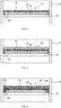
- FIG. 2 shows the same cross-sectional view of a chemical reactor as FIG. 1 with the difference that now catalyst particles 80 are arranged on the knitted fabric knitted fabric 50.
- the average clear mesh width of the knitted fabric knitted fabric 50 is in this case dimensioned so that the catalyst particles 80 are retained.
- FIG. 3 shows further embodiments of the in FIG. 1 and 2 previously described chemical reactor.
- additional knitted fabric mesh 60 inserted U-shaped.
- elastically prestressed knitted fabric knitted fabric 90 for example, a metallic sealing cord made of knit fabric, inserted.
- a layer of inert particles 100 is located between the layer of catalyst particles 80 and the knitted wire knit fabric 50.
- FIG. 4 shows one to the in FIG. 1 reactor shown analog device in which the lying on the support 30 knitted wire fabric 50 is formed continuously through to the reactor wall 10. Additional, round knit fabric knitted fabric 60 is arranged below it and seals the gap between the carrier 30 and reactor wall 10 also from.
- This embodiment has the advantage that the upper knit fabric layer 50 can be easily lifted for maintenance and inspection purposes.
- FIG. 5 corresponds to that in FIG. 5 , with the difference that analogous to FIG. 2 a layer of catalyst particles 80 has now been placed on the knitted fabric 50.
- FIG. 6 shows you one FIG. 3 analogous reactor, wherein on a layer of Inertpumblen 100, the catalyst particles 80 are arranged.
- the gap between the carrier 30 and the reactor wall 10 is sealed by the additional knitwear 60.
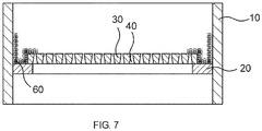
- This knitted fabric 60 is inserted in a U-shape, wherein the reactor wall 10 facing side of the "U” is vertical and the other side of the "U” follows the course of the shape of the support 30, that is, initially perpendicular and then horizontally further on the support 3 runs. Then the knitted wire fabric 50 is placed.
- FIG. 7 shows this course.
- This figure corresponds FIG. 6 wherein only the reactor walls 10, the support ring 20, supports 30, columns 40 and the additional knitwear 60 are shown.
- an elastically biased knitted fabric knitted fabric 90 are inserted.
- reaction product was cooled with water.
- the non-volatile constituents were condensed out and separated from the gaseous components in a downstream separator.
- the liquid components were led out of the separator into a product collection container and collected there.
- In front of the sump was a sampling point where samples of the product could be taken at regular intervals. These were analyzed by gas chromatography for the presence of nitrobenzene. If the nitrobenzene content in the crude product exceeded 500 ppm, the reaction was stopped and the catalyst was regenerated.
- the load was set to 1 g nitrobenzene / (ml of catalyst ⁇ h) and the hydrogen: nitrobenzene ratio to about 80: 1 in all examples.
- the catalyst was an alumina-supported metal catalyst containing 9 g / l support Pd, 9 g / l support V, 3 g / l support Pb on ⁇ -alumina (see EP 0 011 090 A1 ).
- the mean particle size x 50.3 of catalyst particles and, if necessary, inert particles was determined by sieve analysis.
- the reactor was in each case rendered inert with nitrogen and subjected to hydrogen at 240 ° C. over a period of 48 h. Then the nitrobenzene feed was started and increased over 5 hours to the above value.
- the reactor was in turn rendered inert with nitrogen, heated to 270 ° C and then subjected to air flow to burn off coke. This was carried out until no more heat emission could be detected and the CO 2 content in the exhaust gas stream had fallen to less than 0.2% (determined by IR photometry).
- test cycle the next cycle (hereafter referred to as the test cycle) recorded the time of the nitrobenzene breakthrough and cooled the reactor to ambient temperature after regeneration and opened for inspection.
- adiabatic hydrogenation of nitrobenzene to aniline was performed in a reactor equipped with a self-supporting column screen for the catalyst bed.
- the V-wire of the slotted screen had a width of 1.8 mm and a height of 3.7 mm, and the gap width between the V-shaped wires was 0.65 mm.
- the construction of the V-profile wires was normal, so not inverse.
- the slotted screen was made of parallel segments. Each segment lay on a support structure and was bolted to the next support. The connections protrude beyond the screen surface. Corrosion and bending of the profiles and support profiles were prevented by using austenitic steel.
- the outer support ring of the screen was floating on a bearing wall located on the reactor wall. In the cold state, there was a gap of approx. 1 cm between the support ring and the reactor wall.
- the fixed catalyst bed whose catalyst particles had a mean particle size x 50.3 of 1.5 mm, came to lie on the slotted screen.
- nitrobenzene having a concentration of more than 500 ppm was already found in the reaction product after a reaction time of 4 days.
- deep thrombi were detected in the catalyst bed. Below the thrombi, V-profile wires of the gap sieve had come off. Along the reactor wall, the catalyst bed also showed a depression.
- Example V-1 The experimental procedure corresponded to that of Example V-1, wherein in addition the support screen was covered with two 5 cm high layers of inert material.
- the first layer on the screen consisted of 6 mm diameter alumina spheres and the 4 mm diameter alumina spheres layer on top. Only on this second layer was the catalyst bed, whose catalyst particles had a mean particle size x 50.3 of 1.5 mm.
- nitrobenzene was found in the reaction product after a reaction time of about 36 days at a concentration of more than 500 ppm.
- a reaction time of about 36 days Upon inspection of the reactor, no thrombi were detected in the catalyst bed, although again damage to the support screen was observed. Along the reactor wall, the catalyst bed showed no depression. Neither catalyst nor inert material was found at the reactor bottom and in the subsequent apparatus.
- the test procedure corresponded to Comparative Example V-1, wherein additionally the slotted screen was covered with a knitted wire knit fabric of continuous wire.
- the knit fabric had a wire diameter of 0.23 mm, was knitted two times and folded in three layers.
- the knit fabric was made of stainless steel and the average mesh size was 0.65 mm.
- the knitwear was fastened to the split screen by means of bolts.
- the knit fabric was coated with a 5 cm high layer of inert alumina bead material having a mean particle size x 50.3 of 4 mm.
- the fixed catalyst bed whose catalyst particles had a mean particle size x 50.3 of 1.5 mm, came to rest on the inert material.
- Inventive example E-2 (gap sieve, wire mesh, inert material, met. Sealing cord, cat.)
- the experimental procedure corresponded to the example E-1, wherein additionally in the gap between the outer support ring of the slotted screen and the reactor wall, a metallic sealing cord made of knitted wire knitted fabric was inserted, the wire diameter was 0.23 mm and the average clear mesh width was 0.65 mm.
- the sealing cord was still flexible under the reaction conditions and had a diameter of 1.2 cm, so that it was attached by its own spring tension in the gap.
- Example E-3 (simple rust, wire mesh, metallic sealing cord, catalyst)
- adiabatic hydrogenation of nitrobenzene to aniline was performed in a reactor equipped with a simple grid for the catalyst bed.
- the average mesh size of the grate was 30 ⁇ 10 mm. Corrosion and bending of the profiles and support profiles were prevented by using austenitic steel.
- the outer support ring of the grate was floating on a bearing wall located on the reactor wall. It was a cold gap of about 1 cm between the support ring and reactor wall. In this gap, a metallic sealing cord made of knitted wire knit fabric was inserted, the wire diameter of 0.23 mm and the average clear mesh size was 0.65 mm. The sealing cord was still flexible under the reaction conditions and had a diameter of 1.2 cm, so that it was attached by its own spring tension in the gap.
- the grate was covered with a knitted wire knit fabric made of endless wire.
- the knit fabric had a wire diameter of 0.23 mm, was knitted two times and folded in three layers.
- the knit fabric was made of stainless steel and the average mesh size was 0.65 mm.
- the knitwear was fastened to the grate by means of bolts.
- the knits were covered with a 5 cm high layer of alumina ball inert material having a mean particle size x 50.3 of 4 mm.
- the fixed catalyst bed whose catalyst particles had a mean particle size x 50.3 of 1.5 mm, came to rest on the inert material.
- nitrobenzene with a concentration of more than 500 ppm was found in the reaction product after a reaction time of about 900 hours.
- the average clear mesh of the support grid was larger than the diameter of the catalyst or inert material particles.
- the catalyst bed showed no depression. Neither catalyst nor inert material was found at the reactor bottom and in the subsequent apparatus.
- Example E-4 (as Example E-3, but with increased catalyst bed)
- Example E-3 The experimental procedure corresponded to Example E-3 with the difference that the height of the catalyst bed was increased to 50 cm.
- the same amount of nitrobenzene was reacted per unit time as in Comparative Examples and Examples E-1 to E-3.
Landscapes
- Chemical & Material Sciences (AREA)
- Organic Chemistry (AREA)
- Chemical Kinetics & Catalysis (AREA)
- Engineering & Computer Science (AREA)
- Physics & Mathematics (AREA)
- Combustion & Propulsion (AREA)
- Fluid Mechanics (AREA)
- Textile Engineering (AREA)
- Organic Low-Molecular-Weight Compounds And Preparation Thereof (AREA)
- Low-Molecular Organic Synthesis Reactions Using Catalysts (AREA)
- Devices And Processes Conducted In The Presence Of Fluids And Solid Particles (AREA)
- Physical Or Chemical Processes And Apparatus (AREA)
- Catalysts (AREA)
Applications Claiming Priority (2)
| Application Number | Priority Date | Filing Date | Title |
|---|---|---|---|
| DE102010044111 | 2010-11-18 | ||
| PCT/EP2011/070101 WO2012065969A1 (de) | 2010-11-18 | 2011-11-15 | Chemischer reaktor mit drahtgestrick-maschenware als halteeinrichtung für partikel |
Publications (2)
| Publication Number | Publication Date |
|---|---|
| EP2640504A1 EP2640504A1 (de) | 2013-09-25 |
| EP2640504B1 true EP2640504B1 (de) | 2018-05-09 |
Family
ID=45001735
Family Applications (1)
| Application Number | Title | Priority Date | Filing Date |
|---|---|---|---|
| EP11785384.6A Active EP2640504B1 (de) | 2010-11-18 | 2011-11-15 | Chemischer reaktor mit drahtgestrick-maschenware als halteeinrichtung für partikel |
Country Status (11)
| Country | Link |
|---|---|
| US (1) | US9364810B2 (enExample) |
| EP (1) | EP2640504B1 (enExample) |
| JP (1) | JP6073236B2 (enExample) |
| KR (1) | KR101854486B1 (enExample) |
| CN (2) | CN103313781B (enExample) |
| BR (1) | BR112013012318A2 (enExample) |
| MX (1) | MX2013005523A (enExample) |
| PT (1) | PT2640504T (enExample) |
| RU (1) | RU2579392C2 (enExample) |
| SG (1) | SG190303A1 (enExample) |
| WO (1) | WO2012065969A1 (enExample) |
Families Citing this family (15)
| Publication number | Priority date | Publication date | Assignee | Title |
|---|---|---|---|---|
| DE102014223813A1 (de) | 2014-11-21 | 2016-05-25 | Thyssenkrupp Ag | Brennerkorb für einen Ammoniak-Oxidationsbrenner |
| RU2020108186A (ru) * | 2017-07-27 | 2021-08-27 | Хальдор Топсёэ А/С | Каталитический реактор, содержащий волокнистую подложку частиц катализатора |
| US11298669B2 (en) | 2017-12-21 | 2022-04-12 | Uop Llc | Scale collection device for downflow reactors |
| US10537866B2 (en) * | 2017-12-21 | 2020-01-21 | Uop Llc | Scale collection device for downflow reactors |
| US10549249B2 (en) | 2017-12-21 | 2020-02-04 | Uop Llc | Scale collection device for downflow reactors |
| US10556212B2 (en) | 2017-12-21 | 2020-02-11 | Uop Llc | Scale collection device for downflow reactors |
| US11224849B2 (en) | 2017-12-21 | 2022-01-18 | Uop Llc | Scale collection device for downflow reactors |
| US10576439B2 (en) | 2017-12-21 | 2020-03-03 | Uop Llc | Scale collection device for downflow reactors |
| FR3083717B1 (fr) * | 2018-07-11 | 2020-06-26 | L'air Liquide, Societe Anonyme Pour L'etude Et L'exploitation Des Procedes Georges Claude | Dispositif permettant de limiter ou supprimer la migration de particules entre deux couches |
| FR3083718B1 (fr) * | 2018-07-11 | 2020-07-03 | L'air Liquide, Societe Anonyme Pour L'etude Et L'exploitation Des Procedes Georges Claude | Dispositif en toile permettant de limiter ou supprimer la migration de particules entre deux couches |
| DE102021201811A1 (de) | 2020-02-25 | 2021-08-26 | Thyssenkrupp Ag | Reaktor für die katalytische Behandlung eines Gasstroms |
| BE1027663B1 (de) * | 2020-02-25 | 2021-05-06 | Thyssenkrupp Ind Solutions Ag | Reaktor für die katalytische Behandlung eines Gasstroms |
| WO2021170756A1 (de) | 2020-02-25 | 2021-09-02 | Thyssenkrupp Industrial Solutions Ag | Reaktor für die katalytische behandlung eines gasstroms |
| CN113713584A (zh) * | 2021-09-10 | 2021-11-30 | 南京尚中过滤与分析设备有限公司 | 一种去除烟气中so2的装置和方法 |
| CN116712968B (zh) * | 2023-05-06 | 2025-08-15 | 中国石油化工股份有限公司 | 一种固定床反应器用催化剂格栅及固定床反应器 |
Citations (1)
| Publication number | Priority date | Publication date | Assignee | Title |
|---|---|---|---|---|
| EP2327473A1 (en) * | 2008-08-05 | 2011-06-01 | Freund Corporation | Fluidized bed device |
Family Cites Families (22)
| Publication number | Priority date | Publication date | Assignee | Title |
|---|---|---|---|---|
| US2283499A (en) * | 1939-11-07 | 1942-05-19 | Phillips Petroleum Co | Catalytic process |
| US2915375A (en) | 1955-10-17 | 1959-12-01 | Houdry Process Corp | Reactor for hydrocarbon conversions |
| DE2849002A1 (de) | 1978-11-11 | 1980-05-22 | Bayer Ag | Verfahren zur katalytischen hydrierung von nitrobenzol |
| ATE73010T1 (de) * | 1988-10-12 | 1992-03-15 | Johnson Matthey Plc | Metallgewebe. |
| JPH04141227A (ja) * | 1990-10-03 | 1992-05-14 | Nagaoka Kinmo Kk | ラジアルフロー式触媒充填塔における触媒保持方法および装置 |
| FR2684893A1 (fr) * | 1991-12-16 | 1993-06-18 | Inst Francais Du Petrole | Procede de distillation reactive catalytique et appareillage pour sa mise en óoeuvre. |
| US5348710A (en) * | 1993-06-11 | 1994-09-20 | Johnson Kenneth H | Catalytic distillation structure |
| AU1372895A (en) * | 1994-06-17 | 1996-01-15 | Chevron U.S.A. Inc. | Catalyst support and process for its use |
| DE4428018A1 (de) | 1994-08-08 | 1996-02-15 | Bayer Ag | Verfahren zur Herstellung von aromatischen Aminen |
| DE4428017A1 (de) * | 1994-08-08 | 1996-02-15 | Bayer Ag | Verfahren zur Herstellung von aromatischen Aminen |
| DE19706434A1 (de) * | 1997-02-19 | 1998-08-20 | Glatt Ingtech Gmbh | Anströmboden für Wirbelschicht-Prozeßanlagen |
| US20020068026A1 (en) * | 1997-08-08 | 2002-06-06 | Lawrence L. Murrell | Reactor |
| DE19827375A1 (de) * | 1998-06-19 | 1999-12-23 | Bosch Gmbh Robert | Vorrichtung zum Messen der Masse eines strömenden Mediums |
| WO2002070120A1 (en) | 2001-03-01 | 2002-09-12 | Shell Internationale Research Maatschappij B.V. | Self-supporting reactor internal |
| WO2003050854A2 (en) * | 2001-12-12 | 2003-06-19 | The Pennsylvania State University | Chemical reactor templates: sacrificial layer fabrication and template use |
| US20040000472A1 (en) * | 2002-03-15 | 2004-01-01 | Catalytic Distillation Technologies | Distillation system |
| AU2002253451B1 (en) * | 2002-04-16 | 2003-10-27 | African Oxygen Limited | Chemical bed design |
| JP2004135689A (ja) * | 2002-10-15 | 2004-05-13 | Kanagawa Prefecture | 光触媒を用いたガス除去用フィルタ及びその製造方法 |
| CN1241667C (zh) * | 2003-07-14 | 2006-02-15 | 中国石油化工股份有限公司 | 一种催化蒸馏组件及使用该组件的催化蒸馏方法 |
| BRPI0418085A (pt) * | 2003-12-23 | 2007-04-17 | Basf Ag | processos para preparar (met) acroleìna e/ou ácido (met)acrìlico, e para incorporar um dispositivo |
| DE102005019540A1 (de) * | 2005-04-27 | 2006-11-09 | Basf Ag | Verfahren zur Herstellung eines Amins |
| DE102008010422A1 (de) * | 2008-02-21 | 2009-09-03 | Uhde Gmbh | Fixiervorrichtung für Katalysatorpartikel |
-
2011
- 2011-11-15 BR BR112013012318A patent/BR112013012318A2/pt not_active IP Right Cessation
- 2011-11-15 KR KR1020137015605A patent/KR101854486B1/ko not_active Expired - Fee Related
- 2011-11-15 MX MX2013005523A patent/MX2013005523A/es active IP Right Grant
- 2011-11-15 SG SG2013037650A patent/SG190303A1/en unknown
- 2011-11-15 US US13/988,326 patent/US9364810B2/en active Active
- 2011-11-15 EP EP11785384.6A patent/EP2640504B1/de active Active
- 2011-11-15 WO PCT/EP2011/070101 patent/WO2012065969A1/de not_active Ceased
- 2011-11-15 JP JP2013539224A patent/JP6073236B2/ja active Active
- 2011-11-15 CN CN201180065414.7A patent/CN103313781B/zh not_active Expired - Fee Related
- 2011-11-15 PT PT117853846T patent/PT2640504T/pt unknown
- 2011-11-15 RU RU2013127397/05A patent/RU2579392C2/ru not_active IP Right Cessation
- 2011-11-15 CN CN201611089359.6A patent/CN106378064B/zh active Active
Patent Citations (1)
| Publication number | Priority date | Publication date | Assignee | Title |
|---|---|---|---|---|
| EP2327473A1 (en) * | 2008-08-05 | 2011-06-01 | Freund Corporation | Fluidized bed device |
Also Published As
| Publication number | Publication date |
|---|---|
| CN106378064B (zh) | 2020-04-28 |
| JP6073236B2 (ja) | 2017-02-01 |
| EP2640504A1 (de) | 2013-09-25 |
| JP2014503342A (ja) | 2014-02-13 |
| WO2012065969A1 (de) | 2012-05-24 |
| US9364810B2 (en) | 2016-06-14 |
| BR112013012318A2 (pt) | 2016-08-16 |
| RU2013127397A (ru) | 2014-12-27 |
| US20130296610A1 (en) | 2013-11-07 |
| CN103313781A (zh) | 2013-09-18 |
| KR101854486B1 (ko) | 2018-05-03 |
| KR20130121868A (ko) | 2013-11-06 |
| RU2579392C2 (ru) | 2016-04-10 |
| CN103313781B (zh) | 2016-12-07 |
| CN106378064A (zh) | 2017-02-08 |
| SG190303A1 (en) | 2013-06-28 |
| MX2013005523A (es) | 2013-07-05 |
| PT2640504T (pt) | 2018-09-28 |
Similar Documents
| Publication | Publication Date | Title |
|---|---|---|
| EP2640504B1 (de) | Chemischer reaktor mit drahtgestrick-maschenware als halteeinrichtung für partikel | |
| EP0402783B1 (de) | Reaktor | |
| EP2689841B1 (de) | Katalysator | |
| EP0396650A1 (de) | Vorrichtung zur durchführung katalysierter reaktionen. | |
| DE69833430T2 (de) | Vorrichtung zur abwasserbehandlung | |
| WO2003072237A1 (de) | Reaktor und verfahren zur herstellung von phosgen | |
| WO2020148143A1 (de) | Katalysatorsystem sowie verfahren zur katalytischen verbrennung von ammoniak zu stickstoffoxiden in einer mitteldruckanlage | |
| DE60201502T2 (de) | Dreidimensionale, in zwei oder mehreren schichten gestrickte katalysatornetze | |
| WO2020148144A1 (de) | Katalysatorsystem sowie verfahren zur katalytischen verbrennung von ammoniak zu stickstoffoxiden in einer mitteldruckanlage | |
| DE102004061770A1 (de) | Verfahren zur Herstellung von Phthalsäureanhydrid | |
| EP4031699B1 (de) | Verfahren zum stricken von edelmetallnetzen | |
| EP2246320A1 (de) | Verfahren zur Herstellung von aromatischen Aminen | |
| EP4100364B1 (de) | Verfahren und reaktor zur herstellung von phosgen | |
| EP4247554B1 (de) | Edelmetallnetz für die katalysierung von gasphasenreaktionen | |
| DE10159816A1 (de) | Vorrichtung und Verfahren zur Durchführung von heterogen katalysierten Reaktionen | |
| EP2753576B1 (de) | Vorrichtung zur bypass-minderung in ammoniak-oxidationsbrennern | |
| EP4110728B1 (de) | Reaktor für die katalytische behandlung eines gasstroms | |
| BE1027663B1 (de) | Reaktor für die katalytische Behandlung eines Gasstroms | |
| WO2025119510A1 (de) | Katalysatorsystem für einen strömungsreaktor sowie verfahren zur katalytischen oxidation von ammoniak | |
| EP4344773A1 (de) | Katalysatorsystem mit einem katalysatornetz umfassend einen edelmetalldraht für lange kampagnen in der ammoniakoxidation | |
| DE102021201811A1 (de) | Reaktor für die katalytische Behandlung eines Gasstroms | |
| DE19911094B4 (de) | Reaktor zur Durchführung katalytischer Reaktionen | |
| EP4606469A1 (de) | Segmentierte haltevorrichtung für schüttgutkörper | |
| EP4282527A1 (de) | Katalysatorsystem für einen strömungsreaktor sowie verfahren zur katalytischen oxidation von ammoniak | |
| DE102007032019A1 (de) | Reaktor |
Legal Events
| Date | Code | Title | Description |
|---|---|---|---|
| PUAI | Public reference made under article 153(3) epc to a published international application that has entered the european phase |
Free format text: ORIGINAL CODE: 0009012 |
|
| 17P | Request for examination filed |
Effective date: 20130618 |
|
| AK | Designated contracting states |
Kind code of ref document: A1 Designated state(s): AL AT BE BG CH CY CZ DE DK EE ES FI FR GB GR HR HU IE IS IT LI LT LU LV MC MK MT NL NO PL PT RO RS SE SI SK SM TR |
|
| DAX | Request for extension of the european patent (deleted) | ||
| RAP1 | Party data changed (applicant data changed or rights of an application transferred) |
Owner name: COVESTRO DEUTSCHLAND AG |
|
| 17Q | First examination report despatched |
Effective date: 20160323 |
|
| GRAP | Despatch of communication of intention to grant a patent |
Free format text: ORIGINAL CODE: EPIDOSNIGR1 |
|
| GRAJ | Information related to disapproval of communication of intention to grant by the applicant or resumption of examination proceedings by the epo deleted |
Free format text: ORIGINAL CODE: EPIDOSDIGR1 |
|
| INTG | Intention to grant announced |
Effective date: 20170920 |
|
| INTC | Intention to grant announced (deleted) | ||
| GRAP | Despatch of communication of intention to grant a patent |
Free format text: ORIGINAL CODE: EPIDOSNIGR1 |
|
| INTG | Intention to grant announced |
Effective date: 20171205 |
|
| GRAS | Grant fee paid |
Free format text: ORIGINAL CODE: EPIDOSNIGR3 |
|
| GRAA | (expected) grant |
Free format text: ORIGINAL CODE: 0009210 |
|
| AK | Designated contracting states |
Kind code of ref document: B1 Designated state(s): AL AT BE BG CH CY CZ DE DK EE ES FI FR GB GR HR HU IE IS IT LI LT LU LV MC MK MT NL NO PL PT RO RS SE SI SK SM TR |
|
| REG | Reference to a national code |
Ref country code: GB Ref legal event code: FG4D Free format text: NOT ENGLISH |
|
| REG | Reference to a national code |
Ref country code: CH Ref legal event code: EP Ref country code: AT Ref legal event code: REF Ref document number: 997075 Country of ref document: AT Kind code of ref document: T Effective date: 20180515 |
|
| REG | Reference to a national code |
Ref country code: DE Ref legal event code: R096 Ref document number: 502011014168 Country of ref document: DE Ref country code: IE Ref legal event code: FG4D Free format text: LANGUAGE OF EP DOCUMENT: GERMAN |
|
| REG | Reference to a national code |
Ref country code: NL Ref legal event code: MP Effective date: 20180509 |
|
| REG | Reference to a national code |
Ref country code: LT Ref legal event code: MG4D |
|
| REG | Reference to a national code |
Ref country code: PT Ref legal event code: SC4A Ref document number: 2640504 Country of ref document: PT Date of ref document: 20180928 Kind code of ref document: T Free format text: AVAILABILITY OF NATIONAL TRANSLATION Effective date: 20180807 |
|
| PG25 | Lapsed in a contracting state [announced via postgrant information from national office to epo] |
Ref country code: FI Free format text: LAPSE BECAUSE OF FAILURE TO SUBMIT A TRANSLATION OF THE DESCRIPTION OR TO PAY THE FEE WITHIN THE PRESCRIBED TIME-LIMIT Effective date: 20180509 Ref country code: LT Free format text: LAPSE BECAUSE OF FAILURE TO SUBMIT A TRANSLATION OF THE DESCRIPTION OR TO PAY THE FEE WITHIN THE PRESCRIBED TIME-LIMIT Effective date: 20180509 Ref country code: BG Free format text: LAPSE BECAUSE OF FAILURE TO SUBMIT A TRANSLATION OF THE DESCRIPTION OR TO PAY THE FEE WITHIN THE PRESCRIBED TIME-LIMIT Effective date: 20180809 Ref country code: ES Free format text: LAPSE BECAUSE OF FAILURE TO SUBMIT A TRANSLATION OF THE DESCRIPTION OR TO PAY THE FEE WITHIN THE PRESCRIBED TIME-LIMIT Effective date: 20180509 Ref country code: NO Free format text: LAPSE BECAUSE OF FAILURE TO SUBMIT A TRANSLATION OF THE DESCRIPTION OR TO PAY THE FEE WITHIN THE PRESCRIBED TIME-LIMIT Effective date: 20180809 Ref country code: SE Free format text: LAPSE BECAUSE OF FAILURE TO SUBMIT A TRANSLATION OF THE DESCRIPTION OR TO PAY THE FEE WITHIN THE PRESCRIBED TIME-LIMIT Effective date: 20180509 |
|
| PG25 | Lapsed in a contracting state [announced via postgrant information from national office to epo] |
Ref country code: GR Free format text: LAPSE BECAUSE OF FAILURE TO SUBMIT A TRANSLATION OF THE DESCRIPTION OR TO PAY THE FEE WITHIN THE PRESCRIBED TIME-LIMIT Effective date: 20180810 Ref country code: RS Free format text: LAPSE BECAUSE OF FAILURE TO SUBMIT A TRANSLATION OF THE DESCRIPTION OR TO PAY THE FEE WITHIN THE PRESCRIBED TIME-LIMIT Effective date: 20180509 Ref country code: LV Free format text: LAPSE BECAUSE OF FAILURE TO SUBMIT A TRANSLATION OF THE DESCRIPTION OR TO PAY THE FEE WITHIN THE PRESCRIBED TIME-LIMIT Effective date: 20180509 Ref country code: HR Free format text: LAPSE BECAUSE OF FAILURE TO SUBMIT A TRANSLATION OF THE DESCRIPTION OR TO PAY THE FEE WITHIN THE PRESCRIBED TIME-LIMIT Effective date: 20180509 Ref country code: NL Free format text: LAPSE BECAUSE OF FAILURE TO SUBMIT A TRANSLATION OF THE DESCRIPTION OR TO PAY THE FEE WITHIN THE PRESCRIBED TIME-LIMIT Effective date: 20180509 |
|
| PG25 | Lapsed in a contracting state [announced via postgrant information from national office to epo] |
Ref country code: DK Free format text: LAPSE BECAUSE OF FAILURE TO SUBMIT A TRANSLATION OF THE DESCRIPTION OR TO PAY THE FEE WITHIN THE PRESCRIBED TIME-LIMIT Effective date: 20180509 Ref country code: PL Free format text: LAPSE BECAUSE OF FAILURE TO SUBMIT A TRANSLATION OF THE DESCRIPTION OR TO PAY THE FEE WITHIN THE PRESCRIBED TIME-LIMIT Effective date: 20180509 Ref country code: RO Free format text: LAPSE BECAUSE OF FAILURE TO SUBMIT A TRANSLATION OF THE DESCRIPTION OR TO PAY THE FEE WITHIN THE PRESCRIBED TIME-LIMIT Effective date: 20180509 Ref country code: SK Free format text: LAPSE BECAUSE OF FAILURE TO SUBMIT A TRANSLATION OF THE DESCRIPTION OR TO PAY THE FEE WITHIN THE PRESCRIBED TIME-LIMIT Effective date: 20180509 Ref country code: EE Free format text: LAPSE BECAUSE OF FAILURE TO SUBMIT A TRANSLATION OF THE DESCRIPTION OR TO PAY THE FEE WITHIN THE PRESCRIBED TIME-LIMIT Effective date: 20180509 |
|
| REG | Reference to a national code |
Ref country code: DE Ref legal event code: R097 Ref document number: 502011014168 Country of ref document: DE |
|
| PG25 | Lapsed in a contracting state [announced via postgrant information from national office to epo] |
Ref country code: IT Free format text: LAPSE BECAUSE OF FAILURE TO SUBMIT A TRANSLATION OF THE DESCRIPTION OR TO PAY THE FEE WITHIN THE PRESCRIBED TIME-LIMIT Effective date: 20180509 Ref country code: SM Free format text: LAPSE BECAUSE OF FAILURE TO SUBMIT A TRANSLATION OF THE DESCRIPTION OR TO PAY THE FEE WITHIN THE PRESCRIBED TIME-LIMIT Effective date: 20180509 |
|
| PLBE | No opposition filed within time limit |
Free format text: ORIGINAL CODE: 0009261 |
|
| STAA | Information on the status of an ep patent application or granted ep patent |
Free format text: STATUS: NO OPPOSITION FILED WITHIN TIME LIMIT |
|
| 26N | No opposition filed |
Effective date: 20190212 |
|
| PG25 | Lapsed in a contracting state [announced via postgrant information from national office to epo] |
Ref country code: SI Free format text: LAPSE BECAUSE OF FAILURE TO SUBMIT A TRANSLATION OF THE DESCRIPTION OR TO PAY THE FEE WITHIN THE PRESCRIBED TIME-LIMIT Effective date: 20180509 |
|
| REG | Reference to a national code |
Ref country code: CH Ref legal event code: PL |
|
| PG25 | Lapsed in a contracting state [announced via postgrant information from national office to epo] |
Ref country code: MC Free format text: LAPSE BECAUSE OF FAILURE TO SUBMIT A TRANSLATION OF THE DESCRIPTION OR TO PAY THE FEE WITHIN THE PRESCRIBED TIME-LIMIT Effective date: 20180509 Ref country code: LU Free format text: LAPSE BECAUSE OF NON-PAYMENT OF DUE FEES Effective date: 20181115 |
|
| REG | Reference to a national code |
Ref country code: IE Ref legal event code: MM4A |
|
| PG25 | Lapsed in a contracting state [announced via postgrant information from national office to epo] |
Ref country code: CH Free format text: LAPSE BECAUSE OF NON-PAYMENT OF DUE FEES Effective date: 20181130 Ref country code: LI Free format text: LAPSE BECAUSE OF NON-PAYMENT OF DUE FEES Effective date: 20181130 |
|
| PG25 | Lapsed in a contracting state [announced via postgrant information from national office to epo] |
Ref country code: FR Free format text: LAPSE BECAUSE OF NON-PAYMENT OF DUE FEES Effective date: 20181130 Ref country code: IE Free format text: LAPSE BECAUSE OF NON-PAYMENT OF DUE FEES Effective date: 20181115 |
|
| PG25 | Lapsed in a contracting state [announced via postgrant information from national office to epo] |
Ref country code: AL Free format text: LAPSE BECAUSE OF FAILURE TO SUBMIT A TRANSLATION OF THE DESCRIPTION OR TO PAY THE FEE WITHIN THE PRESCRIBED TIME-LIMIT Effective date: 20180509 |
|
| REG | Reference to a national code |
Ref country code: AT Ref legal event code: MM01 Ref document number: 997075 Country of ref document: AT Kind code of ref document: T Effective date: 20181115 |
|
| PG25 | Lapsed in a contracting state [announced via postgrant information from national office to epo] |
Ref country code: AT Free format text: LAPSE BECAUSE OF NON-PAYMENT OF DUE FEES Effective date: 20181115 Ref country code: MT Free format text: LAPSE BECAUSE OF FAILURE TO SUBMIT A TRANSLATION OF THE DESCRIPTION OR TO PAY THE FEE WITHIN THE PRESCRIBED TIME-LIMIT Effective date: 20180509 |
|
| PG25 | Lapsed in a contracting state [announced via postgrant information from national office to epo] |
Ref country code: TR Free format text: LAPSE BECAUSE OF FAILURE TO SUBMIT A TRANSLATION OF THE DESCRIPTION OR TO PAY THE FEE WITHIN THE PRESCRIBED TIME-LIMIT Effective date: 20180509 |
|
| PG25 | Lapsed in a contracting state [announced via postgrant information from national office to epo] |
Ref country code: HU Free format text: LAPSE BECAUSE OF FAILURE TO SUBMIT A TRANSLATION OF THE DESCRIPTION OR TO PAY THE FEE WITHIN THE PRESCRIBED TIME-LIMIT; INVALID AB INITIO Effective date: 20111115 Ref country code: CY Free format text: LAPSE BECAUSE OF FAILURE TO SUBMIT A TRANSLATION OF THE DESCRIPTION OR TO PAY THE FEE WITHIN THE PRESCRIBED TIME-LIMIT Effective date: 20180509 Ref country code: MK Free format text: LAPSE BECAUSE OF NON-PAYMENT OF DUE FEES Effective date: 20180509 |
|
| PG25 | Lapsed in a contracting state [announced via postgrant information from national office to epo] |
Ref country code: IS Free format text: LAPSE BECAUSE OF FAILURE TO SUBMIT A TRANSLATION OF THE DESCRIPTION OR TO PAY THE FEE WITHIN THE PRESCRIBED TIME-LIMIT Effective date: 20180909 |
|
| PGFP | Annual fee paid to national office [announced via postgrant information from national office to epo] |
Ref country code: PT Payment date: 20221104 Year of fee payment: 12 Ref country code: GB Payment date: 20221020 Year of fee payment: 12 Ref country code: DE Payment date: 20220621 Year of fee payment: 12 |
|
| REG | Reference to a national code |
Ref country code: DE Ref legal event code: R119 Ref document number: 502011014168 Country of ref document: DE |
|
| GBPC | Gb: european patent ceased through non-payment of renewal fee |
Effective date: 20231115 |
|
| PG25 | Lapsed in a contracting state [announced via postgrant information from national office to epo] |
Ref country code: PT Free format text: LAPSE BECAUSE OF NON-PAYMENT OF DUE FEES Effective date: 20240515 |
|
| PG25 | Lapsed in a contracting state [announced via postgrant information from national office to epo] |
Ref country code: PT Free format text: LAPSE BECAUSE OF NON-PAYMENT OF DUE FEES Effective date: 20240515 |
|
| PG25 | Lapsed in a contracting state [announced via postgrant information from national office to epo] |
Ref country code: DE Free format text: LAPSE BECAUSE OF NON-PAYMENT OF DUE FEES Effective date: 20240601 |
|
| PG25 | Lapsed in a contracting state [announced via postgrant information from national office to epo] |
Ref country code: GB Free format text: LAPSE BECAUSE OF NON-PAYMENT OF DUE FEES Effective date: 20231115 |
|
| PG25 | Lapsed in a contracting state [announced via postgrant information from national office to epo] |
Ref country code: GB Free format text: LAPSE BECAUSE OF NON-PAYMENT OF DUE FEES Effective date: 20231115 Ref country code: DE Free format text: LAPSE BECAUSE OF NON-PAYMENT OF DUE FEES Effective date: 20240601 |
|
| PGFP | Annual fee paid to national office [announced via postgrant information from national office to epo] |
Ref country code: BE Payment date: 20241027 Year of fee payment: 14 |
|
| PGFP | Annual fee paid to national office [announced via postgrant information from national office to epo] |
Ref country code: CZ Payment date: 20241030 Year of fee payment: 14 |