EP2640504B1 - Chemical reactor with knitted wire mesh fabric as a holding device for particles - Google Patents
Chemical reactor with knitted wire mesh fabric as a holding device for particles Download PDFInfo
- Publication number
- EP2640504B1 EP2640504B1 EP11785384.6A EP11785384A EP2640504B1 EP 2640504 B1 EP2640504 B1 EP 2640504B1 EP 11785384 A EP11785384 A EP 11785384A EP 2640504 B1 EP2640504 B1 EP 2640504B1
- Authority
- EP
- European Patent Office
- Prior art keywords
- reactor
- particles
- knitted fabric
- wire mesh
- catalyst
- Prior art date
- Legal status (The legal status is an assumption and is not a legal conclusion. Google has not performed a legal analysis and makes no representation as to the accuracy of the status listed.)
- Active
Links
- 239000002245 particle Substances 0.000 title claims description 109
- 239000004744 fabric Substances 0.000 title claims description 86
- 239000000126 substance Substances 0.000 title claims description 17
- 239000003054 catalyst Substances 0.000 claims description 97
- 239000012530 fluid Substances 0.000 claims description 28
- 238000006243 chemical reaction Methods 0.000 claims description 22
- 238000000034 method Methods 0.000 claims description 17
- UFHFLCQGNIYNRP-UHFFFAOYSA-N Hydrogen Chemical compound [H][H] UFHFLCQGNIYNRP-UHFFFAOYSA-N 0.000 claims description 6
- 239000001257 hydrogen Substances 0.000 claims description 6
- 229910052739 hydrogen Inorganic materials 0.000 claims description 6
- 238000011144 upstream manufacturing Methods 0.000 claims description 4
- -1 aromatic nitro compounds Chemical class 0.000 claims description 3
- 238000006555 catalytic reaction Methods 0.000 claims description 3
- 230000009471 action Effects 0.000 claims description 2
- QVGXLLKOCUKJST-UHFFFAOYSA-N atomic oxygen Chemical compound [O] QVGXLLKOCUKJST-UHFFFAOYSA-N 0.000 claims description 2
- 239000002638 heterogeneous catalyst Substances 0.000 claims description 2
- 239000001301 oxygen Substances 0.000 claims description 2
- 229910052760 oxygen Inorganic materials 0.000 claims description 2
- LQNUZADURLCDLV-UHFFFAOYSA-N nitrobenzene Chemical compound [O-][N+](=O)C1=CC=CC=C1 LQNUZADURLCDLV-UHFFFAOYSA-N 0.000 description 53
- 239000000463 material Substances 0.000 description 26
- PAYRUJLWNCNPSJ-UHFFFAOYSA-N Aniline Chemical compound NC1=CC=CC=C1 PAYRUJLWNCNPSJ-UHFFFAOYSA-N 0.000 description 13
- 238000007789 sealing Methods 0.000 description 12
- 238000012360 testing method Methods 0.000 description 11
- 239000007795 chemical reaction product Substances 0.000 description 8
- 238000005984 hydrogenation reaction Methods 0.000 description 8
- 238000007689 inspection Methods 0.000 description 8
- 238000009940 knitting Methods 0.000 description 7
- 238000004519 manufacturing process Methods 0.000 description 7
- 238000005029 sieve analysis Methods 0.000 description 7
- PNEYBMLMFCGWSK-UHFFFAOYSA-N aluminium oxide Inorganic materials [O-2].[O-2].[O-2].[Al+3].[Al+3] PNEYBMLMFCGWSK-UHFFFAOYSA-N 0.000 description 6
- 230000000737 periodic effect Effects 0.000 description 6
- 230000035484 reaction time Effects 0.000 description 6
- 230000008569 process Effects 0.000 description 5
- 238000012216 screening Methods 0.000 description 5
- IJGRMHOSHXDMSA-UHFFFAOYSA-N Atomic nitrogen Chemical compound N#N IJGRMHOSHXDMSA-UHFFFAOYSA-N 0.000 description 4
- 230000008901 benefit Effects 0.000 description 4
- 230000000052 comparative effect Effects 0.000 description 4
- 238000007667 floating Methods 0.000 description 4
- 238000012423 maintenance Methods 0.000 description 4
- 229910052751 metal Inorganic materials 0.000 description 4
- 239000002184 metal Substances 0.000 description 4
- 230000008929 regeneration Effects 0.000 description 4
- 238000011069 regeneration method Methods 0.000 description 4
- 229910001220 stainless steel Inorganic materials 0.000 description 4
- 229910000831 Steel Inorganic materials 0.000 description 3
- 230000001186 cumulative effect Effects 0.000 description 3
- 238000002474 experimental method Methods 0.000 description 3
- 239000007789 gas Substances 0.000 description 3
- 239000012495 reaction gas Substances 0.000 description 3
- 239000010935 stainless steel Substances 0.000 description 3
- 239000010959 steel Substances 0.000 description 3
- 230000008646 thermal stress Effects 0.000 description 3
- 238000005452 bending Methods 0.000 description 2
- 230000006835 compression Effects 0.000 description 2
- 238000007906 compression Methods 0.000 description 2
- 238000010276 construction Methods 0.000 description 2
- 230000007797 corrosion Effects 0.000 description 2
- 238000005260 corrosion Methods 0.000 description 2
- 230000007547 defect Effects 0.000 description 2
- 238000005516 engineering process Methods 0.000 description 2
- JEIPFZHSYJVQDO-UHFFFAOYSA-N iron(III) oxide Inorganic materials O=[Fe]O[Fe]=O JEIPFZHSYJVQDO-UHFFFAOYSA-N 0.000 description 2
- 239000007788 liquid Substances 0.000 description 2
- 230000014759 maintenance of location Effects 0.000 description 2
- 229910052757 nitrogen Inorganic materials 0.000 description 2
- TWNQGVIAIRXVLR-UHFFFAOYSA-N oxo(oxoalumanyloxy)alumane Chemical compound O=[Al]O[Al]=O TWNQGVIAIRXVLR-UHFFFAOYSA-N 0.000 description 2
- 239000000047 product Substances 0.000 description 2
- 239000000376 reactant Substances 0.000 description 2
- 230000000717 retained effect Effects 0.000 description 2
- 238000007873 sieving Methods 0.000 description 2
- 230000035882 stress Effects 0.000 description 2
- OKTJSMMVPCPJKN-UHFFFAOYSA-N Carbon Chemical compound [C] OKTJSMMVPCPJKN-UHFFFAOYSA-N 0.000 description 1
- RYGMFSIKBFXOCR-UHFFFAOYSA-N Copper Chemical compound [Cu] RYGMFSIKBFXOCR-UHFFFAOYSA-N 0.000 description 1
- 229910000792 Monel Inorganic materials 0.000 description 1
- 208000007536 Thrombosis Diseases 0.000 description 1
- 229910052782 aluminium Inorganic materials 0.000 description 1
- XAGFODPZIPBFFR-UHFFFAOYSA-N aluminium Chemical compound [Al] XAGFODPZIPBFFR-UHFFFAOYSA-N 0.000 description 1
- 150000001412 amines Chemical class 0.000 description 1
- 239000011324 bead Substances 0.000 description 1
- 229910052799 carbon Inorganic materials 0.000 description 1
- 239000000969 carrier Substances 0.000 description 1
- 230000015556 catabolic process Effects 0.000 description 1
- 239000000571 coke Substances 0.000 description 1
- 239000000470 constituent Substances 0.000 description 1
- 229910052802 copper Inorganic materials 0.000 description 1
- 239000010949 copper Substances 0.000 description 1
- 239000012043 crude product Substances 0.000 description 1
- 238000013461 design Methods 0.000 description 1
- 239000000428 dust Substances 0.000 description 1
- 230000007613 environmental effect Effects 0.000 description 1
- 238000011156 evaluation Methods 0.000 description 1
- 230000002349 favourable effect Effects 0.000 description 1
- 239000012634 fragment Substances 0.000 description 1
- 238000004817 gas chromatography Methods 0.000 description 1
- 238000007210 heterogeneous catalysis Methods 0.000 description 1
- 238000003780 insertion Methods 0.000 description 1
- 230000037431 insertion Effects 0.000 description 1
- 230000002045 lasting effect Effects 0.000 description 1
- 238000010327 methods by industry Methods 0.000 description 1
- 239000000203 mixture Substances 0.000 description 1
- 229910000510 noble metal Inorganic materials 0.000 description 1
- 238000003921 particle size analysis Methods 0.000 description 1
- 238000005375 photometry Methods 0.000 description 1
- 238000012545 processing Methods 0.000 description 1
- 230000008439 repair process Effects 0.000 description 1
- 238000005070 sampling Methods 0.000 description 1
- 210000002023 somite Anatomy 0.000 description 1
- 238000001228 spectrum Methods 0.000 description 1
- 238000010998 test method Methods 0.000 description 1
- 239000004753 textile Substances 0.000 description 1
- 229910052723 transition metal Inorganic materials 0.000 description 1
- 150000003624 transition metals Chemical class 0.000 description 1
- XLYOFNOQVPJJNP-UHFFFAOYSA-N water Substances O XLYOFNOQVPJJNP-UHFFFAOYSA-N 0.000 description 1
Images

Classifications
-
- B—PERFORMING OPERATIONS; TRANSPORTING
- B01—PHYSICAL OR CHEMICAL PROCESSES OR APPARATUS IN GENERAL
- B01J—CHEMICAL OR PHYSICAL PROCESSES, e.g. CATALYSIS OR COLLOID CHEMISTRY; THEIR RELEVANT APPARATUS
- B01J8/00—Chemical or physical processes in general, conducted in the presence of fluids and solid particles; Apparatus for such processes
- B01J8/02—Chemical or physical processes in general, conducted in the presence of fluids and solid particles; Apparatus for such processes with stationary particles, e.g. in fixed beds
- B01J8/0292—Chemical or physical processes in general, conducted in the presence of fluids and solid particles; Apparatus for such processes with stationary particles, e.g. in fixed beds with stationary packing material in the bed, e.g. bricks, wire rings, baffles
-
- B—PERFORMING OPERATIONS; TRANSPORTING
- B01—PHYSICAL OR CHEMICAL PROCESSES OR APPARATUS IN GENERAL
- B01J—CHEMICAL OR PHYSICAL PROCESSES, e.g. CATALYSIS OR COLLOID CHEMISTRY; THEIR RELEVANT APPARATUS
- B01J8/00—Chemical or physical processes in general, conducted in the presence of fluids and solid particles; Apparatus for such processes
- B01J8/02—Chemical or physical processes in general, conducted in the presence of fluids and solid particles; Apparatus for such processes with stationary particles, e.g. in fixed beds
- B01J8/0242—Chemical or physical processes in general, conducted in the presence of fluids and solid particles; Apparatus for such processes with stationary particles, e.g. in fixed beds the fluid flow within the bed being predominantly vertical
-
- B—PERFORMING OPERATIONS; TRANSPORTING
- B01—PHYSICAL OR CHEMICAL PROCESSES OR APPARATUS IN GENERAL
- B01J—CHEMICAL OR PHYSICAL PROCESSES, e.g. CATALYSIS OR COLLOID CHEMISTRY; THEIR RELEVANT APPARATUS
- B01J8/00—Chemical or physical processes in general, conducted in the presence of fluids and solid particles; Apparatus for such processes
- B01J8/008—Details of the reactor or of the particulate material; Processes to increase or to retard the rate of reaction
-
- B—PERFORMING OPERATIONS; TRANSPORTING
- B01—PHYSICAL OR CHEMICAL PROCESSES OR APPARATUS IN GENERAL
- B01J—CHEMICAL OR PHYSICAL PROCESSES, e.g. CATALYSIS OR COLLOID CHEMISTRY; THEIR RELEVANT APPARATUS
- B01J8/00—Chemical or physical processes in general, conducted in the presence of fluids and solid particles; Apparatus for such processes
- B01J8/02—Chemical or physical processes in general, conducted in the presence of fluids and solid particles; Apparatus for such processes with stationary particles, e.g. in fixed beds
- B01J8/0242—Chemical or physical processes in general, conducted in the presence of fluids and solid particles; Apparatus for such processes with stationary particles, e.g. in fixed beds the fluid flow within the bed being predominantly vertical
- B01J8/025—Chemical or physical processes in general, conducted in the presence of fluids and solid particles; Apparatus for such processes with stationary particles, e.g. in fixed beds the fluid flow within the bed being predominantly vertical in a cylindrical shaped bed
-
- B—PERFORMING OPERATIONS; TRANSPORTING
- B01—PHYSICAL OR CHEMICAL PROCESSES OR APPARATUS IN GENERAL
- B01J—CHEMICAL OR PHYSICAL PROCESSES, e.g. CATALYSIS OR COLLOID CHEMISTRY; THEIR RELEVANT APPARATUS
- B01J8/00—Chemical or physical processes in general, conducted in the presence of fluids and solid particles; Apparatus for such processes
- B01J8/18—Chemical or physical processes in general, conducted in the presence of fluids and solid particles; Apparatus for such processes with fluidised particles
- B01J8/24—Chemical or physical processes in general, conducted in the presence of fluids and solid particles; Apparatus for such processes with fluidised particles according to "fluidised-bed" technique
- B01J8/44—Fluidisation grids
-
- C—CHEMISTRY; METALLURGY
- C07—ORGANIC CHEMISTRY
- C07C—ACYCLIC OR CARBOCYCLIC COMPOUNDS
- C07C209/00—Preparation of compounds containing amino groups bound to a carbon skeleton
- C07C209/30—Preparation of compounds containing amino groups bound to a carbon skeleton by reduction of nitrogen-to-oxygen or nitrogen-to-nitrogen bonds
- C07C209/32—Preparation of compounds containing amino groups bound to a carbon skeleton by reduction of nitrogen-to-oxygen or nitrogen-to-nitrogen bonds by reduction of nitro groups
- C07C209/36—Preparation of compounds containing amino groups bound to a carbon skeleton by reduction of nitrogen-to-oxygen or nitrogen-to-nitrogen bonds by reduction of nitro groups by reduction of nitro groups bound to carbon atoms of six-membered aromatic rings in presence of hydrogen-containing gases and a catalyst
-
- D—TEXTILES; PAPER
- D04—BRAIDING; LACE-MAKING; KNITTING; TRIMMINGS; NON-WOVEN FABRICS
- D04B—KNITTING
- D04B1/00—Weft knitting processes for the production of fabrics or articles not dependent on the use of particular machines; Fabrics or articles defined by such processes
- D04B1/14—Other fabrics or articles characterised primarily by the use of particular thread materials
-
- B—PERFORMING OPERATIONS; TRANSPORTING
- B01—PHYSICAL OR CHEMICAL PROCESSES OR APPARATUS IN GENERAL
- B01J—CHEMICAL OR PHYSICAL PROCESSES, e.g. CATALYSIS OR COLLOID CHEMISTRY; THEIR RELEVANT APPARATUS
- B01J2208/00—Processes carried out in the presence of solid particles; Reactors therefor
- B01J2208/00796—Details of the reactor or of the particulate material
- B01J2208/00884—Means for supporting the bed of particles, e.g. grids, bars, perforated plates
-
- Y—GENERAL TAGGING OF NEW TECHNOLOGICAL DEVELOPMENTS; GENERAL TAGGING OF CROSS-SECTIONAL TECHNOLOGIES SPANNING OVER SEVERAL SECTIONS OF THE IPC; TECHNICAL SUBJECTS COVERED BY FORMER USPC CROSS-REFERENCE ART COLLECTIONS [XRACs] AND DIGESTS
- Y02—TECHNOLOGIES OR APPLICATIONS FOR MITIGATION OR ADAPTATION AGAINST CLIMATE CHANGE
- Y02P—CLIMATE CHANGE MITIGATION TECHNOLOGIES IN THE PRODUCTION OR PROCESSING OF GOODS
- Y02P70/00—Climate change mitigation technologies in the production process for final industrial or consumer products
- Y02P70/50—Manufacturing or production processes characterised by the final manufactured product
- Y02P70/62—Manufacturing or production processes characterised by the final manufactured product related technologies for production or treatment of textile or flexible materials or products thereof, including footwear
-
- Y—GENERAL TAGGING OF NEW TECHNOLOGICAL DEVELOPMENTS; GENERAL TAGGING OF CROSS-SECTIONAL TECHNOLOGIES SPANNING OVER SEVERAL SECTIONS OF THE IPC; TECHNICAL SUBJECTS COVERED BY FORMER USPC CROSS-REFERENCE ART COLLECTIONS [XRACs] AND DIGESTS
- Y10—TECHNICAL SUBJECTS COVERED BY FORMER USPC
- Y10T—TECHNICAL SUBJECTS COVERED BY FORMER US CLASSIFICATION
- Y10T428/00—Stock material or miscellaneous articles
- Y10T428/12—All metal or with adjacent metals
- Y10T428/12424—Mass of only fibers
Definitions
- the present invention relates to a chemical reactor for heterogeneously catalyzed reaction of a fluid with an improved holding device for fluid-flow inert particles and / or catalyst particles. It further relates to a method for carrying out chemical reactions by means of such a reactor and the use of knitted wire mesh in chemical reactors.
- the hydrogenation of nitroaromatics to the corresponding amines in an axially flowing fixed bed reactor can be carried out in a multi-stage process under adiabatic reaction conditions. Such hydrogenations run in periodic cycles, with production cycles alternating with regeneration cycles in which, for example, carbonaceous deposits are removed by burning off.
- Reactors for such reactions typically have a cylindrical shape and are equipped with a slotted screen as a support for the Fixed bed catalyst is used (Heterogeneous Catalysis in Industrial Practice, 2nd Ed., 1996, page 474 ). These slot screens must support the weight of the catalyst as well as the additional stress resulting from the pressure drop across the catalyst bed.
- Spaltsiebe as for example in US 2,915,375 to be discribed. They consist of parallel arranged V-shaped wires, which in turn are supported and fixed again, so that there are gaps whose width is smaller than the grain size of the material to be supported and widening down to possibly between the wires passing material dissipate downwards and to avoid clogging of the gap sieve.
- the screen Due to the periodic operation of the reactors, the screen is subjected to thermal stresses which lead to damage. This is the case in particular when exothermic reactions are carried out under adiabatic conditions, that is, the reaction heat released is absorbed by the reaction gas, so that large temperature jumps occur in the interior of the reactor.
- the gap sieves are usually at one attached floating support ring, which has a gap to the reactor wall to compensate for thermal expansion.
- the catalyst can be stored on a complex, multi-layer bed of inert particles, wherein the particle diameter in the layer closest to the catalyst is slightly larger than the particle diameter of the catalyst and then increases with each layer (Fixed-Bed Reactor Design and Diagnostics, 1990, Fig. 1.1 , Page 4).
- a chemical reactor for the heterogeneously catalyzed reaction of a fluid comprising a holding device for particles through which fluid flows, wherein the upstream side of the holding device, viewed in the flow direction of the fluid, comprises knitted wire mesh on which catalyst particles are arranged or on which a layer of particles inert to the fluid is arranged and arranged on this layer of catalyst particles, wherein the knitted fabric knitted fabric is arranged on a support and the carrier in the flow direction of the fluid through openings comprises, and wherein the average clear mesh size of the wire mesh smaller than that mean particle size X 50.3 of the particles which is determined by a sieve analysis carried out with a vibrating sieve with sieve set in compliance with the provisions of DIN 66165 (version of April 1987).
- Knitted fabrics are known for example from the textile and jewelry industry. More generally, a knit fabric refers to a fabric in which a loop formed by means of a thread or a plurality of threads is looped into another loop to form the "stitches". This should be distinguished from fabrics in which the surface is made by crossing two thread systems. Knitted fabric has a higher extensibility and elasticity than fabric. Knitwear can be divided into knit, knitting and weft. In principle, all three are suitable for carrying out the present invention. However, particularly preferred knitting and / or Kulierwaren be used, since they are even more elastic than the (already elastic) hosiery.
- a knitted fabric knitted fabric is used, ie the knit fabric according to the invention is made of wires and / or metal threads.
- the term in the context of the present invention includes "wire knitted fabric” all kinds of knitted fabrics, including knitted fabric.
- the production of the wire knit takes place with wire processing machines known per se, such as are commonly used for applications in the automotive industry, process engineering and environmental technology (eg wire knitting machines).
- Wire knits from DHD Technology, for example, are suitable for carrying out the present invention.
- the flexibility of the knit fabric ensures that it is not damaged during periodic operation at different temperatures. At the same time, the 3-dimensional structure of the knitted fabric prevents too much mesh with particles and obstructs the gas flow.
- particles can be understood as meaning both catalyst particles (for example a noble metal catalyst supported on aluminum oxide spheres) and inert particles (for example aluminum oxide spheres).
- particles are used which are at least substantially spherical, that is, whose possibly existing deviations from the ideal spherical geometry are so small that they behave in practice as ideal spheres. in principle However, the invention is also applicable to asymmetrically shaped particles.
- the first indication of the average particle size is provided by the manufacturer.
- a "particle size analysis” is required. In the context of this invention, this is done by sieve analysis. According to the invention, the mass-related value (“x 50.3 ”) is used as mean particle size.
- the procedure is now to first subject a representative sample of the particles to be supported to a sieve analysis and to evaluate the result on a mass basis.
- Sieve analysis is carried out using a vibrating sieve machine (eg model AS 200 digit from Retsch) in which the test sieves are arranged one above the other with increasing mesh size to form a sieve.
- the selection of the test sieves depends primarily on the amount of screenings and the expected (if necessary preliminary tests are necessary) particle size distribution.
- the number of sieves and the gradations of the nominal opening widths should be selected so that as far as possible the entire particle spectrum of the sample is divided into fractions.
- the sieve analysis yields as a result the particle size distribution of the measured particles.
- the result is preferably plotted by plotting the mass fraction of the individual fractions ("p 3 ”) in a bar graph and the cumulative cumulative cumulative curve ("Q 3 ") over the nominal sieve opening widths (x).
- the person skilled in the art can easily calculate the mean particle size x 50.3 (ie 50% by mass of the particles are smaller than the corresponding value x), either manually or preferably by computer-assisted evaluation programs.
- the average particle size determined in this way is x 50.3 of the value required for carrying out the invention.
- the particle size distribution is monomodal and that in each case a maximum of 0.1% by mass of all particles in the range between 1 ⁇ 2 x 50.3 and 2/3 of x in the range between 50.3 and 11 ⁇ 3 x 50 3 and 11 ⁇ 2 x 50.3 lie.
- particles should not be smaller than 1 ⁇ 2 x 50.3 or larger than 11 ⁇ 2 x 50.3 .
- the chemical reactor can be, for example, an axially flow-through fixed bed reactor, as used in the hydrogenation of nitrobenzene to aniline.
- the fluid to be reacted in the reactor can be liquid, gaseous or supercritical. It may contain a reactant or a mixture of several reactants.
- the particles retained by the knitted fabric can be both catalyst particles and inert particles.
- the type of knitted fabric knitted fabric is initially not specified. It may be single-wire or multi-wire, which has been entangled in any way.
- the knitted fabrics may contain up to 5 round, flat, smooth and / or wavy threads.
- Enmeshed materials may include steel, stainless steels such as 1.4571, copper, Monel (2.4360) or aluminum.
- two-layer wire knitting paths can be used, which result from the compression of wire knit hoses, which are made with circular knitting machines with respect to a running through the center axis of the wire knit hoses folding level.
- the average clear mesh width of the wire mesh is smaller than the mean particle size x 50.3 of the particles which are intended to be received in the holding device. It denotes the inside distance (not the distance from the middle of the wire to the center of the wire) of two adjacent mesh legs at the point of greatest expansion of a mesh. Preferably, the ratio between mesh length, ie the distance between two adjacent mesh heads, and mesh size between 4: 1 and 0.5: 1, more preferably between 2: 1 and 1: 1.
- the average clear mesh then denotes the average value of all clear widths of individual Mesh of a knitted knitted fabric.
- the average clear mesh size is set in the production of knitted wire knit fabric by methods known to the person skilled in the art (eg number, spacing and thickness of the needles on the knitting head, number and thickness of the wires, etc.).
- the use of non-uniform mesh sizes ie, differences in mesh sizes that exceed normal manufacturing tolerances) is not preferred, but generally possible.
- the clear mesh size of the largest mesh is preferably smaller than the mean particle size x 50.3 .
- the holding device for particles can be formed in the simplest case by knitted fabric knitted in the reactor alone. However, it is preferred that the knit knitted fabric be supported by a carrier to cope with the mechanical stresses involved. Then both the carrier and the knitted fabric are part of the holding device for particles. Together with catalyst particles, the catalyst bed is formed from this.
- the position of the knitted fabric in the holding device for particles in the reactor through which the fluid flows results from the function of the knitwear for the retention of particles. It is therefore located on the upstream side of the holding device.
- An advantage of the reactor according to the invention is further that a simple slotted screen can be used as a carrier.
- the use of an elaborate slotted screen is not required, but it can also be a simple rust used.
- the knitwear is placed on the slotted screen or the grate and optionally fixed.
- the laid-up knitwear now assumes the function of catalyst retention. As a result, not only damage to the slotted screen can be accepted, but the openings in the slotted screen can be made larger from the outset.
- the average mesh size of the wire mesh is ⁇ 20% to ⁇ 80% of the mean particle size ⁇ 50.3 .
- This value is preferably ⁇ 30% to ⁇ 60%, and more preferably ⁇ 40% to ⁇ 50%. In this way it is particularly prevented that an undesired pressure loss occurs during operation of the reactor due to particles caught in the mesh.
- the extensibility of the knitted wire knit fabric under mechanical and / or thermal stress in the surface direction is ⁇ 1%, preferably ⁇ 2%. The extensibility in the plane direction should not exceed 50%, preferably 25%, preferably 10%.
- the wire diameter of the knit knitted fabric is ⁇ 0.03 mm to ⁇ 1 mm.
- the diameter of the wire from which the knitted fabric is knitted is ⁇ 0.1 mm to ⁇ 0.5 mm, and more preferably ⁇ 0.2 mm to ⁇ 0.3 mm. In this way it is particularly ensured that the wire has sufficient stability with low weight and large passage area for the fluid.
- the height of the knitted wire knitted fabric in the holding device for particles is ⁇ 3 mm to ⁇ 100 mm.
- the knitted wire knitted fabric is a knitted fabric knitted by mechanical action.
- the knitted fabric can be rolled or passed between two cylindrical rollers or gears.
- the knitted fabric is arranged on a support and the support comprises in the direction of flow of the fluid through openings.
- preferred carriers are slot screens and gratings.
- the carrier can be stored on a support ring floating on the inside of the reactor wall to compensate for the thermal expansion during operation.
- knitted wire mesh is arranged.
- this knitted fabric knitted fabric is a metallic sealing cord made of knitwear. It is favorable if it consists of the same material as the knitwear on the carrier.
- the wire mesh knitwear additionally located between the support and the wall of the reactor is arranged in a U shape and an elastically prestressed further knitted wire knit fabric is introduced into the depression formed thereby.
- this may be a metallic sealing cord made of knitwear.
- the legs of the "U” can each stand alone or together vertically, for example, to be adapted to the shape of the reactor wall. But it is also possible that the legs take at least partially a horizontal course.
- the type of bias can be both compression and elongation.
- the sealing cord is compressed prior to insertion, so that it then expands. Then the two upstanding sides of the "U" to the support and / or a support ring and pressed against the reactor wall. This safely and permanently avoided that inert or catalyst particles happen any defects between the carrier, support ring and reactor wall or support surface of the support ring.
- the metallic sealing cord is resilient and balances on the one hand, the fit inaccuracy between slotted screen and reactor wall and on the other hand, the changes in the width of the gap between the slotted screen and the reactor wall even with temperature changes.
- Another object of the present invention is a method for reacting a fluid, wherein the reaction is carried out in a reactor according to the invention in the presence of heterogeneous catalyst particles and the catalyst particles are arranged in the holding means for catalyst particles. Included is the case that there is an intermediate layer of inert particles in the catalyst bed.
- the advantage of the method according to the invention lies in particular in longer service life, until a renewed maintenance is necessary.
- the reactor is further heated in the presence of oxygen to a temperature of ⁇ 200 ° C to ⁇ 400 ° C. It has been found that reactors according to the invention are also able to cope with this burn-off of carbon deposits in an advantageous manner.
- the fluid comprises aromatic nitro compounds and hydrogen.
- it may be the hydrogenation of nitrobenzene to aniline.
- the process according to the invention can be operated for a longer time until an increased nitrobenzene content (nitrobenzene breakthrough) in the end product occurs.
- the reaction is carried out adiabatically. This procedure is used for example in EP 0 696 573 A1 and EP 0 696 574 A1 described.
- the process according to the invention has grown advantageously in the temperature jumps occurring in adiabatic reactions.
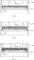
- FIG. 2 shows the same cross-sectional view of a chemical reactor as FIG. 1 with the difference that now catalyst particles 80 are arranged on the knitted fabric knitted fabric 50.
- the average clear mesh width of the knitted fabric knitted fabric 50 is in this case dimensioned so that the catalyst particles 80 are retained.
- FIG. 3 shows further embodiments of the in FIG. 1 and 2 previously described chemical reactor.
- additional knitted fabric mesh 60 inserted U-shaped.
- elastically prestressed knitted fabric knitted fabric 90 for example, a metallic sealing cord made of knit fabric, inserted.
- a layer of inert particles 100 is located between the layer of catalyst particles 80 and the knitted wire knit fabric 50.
- FIG. 4 shows one to the in FIG. 1 reactor shown analog device in which the lying on the support 30 knitted wire fabric 50 is formed continuously through to the reactor wall 10. Additional, round knit fabric knitted fabric 60 is arranged below it and seals the gap between the carrier 30 and reactor wall 10 also from.
- This embodiment has the advantage that the upper knit fabric layer 50 can be easily lifted for maintenance and inspection purposes.
- FIG. 5 corresponds to that in FIG. 5 , with the difference that analogous to FIG. 2 a layer of catalyst particles 80 has now been placed on the knitted fabric 50.
- FIG. 6 shows you one FIG. 3 analogous reactor, wherein on a layer of Inertpumblen 100, the catalyst particles 80 are arranged.
- the gap between the carrier 30 and the reactor wall 10 is sealed by the additional knitwear 60.
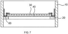
- This knitted fabric 60 is inserted in a U-shape, wherein the reactor wall 10 facing side of the "U” is vertical and the other side of the "U” follows the course of the shape of the support 30, that is, initially perpendicular and then horizontally further on the support 3 runs. Then the knitted wire fabric 50 is placed.
- FIG. 7 shows this course.
- This figure corresponds FIG. 6 wherein only the reactor walls 10, the support ring 20, supports 30, columns 40 and the additional knitwear 60 are shown.
- an elastically biased knitted fabric knitted fabric 90 are inserted.
- reaction product was cooled with water.
- the non-volatile constituents were condensed out and separated from the gaseous components in a downstream separator.
- the liquid components were led out of the separator into a product collection container and collected there.
- In front of the sump was a sampling point where samples of the product could be taken at regular intervals. These were analyzed by gas chromatography for the presence of nitrobenzene. If the nitrobenzene content in the crude product exceeded 500 ppm, the reaction was stopped and the catalyst was regenerated.
- the load was set to 1 g nitrobenzene / (ml of catalyst ⁇ h) and the hydrogen: nitrobenzene ratio to about 80: 1 in all examples.
- the catalyst was an alumina-supported metal catalyst containing 9 g / l support Pd, 9 g / l support V, 3 g / l support Pb on ⁇ -alumina (see EP 0 011 090 A1 ).
- the mean particle size x 50.3 of catalyst particles and, if necessary, inert particles was determined by sieve analysis.
- the reactor was in each case rendered inert with nitrogen and subjected to hydrogen at 240 ° C. over a period of 48 h. Then the nitrobenzene feed was started and increased over 5 hours to the above value.
- the reactor was in turn rendered inert with nitrogen, heated to 270 ° C and then subjected to air flow to burn off coke. This was carried out until no more heat emission could be detected and the CO 2 content in the exhaust gas stream had fallen to less than 0.2% (determined by IR photometry).
- test cycle the next cycle (hereafter referred to as the test cycle) recorded the time of the nitrobenzene breakthrough and cooled the reactor to ambient temperature after regeneration and opened for inspection.
- adiabatic hydrogenation of nitrobenzene to aniline was performed in a reactor equipped with a self-supporting column screen for the catalyst bed.
- the V-wire of the slotted screen had a width of 1.8 mm and a height of 3.7 mm, and the gap width between the V-shaped wires was 0.65 mm.
- the construction of the V-profile wires was normal, so not inverse.
- the slotted screen was made of parallel segments. Each segment lay on a support structure and was bolted to the next support. The connections protrude beyond the screen surface. Corrosion and bending of the profiles and support profiles were prevented by using austenitic steel.
- the outer support ring of the screen was floating on a bearing wall located on the reactor wall. In the cold state, there was a gap of approx. 1 cm between the support ring and the reactor wall.
- the fixed catalyst bed whose catalyst particles had a mean particle size x 50.3 of 1.5 mm, came to lie on the slotted screen.
- nitrobenzene having a concentration of more than 500 ppm was already found in the reaction product after a reaction time of 4 days.
- deep thrombi were detected in the catalyst bed. Below the thrombi, V-profile wires of the gap sieve had come off. Along the reactor wall, the catalyst bed also showed a depression.
- Example V-1 The experimental procedure corresponded to that of Example V-1, wherein in addition the support screen was covered with two 5 cm high layers of inert material.
- the first layer on the screen consisted of 6 mm diameter alumina spheres and the 4 mm diameter alumina spheres layer on top. Only on this second layer was the catalyst bed, whose catalyst particles had a mean particle size x 50.3 of 1.5 mm.
- nitrobenzene was found in the reaction product after a reaction time of about 36 days at a concentration of more than 500 ppm.
- a reaction time of about 36 days Upon inspection of the reactor, no thrombi were detected in the catalyst bed, although again damage to the support screen was observed. Along the reactor wall, the catalyst bed showed no depression. Neither catalyst nor inert material was found at the reactor bottom and in the subsequent apparatus.
- the test procedure corresponded to Comparative Example V-1, wherein additionally the slotted screen was covered with a knitted wire knit fabric of continuous wire.
- the knit fabric had a wire diameter of 0.23 mm, was knitted two times and folded in three layers.
- the knit fabric was made of stainless steel and the average mesh size was 0.65 mm.
- the knitwear was fastened to the split screen by means of bolts.
- the knit fabric was coated with a 5 cm high layer of inert alumina bead material having a mean particle size x 50.3 of 4 mm.
- the fixed catalyst bed whose catalyst particles had a mean particle size x 50.3 of 1.5 mm, came to rest on the inert material.
- Inventive example E-2 (gap sieve, wire mesh, inert material, met. Sealing cord, cat.)
- the experimental procedure corresponded to the example E-1, wherein additionally in the gap between the outer support ring of the slotted screen and the reactor wall, a metallic sealing cord made of knitted wire knitted fabric was inserted, the wire diameter was 0.23 mm and the average clear mesh width was 0.65 mm.
- the sealing cord was still flexible under the reaction conditions and had a diameter of 1.2 cm, so that it was attached by its own spring tension in the gap.
- Example E-3 (simple rust, wire mesh, metallic sealing cord, catalyst)
- adiabatic hydrogenation of nitrobenzene to aniline was performed in a reactor equipped with a simple grid for the catalyst bed.
- the average mesh size of the grate was 30 ⁇ 10 mm. Corrosion and bending of the profiles and support profiles were prevented by using austenitic steel.
- the outer support ring of the grate was floating on a bearing wall located on the reactor wall. It was a cold gap of about 1 cm between the support ring and reactor wall. In this gap, a metallic sealing cord made of knitted wire knit fabric was inserted, the wire diameter of 0.23 mm and the average clear mesh size was 0.65 mm. The sealing cord was still flexible under the reaction conditions and had a diameter of 1.2 cm, so that it was attached by its own spring tension in the gap.
- the grate was covered with a knitted wire knit fabric made of endless wire.
- the knit fabric had a wire diameter of 0.23 mm, was knitted two times and folded in three layers.
- the knit fabric was made of stainless steel and the average mesh size was 0.65 mm.
- the knitwear was fastened to the grate by means of bolts.
- the knits were covered with a 5 cm high layer of alumina ball inert material having a mean particle size x 50.3 of 4 mm.
- the fixed catalyst bed whose catalyst particles had a mean particle size x 50.3 of 1.5 mm, came to rest on the inert material.
- nitrobenzene with a concentration of more than 500 ppm was found in the reaction product after a reaction time of about 900 hours.
- the average clear mesh of the support grid was larger than the diameter of the catalyst or inert material particles.
- the catalyst bed showed no depression. Neither catalyst nor inert material was found at the reactor bottom and in the subsequent apparatus.
- Example E-4 (as Example E-3, but with increased catalyst bed)
- Example E-3 The experimental procedure corresponded to Example E-3 with the difference that the height of the catalyst bed was increased to 50 cm.
- the same amount of nitrobenzene was reacted per unit time as in Comparative Examples and Examples E-1 to E-3.
Description
Die vorliegende Erfindung betrifft einen chemischen Reaktor zur heterogen katalysierten Umsetzung eines Fluids mit einer verbesserten Halteeinrichtung für vom Fluid durchströmte inerte Partikel und/oder Katalysatorpartikel. Sie betrifft weiterhin ein Verfahren zur Durchführung von chemischen Reaktionen mittels eines solchen Reaktors und die Verwendung von Drahtgestrick-Maschenware in chemischen Reaktoren.The present invention relates to a chemical reactor for heterogeneously catalyzed reaction of a fluid with an improved holding device for fluid-flow inert particles and / or catalyst particles. It further relates to a method for carrying out chemical reactions by means of such a reactor and the use of knitted wire mesh in chemical reactors.
Die Hydrierung von Nitroaromaten zu den entsprechenden Aminen in einem axial durchströmten Festbettreaktor kann in einem mehrstufigen Prozess unter adiabatischen Reaktionsbedingungen durchgeführt werden. Solche Hydrierungen verlaufen in periodischen Zyklen, wobei sich Produktionszyklen mit Regenerationszyklen abwechseln, in denen zum Beispiel kohlenstoffhaltige Ablagerungen durch Abbrennen entfernt werden.The hydrogenation of nitroaromatics to the corresponding amines in an axially flowing fixed bed reactor can be carried out in a multi-stage process under adiabatic reaction conditions. Such hydrogenations run in periodic cycles, with production cycles alternating with regeneration cycles in which, for example, carbonaceous deposits are removed by burning off.
Reaktoren für solche Reaktionen haben typischerweise eine zylindrische Form und sind mit einem Spaltsieb ausgestattet, dass als Unterlage für den
Häufige Verwendung finden dabei Spaltsiebe, wie sie zum Beispiel in
Durch den periodischen Betrieb der Reaktoren ist das Sieb thermischen Spannungen unterworfen, die zu Beschädigungen führen. Dies ist insbesondere dann der Fall, wenn exotherme Reaktionen unter adiabaten Bedingungen durchgeführt werden, also die freiwerdende Reaktionswärme vom Reaktionsgas aufgenommen wird, so dass es zu großen Temperatursprüngen im inneren des Reaktors kommt.Due to the periodic operation of the reactors, the screen is subjected to thermal stresses which lead to damage. This is the case in particular when exothermic reactions are carried out under adiabatic conditions, that is, the reaction heat released is absorbed by the reaction gas, so that large temperature jumps occur in the interior of the reactor.
In diesen Fällen kann es nach wenigen Produktionszyklen schon zu Verformungen der V-förmigen, ursprünglich parallel angeordneten Drähte, bis hin zum Ab- oder Zerreißen einzelner Drähte kommen. Die Reparatur eines so beschädigten Siebes ist aufwändig und bringt keinen dauerhaften Erfolg. Um diese Problematik zu minimieren, werden die Spaltsiebe in der Regel an einem schwimmend gelagerten Stützring befestigt, der einen Spalt zur Reaktorwand hin aufweist, um thermische Ausdehnungen auszugleichen.In these cases, deformations of the V-shaped wires, originally arranged in parallel, up to the tearing or tearing of individual wires may occur after only a few production cycles. The repair of such a damaged screen is complex and brings no lasting success. To minimize this problem, the gap sieves are usually at one attached floating support ring, which has a gap to the reactor wall to compensate for thermal expansion.
Gerade bei größeren Reaktoren ist eine absolut ebene Auflagefläche (Tragring) für diesen Ring, wenn überhaupt, nur mit erheblichem Aufwand zu fertigen. Zudem ist es schwierig große Reaktoren exakt rund herzustellen. Als Folge dieser Probleme tritt häufig ein Katalysatorverlust in der Form auf, dass der Katalysator durch Beschädigungen des Spaltsiebs oder durch Öffnungen zwischen Spaltsieb und Reaktorwand beziehungsweise Tragring rieselt.Especially with larger reactors is an absolutely flat bearing surface (support ring) for this ring, if at all, only with considerable effort to manufacture. In addition, it is difficult to produce large reactors exactly round. As a result of these problems, a catalyst loss often occurs in the form that the catalyst trickles through damage to the slotted screen or through openings between slotted screen and reactor wall or support ring.
Verschärft wird die Problematik noch durch den Einsatz immer kleinerer Katalysatorpartikel, die im Allgemeinen eine höhere Effizienz aufweisen, aber auch leichter durch kleine Fehlstellen rieseln. An der Oberfläche der Schüttung entstehen durch den Katalysatorverlust thrombenförmige Vertiefungen. Das Reaktionsgas strömt dann bevorzugt durch die Bereiche mit den Vertiefungen, so dass eine ungleichmäßige Gasströmung entsteht, bis hin zu einem Umgang (Bypass) nicht umgesetzten Eduktes. Des Weiteren kann der auf die Rückseite des Spaltsiebs gewanderte Katalysator Beschädigungen an dahinter befindlichen Apparaten hervorrufen.The problem is exacerbated by the use of ever smaller catalyst particles, which generally have a higher efficiency, but also trickle easily through small defects. At the surface of the bed thrombus-shaped depressions are formed by the loss of catalyst. The reaction gas then flows preferably through the regions with the depressions, so that an uneven gas flow is formed, up to a handling (bypass) unreacted educt. Furthermore, the catalyst traveling on the back side of the slotted screen may cause damage to the apparatus behind it.
Um einen Katalysatordurchtritt auf die andere Seite des Spaltsiebes zu vermeiden, kann der Katalysator auf einer komplexen, mehrschichtigen Schüttung aus Inertpartikeln gelagert werden, wobei der Partikeldurchmesser in der Schicht, die dem Katalysator am nächsten liegt, etwas größer ist als der Partikeldurchmesser des Katalysators und dann mit jeder Schicht zunimmt (Fixed-Bed Reactor Design and Diagnostics, 1990,
Auf diese Weise wird erreicht, dass auf dem Spaltsieb zunächst recht große Inertpartikel liegen, die bei kleineren Fehlstellen noch nicht durch das Sieb rieseln können. Nachteilig an dieser Lösung ist einerseits, dass ein nicht unerheblicher Teil des Reaktors mit Inertmaterial gefüllt wird und nicht mehr für den eigentlichen Katalysator zur Verfügung steht und andererseits, dass das Einbringen der verschiedenen Schichten in den Reaktor aufwändig ist. Soll das Inertmaterial bei einer Neubefüllung des Reaktors wiederverwendet werden, so erfordert dies ein mehrstufiges Sieben des aus dem Reaktor entnommenen Materials, um die unterschiedlich großen Partikel voneinander zu trennen.In this way it is achieved that initially lie on the slotted screen quite large inert particles that can not trickle through the sieve at smaller flaws. A disadvantage of this solution is, on the one hand, that a not inconsiderable part of the reactor is filled with inert material and is no longer available for the actual catalyst and, on the other hand, that the introduction of the various layers into the reactor is complicated. If the inert material is to be reused in a refilling of the reactor, this requires a multistage screening of the material removed from the reactor in order to separate the differently sized particles from one another.
Es war daher Aufgabe der Erfindung, einen Reaktor bereitzustellen, bei dem auch im Falle wiederholter thermischer Beanspruchung ein Durchtritt von Katalysator auf die Rückseite der Tragkonstruktion für den Katalysator verhindert wird, wobei die Tragkonstruktion kostengünstig, der Instandhaltungsaufwand gering und das Befüllen des Reaktors mit der Katalysatorschüttung einfach sein soll.It was therefore an object of the invention to provide a reactor in which even in the case of repeated thermal stress, a passage of catalyst on the back of the support structure for the catalyst is prevented, the support structure cost, the maintenance costs low and filling the reactor with the catalyst bed should be easy.
Erfindungsgemäß wird die Aufgabe gelöst durch einen chemischen Reaktor zur heterogen katalysierten Umsetzung eines Fluids, umfassend eine vom Fluid durchströmte Halteeinrichtung für Partikel, wobei die in Strömungsrichtung des Fluids gesehen stromaufwärts gelegene Seite der Halteeinrichtung Drahtgestrick-Maschenware umfasst, auf der Katalysatorpartikel angeordnet sind oder auf der eine Schicht von gegenüber dem Fluid inerten Partikeln angeordnet ist und auf dieser Schicht Katalysatorpartikel angeordnet sind, wobei die Drahtgestrick-Maschenware auf einem Träger angeordnet ist und der Träger in Strömungsrichtung des Fluids durchgehende Öffnungen umfasst, und wobei die durchschnittliche lichte Maschenweite des Drahtgestricks kleiner als die mittlere Partikelgröße X50.3 der Partikel ist, welche durch eine mit einer Vibrationssiebmaschine mit Siebsatz durchgeführte Siebanalyse unter Einhaltung der Bestimmungen der DIN 66165 (Fassung vom April 1987) ermittelt wird.
Maschenwaren sind beispielsweise aus der Textil- und Schmuckindustrie bekannt. Ganz allgemein bezeichnet eine Maschenware ein Flächengebilde, bei denen eine mittels eines Fadens oder mehrerer Fäden gebildete Schleife in eine andere Schleife hineingeschlungen ist, wobei die "Maschen" entstehen. Davon zu unterscheiden sind Gewebe, bei denen die Fläche durch Verkreuzen von zwei Fadensystemen hergestellt wird. Maschenware weist eine höhere Dehnbarkeit und Elastizität als Gewebe auf. Maschenwaren können in Strick-, Wirk- und Kulierwaren unterteilt werden. Für die Durchführung der vorliegenden Erfindung sind grundsätzlich alle drei geeignet. Besonders bevorzugt werden jedoch Strick- und/oder Kulierwaren eingesetzt, da diese noch elastischer sind als die (ohnehin schon elastischen) Wirkwaren. In der vorliegenden Erfindung kommt eine Drahtgestrick-Maschenware zum Einsatz, d. h. die erfindungsgemäße Maschenware wird aus Drähten und/oder Metallfäden gefertig. Dabei umfasst der Begriff "Drahtgestrick" im Rahmen der vorliegenden Erfindung alle Arten von Maschenware, also auch Wirkware. Die Herstellung des Drahtgestricks erfolgt mit an sich bekannten Drahtverarbeitungsmaschinen, wie sie beispielsweise für Anwendungen in der Automobilindustrie, der Verfahrens- und Umwelttechnik gebräuchlich sind (z. B. Drahtstrickmaschinen). Geeignet für die Durchführung der vorliegenden Erfindung sind beispielsweise Drahtgestricke der Firma DHD Technology.
Durch die Flexibilität der Maschenware ist dafür gesorgt, dass sie im periodischen Betrieb bei unterschiedlichen Temperaturen nicht beschädigt wird. Gleichzeitig verhindert die 3-dimensionale Struktur der Maschenware, dass sich zu viele Maschen mit Partikeln zusetzen und der Gasfluss behindert wird.
Unter Partikeln können im Sinne dieser Erfindung sowohl Katalysatorpartikel (z. B. ein auf Aluminiumoxidkugeln geträgerter Edelmetallkatalysator) als auch inerte Partikel (z. B. Aluminiumoxidkugeln) verstanden werden. Bevorzugt werden Partikel eingesetzt, die mindestens im Wesentlichen kugelförmig sind, d. h., deren evtl. vorhandene Abweichungen von der idealen Kugelgeometrie so gering sind, dass sie sich in der Praxis wie ideale Kugeln verhalten. Grundsätzlich ist die Erfindung jedoch auch auf asymmetrisch geformte Partikel anwendbar. Als erster Anhaltspunkt für die mittlere Partikelgröße dienen die Angaben des Herstellers.According to the invention, the object is achieved by a chemical reactor for the heterogeneously catalyzed reaction of a fluid, comprising a holding device for particles through which fluid flows, wherein the upstream side of the holding device, viewed in the flow direction of the fluid, comprises knitted wire mesh on which catalyst particles are arranged or on which a layer of particles inert to the fluid is arranged and arranged on this layer of catalyst particles, wherein the knitted fabric knitted fabric is arranged on a support and the carrier in the flow direction of the fluid through openings comprises, and wherein the average clear mesh size of the wire mesh smaller than that mean particle size X 50.3 of the particles which is determined by a sieve analysis carried out with a vibrating sieve with sieve set in compliance with the provisions of DIN 66165 (version of April 1987).
Knitted fabrics are known for example from the textile and jewelry industry. More generally, a knit fabric refers to a fabric in which a loop formed by means of a thread or a plurality of threads is looped into another loop to form the "stitches". This should be distinguished from fabrics in which the surface is made by crossing two thread systems. Knitted fabric has a higher extensibility and elasticity than fabric. Knitwear can be divided into knit, knitting and weft. In principle, all three are suitable for carrying out the present invention. However, particularly preferred knitting and / or Kulierwaren be used, since they are even more elastic than the (already elastic) hosiery. In the present invention, a knitted fabric knitted fabric is used, ie the knit fabric according to the invention is made of wires and / or metal threads. The term in the context of the present invention includes "wire knitted fabric" all kinds of knitted fabrics, including knitted fabric. The production of the wire knit takes place with wire processing machines known per se, such as are commonly used for applications in the automotive industry, process engineering and environmental technology (eg wire knitting machines). Wire knits from DHD Technology, for example, are suitable for carrying out the present invention.
The flexibility of the knit fabric ensures that it is not damaged during periodic operation at different temperatures. At the same time, the 3-dimensional structure of the knitted fabric prevents too much mesh with particles and obstructs the gas flow.
For the purposes of this invention, particles can be understood as meaning both catalyst particles (for example a noble metal catalyst supported on aluminum oxide spheres) and inert particles (for example aluminum oxide spheres). Preferably, particles are used which are at least substantially spherical, that is, whose possibly existing deviations from the ideal spherical geometry are so small that they behave in practice as ideal spheres. in principle However, the invention is also applicable to asymmetrically shaped particles. The first indication of the average particle size is provided by the manufacturer.
Für die genaue Bestimmung der mittleren Partikelgröße ist eine "Partikelgrößenanalyse" erforderlich. Im Rahmen dieser Erfindung erfolgt diese durch Siebanalyse. Erfindungsgemäß wird dabei als mittlere Partikelgröße der massebezogene Wert ("x50,3") verwendet.For accurate determination of mean particle size , a "particle size analysis" is required. In the context of this invention, this is done by sieve analysis. According to the invention, the mass-related value ("x 50.3 ") is used as mean particle size.
Zur Bestimmung der mittleren Partikelgröße im Rahmen der vorliegenden Erfindung wird nun so vorgegangen, dass man zunächst eine repräsentative Probe der zu stützenden Partikel einer Siebanalyse unterwirft und das Ergebnis massebezogen auswertet. Die Siebanalyse erfolgt dabei unter Verwendung einer Vibrationssiebmaschine (z. B. Modell AS 200 digit der Firma Retsch), in welcher die Analysensiebe mit aufsteigender Maschenweite übereinander zu einem Siebsatz angeordnet werden. Die Auswahl der Analysensiebe (Durchmesser und Maschenweite) hängt in erster Linie von der Siebgutmenge und der zu erwartenden (ggf. sind Vorversuche nötig) Partikelgrößenverteilung ab. Die Anzahl der Siebe und die Abstufungen der nominalen Öffnungsweiten sollten so ausgewählt werden, dass möglichst das gesamte Partikelspektrum der Probe in Fraktionen aufgeteilt wird. Bei der Durchführung der Siebanalyse ist sicherzustellen, dass der maximale Durchgang an Siebgut (optimaler Aussiebegütegrad) erzielt wird. Erforderlichenfalls (wenn beispielsweise neue Partikel, mit denen noch keine Betriebserfahrung vorliegt, eingesetzt werden sollen) müssen geeignete Siebzeiten und Amplituden in Vorversuchen experimentell ermittelt werden. Ein erster Anhaltspunkt für die Amplitude ergibt sich aus der Beobachtung der Siebgutbewegung. Diese sollte weder zu schwach noch zu stark sein. Die optimale Siebzeit ist erreicht, wenn sich die Masse des Siebdurchgangs in einer Minute um weniger als 0,1 % der Aufgabemenge verändert (DIN 66165, Fassung vom April 1987). Der Fachmann ist mit den hier nur kurz umrissenen Methoden vertraut.In order to determine the mean particle size in the context of the present invention, the procedure is now to first subject a representative sample of the particles to be supported to a sieve analysis and to evaluate the result on a mass basis. Sieve analysis is carried out using a vibrating sieve machine (eg model AS 200 digit from Retsch) in which the test sieves are arranged one above the other with increasing mesh size to form a sieve. The selection of the test sieves (diameter and mesh size) depends primarily on the amount of screenings and the expected (if necessary preliminary tests are necessary) particle size distribution. The number of sieves and the gradations of the nominal opening widths should be selected so that as far as possible the entire particle spectrum of the sample is divided into fractions. When carrying out the sieve analysis, it must be ensured that the maximum throughput of screenings (optimum screening grade) is achieved. If necessary (for example, if new particles with which no operating experience is yet to be used), suitable screening times and amplitudes must be determined experimentally in preliminary tests. A first indication of the amplitude results from the observation of Siebgutbewegung. This should neither be too weak nor too strong. The optimum sieving time is reached when the mass of the sieve passage changes by less than 0.1% of the feed quantity in one minute (DIN 66165, version of April 1987). The skilled person is familiar with the methods outlined here only briefly.
Die Siebanalyse liefert als Ergebnis die Partikelgrößenverteilung der gemessenen Partikel. Das Ergebnis wird vorzugsweise graphisch dargestellt, indem der Massenanteil der einzelnen Fraktionen ("p3") in einem Balkendiagramm und die aus den prozentualen Anteilen kumulierte Summenkurve ("Q3") über den nominalen Sieböffhungsweiten (x) aufgetragen werden. Der Fachmann kann die mittlere Partikelgröße x50,3 (d. h. 50 Massen-% der Partikel sind kleiner als der entsprechende Wert x) leicht errechnen, entweder manuell oder bevorzugt durch Computer-gestützte Auswerteprogramme.The sieve analysis yields as a result the particle size distribution of the measured particles. The result is preferably plotted by plotting the mass fraction of the individual fractions ("p 3 ") in a bar graph and the cumulative cumulative cumulative curve ("Q 3 ") over the nominal sieve opening widths (x). The person skilled in the art can easily calculate the mean particle size x 50.3 (
Zeigt dieses erste Resultat eine ausreichende Homogenität der Probe an, so ist die so ermittelte mittlere Partikelgröße x50,3 der zur Durchführung der Erfindung erforderliche Wert. Unter einer ausreichenden Homogenität wird in diesem Zusammenhang verstanden, dass die Partikelgrößenverteilung monomodal ist und dass jeweils maximal 0,1 Massen-% aller Partikel im Bereich zwischen ½ x50,3 und 2/3 x50,3 bzw. im Bereich zwischen 1⅓ x50,3 und 1½ x50,3 liegen. Ferner sollten keine Partikel kleiner als ½ x50,3 oder größer als 1½ x50,3 sein. Zeigt dieses erste Resultat keine ausreichende Homogenität der Probe in obigem Sinne an, so werden die zu stützenden Partikel durch Siebung in großtechnischem Maßstab homogenisiert, d. h. Staubanteile und nicht mehr einsetzbare Bruchstücke werden abgetrennt. Dies wird so lange durchgeführt, bis die genannten Anforderungen an die Homogenität erfüllt sind.If this first result indicates sufficient homogeneity of the sample, then the average particle size determined in this way is x 50.3 of the value required for carrying out the invention. Under one sufficient homogeneity is understood in this context that the particle size distribution is monomodal and that in each case a maximum of 0.1% by mass of all particles in the range between ½ x 50.3 and 2/3 of x in the range between 50.3 and 1⅓ x 50 3 and 1½ x 50.3 lie. Furthermore, particles should not be smaller than ½ x 50.3 or larger than 1½ x 50.3 . If this first result does not indicate sufficient homogeneity of the sample in the above sense, then the particles to be supported are homogenized by sieving on an industrial scale, ie dust fractions and fragments which are no longer usable are separated off. This is done until the stated requirements for homogeneity are met.
Der chemische Reaktor kann beispielsweise ein axial durchströmter Festbettreaktor sein, wie er in der Hydrierung von Nitrobenzol zu Anilin eingesetzt wird. Das im Reaktor umzusetzende Fluid kann flüssig, gasförmig oder überkritisch sein. Es kann einen Reaktanden oder eine Mischung aus mehreren Reaktanden enthalten.The chemical reactor can be, for example, an axially flow-through fixed bed reactor, as used in the hydrogenation of nitrobenzene to aniline. The fluid to be reacted in the reactor can be liquid, gaseous or supercritical. It may contain a reactant or a mixture of several reactants.
Wie später eingehender beschrieben werden wird, können die von der Drahtgestrick-Maschenware zurückgehaltenen Partikel sowohl Katalysatorpartikel als auch inerte Partikel sein.As will be described in more detail later, the particles retained by the knitted fabric can be both catalyst particles and inert particles.
Die Art der Drahtgestrick-Maschenware ist zunächst nicht weiter festgelegt. Es kann sich um einadrigen oder mehradrigen Draht handeln, der auf beliebige Weise verstrickt wurde. So können die Gestricke beispielsweise bis zu 5 runde, flache, glatte und/oder gewellte Fäden enthalten. Verstrickte Materialien können unter anderem Stahl, Edelstähle wie 1.4571, Kupfer, Monel (2.4360) oder Aluminium sein. Neben Drahtgestricken aus Flachstrickmaschinen können zum Beispiel auch zweilagige Drahtgestrickbahnen verwendet werden, die durch das Zusammendrücken von Drahtgestrickschläuchen, die mit Rundstrickmaschinen gefertigt werden, bezüglich einer durch die Mittelachse der Drahtgestrickschläuche verlaufenden Faltebene entstehen.The type of knitted fabric knitted fabric is initially not specified. It may be single-wire or multi-wire, which has been entangled in any way. For example, the knitted fabrics may contain up to 5 round, flat, smooth and / or wavy threads. Enmeshed materials may include steel, stainless steels such as 1.4571, copper, Monel (2.4360) or aluminum. In addition to knitted wire of flat knitting machines, for example, two-layer wire knitting paths can be used, which result from the compression of wire knit hoses, which are made with circular knitting machines with respect to a running through the center axis of the wire knit hoses folding level.
Erfindungsgemäß ist vorgesehen, dass die durchschnittliche lichte Maschenweite des Drahtgestricks kleiner ist als die mittlere Partikelgröße x50,3 der Partikel, welche in der Halteeinrichtung zur Aufnahme bestimmt sind. Sie bezeichnet den Innenabstand (nicht den Abstand von Drahtmitte zu Drahtmitte) zweier benachbarter Maschenschenkel am Punkt der größten Ausdehnung einer Masche. Bevorzugt liegt das Verhältnis zwischen Maschenlänge, also dem Abstand zweier benachbarter Maschenköpfe, und Maschenweite zwischen 4 : 1 und 0,5 : 1, besonders bevorzugt zwischen 2 : 1 und 1 : 1. Die durchschnittliche lichte Maschenweite bezeichnet dann den Durchschnittswert aller lichten Weiten einzelner Maschen einer Drahtgestrick-Maschenware. Die durchschnittliche lichte Maschenweite wird bei der Herstellung der Drahtgestrick-Maschenware nach dem Fachmann bekannten Methoden eingestellt (z. B. Anzahl, Abstand und Dicke der Nadeln am Strickkopf, Anzahl und Stärke der Drähte usw.). Die Verwendung von Maschenware mit uneinheitlicher Maschwenweite (d. h. Unterschieden in den Maschenweiten, die über normale fertigungsbedingte Toleranzen hinausgehen) ist nicht bevorzugt, aber grundsätzlich auch möglich. In diesem Fall ist bevorzugt die lichte Maschenweite der größten Masche kleiner als die mittlere Partikelgröße x50,3.According to the invention, it is provided that the average clear mesh width of the wire mesh is smaller than the mean particle size x 50.3 of the particles which are intended to be received in the holding device. It denotes the inside distance (not the distance from the middle of the wire to the center of the wire) of two adjacent mesh legs at the point of greatest expansion of a mesh. Preferably, the ratio between mesh length, ie the distance between two adjacent mesh heads, and mesh size between 4: 1 and 0.5: 1, more preferably between 2: 1 and 1: 1. The average clear mesh then denotes the average value of all clear widths of individual Mesh of a knitted knitted fabric. The average clear mesh size is set in the production of knitted wire knit fabric by methods known to the person skilled in the art (eg number, spacing and thickness of the needles on the knitting head, number and thickness of the wires, etc.). The use of non-uniform mesh sizes (ie, differences in mesh sizes that exceed normal manufacturing tolerances) is not preferred, but generally possible. In this case, the clear mesh size of the largest mesh is preferably smaller than the mean particle size x 50.3 .
Die Halteeinrichtung für Partikel kann im einfachsten Fall durch im Reaktor aufgespannte Drahtgestrick-Maschenware alleine gebildet werden. Es ist jedoch bevorzugt, dass die Drahtgestrick-Maschenware durch einen Träger unterstützt wird, um den auftretenden mechanischen Belastungen gewachsen zu sein. Dann sind sowohl der Träger als auch die Drahtgestrick-Maschenware Teil der Halteeinrichtung für Partikel. Zusammen mit Katalysatorpartikeln wird hieraus das Katalysatorbett gebildet.The holding device for particles can be formed in the simplest case by knitted fabric knitted in the reactor alone. However, it is preferred that the knit knitted fabric be supported by a carrier to cope with the mechanical stresses involved. Then both the carrier and the knitted fabric are part of the holding device for particles. Together with catalyst particles, the catalyst bed is formed from this.
Die Lage der Drahtgestrick-Maschenware in der Halteeinrichtung für Partikel im vom Fluid durchströmten Reaktor ergibt sich aus der Funktion der Maschenware zur Zurückhaltung von Partikeln. Sie befindet sich daher auf der stromaufwärts gelegenen Seite der Halteeinrichtung.The position of the knitted fabric in the holding device for particles in the reactor through which the fluid flows results from the function of the knitwear for the retention of particles. It is therefore located on the upstream side of the holding device.
Vorteilhaft bei dem erfindungsgemäßen Reaktor ist weiterhin, dass ein einfaches Spaltsieb als Träger verwendet werden kann. Die Verwendung eines aufwändig gefertigten Spaltsiebes ist nicht erforderlich, sondern es kann auch ebenfalls ein einfacher Rost zur Anwendung kommen. Die Maschenware wird auf das Spaltsieb oder den Rost aufgelegt und gegebenenfalls fixiert.An advantage of the reactor according to the invention is further that a simple slotted screen can be used as a carrier. The use of an elaborate slotted screen is not required, but it can also be a simple rust used. The knitwear is placed on the slotted screen or the grate and optionally fixed.
Die aufgelegte Maschenware übernimmt nun die Funktion der Katalysatorrückhaltung. Dadurch kann nicht nur eine Beschädigung des Spaltsiebes in Kauf genommen werden, sondern die Öffnungen im Spaltsieb können von vornherein größer ausgelegt werden.The laid-up knitwear now assumes the function of catalyst retention. As a result, not only damage to the slotted screen can be accepted, but the openings in the slotted screen can be made larger from the outset.
Hieraus ergibt sich ein weiterer Vorteil: Durch die größeren Öffnungen ist es möglich, die Dicke des Spaltsiebes oder Rostes zu erhöhen, ohne dass Verstopfungen zu befürchten sind. Dadurch wird wiederum die Steifigkeit der die Maschenware tragenden Konstruktion erhöht, so dass höhere Katalysatormengen getragen werden können und auch höhere Druckverluste und die sich daraus ergebenden Lasten verkraftet werden. Es kann sogar auf die Schüttung mit Inertmaterial verzichtet werden, wodurch nochmals höhere Katalysatormengen zum Einsatz kommen können.This results in a further advantage: Due to the larger openings, it is possible to increase the thickness of the slotted screen or grate without blockages being feared. This in turn increases the rigidity of the construction carrying the knitwear so that higher amounts of catalyst can be carried and also withstand higher pressure drops and the resulting loads. It can even be dispensed with the bed of inert material, which can be used again higher amounts of catalyst.
Ausführungsformen der Erfindung werden nachfolgend geschildert, wobei die Ausführungsformen frei miteinander kombiniert werden können, sofern sich nicht aus dem Zusammenhang eindeutig das Gegenteil ergibt.Embodiments of the invention are described below, wherein the embodiments can be freely combined with each other, unless clearly the opposite results from the context.
In einer Ausführungsform des erfindungsgemäßen Reaktors beträgt die durchschnittliche lichte Maschenweite des Drahtgestricks ≥ 20 % bis ≤ 80 % der mittleren Partikelgröße x50,3. Vorzugsweise beträgt dieser Wert ≥ 30 % bis ≤ 60 % und mehr bevorzugt ≥ 40 % bis ≤ 50 %. Auf diese Weise wird besonders verhindert, dass durch in den Maschen verfangene Partikel ein unerwünschter Druckverlust während des Betriebes des Reaktors auftritt.
In einer weiteren Ausführungsform des erfindungsgemäßen Reaktors beträgt die Dehnbarkeit der Drahtgestrick-Maschenware unter mechanischer und/oder thermischer Belastung in Flächenrichtung ≥ 1 %, bevorzugt ≥ 2 %. Die Dehnbarkeit in Flächenrichtung sollte 50 %, bevorzugt 25 %, bevorzugt 10 % nicht überschreiten. Auf diese Weise wird besonders sichergestellt, dass sich die Maschenware den thermischen Ausdehnungen des Reaktors anpasst ohne Schaden zu nehmen und ohne, dass Partikel durch die Maschen fallen.
In einer weiteren Ausführungsform des erfindungsgemäßen Reaktors beträgt der Drahtdurchmesser der Drahtgestrick-Maschenware ≥ 0,03 mm bis ≤ 1 mm. Vorzugsweise beträgt der Durchmesser des Drahts, aus dem die Maschenware gestrickt ist, ≥ 0,1 mm bis ≤ 0,5 mm und mehr bevorzugt ≥ 0,2 mm bis ≤ 0,3 mm. Auf diese Weise wird besonders sichergestellt, dass der Draht eine ausreichende Stabilität bei gleichzeitig geringem Gewicht und großer Durchgangsfläche für das Fluid aufweist.
In einer weiteren Ausführungsform des erfindungsgemäßen Reaktors beträgt die Höhe der Drahtgestrick-Maschenware in der Halteeinrichtung für Partikel ≥ 3 mm bis ≤ 100 mm. Dieses lässt sich beispielsweise durch mehrfach gefaltetes Auflegen der Maschenware auf einem Träger erreichen. Vorzugsweise beträgt die Höhe ≥ 5 mm bis ≤ 80 mm und mehr bevorzugt ≥ 10 mm bis ≤ 50 mm. So wird der Durchtritt von Teilchen auf die stromabwärts liegende Seite der Maschenware besonders zuverlässig verhindert und es verbleiben stets freie Kanäle für das durchströmende Fluid.
In einer weiteren Ausführungsform des erfindungsgemäßen Reaktors ist die Drahtgestrick-Maschenware eine durch mechanische Einwirkung verformte Drahtgestrick-Maschenware. Hierzu kann die Maschenware gewalzt oder zwischen zwei Zylinderrollen oder Zahnrädern hindurchgeführt werden. Auf diese Weise verformte Maschenware hat entweder eine geringe Höhe, um den verfügbaren Raum für Katalysator im Reaktor zu maximieren (gewalzt) oder erhält eine stärker dreidimensionale Struktur (durch Zahnräder), so dass mit geringem Materialaufwand eine höhere Auflage aus Maschenware erreicht werden kann. Diese weist dann einen besonders geringen Druckverlust und eine besonders geringe Neigung zur Verstopfung der Maschen auf. Im erfindungsgemäßen Reaktor ist die Drahtgestrick-Maschenware auf einem Träger angeordnet und der Träger umfasst in Strömungsrichtung des Fluids durchgehende Öffnungen. Wie bereits geschildert sind bevorzugte Träger Spaltsiebe und Gitterroste. Der Träger lässt sich auf einem Tragring auf der Innenseite der Reaktorwand schwimmend lagern, um die thermische Ausdehnung während des Betriebes auszugleichen.
Vorzugsweise ist hierbei zwischen dem Träger und der Wand des Reaktors zusätzlich Drahtgestrick-Maschenware angeordnet. Hierdurch wird ein zwecks Kompensation der thermischen Ausdehnung bestehender Spalt gegen Partikeldurchtritt gesichert. Vorzugsweise ist diese Drahtgestrick-Maschenware eine metallische Dichtschnur aus Maschenware. Es ist günstig, wenn sie aus demselben Material wie die auf dem Träger befindliche Maschenware besteht.
In einer besonders bevorzugten Ausführungsform des erfindungsgemäßen Reaktors ist die zwischen dem Träger und der Wand des Reaktors zusätzlich befindliche Drahtgestrick-Maschenware U-förmig angeordnet und eine elastisch vorgespannte weitere Drahtgestrick-Maschenware ist in die hierdurch gebildete Vertiefung eingebracht. Beispielsweise kann dieses eine metallische Dichtschnur aus Maschenware sein.
Die Schenkel des "U" können jeder für sich oder zusammen senkrecht stehen, um beispielsweise der Form der Reaktorwand angepasst zu sein. Es ist aber auch möglich, dass die Schenkel zumindest teilweise einen waagerechten Verlauf nehmen. Dann können sie auf einem Spaltsieb oder Gitterrost aufliegen. Hierauf kann dann weitere Maschenware gelegt werden.
Die Art der Vorspannung kann sowohl eine Kompression als auch eine Dehnung sein. Vorzugsweise wird die Dichtschnur vor dem Einbringen komprimiert, so dass sie sich anschließend ausdehnt. Dann werden die beiden nach oben stehenden Seiten des "U" an den Träger und/oder einen Tragring sowie an die Reaktorwand angedrückt. Damit wird sicher und dauerhaft vermieden, dass Inert- oder Katalysatorpartikel etwaige Fehlstellen zwischen Träger, Tragring und Reaktorwand beziehungsweise Auflagefläche des Tragringes passieren. Die metallische Dichtschnur ist dabei federelastisch und gleicht zum einen die Passungenauigkeit zwischen Spaltsieb und Reaktorwand und zum anderen die Änderungen in der Breite des Spaltes zwischen Spaltsieb und Reaktorwand auch bei Temperaturwechseln aus.In one embodiment of the reactor according to the invention, the average mesh size of the wire mesh is ≥ 20% to ≦ 80% of the mean particle size × 50.3 . This value is preferably ≥ 30% to ≦ 60%, and more preferably ≥ 40% to ≦ 50%. In this way it is particularly prevented that an undesired pressure loss occurs during operation of the reactor due to particles caught in the mesh.
In a further embodiment of the reactor according to the invention, the extensibility of the knitted wire knit fabric under mechanical and / or thermal stress in the surface direction is ≥ 1%, preferably ≥ 2%. The extensibility in the plane direction should not exceed 50%, preferably 25%, preferably 10%. In this way, it is particularly ensured that the knitted fabric adapts to the thermal expansion of the reactor without being damaged and without particles falling through the mesh.
In a further embodiment of the reactor according to the invention, the wire diameter of the knit knitted fabric is ≥ 0.03 mm to ≦ 1 mm. Preferably, the diameter of the wire from which the knitted fabric is knitted is ≥ 0.1 mm to ≦ 0.5 mm, and more preferably ≥ 0.2 mm to ≦ 0.3 mm. In this way it is particularly ensured that the wire has sufficient stability with low weight and large passage area for the fluid.
In a further embodiment of the reactor according to the invention, the height of the knitted wire knitted fabric in the holding device for particles is ≥ 3 mm to ≦ 100 mm. This can be achieved for example by repeatedly folded laying the knitwear on a support. The height is preferably ≥ 5 mm to ≦ 80 mm and more preferably ≥ 10 mm to ≦ 50 mm. Thus, the passage of particles on the downstream side of the knitwear is particularly reliably prevented and there are always free channels for the fluid flowing through.
In a further embodiment of the reactor according to the invention, the knitted wire knitted fabric is a knitted fabric knitted by mechanical action. For this purpose, the knitted fabric can be rolled or passed between two cylindrical rollers or gears. Mesh so deformed in this way either has a small height to maximize (roll) the available space for catalyst in the reactor, or gets a more three-dimensional structure (through gears), so that a higher overlay of knitwear can be achieved with less material. This then has a particularly low pressure loss and a particularly low tendency to block the mesh. In the reactor according to the invention, the knitted fabric is arranged on a support and the support comprises in the direction of flow of the fluid through openings. As already described, preferred carriers are slot screens and gratings. The carrier can be stored on a support ring floating on the inside of the reactor wall to compensate for the thermal expansion during operation.
Preferably, in this case between the support and the wall of the reactor in addition knitted wire mesh is arranged. As a result, an existing gap for compensation of the thermal expansion gap is protected against particle passage. Preferably, this knitted fabric knitted fabric is a metallic sealing cord made of knitwear. It is favorable if it consists of the same material as the knitwear on the carrier.
In a particularly preferred embodiment of the reactor according to the invention, the wire mesh knitwear additionally located between the support and the wall of the reactor is arranged in a U shape and an elastically prestressed further knitted wire knit fabric is introduced into the depression formed thereby. For example, this may be a metallic sealing cord made of knitwear.
The legs of the "U" can each stand alone or together vertically, for example, to be adapted to the shape of the reactor wall. But it is also possible that the legs take at least partially a horizontal course. Then they can rest on a slotted screen or grid. On this then further knitwear can be placed.
The type of bias can be both compression and elongation. Preferably, the sealing cord is compressed prior to insertion, so that it then expands. Then the two upstanding sides of the "U" to the support and / or a support ring and pressed against the reactor wall. This safely and permanently avoided that inert or catalyst particles happen any defects between the carrier, support ring and reactor wall or support surface of the support ring. The metallic sealing cord is resilient and balances on the one hand, the fit inaccuracy between slotted screen and reactor wall and on the other hand, the changes in the width of the gap between the slotted screen and the reactor wall even with temperature changes.
Im erfindungsgemäßen Reaktor sind in der Halteeinrichtung - in einer Alternative der Erfindung - Katalysatorpartikel auf der Drahtgestrick-Maschenware angeordnet. Geeignete Katalysatoren sind unter anderem in
- (a)1 - 100 g/l Träger mindestens eines Metalls der Gruppen 8 bis 12 des Periodensystems der Elemente, und
- (b)0 - 100 g/l Träger mindestens eines Übergangsmetalls der Gruppen 4 bis 6 und 12 des Periodensystems der Elemente, sowie
- (c)0 - 100 g/l Träger mindestens eines Metalls der Hauptgruppenelemente der Gruppen 14 und 15 des Periodensystems der Elemente
Im erfindungsgemäßen Reaktor ist in der Halteeinrichtung - in einer weiteren Alternative der Erfindung - auf
der Drahtgestrick-Maschenware eine Schicht von gegenüber dem Fluid inerten Partikeln angeordnet und es sind auf dieser Schicht Katalysatorpartikel angeordnet. Gegenüber dem Fluid inerte Partikel sind katalytisch inaktiv und reagieren nicht mit dem Fluid. Wenn solche Partikel als Zwischenschicht auf der Maschenware aufliegen, ist es möglich, kleinere und somit aktivere Katalysatorpartikel einzusetzen.In the reactor according to the invention in the holding device - in an alternative of the invention - catalyst particles are arranged on the knitted fabric knitted fabric. Suitable catalysts include, inter alia
- (a) 1-100 g / l of carrier of at least one metal of groups 8 to 12 of the Periodic Table of the Elements, and
- (b) 0-100 g / l of carrier of at least one transition metal of Groups 4 to 6 and 12 of the Periodic Table of the Elements, as well as
- (c) 0-100 g / l of carrier of at least one metal of the main group elements of Groups 14 and 15 of the Periodic Table of the Elements
In the reactor according to the invention is in the holding device - in a further alternative of the invention - on
the wire mesh knitted fabric arranged a layer of particles inert to the fluid and there are arranged on this layer catalyst particles. Particles inert to the fluid are catalytically inactive and do not react with the fluid. If such particles rest as an intermediate layer on the knitted fabric, it is possible to use smaller and thus more active catalyst particles.
Ein weiterer Gegenstand der vorliegenden Erfindung ist ein Verfahren zur Umsetzung eines Fluids, wobei die Umsetzung in einem erfindungsgemäßen Reaktor in Gegenwart von heterogenen Katalysatorpartikeln durchgeführt wird und die Katalysatorpartikel in der Halteeinrichtung für Katalysatorpartikel angeordnet sind. Mit eingeschlossen ist der Fall, dass sich eine Zwischenschicht aus inerten Partikeln im Katalysatorbett befindet. Der Vorteil des erfindungsgemäßen Verfahrens liegt insbesondere in längeren Standzeiten, bis eine erneute Wartung notwendig ist.Another object of the present invention is a method for reacting a fluid, wherein the reaction is carried out in a reactor according to the invention in the presence of heterogeneous catalyst particles and the catalyst particles are arranged in the holding means for catalyst particles. Included is the case that there is an intermediate layer of inert particles in the catalyst bed. The advantage of the method according to the invention lies in particular in longer service life, until a renewed maintenance is necessary.
In einer Ausführungsform des erfindungsgemäßen Verfahrens wird weiterhin nach Beendigung der Umsetzung der Reaktor in Gegenwart von Sauerstoff auf eine Temperatur von ≥ 200 °C bis ≤ 400 °C erhitzt. Es hat sich gezeigt, dass erfindungsgemäße Reaktoren auch diesem Abbrennen von Kohlenstoffablagerungen in vorteilhafter Weise gewachsen sind.In one embodiment of the process according to the invention, after completion of the reaction, the reactor is further heated in the presence of oxygen to a temperature of ≥ 200 ° C to ≦ 400 ° C. It has been found that reactors according to the invention are also able to cope with this burn-off of carbon deposits in an advantageous manner.
In einer weiteren Ausführungsform des erfindungsgemäßen Verfahrens umfasst das Fluid aromatische Nitroverbindungen und Wasserstoff. Insbesondere kann es sich um die Hydrierung von Nitrobenzol zu Anilin handeln. Das erfindungsgemäße Verfahren kann länger betrieben werden, bis es zu einem erhöhten Nitrobenzolgehalt (Nitrobenzoldurchbruch) im Endprodukt kommt.In a further embodiment of the method according to the invention, the fluid comprises aromatic nitro compounds and hydrogen. In particular, it may be the hydrogenation of nitrobenzene to aniline. The process according to the invention can be operated for a longer time until an increased nitrobenzene content (nitrobenzene breakthrough) in the end product occurs.
In einer weiteren Ausführungsform des erfindungsgemäßen Verfahrens wird die Umsetzung adiabatisch durchgeführt. Dieses Verfahren wird zum Beispiel in
Ein zusätzlicher Aspekt der vorliegenden Erfindung ist die Verwendung von Drahtgestrick-Maschenware als Halteeinrichtung für Katalysatorpartikel und/oder inerte Partikel in chemischen Reaktoren, wie im Anspruch 12 spezifiziert. Zu Details und bevorzugten Ausführungsformen wird zur Vermeidung von Wiederholungen auf die Erläuterungen zum erfindungsgemäßen Reaktor verwiesen.
Die Erfindung wird anhand der nachfolgenden Zeichnungen und Beispiele weiter erläutert, ohne jedoch darauf beschränkt zu sein. Es zeigen:
- FIG. 1
- einen erfindungsgemäßen chemischen Reaktor
- FIG. 2
- einen weiteren erfindungsgemäßen chemischen Reaktor
- FIG. 3
- einen weiteren erfindungsgemäßen chemischen Reaktor
- FIG. 4
- einen weiteren erfindungsgemäßen chemischen Reaktor
- FIG. 5
- einen weiteren erfindungsgemäßen chemischen Reaktor
- FIG. 6
- einen weiteren erfindungsgemäßen chemischen Reaktor
- FIG. 7
- ein Detail des in
FIG. 6 gezeigten Reaktors
Auf der Innenseite der Reaktorwände 10 ist
Drahtgestrick-
Die
The invention will be further explained with reference to the following drawings and examples, but without being limited thereto. Show it:
- FIG. 1
- a chemical reactor according to the invention
- FIG. 2
- another chemical reactor according to the invention
- FIG. 3
- another chemical reactor according to the invention
- FIG. 4
- another chemical reactor according to the invention
- FIG. 5
- another chemical reactor according to the invention
- FIG. 6
- another chemical reactor according to the invention
- FIG. 7
- a detail of in
FIG. 6 shown reactor
On the inside of the
Knitted knitted
The holding device formed by the
Weiterhin befindet sich zwischen der Schicht aus Katalysatorpartikeln 80 und der Drahtgestrick-Maschenware 50 eine Schicht aus Inertpartikeln 100.Furthermore, a layer of
Die Anordnung in
Zur besseren Übersicht ist dieser Verlauf in
Als Versuchsanlage für die Beispielreaktionen (Hydrierung von Nitrobenzol zu Anilin unter adiabaten Reaktionsbedingungen) diente ein Reaktor aus Edelstahl, der über einen Verdampfer mit Edukten beschickt wurde. Mittels Dosierpumpen wurde Nitrobenzol von oben in den Verdampfer gepumpt. Der Wasserstoff wurde von unten in den auf ca. 250 °C beheizten Verdampfer geleitet, so dass das von oben eingepumpte Nitrobenzol im Gegenstrom verdampfen konnte. Die Wasserstoff-Versorgung wurde vor dem Verdampfer durch Massedurchflussregler geregelt. Die Versuchsanlage wurde bei 4 bar betrieben und das Reaktionsgas vor Eintritt in den Reaktor in einem Wärmetauscher auf 240 °C temperiert.As a pilot plant for the example reactions (hydrogenation of nitrobenzene to aniline under adiabatic reaction conditions) was a stainless steel reactor, which was fed via an evaporator with educts. By means of metering pumps nitrobenzene was pumped from above into the evaporator. The hydrogen was passed from below into the heated to about 250 ° C evaporator, so that the pumped from above nitrobenzene could evaporate in countercurrent. The hydrogen supply was controlled before the evaporator by mass flow controllers. The pilot plant was operated at 4 bar and the reaction gas was heated to 240 ° C before entering the reactor in a heat exchanger.
Innerhalb des Reaktionsrohrs wurde eine 400 mm hohe Schüttung des Katalysators platziert. Einzelheiten zum jeweiligen Aufbau der Tragkonstruktion, die vor jedem Versuch erneuert wurde, finden sich in den entsprechenden Beispiel-Beschreibungen. Nach Austritt aus dem Reaktor wurde das Reaktionsprodukt mit Wasser gekühlt. Die nicht flüchtigen Bestandteile wurden so auskondensiert und in einem nachgeschalteten Abscheider von den gasförmigen Komponenten getrennt. Die flüssigen Bestandteile wurden aus dem Abscheider in einen Produktsammelbehälter geführt und dort aufgefangen. Vor dem Sammelbehälter befand sich eine Probennahmestelle, an der in regelmäßigen Zeitabständen Proben des Produkts gezogen werden konnten. Diese wurden gaschromatographisch auf die Anwesenheit von Nitrobenzol hin untersucht. Überschritt der Nitrobenzolgehalt im Rohprodukt 500 ppm, wurde die Reaktion beendet und der Katalysator regeneriert.Within the reaction tube, a 400 mm high bed of catalyst was placed. Details of the respective structure of the supporting structure, which was renewed before each attempt, can be found in the corresponding example descriptions. After exiting the reactor, the reaction product was cooled with water. The non-volatile constituents were condensed out and separated from the gaseous components in a downstream separator. The liquid components were led out of the separator into a product collection container and collected there. In front of the sump was a sampling point where samples of the product could be taken at regular intervals. These were analyzed by gas chromatography for the presence of nitrobenzene. If the nitrobenzene content in the crude product exceeded 500 ppm, the reaction was stopped and the catalyst was regenerated.
Die Belastung wurde in allen Beispielversuchen auf 1 gNitrobenzol/(mlKatalysator · h) und das Wasserstoff: Nitrobenzol-Verhältnis auf ca. 80 : 1 festgelegt. Der Katalysator war ein Aluminiumoxid-geträgerter Metallkatalysator enthaltend 9 g/ lTräger Pd, 9 g/ lTräger V, 3 g/ lTräger Pb auf α-Aluminiumoxid (siehe
Zur Durchführung der Reaktion wurde der Reaktor jeweils mit Stickstoff inertisiert und über einen Zeitraum von 48 h bei 240 °C mit Wasserstoff beaufschlagt. Dann wurde die Nitrobenzolzufuhr gestartet und über 5 Stunden auf den oben genannten Wert erhöht.To carry out the reaction, the reactor was in each case rendered inert with nitrogen and subjected to hydrogen at 240 ° C. over a period of 48 h. Then the nitrobenzene feed was started and increased over 5 hours to the above value.
Zur Durchführung der Regeneration wurde der Reaktor wiederum mit Stickstoff inertisiert, auf 270 °C erwärmt und dann mit Luftstrom beaufschlagt, um Verkokungen abzubrennen. Dies wurde so lange durchgeführt, bis keine Wärmeabgabe mehr zu erkennen war und der CO2-Gehalt im Abgasstrom auf weniger als 0,2 % gefallen war (bestimmt durch IR-Photometrie).To carry out the regeneration, the reactor was in turn rendered inert with nitrogen, heated to 270 ° C and then subjected to air flow to burn off coke. This was carried out until no more heat emission could be detected and the CO 2 content in the exhaust gas stream had fallen to less than 0.2% (determined by IR photometry).
Zunächst wurden in jedem Beispiel acht Zyklen bestehend aus Reaktion und Regeneration gefahren, so dass der Reaktor und sein Inhalt erst von Umgebungstemperatur aufgeheizt wurden und dann mehreren Temperaturschwankungen zwischen 200 und 500°C ausgesetzt waren. Beim darauffolgenden Zyklus (im Folgenden Testzyklus genannt) wurde der Zeitpunkt des Nitrobenzoldurchbruchs festgehalten und der Reaktor nach der Regeneration auf Umgebungstemperatur abgekühlt und zur Inspektion geöffnet.First, in each example, eight cycles of reaction and regeneration were run so that the reactor and its contents were first heated from ambient temperature and then exposed to several temperature variations between 200 and 500 ° C. The next cycle (hereafter referred to as the test cycle) recorded the time of the nitrobenzene breakthrough and cooled the reactor to ambient temperature after regeneration and opened for inspection.
In diesem Beispiel wurde eine adiabate Hydrierung von Nitrobenzol zu Anilin in einem Reaktor durchgeführt, der mit einem selbsttragenden Spaltsieb für das Katalysatorbett ausgerüstet war. Der V-Profildraht des Spaltsiebes hatte eine Breite von 1,8 mm und eine Höhe von 3,7 mm und die Spaltweite zwischen den V-Profildrähten betrug 0,65 mm. Die Konstruktion der V-Profildrähte war normal, also nicht invers.In this example, adiabatic hydrogenation of nitrobenzene to aniline was performed in a reactor equipped with a self-supporting column screen for the catalyst bed. The V-wire of the slotted screen had a width of 1.8 mm and a height of 3.7 mm, and the gap width between the V-shaped wires was 0.65 mm. The construction of the V-profile wires was normal, so not inverse.
Das Spaltsieb war aus parallel angeordneten Segmenten ausgeführt. Jedes Segment lag auf einer Trägerstruktur und war mit dem nächsten Träger verschraubt. Die Verbindungen ragten über die Siebfläche hinaus. Korrosion sowie das Durchbiegen der Profile und Stützprofile wurden durch Verwendung von austenitischem Stahl verhindert. Der äußere Tragring des Siebs war schwimmend auf einem an der Reaktorwand befindlichen Auflagering gelagert. Dabei bestand im kalten Zustand ein Spalt von ca. 1 cm zwischen Tragring und Reaktorwand. Das Katalysatorfestbett, dessen Katalysatorpartikel eine mittlere Partikelgröße x50,3 von 1,5 mm hatten, kam auf dem Spaltsieb zu liegen.The slotted screen was made of parallel segments. Each segment lay on a support structure and was bolted to the next support. The connections protrude beyond the screen surface. Corrosion and bending of the profiles and support profiles were prevented by using austenitic steel. The outer support ring of the screen was floating on a bearing wall located on the reactor wall. In the cold state, there was a gap of approx. 1 cm between the support ring and the reactor wall. The fixed catalyst bed, whose catalyst particles had a mean particle size x 50.3 of 1.5 mm, came to lie on the slotted screen.
Im Testzyklus wurde bereits nach 4 Tagen Reaktionszeit Nitrobenzol mit einer Konzentration von mehr als 500 ppm im Reaktionsprodukt gefunden. Bei der Inspektion des Reaktors wurden tiefe Thromben im Katalysatorbett festgestellt. Unterhalb der Thromben hatten sich V-Profildrähte des Spaltsiebes abgelöst. Entlang der Reaktorwand zeigte das Katalysatorbett ebenfalls eine Vertiefung.In the test cycle, nitrobenzene having a concentration of more than 500 ppm was already found in the reaction product after a reaction time of 4 days. Upon inspection of the reactor, deep thrombi were detected in the catalyst bed. Below the thrombi, V-profile wires of the gap sieve had come off. Along the reactor wall, the catalyst bed also showed a depression.
Die fehlende Katalysatormenge aus dem Katalysatorfestbett wurde unterhalb des Spaltsiebes auf dem Reaktorboden und in den nachfolgenden Apparaten der Anlage gefunden.The missing amount of catalyst from the fixed catalyst bed was found below the gap screen on the reactor bottom and in the subsequent apparatuses of the plant.
Die Versuchsdurchführung entsprach der aus Beispiel V-1, wobei zusätzlich das Stützsieb mit zwei 5 cm hohen Schichten aus Inertmaterial belegt war. Die erste, auf dem Sieb liegende Schicht bestand aus Aluminiumoxid-Kugeln mit 6 mm Durchmesser, die darauf liegende Schicht aus Aluminiumoxid-Kugeln mit 4 mm Durchmesser. Erst auf dieser zweiten Schicht befand sich die Katalysatorschüttung, deren Katalysatorpartikel eine mittlere Partikelgröße x50,3 von 1,5 mm hatten.The experimental procedure corresponded to that of Example V-1, wherein in addition the support screen was covered with two 5 cm high layers of inert material. The first layer on the screen consisted of 6 mm diameter alumina spheres and the 4 mm diameter alumina spheres layer on top. Only on this second layer was the catalyst bed, whose catalyst particles had a mean particle size x 50.3 of 1.5 mm.
Im Testzyklus wurde nach ca. 36 Tagen Reaktionszeit Nitrobenzol mit einer Konzentration von mehr als 500 ppm im Reaktionsprodukt gefunden. Bei der Inspektion des Reaktors wurden keine Thromben im Katalysatorbett festgestellt, obwohl wieder Schäden am Stützsieb beobachtet wurden. Entlang der Reaktorwand zeigte das Katalysatorbett keine Vertiefung. Am Reaktorboden und in den nachfolgenden Apparaten wurde weder Katalysator, noch Inertmaterial gefunden.In the test cycle nitrobenzene was found in the reaction product after a reaction time of about 36 days at a concentration of more than 500 ppm. Upon inspection of the reactor, no thrombi were detected in the catalyst bed, although again damage to the support screen was observed. Along the reactor wall, the catalyst bed showed no depression. Neither catalyst nor inert material was found at the reactor bottom and in the subsequent apparatus.
Die Versuchsdurchführung entsprach dem Vergleichsbeispiel V-1, wobei zusätzlich das Spaltsieb mit einer Drahtgestrick-Maschenware aus Endlosdraht belegt war. Die Maschenware hatte 0,23 mm Drahtdurchmesser, war zweifach gestrickt und dreilagig gefaltet. Die Maschenware war aus Edelstahl hergestellt, und die durchschnittliche lichte Maschenweite betrug 0,65 mm. Die Maschenware wurde mittels Bolzen an dem Spaltsieb befestigt.The test procedure corresponded to Comparative Example V-1, wherein additionally the slotted screen was covered with a knitted wire knit fabric of continuous wire. The knit fabric had a wire diameter of 0.23 mm, was knitted two times and folded in three layers. The knit fabric was made of stainless steel and the average mesh size was 0.65 mm. The knitwear was fastened to the split screen by means of bolts.
Die Maschenware war mit einer 5 cm hohen Schicht von Inertmaterial aus Aluminiumoxidkugeln, die eine mittlere Partikelgröße x50,3 von 4 mm hatten, belegt.The knit fabric was coated with a 5 cm high layer of inert alumina bead material having a mean particle size x 50.3 of 4 mm.
Das Katalysatorfestbett, dessen Katalysatorpartikel eine mittlere Partikelgröße x50,3 von 1,5 mm hatten, kam auf dem Inertmaterial zu liegen.The fixed catalyst bed, whose catalyst particles had a mean particle size x 50.3 of 1.5 mm, came to rest on the inert material.
Im Testzyklus wurde nach ca. 38 Tagen Reaktionszeit Nitrobenzol mit einer Konzentration von mehr als 500 ppm im Reaktionsprodukt gefunden. Bei der Inspektion des Reaktors wurden keine Thromben im Katalysatorbett festgestellt, obwohl wieder Schäden am Stützsieb beobachtet wurden. Entlang der Reaktorwand zeigte das Katalysatorbett keine Vertiefung. Am Reaktorboden und in den nachfolgenden Apparaten wurde weder Katalysator, noch Inertmaterial gefunden.In the test cycle after about 38 days of reaction time nitrobenzene was found with a concentration of more than 500 ppm in the reaction product. Upon inspection of the reactor, no thrombi were detected in the catalyst bed, although again damage to the support screen was observed. Along the reactor wall, the catalyst bed showed no depression. Neither catalyst nor inert material was found at the reactor bottom and in the subsequent apparatus.
Die Versuchsdurchführung entsprach dem Beispiel E-1, wobei zusätzlich in dem Spalt zwischen dem äußeren Tragring des Spaltsiebes und der Reaktorwand eine metallische Dichtschnur aus Drahtgestrick-Maschenware eingelegt war, deren Drahtdurchmesser 0,23 mm und deren durchschnittliche lichte Maschenweite 0,65 mm betrug. Die Dichtschnur war auch unter den Reaktionsbedingungen noch flexibel und hatte einen Durchmesser von 1,2 cm, so dass sie durch die eigene Federspannung im Spalt befestigt war.The experimental procedure corresponded to the example E-1, wherein additionally in the gap between the outer support ring of the slotted screen and the reactor wall, a metallic sealing cord made of knitted wire knitted fabric was inserted, the wire diameter was 0.23 mm and the average clear mesh width was 0.65 mm. The sealing cord was still flexible under the reaction conditions and had a diameter of 1.2 cm, so that it was attached by its own spring tension in the gap.
Im Testzyklus wurde nach ca. 38 Tagen Reaktionszeit Nitrobenzol mit einer Konzentration von mehr als 500 ppm im Reaktionsprodukt gefunden. Bei der Inspektion des Reaktors wurden keine Thromben im Katalysatorbett festgestellt, obwohl wieder Schäden am Stützsieb beobachtet wurden. Entlang der Reaktorwand zeigte das Katalysatorbett keine Vertiefung. Am Reaktorboden und in den nachfolgenden Apparaten wurde weder Katalysator, noch Inertmaterial gefunden.In the test cycle after about 38 days of reaction time nitrobenzene was found with a concentration of more than 500 ppm in the reaction product. Upon inspection of the reactor, no thrombi were detected in the catalyst bed, although again damage to the support screen was observed. Along the reactor wall, the catalyst bed showed no depression. Neither catalyst nor inert material was found at the reactor bottom and in the subsequent apparatus.
In diesem Beispiel wurde eine adiabate Hydrierung von Nitrobenzol zu Anilin in einem Reaktor durchgeführt, der mit einem einfachen Rost für das Katalysatorbett ausgerüstet war. Die durchschnittliche Maschenweite des Rosts betrug 30 x 10 mm. Korrosion sowie das Durchbiegen der Profile und Stützprofile wurden durch Verwendung von austenitischem Stahl verhindert. Der äußere Tragring des Rosts war schwimmend auf einem an der Reaktorwand befindlichen Auflagering gelagert. Dabei war im kalten Zustand ein Spalt von ca. 1 cm zwischen Tragring und Reaktorwand. In diesen Spalt wurde eine metallische Dichtschnur aus Drahtgestrick-Maschenware eingelegt, deren Drahtdurchmesser 0,23 mm und deren durchschnittliche lichte Maschenweite 0,65 mm betrug. Die Dichtschnur war auch unter den Reaktionsbedingungen noch flexibel und hatte einen Durchmesser von 1,2 cm, so dass sie durch die eigene Federspannung im Spalt befestigt war.In this example, adiabatic hydrogenation of nitrobenzene to aniline was performed in a reactor equipped with a simple grid for the catalyst bed. The average mesh size of the grate was 30 × 10 mm. Corrosion and bending of the profiles and support profiles were prevented by using austenitic steel. The outer support ring of the grate was floating on a bearing wall located on the reactor wall. It was a cold gap of about 1 cm between the support ring and reactor wall. In this gap, a metallic sealing cord made of knitted wire knit fabric was inserted, the wire diameter of 0.23 mm and the average clear mesh size was 0.65 mm. The sealing cord was still flexible under the reaction conditions and had a diameter of 1.2 cm, so that it was attached by its own spring tension in the gap.
Der Rost war mit einer Drahtgestrick-Maschenware aus Endlosdraht belegt. Die Maschenware hatte 0,23 mm Drahtdurchmesser, war zweifach gestrickt und dreilagig gefaltet. Die Maschenware war aus Edelstahl hergestellt, und die durchschnittliche lichte Maschenweite betrug 0,65 mm. Die Maschenware war mittels Bolzen an dem Rost befestigt.The grate was covered with a knitted wire knit fabric made of endless wire. The knit fabric had a wire diameter of 0.23 mm, was knitted two times and folded in three layers. The knit fabric was made of stainless steel and the average mesh size was 0.65 mm. The knitwear was fastened to the grate by means of bolts.
Die Maschenwaren waren mit einer 5 cm hohen Schicht von Inertmaterial aus Aluminiumoxidkugeln, die eine mittlere Partikelgröße x50,3 von 4 mm hatten, belegt.The knits were covered with a 5 cm high layer of alumina ball inert material having a mean particle size x 50.3 of 4 mm.
Das Katalysatorfestbett, dessen Katalysatorpartikel eine mittlere Partikelgröße x50,3 von 1,5 mm hatten, kam auf dem Inertmaterial zu liegen.The fixed catalyst bed, whose catalyst particles had a mean particle size x 50.3 of 1.5 mm, came to rest on the inert material.
Im Testzyklus wurde nach ca. 900 h Reaktionszeit Nitrobenzol mit einer Konzentration von mehr als 500 ppm im Reaktionsprodukt gefunden. Bei der Inspektion des Reaktors wurden keine Thromben im Katalysatorbett festgestellt, die durchschnittliche lichte Maschenweite des Tragrosts war größer als der Durchmesser der Katalysator- bzw. Inertmaterialpartikel. Entlang der Reaktorwand zeigte das Katalysatorbett keine Vertiefung. Am Reaktorboden und in den nachfolgenden Apparaten wurde weder Katalysator, noch Inertmaterial gefunden.In the test cycle, nitrobenzene with a concentration of more than 500 ppm was found in the reaction product after a reaction time of about 900 hours. Upon inspection of the reactor, no thrombi were detected in the catalyst bed, the average clear mesh of the support grid was larger than the diameter of the catalyst or inert material particles. Along the reactor wall, the catalyst bed showed no depression. Neither catalyst nor inert material was found at the reactor bottom and in the subsequent apparatus.
Die Versuchsdurchführung entsprach dem Beispiel E-3 mit dem Unterschied, dass die Höhe der Katalysatorschüttung auf 50 cm erhöht wurde. Es wurde je Zeiteinheit die gleiche Menge Nitrobenzol umgesetzt wie in den Vergleichsbeispielen sowie den Beispielen E-1 bis E-3. Dadurch ergab sich für diesen Fall eine Volumenbelastung des Katalysators von nur 0,8 gNitrobenzol/(mlKatalysator · h) statt 1 g Nitrobenzol/(mlKatalysator · h).The experimental procedure corresponded to Example E-3 with the difference that the height of the catalyst bed was increased to 50 cm. The same amount of nitrobenzene was reacted per unit time as in Comparative Examples and Examples E-1 to E-3. This resulted in a volume load of the catalyst of only 0.8 g of nitrobenzene / (ml of catalyst · h) instead of 1 g of nitrobenzene / (ml of catalyst · h) for this case.
Im Testzyklus wurde nach ca. 46 Tagen Reaktionszeit Nitrobenzol mit einer Konzentration von mehr als 500 ppm im Reaktionsprodukt gefunden. Bei der Inspektion des Reaktors wurden keine Thromben im Katalysatorbett festgestellt, die durchschnittliche lichte Maschenweite des Tragrosts war größer als der Durchmesser der Katalysator- bzw. Inertmaterialpartikel. Entlang der Reaktorwand zeigte das Katalysatorbett keine Vertiefung. Am Reaktorboden und in den nachfolgenden Apparaten wurde weder Katalysator noch Inertmaterial gefunden.In the test cycle after about 46 days of reaction time nitrobenzene was found with a concentration of more than 500 ppm in the reaction product. Upon inspection of the reactor, no thrombi were detected in the catalyst bed, the average clear mesh of the support grid was larger than the diameter of the catalyst or inert material particles. Along the reactor wall, the catalyst bed showed no depression. Neither catalyst nor inert material was found at the reactor bottom and in the subsequent apparatus.
Die Ergebnisse sind zur besseren Übersicht in der nachfolgenden Tabelle zusammengefasst:
Claims (13)
- Chemical reactor for the heterogeneously catalysed reaction of a fluid, comprising a retaining means, through which fluid flows, for particles (80, 100), characterized in that the side of the retaining means arranged upstream in terms of the direction of flow of the fluid comprises wire mesh knitted fabric (50) on which catalyst particles (80) are arranged or on which a layer of particles (100) inert to the fluid is arranged, and catalyst particles (80) are arranged on this layer, wherein the wire mesh knitted fabric (50) is arranged on a support (30) and the support (30) comprises continuous openings (40) in the direction of flow of the fluid, and wherein the average clear mesh size of the wire mesh (50) is less than the mean particle size x50.3 of the particles (80, 100).
- Reactor according to Claim 1, wherein the average clear mesh size of the wire mesh (50) is ≥ 20% to ≤ 80% of the mean particle size x50.3 of the particles (80, 100) .
- Reactor according to Claim 1, wherein the extensibility of the wire mesh knitted fabric (50) under mechanical and/or thermal load parallel to the surface is ≥ 1%.
- Reactor according to Claim 1, wherein the wire diameter of the wire mesh knitted fabric (50) is ≥ 0.03 mm to ≤ 1 mm.
- Reactor according to Claim 1, wherein the height of the wire mesh knitted fabric (50) in the particle retaining means is ≥ 3 mm to ≤ 100 mm.
- Reactor according to Claim 1, wherein the wire mesh knitted fabric (50) is a wire mesh knitted fabric deformed by mechanical action.
- Reactor according to Claim 1, wherein wire mesh knitted fabric (60) is additionally arranged between the support (30) and the wall (10) of the reactor.
- Method for reacting a fluid, characterized in that the reaction is carried out in a reactor according to any one of Claims 1 to 7 in the presence of heterogeneous catalyst particles (80), and the catalyst particles (80) are arranged in the retaining means for catalyst particles (80).
- Method according to Claim 8, wherein the reactor is heated, once the reaction has finished and in the presence of oxygen, to a temperature of ≥ 200°C to ≤ 400°C.
- Method according to Claim 8, wherein the fluid comprises aromatic nitro compounds and hydrogen.
- Method according to Claim 8, wherein the reaction is carried out adiabatically.
- Use of wire mesh knitted fabric (50) in a retaining means for catalyst particles (80) or for a layer of inert particles (100) on which catalyst particles (80) are arranged in chemical reactors, wherein the retaining means has a support (30) on which the wire mesh knitted fabric (50) is arranged.
- Use according to Claim 12, wherein the support is a wedge wire screen or a grate.
Applications Claiming Priority (2)
| Application Number | Priority Date | Filing Date | Title |
|---|---|---|---|
| DE102010044111 | 2010-11-18 | ||
| PCT/EP2011/070101 WO2012065969A1 (en) | 2010-11-18 | 2011-11-15 | Chemical reactor having a woven wire mesh product as a retaining device for particles |
Publications (2)
| Publication Number | Publication Date |
|---|---|
| EP2640504A1 EP2640504A1 (en) | 2013-09-25 |
| EP2640504B1 true EP2640504B1 (en) | 2018-05-09 |
Family
ID=45001735
Family Applications (1)
| Application Number | Title | Priority Date | Filing Date |
|---|---|---|---|
| EP11785384.6A Active EP2640504B1 (en) | 2010-11-18 | 2011-11-15 | Chemical reactor with knitted wire mesh fabric as a holding device for particles |
Country Status (11)
| Country | Link |
|---|---|
| US (1) | US9364810B2 (en) |
| EP (1) | EP2640504B1 (en) |
| JP (1) | JP6073236B2 (en) |
| KR (1) | KR101854486B1 (en) |
| CN (2) | CN106378064B (en) |
| BR (1) | BR112013012318A2 (en) |
| MX (1) | MX2013005523A (en) |
| PT (1) | PT2640504T (en) |
| RU (1) | RU2579392C2 (en) |
| SG (1) | SG190303A1 (en) |
| WO (1) | WO2012065969A1 (en) |
Families Citing this family (14)
| Publication number | Priority date | Publication date | Assignee | Title |
|---|---|---|---|---|
| DE102014223813A1 (en) | 2014-11-21 | 2016-05-25 | Thyssenkrupp Ag | Burner basket for an ammonia oxidation burner |
| JP2020528345A (en) * | 2017-07-27 | 2020-09-24 | ハルドール・トプサー・アクチエゼルスカベット | Catalytic reactor containing fibrous catalytic particle support |
| US10556212B2 (en) | 2017-12-21 | 2020-02-11 | Uop Llc | Scale collection device for downflow reactors |
| US10576439B2 (en) | 2017-12-21 | 2020-03-03 | Uop Llc | Scale collection device for downflow reactors |
| US10537866B2 (en) * | 2017-12-21 | 2020-01-21 | Uop Llc | Scale collection device for downflow reactors |
| US10549249B2 (en) | 2017-12-21 | 2020-02-04 | Uop Llc | Scale collection device for downflow reactors |
| US11298669B2 (en) | 2017-12-21 | 2022-04-12 | Uop Llc | Scale collection device for downflow reactors |
| US11224849B2 (en) * | 2017-12-21 | 2022-01-18 | Uop Llc | Scale collection device for downflow reactors |
| FR3083718B1 (en) * | 2018-07-11 | 2020-07-03 | L'air Liquide, Societe Anonyme Pour L'etude Et L'exploitation Des Procedes Georges Claude | CANVAS DEVICE FOR LIMITING OR ELIMINATING PARTICLE MIGRATION BETWEEN TWO LAYERS |
| FR3083717B1 (en) * | 2018-07-11 | 2020-06-26 | L'air Liquide, Societe Anonyme Pour L'etude Et L'exploitation Des Procedes Georges Claude | DEVICE FOR LIMITING OR ELIMINATING PARTICLE MIGRATION BETWEEN TWO LAYERS |
| BE1027663B1 (en) * | 2020-02-25 | 2021-05-06 | Thyssenkrupp Ind Solutions Ag | Reactor for the catalytic treatment of a gas stream |
| US20230356163A1 (en) | 2020-02-25 | 2023-11-09 | Thyssenkrupp Industrial Solutions Ag | Reactor for the catalytic treatment of a gas stream |
| DE102021201811A1 (en) | 2020-02-25 | 2021-08-26 | Thyssenkrupp Ag | Reactor for the catalytic treatment of a gas stream |
| CN113713584A (en) * | 2021-09-10 | 2021-11-30 | 南京尚中过滤与分析设备有限公司 | Remove SO in flue gas2In a device and a method |
Citations (1)
| Publication number | Priority date | Publication date | Assignee | Title |
|---|---|---|---|---|
| EP2327473A1 (en) * | 2008-08-05 | 2011-06-01 | Freund Corporation | Fluidized bed device |
Family Cites Families (22)
| Publication number | Priority date | Publication date | Assignee | Title |
|---|---|---|---|---|
| US2283499A (en) * | 1939-11-07 | 1942-05-19 | Phillips Petroleum Co | Catalytic process |
| US2915375A (en) * | 1955-10-17 | 1959-12-01 | Houdry Process Corp | Reactor for hydrocarbon conversions |
| DE2849002A1 (en) | 1978-11-11 | 1980-05-22 | Bayer Ag | METHOD FOR THE CATALYTIC HYDRATION OF NITROBENZOL |
| EP0364153B1 (en) * | 1988-10-12 | 1992-03-04 | Johnson Matthey Public Limited Company | Metal fabrics |
| JPH04141227A (en) * | 1990-10-03 | 1992-05-14 | Nagaoka Kinmo Kk | Method and apparatus for holding catalyst in radial flow type catalyst packed tower |
| FR2684893A1 (en) * | 1991-12-16 | 1993-06-18 | Inst Francais Du Petrole | CATALYTIC REACTIVE DISTILLATION METHOD AND APPARATUS FOR ITS IMPLEMENTATION. |
| US5348710A (en) * | 1993-06-11 | 1994-09-20 | Johnson Kenneth H | Catalytic distillation structure |
| AU1372895A (en) | 1994-06-17 | 1996-01-15 | Chevron U.S.A. Inc. | Catalyst support and process for its use |
| DE4428017A1 (en) | 1994-08-08 | 1996-02-15 | Bayer Ag | Process for the preparation of aromatic amines |
| DE4428018A1 (en) | 1994-08-08 | 1996-02-15 | Bayer Ag | Process for the preparation of aromatic amines |
| DE19706434A1 (en) * | 1997-02-19 | 1998-08-20 | Glatt Ingtech Gmbh | Inflow floor for fluidized bed process plants |
| US20020068026A1 (en) * | 1997-08-08 | 2002-06-06 | Lawrence L. Murrell | Reactor |
| DE19827375A1 (en) * | 1998-06-19 | 1999-12-23 | Bosch Gmbh Robert | System for measuring mass of flowing medium |
| CN1253242C (en) | 2001-03-01 | 2006-04-26 | 国际壳牌研究有限公司 | Self-supporting reactor internal |
| US20040005258A1 (en) * | 2001-12-12 | 2004-01-08 | Fonash Stephen J. | Chemical reactor templates: sacrificial layer fabrication and template use |
| US20040000472A1 (en) | 2002-03-15 | 2004-01-01 | Catalytic Distillation Technologies | Distillation system |
| AU2002253451B1 (en) * | 2002-04-16 | 2003-10-27 | African Oxygen Limited | Chemical bed design |
| JP2004135689A (en) * | 2002-10-15 | 2004-05-13 | Kanagawa Prefecture | Filter for gas removal using photocatalyst and method of manufacturing the same |
| CN1241667C (en) * | 2003-07-14 | 2006-02-15 | 中国石油化工股份有限公司 | Catalytic distillation assembly and catalytic distillation method using the same |
| JP2007522104A (en) * | 2003-12-23 | 2007-08-09 | ビーエーエスエフ アクチェンゲゼルシャフト | Method for producing (meth) acrolein and / or (meth) acrylic acid by heterogeneous catalytic partial oxidation of C3 and / or C4-precursor compound |
| DE102005019540A1 (en) * | 2005-04-27 | 2006-11-09 | Basf Ag | Process for the preparation of an amine |
| DE102008010422A1 (en) * | 2008-02-21 | 2009-09-03 | Uhde Gmbh | Fixing device for catalyst particles |
-
2011
- 2011-11-15 EP EP11785384.6A patent/EP2640504B1/en active Active
- 2011-11-15 US US13/988,326 patent/US9364810B2/en active Active
- 2011-11-15 CN CN201611089359.6A patent/CN106378064B/en active Active
- 2011-11-15 BR BR112013012318A patent/BR112013012318A2/en not_active IP Right Cessation
- 2011-11-15 CN CN201180065414.7A patent/CN103313781B/en active Active
- 2011-11-15 SG SG2013037650A patent/SG190303A1/en unknown
- 2011-11-15 PT PT117853846T patent/PT2640504T/en unknown
- 2011-11-15 KR KR1020137015605A patent/KR101854486B1/en active IP Right Grant
- 2011-11-15 MX MX2013005523A patent/MX2013005523A/en active IP Right Grant
- 2011-11-15 WO PCT/EP2011/070101 patent/WO2012065969A1/en active Application Filing
- 2011-11-15 JP JP2013539224A patent/JP6073236B2/en active Active
- 2011-11-15 RU RU2013127397/05A patent/RU2579392C2/en not_active IP Right Cessation
Patent Citations (1)
| Publication number | Priority date | Publication date | Assignee | Title |
|---|---|---|---|---|
| EP2327473A1 (en) * | 2008-08-05 | 2011-06-01 | Freund Corporation | Fluidized bed device |
Also Published As
| Publication number | Publication date |
|---|---|
| EP2640504A1 (en) | 2013-09-25 |
| CN106378064A (en) | 2017-02-08 |
| CN106378064B (en) | 2020-04-28 |
| KR20130121868A (en) | 2013-11-06 |
| US9364810B2 (en) | 2016-06-14 |
| RU2579392C2 (en) | 2016-04-10 |
| PT2640504T (en) | 2018-09-28 |
| WO2012065969A1 (en) | 2012-05-24 |
| RU2013127397A (en) | 2014-12-27 |
| KR101854486B1 (en) | 2018-05-03 |
| CN103313781B (en) | 2016-12-07 |
| CN103313781A (en) | 2013-09-18 |
| JP2014503342A (en) | 2014-02-13 |
| JP6073236B2 (en) | 2017-02-01 |
| BR112013012318A2 (en) | 2016-08-16 |
| MX2013005523A (en) | 2013-07-05 |
| US20130296610A1 (en) | 2013-11-07 |
| SG190303A1 (en) | 2013-06-28 |
Similar Documents
| Publication | Publication Date | Title |
|---|---|---|
| EP2640504B1 (en) | Chemical reactor with knitted wire mesh fabric as a holding device for particles | |
| EP0402783B1 (en) | Reactor | |
| EP0396650B1 (en) | Device for carrying out catalytic reactions | |
| WO2003072237A1 (en) | Reactor and method for producing phosgene | |
| EP2069283B1 (en) | Method for the production of aromatic amines in a fluidized bed reactor | |
| EP2689841B1 (en) | Catalyst | |
| DE1961783C3 (en) | Device for bringing gaseous and / or liquid media into contact with a fixed bed of granular solid | |
| EP3680015B1 (en) | Catalyst system and method for the catalytic combustion of ammonia to form nitrogen oxides in a medium pressure system | |
| DE60201502T2 (en) | THREE-DIMENSIONAL CATALYST NETWORKS KNITTED IN TWO OR SEVERAL LAYERS | |
| WO2008074737A1 (en) | Reactor for carrying out a reaction between two fluid educts on a catalyst bed, said fluid educts being previously mixed in a mixing device | |
| DE102004061770A1 (en) | Process for the preparation of phthalic anhydride | |
| EP2246320A1 (en) | Process for the preparation of aromatic amines | |
| WO2021156092A1 (en) | Process and reactor for producing phosgene | |
| WO2020148144A1 (en) | Catalyst system and method for the catalytic combustion of ammonia to form nitrogen oxides in a medium-pressure system | |
| DE10159816A1 (en) | Device and method for carrying out heterogeneously catalyzed reactions | |
| EP4013911A1 (en) | Knitting of noble metal nets using ignoble materials at the edge, noble metal net produced in this way and a method for using the noble metal net | |
| BE1027663B1 (en) | Reactor for the catalytic treatment of a gas stream | |
| EP4110728A1 (en) | Reactor for the catalytic treatment of a gas stream | |
| DE102011112781A1 (en) | Device for bypass reduction in ammonia oxidation burners | |
| DE102021201811A1 (en) | Reactor for the catalytic treatment of a gas stream | |
| EP4344773A1 (en) | Catalyst system comprising a catalyst network comprising a noble metal wire for long campaigns in ammonia oxidation | |
| DE19911094B4 (en) | Reactor for carrying out catalytic reactions | |
| DE1955489C3 (en) | Pressure chamber or vessel with inner insulation and with an inner lining protecting the insulation | |
| EP4282527A1 (en) | Catalyst system for a flow reactor and method for the catalytic oxidation of ammonia | |
| WO2023001651A1 (en) | Method for producing phosgene |
Legal Events
| Date | Code | Title | Description |
|---|---|---|---|
| PUAI | Public reference made under article 153(3) epc to a published international application that has entered the european phase |
Free format text: ORIGINAL CODE: 0009012 |
|
| 17P | Request for examination filed |
Effective date: 20130618 |
|
| AK | Designated contracting states |
Kind code of ref document: A1 Designated state(s): AL AT BE BG CH CY CZ DE DK EE ES FI FR GB GR HR HU IE IS IT LI LT LU LV MC MK MT NL NO PL PT RO RS SE SI SK SM TR |
|
| DAX | Request for extension of the european patent (deleted) | ||
| RAP1 | Party data changed (applicant data changed or rights of an application transferred) |
Owner name: COVESTRO DEUTSCHLAND AG |
|
| 17Q | First examination report despatched |
Effective date: 20160323 |
|
| GRAP | Despatch of communication of intention to grant a patent |
Free format text: ORIGINAL CODE: EPIDOSNIGR1 |
|
| GRAJ | Information related to disapproval of communication of intention to grant by the applicant or resumption of examination proceedings by the epo deleted |
Free format text: ORIGINAL CODE: EPIDOSDIGR1 |
|
| INTG | Intention to grant announced |
Effective date: 20170920 |
|
| INTC | Intention to grant announced (deleted) | ||
| GRAP | Despatch of communication of intention to grant a patent |
Free format text: ORIGINAL CODE: EPIDOSNIGR1 |
|
| INTG | Intention to grant announced |
Effective date: 20171205 |
|
| GRAS | Grant fee paid |
Free format text: ORIGINAL CODE: EPIDOSNIGR3 |
|
| GRAA | (expected) grant |
Free format text: ORIGINAL CODE: 0009210 |
|
| AK | Designated contracting states |
Kind code of ref document: B1 Designated state(s): AL AT BE BG CH CY CZ DE DK EE ES FI FR GB GR HR HU IE IS IT LI LT LU LV MC MK MT NL NO PL PT RO RS SE SI SK SM TR |
|
| REG | Reference to a national code |
Ref country code: GB Ref legal event code: FG4D Free format text: NOT ENGLISH |
|
| REG | Reference to a national code |
Ref country code: CH Ref legal event code: EP Ref country code: AT Ref legal event code: REF Ref document number: 997075 Country of ref document: AT Kind code of ref document: T Effective date: 20180515 |
|
| REG | Reference to a national code |
Ref country code: DE Ref legal event code: R096 Ref document number: 502011014168 Country of ref document: DE Ref country code: IE Ref legal event code: FG4D Free format text: LANGUAGE OF EP DOCUMENT: GERMAN |
|
| REG | Reference to a national code |
Ref country code: NL Ref legal event code: MP Effective date: 20180509 |
|
| REG | Reference to a national code |
Ref country code: LT Ref legal event code: MG4D |
|
| REG | Reference to a national code |
Ref country code: PT Ref legal event code: SC4A Ref document number: 2640504 Country of ref document: PT Date of ref document: 20180928 Kind code of ref document: T Free format text: AVAILABILITY OF NATIONAL TRANSLATION Effective date: 20180807 |
|
| PG25 | Lapsed in a contracting state [announced via postgrant information from national office to epo] |
Ref country code: FI Free format text: LAPSE BECAUSE OF FAILURE TO SUBMIT A TRANSLATION OF THE DESCRIPTION OR TO PAY THE FEE WITHIN THE PRESCRIBED TIME-LIMIT Effective date: 20180509 Ref country code: LT Free format text: LAPSE BECAUSE OF FAILURE TO SUBMIT A TRANSLATION OF THE DESCRIPTION OR TO PAY THE FEE WITHIN THE PRESCRIBED TIME-LIMIT Effective date: 20180509 Ref country code: BG Free format text: LAPSE BECAUSE OF FAILURE TO SUBMIT A TRANSLATION OF THE DESCRIPTION OR TO PAY THE FEE WITHIN THE PRESCRIBED TIME-LIMIT Effective date: 20180809 Ref country code: ES Free format text: LAPSE BECAUSE OF FAILURE TO SUBMIT A TRANSLATION OF THE DESCRIPTION OR TO PAY THE FEE WITHIN THE PRESCRIBED TIME-LIMIT Effective date: 20180509 Ref country code: NO Free format text: LAPSE BECAUSE OF FAILURE TO SUBMIT A TRANSLATION OF THE DESCRIPTION OR TO PAY THE FEE WITHIN THE PRESCRIBED TIME-LIMIT Effective date: 20180809 Ref country code: SE Free format text: LAPSE BECAUSE OF FAILURE TO SUBMIT A TRANSLATION OF THE DESCRIPTION OR TO PAY THE FEE WITHIN THE PRESCRIBED TIME-LIMIT Effective date: 20180509 |
|
| PG25 | Lapsed in a contracting state [announced via postgrant information from national office to epo] |
Ref country code: GR Free format text: LAPSE BECAUSE OF FAILURE TO SUBMIT A TRANSLATION OF THE DESCRIPTION OR TO PAY THE FEE WITHIN THE PRESCRIBED TIME-LIMIT Effective date: 20180810 Ref country code: RS Free format text: LAPSE BECAUSE OF FAILURE TO SUBMIT A TRANSLATION OF THE DESCRIPTION OR TO PAY THE FEE WITHIN THE PRESCRIBED TIME-LIMIT Effective date: 20180509 Ref country code: LV Free format text: LAPSE BECAUSE OF FAILURE TO SUBMIT A TRANSLATION OF THE DESCRIPTION OR TO PAY THE FEE WITHIN THE PRESCRIBED TIME-LIMIT Effective date: 20180509 Ref country code: HR Free format text: LAPSE BECAUSE OF FAILURE TO SUBMIT A TRANSLATION OF THE DESCRIPTION OR TO PAY THE FEE WITHIN THE PRESCRIBED TIME-LIMIT Effective date: 20180509 Ref country code: NL Free format text: LAPSE BECAUSE OF FAILURE TO SUBMIT A TRANSLATION OF THE DESCRIPTION OR TO PAY THE FEE WITHIN THE PRESCRIBED TIME-LIMIT Effective date: 20180509 |
|
| PG25 | Lapsed in a contracting state [announced via postgrant information from national office to epo] |
Ref country code: DK Free format text: LAPSE BECAUSE OF FAILURE TO SUBMIT A TRANSLATION OF THE DESCRIPTION OR TO PAY THE FEE WITHIN THE PRESCRIBED TIME-LIMIT Effective date: 20180509 Ref country code: PL Free format text: LAPSE BECAUSE OF FAILURE TO SUBMIT A TRANSLATION OF THE DESCRIPTION OR TO PAY THE FEE WITHIN THE PRESCRIBED TIME-LIMIT Effective date: 20180509 Ref country code: RO Free format text: LAPSE BECAUSE OF FAILURE TO SUBMIT A TRANSLATION OF THE DESCRIPTION OR TO PAY THE FEE WITHIN THE PRESCRIBED TIME-LIMIT Effective date: 20180509 Ref country code: SK Free format text: LAPSE BECAUSE OF FAILURE TO SUBMIT A TRANSLATION OF THE DESCRIPTION OR TO PAY THE FEE WITHIN THE PRESCRIBED TIME-LIMIT Effective date: 20180509 Ref country code: EE Free format text: LAPSE BECAUSE OF FAILURE TO SUBMIT A TRANSLATION OF THE DESCRIPTION OR TO PAY THE FEE WITHIN THE PRESCRIBED TIME-LIMIT Effective date: 20180509 |
|
| REG | Reference to a national code |
Ref country code: DE Ref legal event code: R097 Ref document number: 502011014168 Country of ref document: DE |
|
| PG25 | Lapsed in a contracting state [announced via postgrant information from national office to epo] |
Ref country code: IT Free format text: LAPSE BECAUSE OF FAILURE TO SUBMIT A TRANSLATION OF THE DESCRIPTION OR TO PAY THE FEE WITHIN THE PRESCRIBED TIME-LIMIT Effective date: 20180509 Ref country code: SM Free format text: LAPSE BECAUSE OF FAILURE TO SUBMIT A TRANSLATION OF THE DESCRIPTION OR TO PAY THE FEE WITHIN THE PRESCRIBED TIME-LIMIT Effective date: 20180509 |
|
| PLBE | No opposition filed within time limit |
Free format text: ORIGINAL CODE: 0009261 |
|
| STAA | Information on the status of an ep patent application or granted ep patent |
Free format text: STATUS: NO OPPOSITION FILED WITHIN TIME LIMIT |
|
| 26N | No opposition filed |
Effective date: 20190212 |
|
| PG25 | Lapsed in a contracting state [announced via postgrant information from national office to epo] |
Ref country code: SI Free format text: LAPSE BECAUSE OF FAILURE TO SUBMIT A TRANSLATION OF THE DESCRIPTION OR TO PAY THE FEE WITHIN THE PRESCRIBED TIME-LIMIT Effective date: 20180509 |
|
| REG | Reference to a national code |
Ref country code: CH Ref legal event code: PL |
|
| PG25 | Lapsed in a contracting state [announced via postgrant information from national office to epo] |
Ref country code: MC Free format text: LAPSE BECAUSE OF FAILURE TO SUBMIT A TRANSLATION OF THE DESCRIPTION OR TO PAY THE FEE WITHIN THE PRESCRIBED TIME-LIMIT Effective date: 20180509 Ref country code: LU Free format text: LAPSE BECAUSE OF NON-PAYMENT OF DUE FEES Effective date: 20181115 |
|
| REG | Reference to a national code |
Ref country code: IE Ref legal event code: MM4A |
|
| PG25 | Lapsed in a contracting state [announced via postgrant information from national office to epo] |
Ref country code: CH Free format text: LAPSE BECAUSE OF NON-PAYMENT OF DUE FEES Effective date: 20181130 Ref country code: LI Free format text: LAPSE BECAUSE OF NON-PAYMENT OF DUE FEES Effective date: 20181130 |
|
| PG25 | Lapsed in a contracting state [announced via postgrant information from national office to epo] |
Ref country code: FR Free format text: LAPSE BECAUSE OF NON-PAYMENT OF DUE FEES Effective date: 20181130 Ref country code: IE Free format text: LAPSE BECAUSE OF NON-PAYMENT OF DUE FEES Effective date: 20181115 |
|
| PG25 | Lapsed in a contracting state [announced via postgrant information from national office to epo] |
Ref country code: AL Free format text: LAPSE BECAUSE OF FAILURE TO SUBMIT A TRANSLATION OF THE DESCRIPTION OR TO PAY THE FEE WITHIN THE PRESCRIBED TIME-LIMIT Effective date: 20180509 |
|
| REG | Reference to a national code |
Ref country code: AT Ref legal event code: MM01 Ref document number: 997075 Country of ref document: AT Kind code of ref document: T Effective date: 20181115 |
|
| PG25 | Lapsed in a contracting state [announced via postgrant information from national office to epo] |
Ref country code: AT Free format text: LAPSE BECAUSE OF NON-PAYMENT OF DUE FEES Effective date: 20181115 Ref country code: MT Free format text: LAPSE BECAUSE OF FAILURE TO SUBMIT A TRANSLATION OF THE DESCRIPTION OR TO PAY THE FEE WITHIN THE PRESCRIBED TIME-LIMIT Effective date: 20180509 |
|
| PG25 | Lapsed in a contracting state [announced via postgrant information from national office to epo] |
Ref country code: TR Free format text: LAPSE BECAUSE OF FAILURE TO SUBMIT A TRANSLATION OF THE DESCRIPTION OR TO PAY THE FEE WITHIN THE PRESCRIBED TIME-LIMIT Effective date: 20180509 |
|
| PG25 | Lapsed in a contracting state [announced via postgrant information from national office to epo] |
Ref country code: HU Free format text: LAPSE BECAUSE OF FAILURE TO SUBMIT A TRANSLATION OF THE DESCRIPTION OR TO PAY THE FEE WITHIN THE PRESCRIBED TIME-LIMIT; INVALID AB INITIO Effective date: 20111115 Ref country code: CY Free format text: LAPSE BECAUSE OF FAILURE TO SUBMIT A TRANSLATION OF THE DESCRIPTION OR TO PAY THE FEE WITHIN THE PRESCRIBED TIME-LIMIT Effective date: 20180509 Ref country code: MK Free format text: LAPSE BECAUSE OF NON-PAYMENT OF DUE FEES Effective date: 20180509 |
|
| PG25 | Lapsed in a contracting state [announced via postgrant information from national office to epo] |
Ref country code: IS Free format text: LAPSE BECAUSE OF FAILURE TO SUBMIT A TRANSLATION OF THE DESCRIPTION OR TO PAY THE FEE WITHIN THE PRESCRIBED TIME-LIMIT Effective date: 20180909 |
|
| PGFP | Annual fee paid to national office [announced via postgrant information from national office to epo] |
Ref country code: PT Payment date: 20221104 Year of fee payment: 12 Ref country code: GB Payment date: 20221020 Year of fee payment: 12 Ref country code: DE Payment date: 20220621 Year of fee payment: 12 |
|
| PGFP | Annual fee paid to national office [announced via postgrant information from national office to epo] |
Ref country code: CZ Payment date: 20231027 Year of fee payment: 13 |
|
| PGFP | Annual fee paid to national office [announced via postgrant information from national office to epo] |
Ref country code: BE Payment date: 20231026 Year of fee payment: 13 |