EP2639423A1 - Schalldämpfer-Einheit - Google Patents
Schalldämpfer-Einheit Download PDFInfo
- Publication number
- EP2639423A1 EP2639423A1 EP13156077.3A EP13156077A EP2639423A1 EP 2639423 A1 EP2639423 A1 EP 2639423A1 EP 13156077 A EP13156077 A EP 13156077A EP 2639423 A1 EP2639423 A1 EP 2639423A1
- Authority
- EP
- European Patent Office
- Prior art keywords
- outlet
- inlet
- collar
- opening
- silencer unit
- Prior art date
- Legal status (The legal status is an assumption and is not a legal conclusion. Google has not performed a legal analysis and makes no representation as to the accuracy of the status listed.)
- Granted
Links
Images


Classifications
-
- F—MECHANICAL ENGINEERING; LIGHTING; HEATING; WEAPONS; BLASTING
- F01—MACHINES OR ENGINES IN GENERAL; ENGINE PLANTS IN GENERAL; STEAM ENGINES
- F01N—GAS-FLOW SILENCERS OR EXHAUST APPARATUS FOR MACHINES OR ENGINES IN GENERAL; GAS-FLOW SILENCERS OR EXHAUST APPARATUS FOR INTERNAL-COMBUSTION ENGINES
- F01N13/00—Exhaust or silencing apparatus characterised by constructional features
- F01N13/001—Exhaust gas flow channels or chambers being at least partly formed in the structural parts of the engine or machine
-
- F—MECHANICAL ENGINEERING; LIGHTING; HEATING; WEAPONS; BLASTING
- F01—MACHINES OR ENGINES IN GENERAL; ENGINE PLANTS IN GENERAL; STEAM ENGINES
- F01N—GAS-FLOW SILENCERS OR EXHAUST APPARATUS FOR MACHINES OR ENGINES IN GENERAL; GAS-FLOW SILENCERS OR EXHAUST APPARATUS FOR INTERNAL-COMBUSTION ENGINES
- F01N1/00—Silencing apparatus characterised by method of silencing
- F01N1/08—Silencing apparatus characterised by method of silencing by reducing exhaust energy by throttling or whirling
- F01N1/083—Silencing apparatus characterised by method of silencing by reducing exhaust energy by throttling or whirling using transversal baffles defining a tortuous path for the exhaust gases or successively throttling exhaust gas flow
-
- F—MECHANICAL ENGINEERING; LIGHTING; HEATING; WEAPONS; BLASTING
- F01—MACHINES OR ENGINES IN GENERAL; ENGINE PLANTS IN GENERAL; STEAM ENGINES
- F01N—GAS-FLOW SILENCERS OR EXHAUST APPARATUS FOR MACHINES OR ENGINES IN GENERAL; GAS-FLOW SILENCERS OR EXHAUST APPARATUS FOR INTERNAL-COMBUSTION ENGINES
- F01N1/00—Silencing apparatus characterised by method of silencing
- F01N1/08—Silencing apparatus characterised by method of silencing by reducing exhaust energy by throttling or whirling
- F01N1/084—Silencing apparatus characterised by method of silencing by reducing exhaust energy by throttling or whirling the exhaust gases flowing through the silencer two or more times longitudinally in opposite directions, e.g. using parallel or concentric tubes
-
- F—MECHANICAL ENGINEERING; LIGHTING; HEATING; WEAPONS; BLASTING
- F01—MACHINES OR ENGINES IN GENERAL; ENGINE PLANTS IN GENERAL; STEAM ENGINES
- F01N—GAS-FLOW SILENCERS OR EXHAUST APPARATUS FOR MACHINES OR ENGINES IN GENERAL; GAS-FLOW SILENCERS OR EXHAUST APPARATUS FOR INTERNAL-COMBUSTION ENGINES
- F01N13/00—Exhaust or silencing apparatus characterised by constructional features
- F01N13/08—Other arrangements or adaptations of exhaust conduits
- F01N13/082—Other arrangements or adaptations of exhaust conduits of tailpipe, e.g. with means for mixing air with exhaust for exhaust cooling, dilution or evacuation
-
- F—MECHANICAL ENGINEERING; LIGHTING; HEATING; WEAPONS; BLASTING
- F01—MACHINES OR ENGINES IN GENERAL; ENGINE PLANTS IN GENERAL; STEAM ENGINES
- F01N—GAS-FLOW SILENCERS OR EXHAUST APPARATUS FOR MACHINES OR ENGINES IN GENERAL; GAS-FLOW SILENCERS OR EXHAUST APPARATUS FOR INTERNAL-COMBUSTION ENGINES
- F01N13/00—Exhaust or silencing apparatus characterised by constructional features
- F01N13/18—Construction facilitating manufacture, assembly, or disassembly
- F01N13/1838—Construction facilitating manufacture, assembly, or disassembly characterised by the type of connection between parts of exhaust or silencing apparatus, e.g. between housing and tubes, between tubes and baffles
-
- F—MECHANICAL ENGINEERING; LIGHTING; HEATING; WEAPONS; BLASTING
- F01—MACHINES OR ENGINES IN GENERAL; ENGINE PLANTS IN GENERAL; STEAM ENGINES
- F01N—GAS-FLOW SILENCERS OR EXHAUST APPARATUS FOR MACHINES OR ENGINES IN GENERAL; GAS-FLOW SILENCERS OR EXHAUST APPARATUS FOR INTERNAL-COMBUSTION ENGINES
- F01N13/00—Exhaust or silencing apparatus characterised by constructional features
- F01N13/18—Construction facilitating manufacture, assembly, or disassembly
- F01N13/1888—Construction facilitating manufacture, assembly, or disassembly the housing of the assembly consisting of two or more parts, e.g. two half-shells
-
- F—MECHANICAL ENGINEERING; LIGHTING; HEATING; WEAPONS; BLASTING
- F01—MACHINES OR ENGINES IN GENERAL; ENGINE PLANTS IN GENERAL; STEAM ENGINES
- F01N—GAS-FLOW SILENCERS OR EXHAUST APPARATUS FOR MACHINES OR ENGINES IN GENERAL; GAS-FLOW SILENCERS OR EXHAUST APPARATUS FOR INTERNAL-COMBUSTION ENGINES
- F01N13/00—Exhaust or silencing apparatus characterised by constructional features
- F01N13/18—Construction facilitating manufacture, assembly, or disassembly
- F01N13/1888—Construction facilitating manufacture, assembly, or disassembly the housing of the assembly consisting of two or more parts, e.g. two half-shells
- F01N13/1894—Construction facilitating manufacture, assembly, or disassembly the housing of the assembly consisting of two or more parts, e.g. two half-shells the parts being assembled in longitudinal direction
-
- F—MECHANICAL ENGINEERING; LIGHTING; HEATING; WEAPONS; BLASTING
- F01—MACHINES OR ENGINES IN GENERAL; ENGINE PLANTS IN GENERAL; STEAM ENGINES
- F01N—GAS-FLOW SILENCERS OR EXHAUST APPARATUS FOR MACHINES OR ENGINES IN GENERAL; GAS-FLOW SILENCERS OR EXHAUST APPARATUS FOR INTERNAL-COMBUSTION ENGINES
- F01N13/00—Exhaust or silencing apparatus characterised by constructional features
- F01N13/18—Construction facilitating manufacture, assembly, or disassembly
- F01N13/1872—Construction facilitating manufacture, assembly, or disassembly the assembly using stamp-formed parts or otherwise deformed sheet-metal
-
- F—MECHANICAL ENGINEERING; LIGHTING; HEATING; WEAPONS; BLASTING
- F01—MACHINES OR ENGINES IN GENERAL; ENGINE PLANTS IN GENERAL; STEAM ENGINES
- F01N—GAS-FLOW SILENCERS OR EXHAUST APPARATUS FOR MACHINES OR ENGINES IN GENERAL; GAS-FLOW SILENCERS OR EXHAUST APPARATUS FOR INTERNAL-COMBUSTION ENGINES
- F01N2470/00—Structure or shape of exhaust gas passages, pipes or tubes
- F01N2470/02—Tubes being perforated
Definitions
- the present invention relates to a silencer unit, in particular for a motor vehicle.
- the present invention further relates to an exhaust system for a motor vehicle.
- Conventional muffler units usually have a substantially tubular housing with an upper shell and a lower shell, which forms a gas-tight closed cavity in an assembled state, wherein on the housing an outlet pipe and an inlet pipe are mounted.
- Such silencer units are used for example for internal combustion engines of motor vehicles.
- a muffler may also be arranged in a fresh air tract or in an intake tract of the internal combustion engine.
- a muffler which comprises a two-part housing with a respective shell-like formed first and second housing part which forms a cavity for receiving a gas in an assembled state.
- an outlet and an inlet opening are provided in the housing, wherein the inlet opening is partially arranged both in the first and in the second housing part. Accordingly, the outlet opening is also partially provided both in the first and in the second housing part.
- the outlet or inlet opening is therefore in each case arranged between the two housing parts and partially encompassed by the two housing parts.
- the muffler further comprises an outlet bottom and an inlet bottom which are in the outlet opening and the inlet opening, respectively are attached.
- the present invention addresses the problem of providing an improved embodiment of a muffler of the type mentioned, in particular with regard to the attachment of a bottom in an opening in the housing of the muffler.
- the invention is based on the general idea that the outlet bottom and the inlet bottom are in each case designed as covers which can be inserted into the outlet opening or onto the inlet opening. This allows for a special stable and thus reliable attachment of the inlet or outlet bottom on the inlet or outlet opening. According to the invention can thus relatively inexpensively different designs of silencer units produce by the use of easily adaptable for different exhaust systems exhaust or inlet floors, at the same time both the outlet bottom and the inlet bottom is mechanically very stable and reliable attached to the housing parts. In particular, various types of mechanically very stable types of silencer units in the sense of a modular system can be realized according to the invention.
- the outlet opening and the inlet opening respectively circumferentially have an outlet collar or an inlet collar respectively projecting outwardly from the housing along an outer circumference, wherein the outlet floor and the inlet floor are each provided with an outlet collar or inlet collar. Collar complementary outlet bottom collar or inlet bottom collar. In this way, the mechanical stability and thus also the reliability of the fastening of the outlet bottom or inlet bottom in the outlet opening or inlet opening can be improved.
- an outer peripheral surface of the exhaust bottom collar may at least partly abut an inner peripheral surface of the exhaust collar and / or an outer peripheral surface of the inlet bottom collar may be abutted on an inner circumferential surface at least partially abut the inlet collar.
- the outer peripheral surface of the outlet bottom collar with the inner peripheral surface of the outlet collar and / or with an end portion of the Outlet collar is welded, and that the outer peripheral surface of the inlet bottom collar welded to the inner peripheral surface of the inlet collar and / or with an end portion of the inlet collar.
- the outlet bottom can have at least one through-opening for receiving at least one outlet pipe and / or the inlet bottom can have at least one through-opening for receiving at least one inlet pipe.
- both the number and the respective position of the exhaust pipes to be disposed in the exhaust floor and the intake pipes arranged in the intake floor can be varied depending on the use of the silencer unit.
- At least one outlet tube in particular by means of welding, is mounted in the at least one through opening of the outlet bottom, and / or at least one inlet tube, in particular by means of welding, is mounted in the at least one through opening of the inlet bottom.
- the outlet opening may be partially provided both in the first and in the second housing part, wherein the inlet opening is provided in each case partially in both the first and in the second housing part can be.
- the outlet or inlet opening can be inserted into the first housing part before it is connected to the second housing part.
- the first and / or second housing part is made of an austhentician and / or a ferritic material.
- a wall thickness of the first and / or the second housing part between 0.8 mm and 3.0 mm, preferably 1.0 mm. This allows the production of the silencer unit according to the invention in lightweight construction.
- the muffler unit is designed such that in a mounted state, it has a first natural frequency of at least 200 Hz, preferably of at least 300 Hz. In this way, a particularly effective sound attenuation by means of the silencer unit is possible.
- the invention further relates to an exhaust system for a motor vehicle, comprising a silencer unit having one or more of the above features, a fluidically connected to the silencer unit feed line for supplying exhaust gas into the silencer unit and one with the silencer unit fluidly connected discharge line for the discharge of exhaust gas from the silencer unit.
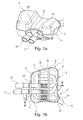
- Fig. 1 is a silencer unit according to the invention designated 1.
- the presentation of the Fig. 1 a and 1 b shows a perspective view of the inventive silencer unit 1.
- Die Fig. 1 b corresponds to the representation of Fig. 1a but with a housing cover lifted from a housing bottom.
- the silencer unit 1 comprises a two-part housing 4 with a respective shell-like first housing part 2, which may be formed as a housing bottom, and with a second housing part 3, which may be formed as a housing cover (in the Fig. 1 b Not shown).
- the first and the second housing part 2, 3 can be made in variants of an austenitic and / or a ferritic material.
- an inlet opening 6 and an outlet opening 5 are provided in the housing 4. Through the inlet opening 6 of the muffler unit 1, a hot gas, in particular an exhaust gas, and sound to be damped be supplied.
- a plurality of transverse walls can be arranged, which can divide the housing 4 for damping the sound entering into the muffler unit 1 sound in several subspaces.
- the arrangement and number of transverse walls many variants are conceivable.
- two transverse walls 7 and 8 are arranged, which separate an interior of the housing 4 into a first, second and third subspace 9, 10, 11.
- the silencer unit 1 also has an outlet bottom 12 and an inlet bottom 13, which in the assembled state are respectively inserted into the outlet opening 5 and the inlet opening 6.
- the outlet bottom 12 according to the exemplary embodiment, two passage openings 14, 15 are provided, through each of which an exhaust pipe 16, 17 can be guided.
- the exhaust tube 16, 17 can be welded to the through holes 14, 15.
- the exhaust pipes 16, 17 are performed within the housing 4 through the transverse walls 7, 8 and form a sound damping structure 18 together with the transverse walls 7, 8.
- a through opening 20 is now also provided, through which a supply pipe 19 is performed.
- the feed tube 19 can be welded to the inlet bottom 13.
- the supply pipe 19 is fixed in the housing 4 to the transverse walls 7, 8 and performed by them.
- the supply pipe 19 is thus also part of the sound damping structure 18.
- the outlet bottom 12 and the inlet bottom 13 are each designed as covers 21 inserted in the outlet opening 5 or in the inlet opening 6. This is for clarification in the following to be explained roughly schematic representation of Fig. 2 shown.
- the Fig. 2 shows in a rough schematic sectional view formed as a bottom second housing part 3, in which the outlet opening 5 is provided.
- the outlet opening 5 of the cover 21 designed as outlet outlet 12 is inserted.
- the outlet bottom 12 has the passage openings 14, 15, through which the discharge pipes 16, 17 are performed.
- the exhaust pipes 16, 17 are welded to the outlet bottom 12, as already explained.
- the outlet opening 5 has an outlet collar 22 which runs around along an outer circumference and which points outwards (arrow A in FIG Fig. 2 ) protrudes.
- the outlet bottom 12 in each case has an outlet bottom collar 23 which is complementary to the outlet collar 22.
- an outer peripheral surface 24 of the outlet bottom collar 23 abuts against an inner circumferential surface 25 of the outlet collar 22.
- the outer peripheral surface 24 with the inner peripheral surface 25 welded.
- the outer peripheral surface 24 may also be welded to an end section 26 of the outlet collar 22 enclosing the outlet opening 5 and the outlet collar 22.
- a corresponding weld is in the Fig.2 denoted by the reference numeral 27.
- FIG. 2 The stable mounting of the outlet bottom 12 formed on the outlet opening 5 as a cover 21 is shown in a roughly schematic manner correspondingly for fastening an inlet floor 13 likewise designed as a cover on the inlet opening 6 (cf. Fig. 1 ) applicable.
- the outlet opening 5 may each be partially provided both in the first and in the second housing part 2, 3, and the inlet opening 6 may each be partially provided both in the first and in the second housing part 2, 3 ,
- the assembly of the silencer unit 1 according to the invention can be substantially simplified.
- the outlet bottom 12 can then be inserted into the outlet opening 5 or the inlet base 13 into the inlet opening 6 before the first housing part 2 is welded to the second housing part 3.
- a wall thickness of the first or / and the second housing part 2, 3 is between 0.8 mm and 3.0 mm, but preferably 1.0 mm.
- the natural frequency of the silencer unit 1 preferably has a first natural frequency of at least 200 Hz, most preferably of at least 300 Hz, in the mounted state.
- the muffler unit 1 of the embodiment may be equipped with an exhaust system for a motor vehicle (in the Fig. 1 and 2 not shown). Such an exhaust system then comprises a fluidically connected to the muffler unit 1 supply line for supplying exhaust gas into the muffler unit 1 and a fluidically connected to the muffler unit 1 discharge line for the removal of exhaust gas from the muffler unit. 1
Landscapes
- Engineering & Computer Science (AREA)
- Chemical & Material Sciences (AREA)
- Combustion & Propulsion (AREA)
- Mechanical Engineering (AREA)
- General Engineering & Computer Science (AREA)
- Exhaust Silencers (AREA)
- Cooling, Air Intake And Gas Exhaust, And Fuel Tank Arrangements In Propulsion Units (AREA)
Abstract
- mit einem zweiteiligen Gehäuse (4) mit einem jeweils schalenartig ausgebildeten ersten und zweiten Gehäuseteil (2, 3),
- wobei in dem Gehäuse (4) eine Auslass- und eine Einlassöffnung (5, 6) vorgesehen ist,
- mit einem Auslassboden (12) und einem Einlassboden (13), welche in die Auslassöffnung (5) bzw. Einlassöffnung (6) eingesetzt sind,
wobei der Auslassboden (12) und der Einlassboden (13) jeweils als in die Auslassöffnung (5) bzw. in die Einlassöffnung (6) einsteckbarer Deckel ausgebildet sind.

Description
- Die vorliegende Erfindung betrifft eine Schalldämpfer-Einheit, insbesondere für ein Kraftfahrzeug. Die vorliegende Erfindung betrifft ferner ein Abgas-System für ein Kraftfahrzeug.
- Herkömmliche Schalldämpfer-Einheiten weisen üblicherweise ein im Wesentlichen rohrförmiges Gehäuse mit einer Oberschale und einer Unterschale auf, das in einem montierten Zustand einen gasdicht geschlossenen Hohlraum ausbildet, wobei an dem Gehäuse ein Auslassrohr und ein Einlassrohr angebracht sind. Derartige Schalldämpfer-Einheiten werden beispielsweise für Brennkraftmaschinen von Kraftfahrzeugen verwendet. In diesem Zusammenhang ist vor allem die Verwendung der Schalldämpfer-Einheit in einem Abgastrakt der Brennkraftmaschine bekannt. In modernen Brennkraftmaschinen kann ein Schalldämpfer zudem in einem Frischlufttrakt oder in einem Ansaugtrakt der Brennkraftmaschineangeordnet sein.
- Aus der
EP 1 691 050 A1 ist ein Schalldämpfer bekannt, welcher ein zweiteiliges Gehäuse mit einem jeweils schalenartig ausgebildeten ersten und zweiten Gehäuseteil umfasst, welches in einem montierten Zustand einen Hohlraum zur Aufnahme eines Gases bildet. Dabei sind in dem Gehäuse eine Auslass- und eine Einlassöffnung vorgesehen, wobei die Einlassöffnung jeweils teilweise sowohl in dem ersten als auch in dem zweiten Gehäuseteil angeordnet ist. Entsprechend ist die Auslassöffnung ebenso jeweils teilweise sowohl in dem ersten als auch in dem zweiten Gehäuseteil vorgesehen. Die Auslass- bzw. Einlassöffnung ist also jeweils zwischen den beiden Gehäuseteilen angeordnet und von beiden Gehäuseteilen teilweise umfasst. Der Schalldämpfer umfasst ferner einen Auslassboden und einen Einlassboden, welche in der Auslassöffnung bzw. Einlassöffnung angebracht sind. Um unterschiedliche Konfigurationen im Hinblick auf Anzahl und Position von Einlassöffnungen zum Zuführen von Gas in den Schalldämpfer zu realisieren, muss nur der Einlassboden adaptiert werden, während das erste und zweite Gehäuseteil unverändert bleiben können. Entsprechendes gilt für den Auslassboden und in diesem angeordnete Auslassöffnungen zur Abführung von Abgas aus der Schalldämpfer-Einheit. Zudem kann durch die Verwendung eines Auslass- bzw. Einlassbodens ein relativ kompliziertes und fehlerträchtiges Verschweißen eines direkt in der Auslass- bzw. Einlassöffnung angeordneten Auslass- bzw. Einlassrohrs mit dem ersten und zweiten Gehäuseteil (also im Bereich der Trennstelle zwischen dem ersten und zweiten Gehäuseteil) vermieden werden. Da durch die Verwendung eines separaten Einlass- bzw. Auslassbodens sog. T-Stöße beim Verschweißen zu größeren Querschnitten verlegt werden, ist die Festigkeit des Gehäuses nach dem Verschweißen der beiden Gehäuseteile besonders hoch. Somit lassen sich relativ preiswert unterschiedliche Schalldämpfer-Typen realisieren, die insbesondere an unterschiedliche Abgasanlagen anpassbar sind. - Die vorliegende Erfindung beschäftigt sich mit dem Problem, eine verbesserte Ausführungsform für einen Schalldämpfer der eingangs genannten Art anzugeben, insbesondere hinsichtlich der Befestigung eines Bodens in einer Öffnung in dem Gehäuse des Schalldämpfers.
- Dieses Problem wird erfindungsgemäß durch eine Schalldämpfer-Einheit gemäß den unabhängigen Patentansprüchen gelöst. Vorteilhafte Ausführungsformen sind Gegenstand der Unteransprüche.
- Die Erfindung beruht auf dem allgemeinen Gedanken, dass der Auslassboden und der Einlassboden jeweils als in die Auslassöffnung bzw. auf die Einlassöffnung einsteckbarer Deckel ausgebildet sind. Dies ermöglicht eine besonders stabile und damit zuverlässige Befestigung des Einlass- bzw. Auslassbodens auf der Einlass- bzw. Auslassöffnung. Erfindungsgemäß lassen sich somit durch die Verwendung von für unterschiedliche Abgasanlagen leicht adaptierbaren Auslass- bzw. Einlassböden relativ preiswert unterschiedliche Bauformen von Schalldämpfer-Einheiten herstellen, wobei gleichzeitig sowohl der Auslassboden als auch der Einlassboden mechanisch sehr stabil und zuverlässig an den Gehäuseteilen befestigt ist. Insbesondere lassen sich erfindungsgemäß verschiedenartige, mechanisch sehr stabile Bauformen von Schalldämpfer-Einheiten im Sinne eines Baukastensystems realisieren.
- Vorzugsweise weisen die Auslassöffnung und die Einlassöffnung jeweils entlang eines Außenumfangs umlaufend einen Auslass-Kragen bzw. einen Einlass-Kragen auf, der jeweils nach außen von dem Gehäuse vorsteht, wobei der Auslassboden und der Einlassboden jeweils einen zu dem Auslass-Kragen bzw. Einlass-Kragen komplementären Auslassboden-Kragen bzw. Einlassboden-Kragen aufweisen. Auf diese Weise kann die mechanische Stabilität und somit auch die Zuverlässigkeit der Befestigung von Auslassboden bzw. Einlassboden in der Auslassöffnung bzw. Einlassöffnung verbessert werden.
- Um die Zuverlässigkeit der Befestigung weiter zu erhöhen, kann gemäß einer weiterbildenden Ausführungsform in einem montierten Zustand der Schalldämpfer-Einheit eine Außenumfangsfläche des Auslassboden-Kragens an einer Innenumfangsfläche des Auslass-Kragens wenigsten teilweise anliegen oder/und eine Außenumfangsfläche des Einlassboden-Kragens an einer Innenumfangsfläche des Einlass-Kragens wenigstens teilweise anliegen.
- In einer weiterbildenden Ausführungsform kann daran gedacht sein, dass in dem montierten Zustand die Außenumfangsfläche des Auslassboden-Kragens mit der Innenumfangsfläche des Auslass-Kragens oder/und mit einem Endabschnitt des Auslass-Kragens verschweißt ist, und dass die Außenumfangsfläche des Einlassboden-Kragens mit der Innenumfangsfläche des Einlass-Kragens oder/und mit einem Endabschnitt des Einlass-Kragens verschweißt ist.
- In einer ebenfalls weiterbildenden Ausführungsform kann der Auslassboden wenigstens eine Durchgangsöffnung aufweisen zur Aufnahme wenigstens eines Auslassrohres oder/und kann der Einlassboden wenigstens eine Durchgangsöffnung aufweisen zur Aufnahme wenigstens eines Einlassrohres. Gemäß dieser Ausführungsform kann sowohl die Anzahl als auch die jeweilige Position der in dem Auslassboden anzuordnenden Auslassrohre bzw. in dem Einlassboden angeordneten Einlassrohre je nach Verwendung der Schalldämpfer-Einheit variiert werden.
- In einer besonders bevorzugten Ausführungsform ist in der wenigstens einen Durchgangsöffnung des Auslassbodens wenigstens ein Auslassrohr, insbesondere mittels Verschweißen, angebracht, oder/und ist in der wenigstens einen Durchgangsöffnung des Einlassbodens wenigstens ein Einlassrohr, insbesondere mittels Verschweißen, angebracht.
- Um den Zusammenbau der erfindungsgemäßen Schalldämpfer-Einheit zu vereinfachen, kann in einer weiteren bevorzugten Ausführungsform die Auslassöffnung jeweils teilweise sowohl in dem ersten als auch in dem zweiten Gehäuseteil vorgesehen sein, wobei die Einlassöffnung jeweils teilweise sowohl in dem ersten als auch in dem zweiten Gehäuseteil vorgesehen sein kann. Somit lassen sich Auslass- bzw. Einlass-Öffnung in das erste Gehäuseteil einsetzen, bevor dieses mit dem zweiten Gehäuseteil verbunden wird.
- In einer besonders bevorzugten Ausführungsform ist das erste oder/und zweite Gehäuseteil aus einem austhentischen oder/und einem ferritischen Werkstoff hergestellt.
- Des Weiteren kann daran gedacht sein, dass bei einer bevorzugten Ausführungsform eine Wandstärke des ersten oder/und des zweiten Gehäuseteils zwischen 0,8 mm und 3,0 mm, vorzugsweise 1,0 mm beträgt. Dies ermöglicht die Herstellung der erfindungsgemäßen Schalldämpfer-Einheit in Leichtbauweise.
- Vorzugsweise ist die Schalldämpfer-Einheit derart ausgebildet, dass sie in einem montierten Zustand eine erste Eigenfrequenz von mindestens 200 Hz, vorzugsweise von mindestens 300 Hz, aufweist. Auf diese Weise ist eine besonders effektive Schalldämpfung mittels der Schalldämpfer-Einheit möglich.
- Die Erfindung betrifft ferner ein Abgassystem für ein Kraftfahrzeug, umfassend eine Schalldämpfer-Einheit mit einem oder mehreren der oben genannten Merkmale, eine mit der Schalldämpfer-Einheit fluidisch verbundene Zuführungsleitung zur Zuführung von Abgas in die Schalldämpfer-Einheit und eine mit der Schalldämpfer-Einheit fluidisch verbundene Abführungsleitung zur Abführung von Abgas aus der Schalldämpfer-Einheit.
- Weitere wichtige Merkmale und Vorteile der Erfindung ergeben sich aus den Unteransprüchen, aus den Zeichnungen und das der zugehörigen Figurenbeschreibung anhand der Zeichnungen.
- Es versteht sich, dass die vorstehend genannten und die nachstehend noch zu erläuternden Merkmale nicht nur in der jeweils angegebenen Kombination, sondern auch in anderen Kombinationen oder in Alleinstellung verwendbar sind, ohne den Rahmen der Erfindung zu verlassen.
- Bevorzugte Ausführungsbeispiele der Erfindung sind in den Zeichnungen dargestellt und werden in der nachfolgenden Beschreibung näher erläutert, wobei sich gleiche Bezugszeichen auf gleiche oder ähnliche oder funktional gleiche Bauteile beziehen.
- Dabei zeigen jeweils schematisch:
- Fig. 1
- ein Ausführungsbeispiel einer eine erfindungsgemäßen Schalldämpfer-Einheit,
- Fig. 2
- eine grobschematische Teilansicht der Schalldämpfer-Einheit der
Fig. 1 . - In der
Fig. 1 ist eine erfindungsgemäße Schalldämpfer-Einheit mit 1 bezeichnet. Die Darstellung derFig. 1 a und 1 b zeigt dabei eine perspektivische Ansicht auf die erfindungsgemäße Schalldämpfer-Einheit 1. DieFig. 1 b entspricht der Darstellung derFig. 1a , jedoch mit einem von einem Gehäuse-Boden abgehobenen Gehäuse-Deckel. - Die erfindungsgemäße Schalldämpfer-Einheit 1 umfasst ein zweiteiliges Gehäuse 4 mit einem jeweils schalenartig ausgebildeten ersten Gehäuseteil 2, welches als Gehäuse-Boden ausgebildet sein kann, und mit einem zweiten Gehäuseteil 3, welches als Gehäuse-Deckel ausgebildet sein kann (in der
Fig. 1 b nicht gezeigt). Das erste und das zweite Gehäuseteil 2, 3 können dabei in Varianten aus einem austhenitischen oder/und einem ferritischen Werkstoff hergestellt sein. In dem Gehäuse 4 sind eine Einlassöffnung 6 und eine Auslassöffnung 5 vorgesehen. Durch die Einlassöffnung 6 kann der Schalldämpfer-Einheit 1 ein heißes Gas, insbesondere ein Abgas, und zu bedämpfender Schall zugeführt werden. - In dem Gehäuse 4 können mehrere Querwände angeordnet sein, welche das Gehäuse 4 zur Dämpfung des in die Schalldämpfer-Einheit 1 eintretenden Schalls in mehrere Teilräume aufteilen können. Hinsichtlich der Anordnung und Anzahl der Querwände sind vielerlei Varianten vorstellbar. In dem Ausführungsbeispiel der
Figur 1 sind exemplarisch zwei Querwände 7 und 8 angeordnet, welche einen Innenraum des Gehäuses 4 in einen ersten, zweiten und dritten Teilraum 9, 10, 11 abtrennen. - Die erfindungsgemäße Schalldämpfer-Einheit 1 weist zudem einen Auslassboden 12 und einen Einlassboden 13 auf, welche im montierten Zustand jeweils in die Auslassöffnung 5 bzw. Einlassöffnung 6 eingesetzt sind. In dem Auslassboden 12 gemäß dem Ausführungsbeispiel sind zwei Durchgangsöffnungen 14, 15 bereitgestellt, durch welche jeweils ein Abführungsrohr 16, 17 geführt sein kann. Die Abführungsröhre 16, 17 können dabei mit den Durchgangsöffnungen 14, 15 verschweißt sein.
- In dem Ausführungsbeispiel sind die Abführungsrohre 16, 17 innerhalb des Gehäuses 4 durch die Querwände 7, 8 durchgeführt und bilden gemeinsam mit den Querwänden 7, 8 eine Schalldämpfungsstruktur 18 aus.
- In dem Einlassboden 13 ist nun ebenfalls eine Durchgangsöffnung 20 bereitgestellt, durch welche ein Zuführungsrohr 19 durchgeführt ist. Das Zuführungsrohr 19 kann dabei mit dem Einlassboden 13 verschweißt sein. Das Zuführungsrohr 19 ist in dem Gehäuse 4 an den Querwänden 7, 8 befestigt und durch diese durchgeführt. Das Zuführungsrohr 19 ist somit auch Teil der Schalldämpfungsstruktur 18.
- Es ist klar, dass hinsichtlich der konkreten technischen Realisierung der Schalldämpfungsstruktur 18 zahlreiche Varianten, insbesondere hinsichtlich einer Anzahl an Querwänden, deren Anordnung in dem Gehäuse 4 und auch hinsichtlich der Anordnung und Befestigung von Zuführungs- und Abführungsrohren in dem Gehäuse 4 möglich sind. Es ist ebenso klar, dass in Varianten sowohl die Anzahl der Zuführungsrohre als auch deren jeweilige Position in dem Auslassboden 12 variieren können. Entsprechendes gilt mutatis mutandis für Anzahl und Position der Abführungsrohre in dem Einlassboden 13.
- Erfindungsgemäß sind nun der Auslassboden 12 und der Einlassboden 13 jeweils als in die Auslassöffnung 5 bzw. in die Einlassöffnung 6 eingesetzter Deckel 21 ausgebildet. Dies ist zur Verdeutlichung in der im Folgenden zu erläuternden grobschematischen Darstellung der
Fig. 2 gezeigt. - Die
Fig. 2 zeigt in einer grobschematischen Schnittansicht das als Boden ausgebildete zweite Gehäuseteil 3, in welchem die Auslassöffnung 5 vorgesehen ist. In die Auslassöffnung 5 ist der als Deckel 21 ausgebildete Auslassboden 12 eingesteckt. Der Auslassboden 12 weist die Durchgangsöffnungen 14, 15 auf, durch welche die Abführungsrohre 16, 17 durchgeführt sind. Die Abführungsrohre 16, 17 sind dabei mit dem Auslassboden 12, wie bereits erläutert, verschweißt. Die Auslassöffnung 5 weist einen entlang eines Außenumfangs umlaufenden Auslass-Kragen 22 auf, der nach außen (Pfeil A in derFig. 2 ) vorsteht. Entsprechend weist der Auslassboden 12 jeweils einen zu dem Auslass-Kragen 22 komplementären Auslassboden-Kragen 23 auf. - In dem in der
Fig. 2 gezeigten montierten Zustand des Auslassbodens 12 liegt eine Außenumfangsfläche 24 der Auslassboden-Kragens 23 an einer Innenumfangsfläche 25 des Auslass-Kragens 22 an. Zur stabilen Befestigung des Deckels 21 an dem Gehäuse 4 kann die Außenumfangsfläche 24 mit der Innenumfangsfläche 25 verschweißt sein. Alternativ oder zusätzlich kann die Außenumfangsfläche 24 auch mit einem die Auslassöffnung 5 und den Auslass-Kragen 22 einfassenden Endabschnitt 26 des Auslass-Kragens 22 verschweißt sein. Eine entsprechende Schweißnaht ist in derFig.2 mit dem Bezugszeichen 27 bezeichnet. - Die Erläuterungen bzgl. der in der
Figur 2 grobschematisch dargestellten stabilen Befestigung des als Deckel 21 ausgebildeten Auslassbodens 12 auf der Auslassöffnung 5 sind entsprechend für eine Befestigung eines ebenfalls als Deckel ausgebildeten Einlassbodens 13 auf der Einlassöffnung 6 (vgl.Fig. 1 ) anwendbar. - In einer bevorzugten Variante des Ausführungsbeispiels kann die Auslassöffnung 5 jeweils teilweise sowohl in dem ersten als auch in dem zweiten Gehäuseteil 2, 3 vorgesehen sein, und kann die Einlassöffnung 6 jeweils teilweise sowohl in dem ersten als auch in dem zweiten Gehäuseteil 2, 3 vorgesehen sein. Auf diese Weise kann die Montage der erfindungsgemäßen Schalldämpfer-Einheit 1 wesentlich vereinfacht werden. Für die Montage der Schalldämpfer-Einheit 1 können dann vor einem Verschweißen des ersten Gehäuseteils 2 mit dem zweiten Gehäuseteil 3 der Auslassboden 12 in die Auslassöffnung 5 bzw. der Einlassboden 13 in die Einlassöffnung 6 eingesetzt werden.
- In bevorzugten Varianten des Ausführungsbeispiels beträgt eine Wandstärke des ersten oder/und des zweiten Gehäuseteils 2, 3 zwischen 0,8 mm und 3,0 mm, vorzugsweise jedoch 1,0 mm. Die Eigenfrequenz der Schalldämpfer-Einheit 1 weist vorzugsweise in dem montierten Zustand eine erste Eigenfrequenz von mindestens 200 Hz, höchst vorzugsweise von mindestens 300 Hz, auf. Die Schalldämpfer-Einheit 1 des Ausführungsbeispiels kann mit einem Abgas-System für ein Kraftfahrzeug (in den
Fig. 1 und2 nicht gezeigt) verbunden sein. Ein solches Abgassystem umfasst dann eine mit der Schalldämpfer-Einheit 1 fluidisch verbundene Zuführungsleitung zur Zuführung von Abgas in die Schalldämpfer-Einheit 1 und eine mit der Schalldämpfer-Einheit 1 fluidisch verbundene Abführungsleitung zur Abführung von Abgas aus der Schalldämpfer-Einheit 1.
Claims (11)
- Schalldämpfer-Einheit (1), insbesondere für ein Kraftfahrzeug,- mit einem zweiteiliges Gehäuse (4) mit einem jeweils schalenartig ausgebildeten ersten und zweiten Gehäuseteil (2, 3),- wobei in dem Gehäuse (4) eine Auslass- und eine Einlassöffnung (5, 6) vorgesehen ist,- mit einem Auslassboden (12) und einem Einlassboden (13), welche in die Auslassöffnung (5) bzw. Einlassöffnung (6) eingesetzt sind,
dadurch gekennzeichnet, dass der Auslassboden (12) und der Einlassboden (13) jeweils als in die Auslassöffnung (5) bzw. in die Einlassöffnung (6) einsteckbarer Deckel ausgebildet sind. - Schalldämpfer-Einheit (1) nach Anspruch 1,
dadurch gekennzeichnet, dass- die Auslassöffnung (5) und die Einlassöffnung (6) jeweils entlang eines Außenumfangs umlaufend einen Auslass-Kragen (22) bzw. einen Einlass-Kragen aufweisen, der jeweils nach außen von dem Gehäuse (4) vorsteht,- der Auslassboden (12) und der Einlassboden (13) jeweils einen zu dem Auslass-Kragen (22) bzw. Einlass-Kragen komplementären Auslassboden-Kragen (23) bzw. Einlassboden-Kragen aufweisen. - Schalldämpfer-Einheit (1) nach Anspruch 2,
dadurch gekennzeichnet, dass
in einem montierten Zustand der Schalldämpfer-Einheit- eine Außenumfangsfläche (24) des Auslassboden-Kragens (23) an einer Innenumfangsfläche (25) des Auslass-Kragens (22) wenigstens teilweise anliegt, und- eine Außenumfangsfläche des Einlassboden-Kragens an einer Innenumfangsfläche des Einlass-Kragens wenigstens teilweise anliegt. - Schalldämpfer-Einheit (1) nach Anspruch 3,
dadurch gekennzeichnet, dass
in dem montierten Zustand- die Außenumfangsfläche (24) des Auslassboden-Kragens (23) mit der Innenumfangsfläche (25) des Auslass-Kragens (22) oder/und mit einem Endabschnitt des Auslass-Kragens (22) verschweißt ist, und- die Außenumfangsfläche des Einlassboden-Kragens mit der Innenumfangsfläche des Einlass-Kragens oder/und mit einem Endabschnitt des Einlass-Kragens verschweißt ist. - Schalldämpfer-Einheit (1) nach einem der vorhergehenden Ansprüche,
dadurch gekennzeichnet, dass- der Auslassboden (12) wenigstens eine Durchgangsöffnung (14, 15) aufweist zur Aufnahme wenigstens eines Auslassrohrs (16, 17), oder/und dass- der Einlassboden (13) wenigstens eine Durchgangsöffnung (20) aufweist zur Aufnahme wenigstens eines Einlassrohrs (19). - Schalldämpfer-Einheit (1) nach einem der vorhergehenden Ansprüche,
dadurch gekennzeichnet, dass- in der wenigstens einen Durchgangsöffnung (14, 15) des Auslassbodens (12) wenigstens ein Auslassrohr (16, 17), insbesondere mittels Verschweißen, angebracht ist, oder/und dass- in der wenigstens einen Durchgangsöffnung (20) des Einlassbodens (13) wenigstens ein Einlassrohr, insbesondere mittels Verschweißen, angebracht ist. - Schalldämpfer-Einheit (1) nach einem der vorhergehenden Ansprüche,
dadurch gekennzeichnet, dass- die Auslassöffnung (5) jeweils teilweise sowohl in dem ersten als auch in dem zweiten Gehäuseteil (2, 3) vorgesehen ist,- die Einlassöffnung (6) jeweils teilweise sowohl in dem ersten als auch in dem zweiten Gehäuseteil (2, 3) vorgesehen ist. - Schalldämpfer-Einheit (1) nach einem der vorhergehenden Ansprüche,
dadurch gekennzeichnet, dass
das erste oder/und zweite das Gehäuseteil (2, 3) aus einem austhentischen oder/und ferritischen Werkstoff hergestellt ist. - Schalldämpfer-Einheit (1) nach einem der vorhergehenden Ansprüche,
dadurch gekennzeichnet, dass
eine Wandstärke des ersten oder/und des zweiten Gehäuseteils (2, 3) zwischen 0,8 mm und 3,0 mm, vorzugsweise 1,0 mm, beträgt. - Schalldämpfer-Einheit (1) nach einem der vorhergehenden Ansprüche,
dadurch gekennzeichnet, dass
die Schalldämpfer-Einheit (1) derart ausgebildet ist, dass sie in einem montierten Zustand eine erste Eigenfrequenz von mindestens 200 Hz, vorzugsweise von mindestens 300 Hz, aufweist. - Abgas-System für ein Kraftfahrzeug, umfassend:- eine Schalldämpfer-Einheit (1) nach einem der vorhergehenden Ansprüche,- eine mit der Schalldämpfer-Einheit (1) fluidisch verbundene Zuführungsleitung zur Zuführung von Abgas in die Schalldämpfer-Einheit (1),- eine mit der Schalldämpfer-Einheit (1) fluidisch verbundene Abführungsleitung zur Abführung von Abgas aus der Schalldämpfer-Einheit (1).
Applications Claiming Priority (1)
| Application Number | Priority Date | Filing Date | Title |
|---|---|---|---|
| DE102012204114.1A DE102012204114B4 (de) | 2012-03-15 | 2012-03-15 | Schalldämpfer-Einheit |
Publications (2)
| Publication Number | Publication Date |
|---|---|
| EP2639423A1 true EP2639423A1 (de) | 2013-09-18 |
| EP2639423B1 EP2639423B1 (de) | 2016-06-22 |
Family
ID=47748500
Family Applications (1)
| Application Number | Title | Priority Date | Filing Date |
|---|---|---|---|
| EP13156077.3A Revoked EP2639423B1 (de) | 2012-03-15 | 2013-02-21 | Schalldämpfer-einheit |
Country Status (5)
| Country | Link |
|---|---|
| US (1) | US8939254B2 (de) |
| EP (1) | EP2639423B1 (de) |
| JP (1) | JP2013194736A (de) |
| CN (1) | CN103410597B (de) |
| DE (1) | DE102012204114B4 (de) |
Families Citing this family (5)
| Publication number | Priority date | Publication date | Assignee | Title |
|---|---|---|---|---|
| US8827035B2 (en) * | 2012-12-03 | 2014-09-09 | Ford Global Technologies, Llc | Conformal transverse muffler |
| CN104832259B (zh) * | 2014-05-28 | 2018-12-25 | 北汽福田汽车股份有限公司 | 用于汽车的消声器及具有其的汽车 |
| EP3436752B1 (de) | 2016-03-30 | 2021-06-30 | Marine Canada Acquisition Inc. | Fahrzeugheizgerät und steuerungen dafür |
| DE102016123114A1 (de) * | 2016-11-30 | 2018-05-30 | Dr. Ing. H.C. F. Porsche Aktiengesellschaft | Fahrzeugkomponente |
| US10787951B2 (en) | 2017-11-20 | 2020-09-29 | Tenneco Automotive Operating Company Inc. | Pipe and metal sheet subassembly for an exhaust treatment device |
Citations (4)
| Publication number | Priority date | Publication date | Assignee | Title |
|---|---|---|---|---|
| EP0337877A1 (de) * | 1988-04-12 | 1989-10-18 | Regie Nationale Des Usines Renault | Schalldämpfer für Explosionsmotoren |
| US4993513A (en) * | 1988-01-29 | 1991-02-19 | Honda Giken Kogyo Kabushiki Kaisha | Muffler |
| EP1691050A1 (de) | 2005-01-17 | 2006-08-16 | J. Eberspächer GmbH & Co. KG | Schalldämpfer |
| WO2008073137A1 (en) * | 2006-12-14 | 2008-06-19 | Ocv Intellectual Capital, Llc | Long fiber thermoplastic composite muffler system with integrated reflective chamber |
Family Cites Families (21)
| Publication number | Priority date | Publication date | Assignee | Title |
|---|---|---|---|---|
| DE3101252A1 (de) | 1981-01-16 | 1982-09-02 | Alcan Aluminiumwerke GmbH, 3400 Göttingen | Abgasschalldaempfer fuer brennkraftmaschinen und verfahren zu dessen herstellung |
| JPS5930516U (ja) * | 1982-08-20 | 1984-02-25 | トヨタ自動車株式会社 | 車両用分割式マフラ装置 |
| JPS6117411U (ja) * | 1984-07-06 | 1986-01-31 | 本田技研工業株式会社 | 消音器 |
| US4909348A (en) * | 1988-01-20 | 1990-03-20 | Ap Parts Manufacturing Company | Stamp formed exhaust muffler with conformal outer shell |
| US4821840A (en) * | 1988-01-20 | 1989-04-18 | Ap Parts Manufacturing Company | Stamp formed exhaust muffler with conformal outer shell |
| JPH072971Y2 (ja) * | 1988-01-29 | 1995-01-30 | 本田技研工業株式会社 | 消音器 |
| US4905791A (en) * | 1989-01-23 | 1990-03-06 | Ap Parts Manufacturing Company | Light weight hybrid exhaust muffler and method of manufacture |
| US5004069A (en) * | 1990-01-26 | 1991-04-02 | Ap Parts Manufacturing Company | Stamp formed muffler with transverse baffle tube |
| US4958701A (en) * | 1990-03-26 | 1990-09-25 | Ap Parts Manufacturing Company | Stamp formed muffler with pocket-free baffle crease |
| US5428194A (en) * | 1993-10-19 | 1995-06-27 | Ap Parts Manufacturing Company | Narrow width stamp formed muffler |
| JP3656917B2 (ja) | 1994-06-11 | 2005-06-08 | 本田技研工業株式会社 | 車両用排気装置のスパークアレスター装置 |
| US5739484A (en) | 1997-03-12 | 1998-04-14 | Jones; Mack L. | Exhaust muffler |
| US6135237A (en) * | 1998-04-03 | 2000-10-24 | Arvin Industries, Inc. | Stamp-formed muffler |
| EP1061240A3 (de) | 1999-06-17 | 2002-12-11 | Scambia Industrial Developments Aktiengesellschaft | Verfahren zum Verbinden von Verbindungsabschnitten einer Abgasanlage sowie Abgasanlage |
| DE10060522B4 (de) * | 2000-12-06 | 2004-07-22 | J. Eberspächer GmbH & Co. KG | Abgas-Schalldämpfer für ein brennstoffbetriebenes Heizgerät |
| US20030129102A1 (en) | 2002-01-08 | 2003-07-10 | Turek Alan Gerard | Exhaust emissions control devices comprising adhesive |
| DE102005017946B4 (de) | 2005-04-18 | 2007-11-22 | J. Eberspächer GmbH & Co. KG | Abgasbehandlungsvorrichtung und zugehörige Abgasanlage |
| DE102005017947A1 (de) | 2005-04-18 | 2006-10-19 | J. Eberspächer GmbH & Co. KG | Abgasbehandlungsvorrichtung für eine Abgasanlage |
| US7730996B2 (en) * | 2006-04-12 | 2010-06-08 | Ocv Intellectual Capital, Llc | Long fiber thermoplastic composite muffler system with integrated crash management |
| JP2009243388A (ja) * | 2008-03-31 | 2009-10-22 | Sankei Kogyo Kk | マフラーの製造方法 |
| DE102009013222B3 (de) | 2009-03-17 | 2010-03-11 | Kwh Automobiltechnik Gmbh | Hohlkörper und Verfahren seiner Herstellung |
-
2012
- 2012-03-15 DE DE102012204114.1A patent/DE102012204114B4/de active Active
-
2013
- 2013-02-21 EP EP13156077.3A patent/EP2639423B1/de not_active Revoked
- 2013-03-12 CN CN201310118926.6A patent/CN103410597B/zh active Active
- 2013-03-15 US US13/835,796 patent/US8939254B2/en active Active
- 2013-03-15 JP JP2013053219A patent/JP2013194736A/ja not_active Ceased
Patent Citations (4)
| Publication number | Priority date | Publication date | Assignee | Title |
|---|---|---|---|---|
| US4993513A (en) * | 1988-01-29 | 1991-02-19 | Honda Giken Kogyo Kabushiki Kaisha | Muffler |
| EP0337877A1 (de) * | 1988-04-12 | 1989-10-18 | Regie Nationale Des Usines Renault | Schalldämpfer für Explosionsmotoren |
| EP1691050A1 (de) | 2005-01-17 | 2006-08-16 | J. Eberspächer GmbH & Co. KG | Schalldämpfer |
| WO2008073137A1 (en) * | 2006-12-14 | 2008-06-19 | Ocv Intellectual Capital, Llc | Long fiber thermoplastic composite muffler system with integrated reflective chamber |
Also Published As
| Publication number | Publication date |
|---|---|
| DE102012204114B4 (de) | 2015-03-26 |
| US20130240289A1 (en) | 2013-09-19 |
| DE102012204114A1 (de) | 2013-09-19 |
| CN103410597A (zh) | 2013-11-27 |
| US8939254B2 (en) | 2015-01-27 |
| JP2013194736A (ja) | 2013-09-30 |
| CN103410597B (zh) | 2016-12-28 |
| EP2639423B1 (de) | 2016-06-22 |
Similar Documents
| Publication | Publication Date | Title |
|---|---|---|
| EP2354483B1 (de) | Schalldämpfer | |
| EP2718550B1 (de) | Schalldämpfer und herstellungsverfahren | |
| EP2639423B1 (de) | Schalldämpfer-einheit | |
| DE102009035738A1 (de) | Fahrzeugschalldämpfer | |
| DE102019210078A1 (de) | Luftfiltermodul | |
| EP3009623B1 (de) | Komponente einer abgasanlage und halterung für diese komponente | |
| EP1843018A1 (de) | Schalldämpfer | |
| EP3061931B1 (de) | Abgasführungssystem für eine brennkraftmaschine | |
| EP3245396B1 (de) | Fahrzeugschalldämpfer | |
| EP3330509B1 (de) | Abgasschalldämpfer und verfahren zu dessen herstellung | |
| EP2643569B1 (de) | Schalldämpfer | |
| DE102014110101A1 (de) | Schalldämpfer | |
| DE10300384B4 (de) | Abgasanlage | |
| EP2007974B2 (de) | Schalldämpfer für eine abgasanlage | |
| DE102012207198B4 (de) | Vorrichtung zur Verringerung der Lärmemission von Luftansaugrohren | |
| DE102021115962A1 (de) | Schalldämpfer und Verfahren zur Herstellung eines Schalldämpfers | |
| EP3587754B1 (de) | Schalldämpfer | |
| EP3770396B1 (de) | Abgasnachbehandlungsvorrichtung für eine abgasanlage eines kraftfahrzeugs sowie kraftfahrzeug mit einer derartigen abgasnachbehandlungsvorrichtung | |
| EP4105456B1 (de) | Schalldämpfer für eine abgasanlage einer brennkraftmaschine | |
| DE102009018957A1 (de) | Schalldämpfer für eine Abgasanlage | |
| EP1691050B1 (de) | Schalldämpfer | |
| EP4538507A1 (de) | Schalldämpfer | |
| EP4112892A1 (de) | Schalldämpfer |
Legal Events
| Date | Code | Title | Description |
|---|---|---|---|
| PUAI | Public reference made under article 153(3) epc to a published international application that has entered the european phase |
Free format text: ORIGINAL CODE: 0009012 |
|
| AK | Designated contracting states |
Kind code of ref document: A1 Designated state(s): AL AT BE BG CH CY CZ DE DK EE ES FI FR GB GR HR HU IE IS IT LI LT LU LV MC MK MT NL NO PL PT RO RS SE SI SK SM TR |
|
| AX | Request for extension of the european patent |
Extension state: BA ME |
|
| 17P | Request for examination filed |
Effective date: 20131028 |
|
| RBV | Designated contracting states (corrected) |
Designated state(s): AL AT BE BG CH CY CZ DE DK EE ES FI FR GB GR HR HU IE IS IT LI LT LU LV MC MK MT NL NO PL PT RO RS SE SI SK SM TR |
|
| RAP1 | Party data changed (applicant data changed or rights of an application transferred) |
Owner name: EBERSPAECHER EXHAUST TECHNOLOGY GMBH & CO. KG |
|
| 17Q | First examination report despatched |
Effective date: 20150624 |
|
| GRAP | Despatch of communication of intention to grant a patent |
Free format text: ORIGINAL CODE: EPIDOSNIGR1 |
|
| RIC1 | Information provided on ipc code assigned before grant |
Ipc: F01N 13/18 20100101AFI20160111BHEP Ipc: F01N 1/08 20060101ALI20160111BHEP Ipc: F01N 13/08 20100101ALI20160111BHEP |
|
| INTG | Intention to grant announced |
Effective date: 20160212 |
|
| GRAS | Grant fee paid |
Free format text: ORIGINAL CODE: EPIDOSNIGR3 |
|
| GRAA | (expected) grant |
Free format text: ORIGINAL CODE: 0009210 |
|
| AK | Designated contracting states |
Kind code of ref document: B1 Designated state(s): AL AT BE BG CH CY CZ DE DK EE ES FI FR GB GR HR HU IE IS IT LI LT LU LV MC MK MT NL NO PL PT RO RS SE SI SK SM TR |
|
| REG | Reference to a national code |
Ref country code: GB Ref legal event code: FG4D Free format text: NOT ENGLISH |
|
| REG | Reference to a national code |
Ref country code: CH Ref legal event code: EP |
|
| REG | Reference to a national code |
Ref country code: IE Ref legal event code: FG4D Free format text: LANGUAGE OF EP DOCUMENT: GERMAN |
|
| REG | Reference to a national code |
Ref country code: AT Ref legal event code: REF Ref document number: 807802 Country of ref document: AT Kind code of ref document: T Effective date: 20160715 |
|
| REG | Reference to a national code |
Ref country code: DE Ref legal event code: R096 Ref document number: 502013003438 Country of ref document: DE |
|
| REG | Reference to a national code |
Ref country code: SE Ref legal event code: TRGR |
|
| REG | Reference to a national code |
Ref country code: LT Ref legal event code: MG4D |
|
| REG | Reference to a national code |
Ref country code: NL Ref legal event code: MP Effective date: 20160622 |
|
| PG25 | Lapsed in a contracting state [announced via postgrant information from national office to epo] |
Ref country code: FI Free format text: LAPSE BECAUSE OF FAILURE TO SUBMIT A TRANSLATION OF THE DESCRIPTION OR TO PAY THE FEE WITHIN THE PRESCRIBED TIME-LIMIT Effective date: 20160622 Ref country code: NO Free format text: LAPSE BECAUSE OF FAILURE TO SUBMIT A TRANSLATION OF THE DESCRIPTION OR TO PAY THE FEE WITHIN THE PRESCRIBED TIME-LIMIT Effective date: 20160922 Ref country code: LT Free format text: LAPSE BECAUSE OF FAILURE TO SUBMIT A TRANSLATION OF THE DESCRIPTION OR TO PAY THE FEE WITHIN THE PRESCRIBED TIME-LIMIT Effective date: 20160622 |
|
| PG25 | Lapsed in a contracting state [announced via postgrant information from national office to epo] |
Ref country code: LV Free format text: LAPSE BECAUSE OF FAILURE TO SUBMIT A TRANSLATION OF THE DESCRIPTION OR TO PAY THE FEE WITHIN THE PRESCRIBED TIME-LIMIT Effective date: 20160622 Ref country code: GR Free format text: LAPSE BECAUSE OF FAILURE TO SUBMIT A TRANSLATION OF THE DESCRIPTION OR TO PAY THE FEE WITHIN THE PRESCRIBED TIME-LIMIT Effective date: 20160923 Ref country code: NL Free format text: LAPSE BECAUSE OF FAILURE TO SUBMIT A TRANSLATION OF THE DESCRIPTION OR TO PAY THE FEE WITHIN THE PRESCRIBED TIME-LIMIT Effective date: 20160622 Ref country code: HR Free format text: LAPSE BECAUSE OF FAILURE TO SUBMIT A TRANSLATION OF THE DESCRIPTION OR TO PAY THE FEE WITHIN THE PRESCRIBED TIME-LIMIT Effective date: 20160622 Ref country code: RS Free format text: LAPSE BECAUSE OF FAILURE TO SUBMIT A TRANSLATION OF THE DESCRIPTION OR TO PAY THE FEE WITHIN THE PRESCRIBED TIME-LIMIT Effective date: 20160622 |
|
| PG25 | Lapsed in a contracting state [announced via postgrant information from national office to epo] |
Ref country code: IS Free format text: LAPSE BECAUSE OF FAILURE TO SUBMIT A TRANSLATION OF THE DESCRIPTION OR TO PAY THE FEE WITHIN THE PRESCRIBED TIME-LIMIT Effective date: 20161022 Ref country code: CZ Free format text: LAPSE BECAUSE OF FAILURE TO SUBMIT A TRANSLATION OF THE DESCRIPTION OR TO PAY THE FEE WITHIN THE PRESCRIBED TIME-LIMIT Effective date: 20160622 Ref country code: EE Free format text: LAPSE BECAUSE OF FAILURE TO SUBMIT A TRANSLATION OF THE DESCRIPTION OR TO PAY THE FEE WITHIN THE PRESCRIBED TIME-LIMIT Effective date: 20160622 Ref country code: SK Free format text: LAPSE BECAUSE OF FAILURE TO SUBMIT A TRANSLATION OF THE DESCRIPTION OR TO PAY THE FEE WITHIN THE PRESCRIBED TIME-LIMIT Effective date: 20160622 Ref country code: RO Free format text: LAPSE BECAUSE OF FAILURE TO SUBMIT A TRANSLATION OF THE DESCRIPTION OR TO PAY THE FEE WITHIN THE PRESCRIBED TIME-LIMIT Effective date: 20160622 |
|
| REG | Reference to a national code |
Ref country code: FR Ref legal event code: PLFP Year of fee payment: 5 |
|
| PG25 | Lapsed in a contracting state [announced via postgrant information from national office to epo] |
Ref country code: PL Free format text: LAPSE BECAUSE OF FAILURE TO SUBMIT A TRANSLATION OF THE DESCRIPTION OR TO PAY THE FEE WITHIN THE PRESCRIBED TIME-LIMIT Effective date: 20160622 Ref country code: ES Free format text: LAPSE BECAUSE OF FAILURE TO SUBMIT A TRANSLATION OF THE DESCRIPTION OR TO PAY THE FEE WITHIN THE PRESCRIBED TIME-LIMIT Effective date: 20160622 Ref country code: PT Free format text: LAPSE BECAUSE OF FAILURE TO SUBMIT A TRANSLATION OF THE DESCRIPTION OR TO PAY THE FEE WITHIN THE PRESCRIBED TIME-LIMIT Effective date: 20161024 Ref country code: SM Free format text: LAPSE BECAUSE OF FAILURE TO SUBMIT A TRANSLATION OF THE DESCRIPTION OR TO PAY THE FEE WITHIN THE PRESCRIBED TIME-LIMIT Effective date: 20160622 |
|
| REG | Reference to a national code |
Ref country code: DE Ref legal event code: R026 Ref document number: 502013003438 Country of ref document: DE |
|
| PLBI | Opposition filed |
Free format text: ORIGINAL CODE: 0009260 |
|
| PLBI | Opposition filed |
Free format text: ORIGINAL CODE: 0009260 |
|
| 26 | Opposition filed |
Opponent name: TENNECO GMBH Effective date: 20170322 |
|
| PLAX | Notice of opposition and request to file observation + time limit sent |
Free format text: ORIGINAL CODE: EPIDOSNOBS2 |
|
| 26 | Opposition filed |
Opponent name: FAURECIA EMISSIONS CONTROL TECHNOLOGIES, GERMANY G Effective date: 20170322 |
|
| PG25 | Lapsed in a contracting state [announced via postgrant information from national office to epo] |
Ref country code: BE Free format text: LAPSE BECAUSE OF NON-PAYMENT OF DUE FEES Effective date: 20170228 Ref country code: DK Free format text: LAPSE BECAUSE OF FAILURE TO SUBMIT A TRANSLATION OF THE DESCRIPTION OR TO PAY THE FEE WITHIN THE PRESCRIBED TIME-LIMIT Effective date: 20160622 |
|
| PG25 | Lapsed in a contracting state [announced via postgrant information from national office to epo] |
Ref country code: SI Free format text: LAPSE BECAUSE OF FAILURE TO SUBMIT A TRANSLATION OF THE DESCRIPTION OR TO PAY THE FEE WITHIN THE PRESCRIBED TIME-LIMIT Effective date: 20160622 |
|
| PLBB | Reply of patent proprietor to notice(s) of opposition received |
Free format text: ORIGINAL CODE: EPIDOSNOBS3 |
|
| PG25 | Lapsed in a contracting state [announced via postgrant information from national office to epo] |
Ref country code: MC Free format text: LAPSE BECAUSE OF FAILURE TO SUBMIT A TRANSLATION OF THE DESCRIPTION OR TO PAY THE FEE WITHIN THE PRESCRIBED TIME-LIMIT Effective date: 20160622 |
|
| REG | Reference to a national code |
Ref country code: CH Ref legal event code: PL |
|
| PG25 | Lapsed in a contracting state [announced via postgrant information from national office to epo] |
Ref country code: CH Free format text: LAPSE BECAUSE OF NON-PAYMENT OF DUE FEES Effective date: 20170228 Ref country code: LI Free format text: LAPSE BECAUSE OF NON-PAYMENT OF DUE FEES Effective date: 20170228 |
|
| REG | Reference to a national code |
Ref country code: IE Ref legal event code: MM4A |
|
| PG25 | Lapsed in a contracting state [announced via postgrant information from national office to epo] |
Ref country code: LU Free format text: LAPSE BECAUSE OF NON-PAYMENT OF DUE FEES Effective date: 20170221 |
|
| REG | Reference to a national code |
Ref country code: BE Ref legal event code: MM Effective date: 20170228 |
|
| REG | Reference to a national code |
Ref country code: FR Ref legal event code: PLFP Year of fee payment: 6 |
|
| PG25 | Lapsed in a contracting state [announced via postgrant information from national office to epo] |
Ref country code: IE Free format text: LAPSE BECAUSE OF NON-PAYMENT OF DUE FEES Effective date: 20170221 |
|
| PGFP | Annual fee paid to national office [announced via postgrant information from national office to epo] |
Ref country code: IT Payment date: 20180221 Year of fee payment: 6 |
|
| RIN2 | Information on inventor provided after grant (corrected) |
Inventor name: SCHMITT, MARKUS Inventor name: SCHMIDT, MICHAEL Inventor name: BUCK, HANS-LUDWIG |
|
| PG25 | Lapsed in a contracting state [announced via postgrant information from national office to epo] |
Ref country code: MT Free format text: LAPSE BECAUSE OF FAILURE TO SUBMIT A TRANSLATION OF THE DESCRIPTION OR TO PAY THE FEE WITHIN THE PRESCRIBED TIME-LIMIT Effective date: 20160622 |
|
| PG25 | Lapsed in a contracting state [announced via postgrant information from national office to epo] |
Ref country code: AL Free format text: LAPSE BECAUSE OF FAILURE TO SUBMIT A TRANSLATION OF THE DESCRIPTION OR TO PAY THE FEE WITHIN THE PRESCRIBED TIME-LIMIT Effective date: 20160622 |
|
| RDAF | Communication despatched that patent is revoked |
Free format text: ORIGINAL CODE: EPIDOSNREV1 |
|
| STAA | Information on the status of an ep patent application or granted ep patent |
Free format text: STATUS: THE PATENT HAS BEEN GRANTED |
|
| APAH | Appeal reference modified |
Free format text: ORIGINAL CODE: EPIDOSCREFNO |
|
| APBM | Appeal reference recorded |
Free format text: ORIGINAL CODE: EPIDOSNREFNO |
|
| APBP | Date of receipt of notice of appeal recorded |
Free format text: ORIGINAL CODE: EPIDOSNNOA2O |
|
| REG | Reference to a national code |
Ref country code: AT Ref legal event code: MM01 Ref document number: 807802 Country of ref document: AT Kind code of ref document: T Effective date: 20180221 |
|
| PG25 | Lapsed in a contracting state [announced via postgrant information from national office to epo] |
Ref country code: AT Free format text: LAPSE BECAUSE OF NON-PAYMENT OF DUE FEES Effective date: 20180221 |
|
| REG | Reference to a national code |
Ref country code: DE Ref legal event code: R082 Ref document number: 502013003438 Country of ref document: DE Representative=s name: RUTTENSPERGER LACHNIT TROSSIN GOMOLL, PATENT- , DE |
|
| APBQ | Date of receipt of statement of grounds of appeal recorded |
Free format text: ORIGINAL CODE: EPIDOSNNOA3O |
|
| PG25 | Lapsed in a contracting state [announced via postgrant information from national office to epo] |
Ref country code: HU Free format text: LAPSE BECAUSE OF FAILURE TO SUBMIT A TRANSLATION OF THE DESCRIPTION OR TO PAY THE FEE WITHIN THE PRESCRIBED TIME-LIMIT; INVALID AB INITIO Effective date: 20130221 |
|
| PG25 | Lapsed in a contracting state [announced via postgrant information from national office to epo] |
Ref country code: BG Free format text: LAPSE BECAUSE OF FAILURE TO SUBMIT A TRANSLATION OF THE DESCRIPTION OR TO PAY THE FEE WITHIN THE PRESCRIBED TIME-LIMIT Effective date: 20160622 |
|
| PG25 | Lapsed in a contracting state [announced via postgrant information from national office to epo] |
Ref country code: CY Free format text: LAPSE BECAUSE OF NON-PAYMENT OF DUE FEES Effective date: 20160622 |
|
| PG25 | Lapsed in a contracting state [announced via postgrant information from national office to epo] |
Ref country code: MK Free format text: LAPSE BECAUSE OF FAILURE TO SUBMIT A TRANSLATION OF THE DESCRIPTION OR TO PAY THE FEE WITHIN THE PRESCRIBED TIME-LIMIT Effective date: 20160622 |
|
| PG25 | Lapsed in a contracting state [announced via postgrant information from national office to epo] |
Ref country code: IT Free format text: LAPSE BECAUSE OF NON-PAYMENT OF DUE FEES Effective date: 20190221 |
|
| PG25 | Lapsed in a contracting state [announced via postgrant information from national office to epo] |
Ref country code: TR Free format text: LAPSE BECAUSE OF FAILURE TO SUBMIT A TRANSLATION OF THE DESCRIPTION OR TO PAY THE FEE WITHIN THE PRESCRIBED TIME-LIMIT Effective date: 20160622 |
|
| REG | Reference to a national code |
Ref country code: DE Ref legal event code: R082 Ref document number: 502013003438 Country of ref document: DE Representative=s name: RUTTENSPERGER LACHNIT TROSSIN GOMOLL, PATENT- , DE Ref country code: DE Ref legal event code: R081 Ref document number: 502013003438 Country of ref document: DE Owner name: PUREM GMBH, DE Free format text: FORMER OWNER: EBERSPAECHER EXHAUST TECHNOLOGY GMBH & CO. KG, 66539 NEUNKIRCHEN, DE |
|
| RAP2 | Party data changed (patent owner data changed or rights of a patent transferred) |
Owner name: PUREM GMBH |
|
| REG | Reference to a national code |
Ref country code: GB Ref legal event code: 732E Free format text: REGISTERED BETWEEN 20210902 AND 20210908 |
|
| PGFP | Annual fee paid to national office [announced via postgrant information from national office to epo] |
Ref country code: GB Payment date: 20220221 Year of fee payment: 10 Ref country code: DE Payment date: 20220217 Year of fee payment: 10 |
|
| PGFP | Annual fee paid to national office [announced via postgrant information from national office to epo] |
Ref country code: SE Payment date: 20220221 Year of fee payment: 10 Ref country code: FR Payment date: 20220221 Year of fee payment: 10 |
|
| REG | Reference to a national code |
Ref country code: DE Ref legal event code: R103 Ref document number: 502013003438 Country of ref document: DE Ref country code: DE Ref legal event code: R064 Ref document number: 502013003438 Country of ref document: DE |
|
| APBU | Appeal procedure closed |
Free format text: ORIGINAL CODE: EPIDOSNNOA9O |
|
| RDAG | Patent revoked |
Free format text: ORIGINAL CODE: 0009271 |
|
| STAA | Information on the status of an ep patent application or granted ep patent |
Free format text: STATUS: PATENT REVOKED |
|
| REG | Reference to a national code |
Ref country code: FI Ref legal event code: MGE |
|
| 27W | Patent revoked |
Effective date: 20221121 |
|
| GBPR | Gb: patent revoked under art. 102 of the ep convention designating the uk as contracting state |
Effective date: 20221121 |
|
| REG | Reference to a national code |
Ref country code: AT Ref legal event code: MA03 Ref document number: 807802 Country of ref document: AT Kind code of ref document: T Effective date: 20221121 |
|
| REG | Reference to a national code |
Ref country code: SE Ref legal event code: ECNC |