EP2637287A2 - Antrieb für ein Fenster oder dergleichen sowie ein Verfahren zur Montage des Antriebs - Google Patents
Antrieb für ein Fenster oder dergleichen sowie ein Verfahren zur Montage des Antriebs Download PDFInfo
- Publication number
- EP2637287A2 EP2637287A2 EP13158278.5A EP13158278A EP2637287A2 EP 2637287 A2 EP2637287 A2 EP 2637287A2 EP 13158278 A EP13158278 A EP 13158278A EP 2637287 A2 EP2637287 A2 EP 2637287A2
- Authority
- EP
- European Patent Office
- Prior art keywords
- housing
- board holder
- board
- drive
- electric motor
- Prior art date
- Legal status (The legal status is an assumption and is not a legal conclusion. Google has not performed a legal analysis and makes no representation as to the accuracy of the status listed.)
- Withdrawn
Links
Images

Classifications
-
- E—FIXED CONSTRUCTIONS
- E05—LOCKS; KEYS; WINDOW OR DOOR FITTINGS; SAFES
- E05B—LOCKS; ACCESSORIES THEREFOR; HANDCUFFS
- E05B47/00—Operating or controlling locks or other fastening devices by electric or magnetic means
-
- E—FIXED CONSTRUCTIONS
- E05—LOCKS; KEYS; WINDOW OR DOOR FITTINGS; SAFES
- E05F—DEVICES FOR MOVING WINGS INTO OPEN OR CLOSED POSITION; CHECKS FOR WINGS; WING FITTINGS NOT OTHERWISE PROVIDED FOR, CONCERNED WITH THE FUNCTIONING OF THE WING
- E05F15/00—Power-operated mechanisms for wings
- E05F15/60—Power-operated mechanisms for wings using electrical actuators
- E05F15/603—Power-operated mechanisms for wings using electrical actuators using rotary electromotors
- E05F15/611—Power-operated mechanisms for wings using electrical actuators using rotary electromotors for swinging wings
-
- E—FIXED CONSTRUCTIONS
- E05—LOCKS; KEYS; WINDOW OR DOOR FITTINGS; SAFES
- E05F—DEVICES FOR MOVING WINGS INTO OPEN OR CLOSED POSITION; CHECKS FOR WINGS; WING FITTINGS NOT OTHERWISE PROVIDED FOR, CONCERNED WITH THE FUNCTIONING OF THE WING
- E05F15/00—Power-operated mechanisms for wings
- E05F15/60—Power-operated mechanisms for wings using electrical actuators
- E05F15/603—Power-operated mechanisms for wings using electrical actuators using rotary electromotors
- E05F15/632—Power-operated mechanisms for wings using electrical actuators using rotary electromotors for horizontally-sliding wings
-
- H—ELECTRICITY
- H02—GENERATION; CONVERSION OR DISTRIBUTION OF ELECTRIC POWER
- H02K—DYNAMO-ELECTRIC MACHINES
- H02K11/00—Structural association of dynamo-electric machines with electric components or with devices for shielding, monitoring or protection
- H02K11/30—Structural association with control circuits or drive circuits
- H02K11/33—Drive circuits, e.g. power electronics
-
- H—ELECTRICITY
- H02—GENERATION; CONVERSION OR DISTRIBUTION OF ELECTRIC POWER
- H02K—DYNAMO-ELECTRIC MACHINES
- H02K5/00—Casings; Enclosures; Supports
- H02K5/04—Casings or enclosures characterised by the shape, form or construction thereof
- H02K5/22—Auxiliary parts of casings not covered by groups H02K5/06-H02K5/20, e.g. shaped to form connection boxes or terminal boxes
- H02K5/225—Terminal boxes or connection arrangements
-
- H—ELECTRICITY
- H02—GENERATION; CONVERSION OR DISTRIBUTION OF ELECTRIC POWER
- H02K—DYNAMO-ELECTRIC MACHINES
- H02K7/00—Arrangements for handling mechanical energy structurally associated with dynamo-electric machines, e.g. structural association with mechanical driving motors or auxiliary dynamo-electric machines
- H02K7/14—Structural association with mechanical loads, e.g. with hand-held machine tools or fans
-
- E—FIXED CONSTRUCTIONS
- E05—LOCKS; KEYS; WINDOW OR DOOR FITTINGS; SAFES
- E05F—DEVICES FOR MOVING WINGS INTO OPEN OR CLOSED POSITION; CHECKS FOR WINGS; WING FITTINGS NOT OTHERWISE PROVIDED FOR, CONCERNED WITH THE FUNCTIONING OF THE WING
- E05F15/00—Power-operated mechanisms for wings
- E05F15/60—Power-operated mechanisms for wings using electrical actuators
-
- E—FIXED CONSTRUCTIONS
- E05—LOCKS; KEYS; WINDOW OR DOOR FITTINGS; SAFES
- E05Y—INDEXING SCHEME RELATING TO HINGES OR OTHER SUSPENSION DEVICES FOR DOORS, WINDOWS OR WINGS AND DEVICES FOR MOVING WINGS INTO OPEN OR CLOSED POSITION, CHECKS FOR WINGS AND WING FITTINGS NOT OTHERWISE PROVIDED FOR, CONCERNED WITH THE FUNCTIONING OF THE WING
- E05Y2400/00—Electronic control; Power supply; Power or signal transmission; User interfaces
- E05Y2400/10—Electronic control
- E05Y2400/30—Electronic control of motors
- E05Y2400/40—Control units therefore
-
- E—FIXED CONSTRUCTIONS
- E05—LOCKS; KEYS; WINDOW OR DOOR FITTINGS; SAFES
- E05Y—INDEXING SCHEME RELATING TO HINGES OR OTHER SUSPENSION DEVICES FOR DOORS, WINDOWS OR WINGS AND DEVICES FOR MOVING WINGS INTO OPEN OR CLOSED POSITION, CHECKS FOR WINGS AND WING FITTINGS NOT OTHERWISE PROVIDED FOR, CONCERNED WITH THE FUNCTIONING OF THE WING
- E05Y2600/00—Mounting or coupling arrangements for elements provided for in this subclass
- E05Y2600/60—Mounting or coupling members; Accessories therefore
- E05Y2600/626—Plates or brackets
-
- E—FIXED CONSTRUCTIONS
- E05—LOCKS; KEYS; WINDOW OR DOOR FITTINGS; SAFES
- E05Y—INDEXING SCHEME RELATING TO HINGES OR OTHER SUSPENSION DEVICES FOR DOORS, WINDOWS OR WINGS AND DEVICES FOR MOVING WINGS INTO OPEN OR CLOSED POSITION, CHECKS FOR WINGS AND WING FITTINGS NOT OTHERWISE PROVIDED FOR, CONCERNED WITH THE FUNCTIONING OF THE WING
- E05Y2800/00—Details, accessories and auxiliary operations not otherwise provided for
- E05Y2800/20—Combinations of elements
- E05Y2800/23—Combinations of elements of elements of different categories
- E05Y2800/232—Combinations of elements of elements of different categories of motors and transmissions
-
- E—FIXED CONSTRUCTIONS
- E05—LOCKS; KEYS; WINDOW OR DOOR FITTINGS; SAFES
- E05Y—INDEXING SCHEME RELATING TO HINGES OR OTHER SUSPENSION DEVICES FOR DOORS, WINDOWS OR WINGS AND DEVICES FOR MOVING WINGS INTO OPEN OR CLOSED POSITION, CHECKS FOR WINGS AND WING FITTINGS NOT OTHERWISE PROVIDED FOR, CONCERNED WITH THE FUNCTIONING OF THE WING
- E05Y2900/00—Application of doors, windows, wings or fittings thereof
- E05Y2900/10—Application of doors, windows, wings or fittings thereof for buildings or parts thereof
- E05Y2900/13—Application of doors, windows, wings or fittings thereof for buildings or parts thereof characterised by the type of wing
- E05Y2900/148—Windows
-
- H—ELECTRICITY
- H02—GENERATION; CONVERSION OR DISTRIBUTION OF ELECTRIC POWER
- H02K—DYNAMO-ELECTRIC MACHINES
- H02K2207/00—Specific aspects not provided for in the other groups of this subclass relating to arrangements for handling mechanical energy
- H02K2207/03—Tubular motors, i.e. rotary motors mounted inside a tube, e.g. for blinds
-
- H—ELECTRICITY
- H02—GENERATION; CONVERSION OR DISTRIBUTION OF ELECTRIC POWER
- H02K—DYNAMO-ELECTRIC MACHINES
- H02K2211/00—Specific aspects not provided for in the other groups of this subclass relating to measuring or protective devices or electric components
- H02K2211/03—Machines characterised by circuit boards, e.g. pcb
Definitions
- the invention relates to a drive for a window or the like according to the preamble of claim 1 and a method for assembling the drive according to claim 10.
- a drive for a wing of a window with an electric drive motor which drives a drive spindle for moving the wing of the window.
- a load shutdown is arranged as an electronic circuit on a circuit board, which is fixed in an end cap of the housing.
- the disclosure DE 196 17 083 A1 a drive for a door, a window or the like, with arranged in a housing of the drive electric motor and an associated circuit board with an electronic circuit arrangement.
- the invention has for its object to provide a drive with a simple and reliable arrangement of an electronic circuit in the drive and with a simple assembly.
- Actuators that intervene for locking wings of windows in a Verrieglungsgestfite which is arranged in a groove of the wing are known per se.
- the arrangement according to the invention can also be found in other drives, such as a chain drive or a spindle drive, which are provided for moving the wing between an open and a closed position application.
- the drive has, in addition to an electric motor on a printed circuit board arranged on an electronic circuit arrangement, which is advantageously arranged easily and reliably on a board holder.
- an end cap is provided following the board holder.
- a connecting cable is guided in the area of the end cap from below into the housing.
- the housing can be closed with another end cap.
- the board holder has an end face substantially adapted to the inner dimensions of the housing holding frame, whereby the board holder is guided in the housing.
- On the holding frame optional tongues can be arranged, which surround the electric motor.
- On the holding frame a cover may further be provided, which covers a shaft of the electric motor, so that, for example, arranged on the shaft of the electric motor with the magnet arranged on the circuit board can form a sensor that detects, for example, the position of the lock.
- a mounting frame is arranged on the board holder, on which a receptacle for fastening the end cap is provided.
- a strain relief for the connecting cable is still provided.
- lateral spring elements are provided which support the board holder elastic. By sliding webs on the spring elements, the insertion of the board holder is facilitated in the housing.
- a pin is arranged for easy mounting of the drive on the underside of the board holder, which cooperates with a recess in the housing.
- the end cap is inserted end into the housing, with the board holder with the mounted end cap on the one hand with the pin in the recess in the housing and the other with the end cap up on Housing supported, whereby at the same time a simple, fast and reliable determination of the board holder and end cap takes place in one operation.
- a pin is arranged on the housing, which cooperates with a recess in the board holder.
- a drive 1 for locking a wing of a window not shown here is shown, which engages in a conventional manner in a Verrieglungsgestfite, which is usually arranged in a groove of the wing.
- the drive 1 has a housing 2, in which a driven by an electric motor 3 gear is arranged, which is for example designed as a spindle or rack gear, whereby an engaging element 4, which cooperates with said locking linkage, along the housing 2 is displaceable.
- the housing 2 may advantageously be formed as aluminum square tube.
- the drive 1 further comprises an electronic circuit arrangement which is located on a circuit board 5, on which also the electrical connection of the drive 1 takes place.
- the board 5 is advantageously arranged simply and reliably on a board holder 6, which also spaces and insulates the board 5 from the housing 2. Subsequent to the board holder 6, an end cap 7 is provided, as in Fig. 2 is shown. A connecting line 8 is guided in the region of the end cap 7 from below into the housing 2.
- the housing 2 is closed at the other end with an end cap 9.
- the board holder 6 is shown as an individual part without inserted board 5.
- the board holder 6 has on the front side a retaining frame 10 which is essentially adapted to the inner dimensions of the housing 2 and which is provided here with tongues 11 which engage around the electric motor 3.
- a retaining frame 10 which is essentially adapted to the inner dimensions of the housing 2 and which is provided here with tongues 11 which engage around the electric motor 3.
- an optional cover 13 is arranged, which covers a facing towards the circuit board 5 shaft of the electric motor 3, as in Fig. 2 is shown.
- the cover 13 protects the connecting wires 15 of the electric motor 3, which are guided by the recess 12 of the holding frame 10, against damage, since contact of the connecting wires 15 is prevented with the rotating magnet 14.
- the connecting wires 15 can also be guided outside the recess 12 around the holding frame 10.
- the board holder 6 has on its end cap 7 side facing a mounting frame 16, with a recess 17 for the passage of the connecting line 8, which is connectable for example by means of connectors with the board 5. Furthermore, a receptacle 18 for fixing the end cap 7 by means of a screw 19 is provided at the upper horizontal web of the mounting frame 16, as shown in FIG Fig. 4 is shown. In front of the mounting frame 16, a bracket 20 is still provided on the board holder 6, to which a web 21 can be screwed, which together form a strain relief for the connecting line 8.
- spring elements 22, which laterally support the board holder 6 in the housing 2 are realized by the arrangement of slots 23.
- a sliding web 24 is arranged on each spring element 22, which facilitates insertion of the board holder 6 in the housing 2 during assembly of the drive 1.
- further elevations and recesses are provided on the board holder 6, which are provided for positioning and mounting the board 5 on the board holder 6.
- the circuit board 5 is arranged on the board holder 6, for example by means of screws, rivets or snap-in connections.
- a pin 25 is particularly advantageous, which cooperates with a recess 26 in the housing 2 for easy and quick assembly of the drive 1.
- the unit of gear, electric motor 3 and board holder 6 can be inserted together with board 5 after connection of the electric motor 3 in the housing 2 until the arranged on the bottom of the board holder pin 6 25 in the recess 26 in the housing 2 engages.
- the gearbox and the electric motor 3 can be fixed in the housing 2, for example, by screwing in the region of the gearbox or the engaging element 4.
- the electric motor 3 provided with the gear can be inserted into the housing 2 and likewise fixed, for example, by screwing in the region of the gear or of the engaging element 4.
- the board holder 6 with arranged board 5 can be subsequently inserted into the housing 2, wherein the connection of the electric motor 3 by contacting an electrical connector on the board 5 takes place. Then, the board holder 6 with its holding frame 10 can be completely brought to the electric motor 3.
- contact pins can alternatively be arranged on the electric motor 3, which engage by pushing the board holder 6 into assigned sockets on the board 5.
- the drive 1 can optionally be provided equal to the connecting line 8, or this can be retrofitted when mounting the drive 1 on the wing of the window.
- the end cap 7 is fixed to the board holder 6 by the recorded in a screw sleeve 27 of the end cap 7 screw 19 is fixed to the receptacle 18 on the mounting frame 16 of the board holder 6. By this connection with the board holder 6, the end cap 7 is also secured in the direction of the longitudinal extension of the housing 2.
Abstract
Description
- Die Erfindung betrifft einen Antrieb für ein Fenster oder dergleichen nach dem Oberbegriff des Anspruchs 1 sowie ein Verfahren zur Montage des Antriebs nach Anspruch 10.
- Aus der
DE 20 2009 000 361 U1 sind Antriebe für Fenster bekannt, welche zum Antreiben und/oder Verriegeln des Fensters vorgesehen sein können. Die elektromotorischen Antriebe können zwischen dem Blendrahmen und dem Flügelrahmen angeordnet sein. Die Stromzufuhr erfolgt über eine Anschlussleitung, die über Anschlussklemmen angeschlossen ist. Die Steuereinheit ist separat von dem Antrieb angeordnet. - Aus der
DE 195 14 229 A1 ist ein Antrieb für einen Flügel eines Fensters bekannt, mit einem elektrischen Antriebsmotor, welcher eine Antriebsspindel zum Bewegen des Flügels des Fensters antreibt. Im Antriebsgehäuse ist eine Lastabschaltung als elektronische Schaltung auf einer Platine angeordnet, welche in einer Endkappe des Gehäuses fixiert ist. - Größere Platinen sind möglicherweise nicht ausreichend in dem Gehäuse gesichert, so dass es zu einer Berührung leitender Bauteile mit dem Gehäuse kommen könnte.
- Weiterhin offenbart die
DE 196 17 083 A1 einen Antrieb für eine Tür, ein Fenster oder dergleichen, mit in einem Gehäuse des Antriebs angeordnetem Elektromotor sowie einer zugeordneten Platine mit einer elektronischen Schaltungsanordnung. - Die Anordnung und Festlegung der Platine in dem Gehäuse des Antriebs ist nicht gezeigt.
- Der Erfindung liegt die Aufgabe zugrunde, einen Antrieb mit einer einfachen und zuverlässigen Anordnung einer elektronischen Schaltung in dem Antrieb und mit einer einfachen Montage zu schaffen.
- Die Aufgabe wird durch die Merkmale des Anspruchs 1 sowie des Anspruchs 10 gelöst.
- Die Unteransprüche bilden vorteilhafte Ausgestaltungsmöglichkeiten der Erfindung.
- Antriebe, die zur Verriegelung von Flügeln von Fenstern in ein Verrieglungsgestänge, das in einer Nut des Flügels angeordnet ist, eingreifen, sind an sich bekannt. Die erfindungsgemäße Anordnung kann jedoch auch bei anderen Antrieben, wie einem Kettenantrieb oder einem Spindelantrieb, welche zum Bewegen des Flügels zwischen einer Offen- und einer Geschlossenstellung vorgesehen sind, Anwendung finden.
- Der Antrieb weist neben einem Elektromotor eine auf einer Platine angeordnete elektronische Schaltungsanordnung auf, die vorteilhaft einfach und zuverlässig auf einem Platinenhalter angeordnet ist.
- Anschließend an den Platinenhalter ist eine Endkappe vorgesehen. Eine Anschlussleitung wird im Bereich der Endkappe von unten in das Gehäuse geführt. Andernends ist das Gehäuse mit einer weiteren Endkappe verschließbar.
- Der Platinenhalter weist stirnseitig einen im Wesentlichen den inneren Abmessungen des Gehäuses angepassten Halterahmen auf, womit der Platinenhalter im Gehäuse geführt ist. Am Halterahmen können optional Zungen angeordnet sein, welche den Elektromotor umgreifen. Am Halterahmen kann weiterhin eine Abdeckung vorgesehen sein, welche eine Welle des Elektromotors abdeckt, so dass beispielsweise ein auf der Welle des Elektromotors angeordneter Magnet mit der auf der Platine angeordneten Schaltungsanordnung einen Sensor bilden kann, der beispielsweise die Position der Verriegelung erfasst.
- Andernends ist am Platinenhalter ein Befestigungsrahmen angeordnet, an welchem eine Aufnahme zur Befestigung der Endkappe vorgesehen ist. Vor dem Befestigungsrahmen ist noch eine Zugentlastung für die Anschlussleitung vorgesehen.
- Zur spielfreien Anordnung des Platinenhalters im Gehäuse des Antriebs, das als rechteckiges Profilrohr ausgebildet sein kann, sind seitliche Federelemente vorgesehen, welche den Platinenhalter elastisch abstützen. Durch Gleitstege an den Federelementen wird das Einschieben des Platinenhalters in das Gehäuse erleichtert.
- Vorteilhaft ist zur einfachen Montage des Antriebs an der Unterseite des Platinenhalters ein Zapfen angeordnet, der mit einer Ausnehmung im Gehäuse zusammenwirkt. Nach erfolgter Anordnung des Getriebes, des Elektromotors und des Platinenhalters mit der Platine wird die Endkappe endseitig in das Gehäuse eingesetzt, wobei sich der Platinenhalter mit der montierten Endkappe zum Einen mit dem Zapfen in der Ausnehmung im Gehäuse und zum Anderen mit der Endkappe nach oben am Gehäuse abstützt, wodurch gleichzeitig eine einfache, schnelle und zuverlässige Festlegung des Platinenhalters und Endkappe in einem Vorgang erfolgt. Denkbar ist es auch, dass am Gehäuse ein Zapfen angeordnet ist, welcher mit einer Ausnehmung im Platinenhalter zusammenwirkt.
- Im Nachfolgenden wird ein Ausführungsbeispiel in der Zeichnung anhand der Figuren näher erläutert.
- Dabei zeigen:
- Fig. 1
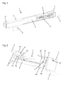
- einen Antrieb mit teilweise geschnittenem Gehäuse im Bereich des Elektromotors und des Platinenhalters im Schrägbild;
- Fig. 2
- eine weitere Ansicht im Schrägbild auf den Bereich des Elektromotors und des Platinenhalters mit angeordneter Endkappe, wobei das Gehäuse nicht gezeigt ist;
- Fig. 3
- den Platinenhalter als Einzelteil im Schrägbild;
- Fig. 4
- einen Ausschnitt eines Längsschnitts durch den Antrieb im Bereich des Platinenhalters.
- In
Fig. 1 ist ein Antrieb 1 zur Verriegelung eines Flügels eines hier nicht weiter dargestellten Fensters gezeigt, der in an sich bekannter Weise in ein Verrieglungsgestänge eingreift, das üblicherweise in einer Nut des Flügels angeordnet ist. - Der Antrieb 1 weist ein Gehäuse 2 auf, in dem ein mittels eines Elektromotors 3 angetriebenes Getriebe angeordnet ist, das beispielsweise als ein Spindel- oder Zahnstangengetriebe ausgebildet ist, wodurch ein Eingreifelement 4, das mit besagtem Verriegelungsgestänge zusammenwirkt, längs des Gehäuses 2 verlagerbar ist. Das Gehäuse 2 kann vorteilhaft als Aluminium-Vierkantrohr ausgebildet sein.
- Der Antrieb 1 weist weiterhin eine elektronische Schaltungsanordnung auf, die sich auf einer Platine 5 befindet, an welcher auch der elektrische Anschluss des Antriebs 1 erfolgt. Die Platine 5 ist vorteilhaft einfach und zuverlässig auf einem Platinenhalter 6 angeordnet, welcher die Platine 5 auch gegenüber dem Gehäuse 2 beabstandet und isoliert. Anschließend an den Platinenhalter 6 ist eine Endkappe 7 vorgesehen, wie es in
Fig. 2 gezeigt ist. Eine Anschlussleitung 8 wird im Bereich der Endkappe 7 von unten in das Gehäuse 2 geführt. Das Gehäuse 2 ist andernends mit einer Endkappe 9 verschließbar. - In der
Fig. 3 ist der Platinenhalter 6 als Einzelteil ohne eingesetzte Platine 5 gezeigt. Einerends weist der Platinenhalter 6 stirnseitig einen im Wesentlichen den inneren Abmessungen des Gehäuses 2 angepassten Halterahmen 10 auf, welcher hier mit Zungen 11 versehen ist, die den Elektromotor 3 umgreifen. Der Halterahmen 10 führt den Platinenhalter 6 im Gehäuse 2. Innerhalb einer Aussparung 12 des Halterahmens 10 ist eine optionale Abdeckung 13 angeordnet, welche eine in Richtung auf die Platine 5 zugewandte Welle des Elektromotors 3 abdeckt, wie es inFig. 2 gezeigt ist. - Vorteilhaft besteht durch die Anlage des Elektromotors 3 am Halterahmen 10 eine definierte Lage des Elektromotors 3 zur Platine 5, so dass beispielsweise ein auf der Welle des Elektromotors 3 angebrachter Magnet 14 direkt mit einem Sensor der auf der Platine 5 angeordneten Schaltungsanordnung einen Inkrementalgeber bilden kann, wodurch bevorzugt die Position des Eingreifelements 4 und somit die Verriegelungsstellung des Flügels des Fensters erfassbar ist. Die Abdeckung 13 schützt die Anschlussdrähte 15 des Elektromotors 3, welche durch die Aussparung 12 des Halterahmens 10 geführt sind, gegen Beschädigung, da eine Berührung der Anschlussdrähte 15 mit dem sich drehenden Magneten 14 verhindert wird. In alternativer Ausgestaltung können die Anschlussdrähte 15 auch außerhalb der Aussparung 12 um den Halterahmen 10 geführt sein.
- Der Platinenhalter 6 weist auf seiner der Endkappe 7 zugewandten Seite einen Befestigungsrahmen 16 auf, mit einer Aussparung 17 zum Durchgriff der Anschlussleitung 8, welche beispielsweise mittels Steckverbinder mit der Platine 5 verbindbar ist. Weiterhin ist am oberen horizontalen Steg des Befestigungsrahmens 16 eine Aufnahme 18 zur Befestigung der Endkappe 7 mittels einer Schaube 19 vorgesehen, wie es in
Fig. 4 gezeigt ist. Vor dem Befestigungsrahmen 16 ist am Platinenhalter 6 noch ein Bock 20 vorgesehen, an den ein Steg 21 angeschraubt werden kann, welche gemeinsam eine Zugentlastung für die Anschlussleitung 8 bilden. - Seitlich am Platinenhalter 6 sind Federelemente 22, welche den Platinenhalter 6 in dem Gehäuse 2 seitlich abstützen, durch die Anordnung von Schlitzen 23 realisiert. Nach außen hin ist an jedem Federelement 22 ein Gleitsteg 24 angeordnet, welcher ein Einschieben des Platinenhalters 6 in das Gehäuse 2 bei der Montage des Antriebs 1 erleichtert. Weiterhin sind am Platinenhalter 6 noch weitere Erhebungen und Aussparungen vorgesehen, welche zur Positionierung und Befestigung der Platine 5 auf dem Platinenhalter 6 vorgesehen sind. Die Platine 5 wird auf dem Platinenhalter 6 beispielsweise mittels Schrauben, Nieten oder Rastverbindungen angeordnet.
- An der Unterseite des Platinenhalters 6 ist besonders vorteilhaft ein Zapfen 25 vorgesehen, der mit einer Ausnehmung 26 im Gehäuse 2 zur einfachen und schnellen Montage des Antriebs 1 zusammenwirkt.
- Zur Montage des Antriebs 1 kann die Einheit aus Getriebe, Elektromotor 3 und aus Platinenhalter 6 mit Platine 5 nach Anschluss des Elektromotors 3 gemeinsam in das Gehäuse 2 eingeschoben werden, bis der auf der Unterseite des Platinenhalters 6 angeordnete Zapfen 25 in die Ausnehmung 26 im Gehäuse 2 eingreift. Das Getriebe und der Elektromotor 3 können beispielsweise durch Verschrauben im Bereich des Getriebes bzw. des Eingreifelements 4 im Gehäuse 2 festgelegt werden.
- In einer weiteren Alternative kann zunächst der mit dem Getriebe versehene Elektromotor 3 in das Gehäuse 2 eingeschoben werden und ebenfalls beispielsweise durch Verschrauben im Bereich des Getriebes bzw. des Eingreifelements 4 festgelegt werden. Der Platinenhalter 6 mit angeordneter Platine 5 kann nachfolgend in das Gehäuse 2 eingeschoben werden, wobei der Anschluss des Elektromotors 3 durch Kontaktieren eines elektrischen Steckverbinders auf der Platine 5 erfolgt. Sodann kann der Platinenhalter 6 mit seinem Halterahmen 10 vollständig an den Elektromotor 3 herangeführt werden. Zur Herstellung der elektrischen Verbindung können am Elektromotor 3 alternativ auch Kontaktstifte angeordnet sein, welche durch Heranschieben des Platinenhalters 6 in zugeordnete Buchsen auf der Platine 5 eingreifen.
- Der Antrieb 1 kann wahlweise gleich mit der Anschlussleitung 8 versehen werden, oder diese kann nachträglich bei der Montage des Antriebs 1 am Flügel des Fensters angebracht werden.
- Der durch den Eingriff des Zapfens 25 in die Ausnehmung 26 im Gehäuse 2 in Richtung der Längserstreckung des Gehäuses 2 positionierte Platinenhalter 6 wird vorteilhaft durch die Anordnung der Endkappe 7 an dem Platinenhalter 6 in dieser Position gehalten und gesichert, wobei sich die Endkappe 7 gegenüberliegend des Zapfens 25 am Gehäuse 2 abstützt.
- Die Endkappe 7 wird an dem Platinenhalter 6 festgelegt, indem die in einer Schraubenhülse 27 der Endkappe 7 aufgenommene Schraube 19 an der Aufnahme 18 am Befestigungsrahmen 16 des Platinenhalters 6 festgelegt wird. Durch diese Verbindung mit dem Platinenhalter 6 ist die Endkappe 7 ebenfalls in Richtung der Längserstreckung des Gehäuses 2 gesichert.
- Somit wird durch einfaches Einsetzen des Platinenhalters 6 und dem Verschließen des Antriebs 1 mit der Endkappe 7 mit nur einer Schraube 19 mit einfachen Mitteln ein sichere und schnelle Montage von Platinenhalter 6 und Endkappe 7 erzielt.
-
1 Antrieb 2 Gehäuse 3 Elektromotor 4 Eingreifelement 5 Platine 6 Platinenhalter 7 Endkappe 8 Anschlussleitung 9 Endkappe 10 Halterahmen 11 Zunge 12 Aussparung 13 Abdeckung 14 Magnet 15 Anschlussdraht 16 Befestigungsrahmen 17 Aussparung 18 Aufnahme 19 Schaube 20 Bock 21 Steg 22 Federelement 23 Schlitz 24 Gleitsteg 25 Zapfen 26 Ausnehmung 27 Schraubenhülse
Claims (10)
- Antrieb (1) für ein Fenster oder dergleichen, mit einem Gehäuse (2) und mit einem in dem Gehäuse (2) angeordneten Elektromotor (3) sowie mit einer zugeordneten Platine (5) mit einer elektronischen Schaltungsanordnung,
dadurch gekennzeichnet,
dass die Platine (5) in einem Platinenhalter (6) angeordnet ist, wobei der Platinenhalter (6) mit einem Halterahmen (10) im Gehäuse (2) geführt ist und mit einem Zapfen (25) in eine Ausnehmung (26) im Gehäuse (2) eingreift, wobei eine am Platinenhalter (6) festgelegte Endkappe (7) den Platinenhalter (6) mit dem Zapfen (25) im Eingriff mit der Ausnehmung (26) hält. - Antrieb nach Anspruch 1,
dadurch gekennzeichnet, dass der Halterahmen (10) eine Aussparung (12) zum Durchgriff eines auf einer Welle des Elektromotors (3) angebrachten Magneten (14) aufweist. - Antrieb nach Anspruch 2,
dadurch gekennzeichnet, dass der auf der Welle des Elektromotors (3) angebrachte Magnet (14) mit einem Sensor der auf der Platine (5) angeordneten Schaltungsanordnung einen Inkrementalgeber bildet. - Antrieb nach Anspruch 2,
dadurch gekennzeichnet, dass am Halterahmen (10) eine Abdeckung (13) vorgesehen ist, welche die Welle des Elektromotors (3) abdeckt. - Antrieb nach Anspruch 1,
dadurch gekennzeichnet, dass am Platinenhalter (6) ein Befestigungsrahmen (16) mit einer Aufnahme (18) zum Festlegen der Endkappe (7) am Platinenhalter (6) angeordnet ist. - Antrieb nach Anspruch 1,
dadurch gekennzeichnet, dass am Platinenhalter (6) ein Bock (20) angeordnet ist, welcher mit einem Steg (21) eine Zugentlastung für eine Anschlussleitung (8) bildet. - Antrieb nach Anspruch 5,
dadurch gekennzeichnet, dass der Befestigungsrahmen (16) eine Aussparung (17) zur Durchführung der Anschlussleitung (8) aufweist. - Antrieb nach Anspruch 1,
dadurch gekennzeichnet, dass am Platinenhalter (6) ein oder mehrere Federelemente (22) angeordnet sind, welche den Platinenhalter (6) im Gehäuse (2) elastisch abstützen. - Antrieb nach Anspruch 8,
dadurch gekennzeichnet, dass die Federelemente (22) durch Schlitze (23) im Platinenhalter (6) gebildet sind. - Verfahren zur Montage eines Antriebs nach Anspruch 1,
gekennzeichnet durch,- Anordnen des mit einem Getriebe versehenen Elektromotors (3) im Gehäuse (2);- gleichzeitiges oder anschließendes Einschieben des Platinenhalters (6) mit der Platine (5) mit Kontaktierung des Elektromotors (4) an der Platine (5);- Einsetzen des Zapfens (25) des Platinhalters (6) in die Aussparung (26) im Gehäuse (2) des Antriebs (1);- Festlegen des Platinenhalters (6) und der Endkappe (7) im Gehäuse (2) des Antriebs (1) durch Einsetzen der Endkappe (7) in das Gehäuse (2) und Festlegen der Endkappe (7) am Platinenhalter (6), wobei die Endkappe (7) den Platinenhalter (6) mit dem Zapfen (25) in der Ausnehmung (26) des Gehäuses (2) sichert.
Applications Claiming Priority (1)
| Application Number | Priority Date | Filing Date | Title |
|---|---|---|---|
| DE102012203738A DE102012203738B3 (de) | 2012-03-09 | 2012-03-09 | Antrieb für ein Fenster oder dergleichen sowie ein Verfahren zur Montage des Antriebs |
Publications (2)
| Publication Number | Publication Date |
|---|---|
| EP2637287A2 true EP2637287A2 (de) | 2013-09-11 |
| EP2637287A3 EP2637287A3 (de) | 2017-11-15 |
Family
ID=47503368
Family Applications (1)
| Application Number | Title | Priority Date | Filing Date |
|---|---|---|---|
| EP13158278.5A Withdrawn EP2637287A3 (de) | 2012-03-09 | 2013-03-08 | Antrieb für ein Fenster oder dergleichen sowie ein Verfahren zur Montage des Antriebs |
Country Status (2)
| Country | Link |
|---|---|
| EP (1) | EP2637287A3 (de) |
| DE (1) | DE102012203738B3 (de) |
Cited By (1)
| Publication number | Priority date | Publication date | Assignee | Title |
|---|---|---|---|---|
| CN105019732A (zh) * | 2015-07-21 | 2015-11-04 | 纽森电气制造(杭州)有限公司 | 一种智能电子锁 |
Families Citing this family (1)
| Publication number | Priority date | Publication date | Assignee | Title |
|---|---|---|---|---|
| FR3052933B1 (fr) * | 2016-06-15 | 2022-10-14 | Delta Dore | Moteur tubulaire pour un systeme d'obturation |
Citations (3)
| Publication number | Priority date | Publication date | Assignee | Title |
|---|---|---|---|---|
| DE19514229A1 (de) | 1995-04-15 | 1996-10-17 | Geze Gmbh & Co | Lastabschaltvorrichtung |
| DE19617083A1 (de) | 1996-04-29 | 1997-10-30 | Geze Gmbh & Co | Antriebsvorrichtung für den Flügel eines Fensters, einer Tür oder dergleichen |
| DE202009000361U1 (de) | 2009-01-09 | 2009-03-26 | SCHÜCO International KG | Fenster- oder Türelement |
Family Cites Families (2)
| Publication number | Priority date | Publication date | Assignee | Title |
|---|---|---|---|---|
| SE529217C2 (sv) * | 2005-05-20 | 2007-06-05 | Atlas Copco Tools Ab | Momentberoende utlösningskoppling för en skruvdragare |
| DE102010002817C5 (de) * | 2010-03-12 | 2016-06-09 | Geze Gmbh | Antrieb eines Fensters, einer Klappe oder dergleichen |
-
2012
- 2012-03-09 DE DE102012203738A patent/DE102012203738B3/de active Active
-
2013
- 2013-03-08 EP EP13158278.5A patent/EP2637287A3/de not_active Withdrawn
Patent Citations (3)
| Publication number | Priority date | Publication date | Assignee | Title |
|---|---|---|---|---|
| DE19514229A1 (de) | 1995-04-15 | 1996-10-17 | Geze Gmbh & Co | Lastabschaltvorrichtung |
| DE19617083A1 (de) | 1996-04-29 | 1997-10-30 | Geze Gmbh & Co | Antriebsvorrichtung für den Flügel eines Fensters, einer Tür oder dergleichen |
| DE202009000361U1 (de) | 2009-01-09 | 2009-03-26 | SCHÜCO International KG | Fenster- oder Türelement |
Cited By (1)
| Publication number | Priority date | Publication date | Assignee | Title |
|---|---|---|---|---|
| CN105019732A (zh) * | 2015-07-21 | 2015-11-04 | 纽森电气制造(杭州)有限公司 | 一种智能电子锁 |
Also Published As
| Publication number | Publication date |
|---|---|
| DE102012203738B3 (de) | 2013-01-31 |
| EP2637287A3 (de) | 2017-11-15 |
Similar Documents
| Publication | Publication Date | Title |
|---|---|---|
| EP1173918B1 (de) | Elektromotor, insbesondere zum heben und senken von scheiben bei kraftfahrzeugen | |
| EP0482040B1 (de) | Elektromotorischer fensterheber | |
| EP2542746B1 (de) | Fensterheberantrieb | |
| DE10318062A1 (de) | Getriebe-Antriebseinheit mit Elektronik-Schnittstelle | |
| DE202009008646U1 (de) | Elektromotorischer Verstellantrieb für ein Kraftfahrzeug | |
| EP2787156A2 (de) | Türgestänge | |
| DE19916958A1 (de) | Elektromotorischer Antrieb, insbesondere Fensterheberantrieb für ein Kraftfahrzeug | |
| DE102007043372A1 (de) | Antriebsanordnung für ein verstellbares Funktionselement in einem Kraftfahrzeug | |
| EP1971743B1 (de) | Antriebsvorrichtung | |
| EP2634344B1 (de) | Antrieb für einen Flügel eines Fensters oder dergleichen sowie ein Verfahren zur Montage einer Endkappe des Antriebs | |
| EP1514001B1 (de) | Antriebsvorrichtung | |
| DE102012203738B3 (de) | Antrieb für ein Fenster oder dergleichen sowie ein Verfahren zur Montage des Antriebs | |
| DE102012104259B4 (de) | Gleichstrommotor zum Antrieb von Aggregaten eines Kraftfahrzeugs | |
| DE102005050750B4 (de) | Befestigungsvorrichtung für Antriebseinheit mit Kunststoffgehäuse | |
| WO2006117265A1 (de) | Verbindungsvorrichtung | |
| DE102009001714A1 (de) | Elektrischer Antriebsmotor, insbesondere für ein Aggregat in einem Kraftfahrzeug | |
| DE10108414B4 (de) | Elektromotorischer Fensterheberantrieb | |
| EP0964137A2 (de) | Drosselklappenstutzen | |
| EP2637286B1 (de) | Antrieb für ein Fenster oder dergleichen sowie ein Verfahren zur Montage des Antriebs | |
| DE102008053036A1 (de) | Antriebsbaugruppe für die motorische Verstellung eines Verstellelements in einem Kraftfahrzeug | |
| DE102013202857A1 (de) | Bürstenträger für einen Elektromotor und Getriebe-Antriebseinheit mit einem Bürstenträger | |
| DE102007030088B4 (de) | Antrieb zum Betätigen eines beweglichen Flügels, insbesondere einer Tür oder eines Fensters | |
| EP3479461A1 (de) | Kombination aus motorgehäuse und steckeranschluss sowie dafür vorgesehenes motorgehäuse | |
| WO2010115534A1 (de) | Scheibe eines kraftwagens | |
| DE20122561U1 (de) | Elektromotorischer Fensterheberantrieb |
Legal Events
| Date | Code | Title | Description |
|---|---|---|---|
| PUAI | Public reference made under article 153(3) epc to a published international application that has entered the european phase |
Free format text: ORIGINAL CODE: 0009012 |
|
| AK | Designated contracting states |
Kind code of ref document: A2 Designated state(s): AL AT BE BG CH CY CZ DE DK EE ES FI FR GB GR HR HU IE IS IT LI LT LU LV MC MK MT NL NO PL PT RO RS SE SI SK SM TR |
|
| AX | Request for extension of the european patent |
Extension state: BA ME |
|
| PUAL | Search report despatched |
Free format text: ORIGINAL CODE: 0009013 |
|
| AK | Designated contracting states |
Kind code of ref document: A3 Designated state(s): AL AT BE BG CH CY CZ DE DK EE ES FI FR GB GR HR HU IE IS IT LI LT LU LV MC MK MT NL NO PL PT RO RS SE SI SK SM TR |
|
| AX | Request for extension of the european patent |
Extension state: BA ME |
|
| RIC1 | Information provided on ipc code assigned before grant |
Ipc: H02K 7/14 20060101ALI20171010BHEP Ipc: H02K 11/00 20160101AFI20171010BHEP Ipc: H02K 5/22 20060101ALI20171010BHEP Ipc: E05F 15/14 00000000ALI20171010BHEP Ipc: E05B 47/00 20060101ALI20171010BHEP |
|
| 17P | Request for examination filed |
Effective date: 20171123 |
|
| RBV | Designated contracting states (corrected) |
Designated state(s): AL AT BE BG CH CY CZ DE DK EE ES FI FR GB GR HR HU IE IS IT LI LT LU LV MC MK MT NL NO PL PT RO RS SE SI SK SM TR |
|
| RIC1 | Information provided on ipc code assigned before grant |
Ipc: H02K 5/22 20060101ALI20190311BHEP Ipc: E05F 15/632 20150101ALI20190311BHEP Ipc: E05F 15/611 20150101AFI20190311BHEP Ipc: H02K 11/33 20160101ALI20190311BHEP Ipc: E05B 47/00 20060101ALI20190311BHEP Ipc: H02K 7/14 20060101ALI20190311BHEP |
|
| GRAP | Despatch of communication of intention to grant a patent |
Free format text: ORIGINAL CODE: EPIDOSNIGR1 |
|
| INTG | Intention to grant announced |
Effective date: 20190425 |
|
| STAA | Information on the status of an ep patent application or granted ep patent |
Free format text: STATUS: THE APPLICATION HAS BEEN WITHDRAWN |
|
| 18W | Application withdrawn |
Effective date: 20190606 |