EP2636929A2 - Locking unit - Google Patents
Locking unit Download PDFInfo
- Publication number
- EP2636929A2 EP2636929A2 EP13157427.9A EP13157427A EP2636929A2 EP 2636929 A2 EP2636929 A2 EP 2636929A2 EP 13157427 A EP13157427 A EP 13157427A EP 2636929 A2 EP2636929 A2 EP 2636929A2
- Authority
- EP
- European Patent Office
- Prior art keywords
- pawl
- locking unit
- piston
- spring
- unit according
- Prior art date
- Legal status (The legal status is an assumption and is not a legal conclusion. Google has not performed a legal analysis and makes no representation as to the accuracy of the status listed.)
- Granted
Links
Images


Classifications
-
- B—PERFORMING OPERATIONS; TRANSPORTING
- B60—VEHICLES IN GENERAL
- B60T—VEHICLE BRAKE CONTROL SYSTEMS OR PARTS THEREOF; BRAKE CONTROL SYSTEMS OR PARTS THEREOF, IN GENERAL; ARRANGEMENT OF BRAKING ELEMENTS ON VEHICLES IN GENERAL; PORTABLE DEVICES FOR PREVENTING UNWANTED MOVEMENT OF VEHICLES; VEHICLE MODIFICATIONS TO FACILITATE COOLING OF BRAKES
- B60T1/00—Arrangements of braking elements, i.e. of those parts where braking effect occurs specially for vehicles
- B60T1/005—Arrangements of braking elements, i.e. of those parts where braking effect occurs specially for vehicles by locking of wheel or transmission rotation
-
- F—MECHANICAL ENGINEERING; LIGHTING; HEATING; WEAPONS; BLASTING
- F16—ENGINEERING ELEMENTS AND UNITS; GENERAL MEASURES FOR PRODUCING AND MAINTAINING EFFECTIVE FUNCTIONING OF MACHINES OR INSTALLATIONS; THERMAL INSULATION IN GENERAL
- F16H—GEARING
- F16H63/00—Control outputs from the control unit to change-speed- or reversing-gearings for conveying rotary motion or to other devices than the final output mechanism
- F16H63/02—Final output mechanisms therefor; Actuating means for the final output mechanisms
- F16H63/30—Constructional features of the final output mechanisms
- F16H63/34—Locking or disabling mechanisms
-
- F—MECHANICAL ENGINEERING; LIGHTING; HEATING; WEAPONS; BLASTING
- F15—FLUID-PRESSURE ACTUATORS; HYDRAULICS OR PNEUMATICS IN GENERAL
- F15B—SYSTEMS ACTING BY MEANS OF FLUIDS IN GENERAL; FLUID-PRESSURE ACTUATORS, e.g. SERVOMOTORS; DETAILS OF FLUID-PRESSURE SYSTEMS, NOT OTHERWISE PROVIDED FOR
- F15B15/00—Fluid-actuated devices for displacing a member from one position to another; Gearing associated therewith
- F15B15/20—Other details, e.g. assembly with regulating devices
- F15B15/26—Locking mechanisms
- F15B15/261—Locking mechanisms using positive interengagement, e.g. balls and grooves, for locking in the end positions
-
- F—MECHANICAL ENGINEERING; LIGHTING; HEATING; WEAPONS; BLASTING
- F16—ENGINEERING ELEMENTS AND UNITS; GENERAL MEASURES FOR PRODUCING AND MAINTAINING EFFECTIVE FUNCTIONING OF MACHINES OR INSTALLATIONS; THERMAL INSULATION IN GENERAL
- F16H—GEARING
- F16H63/00—Control outputs from the control unit to change-speed- or reversing-gearings for conveying rotary motion or to other devices than the final output mechanism
- F16H63/02—Final output mechanisms therefor; Actuating means for the final output mechanisms
- F16H63/30—Constructional features of the final output mechanisms
- F16H63/34—Locking or disabling mechanisms
- F16H63/3416—Parking lock mechanisms or brakes in the transmission
- F16H63/3425—Parking lock mechanisms or brakes in the transmission characterised by pawls or wheels
- F16H63/3433—Details of latch mechanisms, e.g. for keeping pawls out of engagement
-
- F—MECHANICAL ENGINEERING; LIGHTING; HEATING; WEAPONS; BLASTING
- F16—ENGINEERING ELEMENTS AND UNITS; GENERAL MEASURES FOR PRODUCING AND MAINTAINING EFFECTIVE FUNCTIONING OF MACHINES OR INSTALLATIONS; THERMAL INSULATION IN GENERAL
- F16H—GEARING
- F16H63/00—Control outputs from the control unit to change-speed- or reversing-gearings for conveying rotary motion or to other devices than the final output mechanism
- F16H63/02—Final output mechanisms therefor; Actuating means for the final output mechanisms
- F16H63/30—Constructional features of the final output mechanisms
- F16H63/34—Locking or disabling mechanisms
- F16H63/3416—Parking lock mechanisms or brakes in the transmission
- F16H63/3458—Parking lock mechanisms or brakes in the transmission with electric actuating means, e.g. shift by wire
- F16H63/3475—Parking lock mechanisms or brakes in the transmission with electric actuating means, e.g. shift by wire using solenoids
-
- F—MECHANICAL ENGINEERING; LIGHTING; HEATING; WEAPONS; BLASTING
- F16—ENGINEERING ELEMENTS AND UNITS; GENERAL MEASURES FOR PRODUCING AND MAINTAINING EFFECTIVE FUNCTIONING OF MACHINES OR INSTALLATIONS; THERMAL INSULATION IN GENERAL
- F16H—GEARING
- F16H63/00—Control outputs from the control unit to change-speed- or reversing-gearings for conveying rotary motion or to other devices than the final output mechanism
- F16H63/02—Final output mechanisms therefor; Actuating means for the final output mechanisms
- F16H63/30—Constructional features of the final output mechanisms
- F16H63/34—Locking or disabling mechanisms
- F16H63/3416—Parking lock mechanisms or brakes in the transmission
- F16H63/3483—Parking lock mechanisms or brakes in the transmission with hydraulic actuating means
Definitions
- the invention relates to a locking unit for locking the movement of a movable piston by a drive, wherein the locking unit comprises an electromagnet and a latching assembly comprising a spring portion and a pawl portion, wherein the elastic spring portion of the detent assembly against the armature or the anchor rod of the electromagnet or against a held by the anchor or the anchor rod pin such that in a locked position of the pawl portion blocks the movement of the piston, wherein in an unlocked position, the movement of the piston is released.
- the aforementioned locking units find particular use in the parking brake of automatic transmissions.
- a vehicle with manual transmission can be secured by inserting a gear against unintentional rolling away at standstill with the engine off.
- automatic transmissions however, this is not possible because when the engine is off no adhesion to the drive wheels.
- Automatic transmissions therefore have a mechanical locking of the transmission output shaft which is to be activated in the parking position, that is to be adjusted, thus preventing the vehicle from rolling away.
- the locking unit acts together with the hydraulic circuit of the automatic transmission.
- the piston is unlocked.
- the piston rod of the piston acts with a blocking element in a suitable manner on the drive train. In the driving position, so with the parking brake off, the moving, in particular pressurized piston is locked.
- a generic locking unit results for example from the European patent 1 408 260 ,
- the latching assembly which is known in the art as a one-piece or one-piece component, fulfills at least two tasks.
- the latch portion of the latch assembly cooperates with the piston to block movement of the piston in the latching position.
- the latch region of the latching assembly is characterized in that it is the local area on the latching assembly, which is assigned to the piston or which cooperates with the piston.
- the pawl region encompasses not only a hook, pawl, projection or shoulder, which interacts in a suitable manner with the piston, but also other areas. Usually, just the pawl area in the direction of movement of the piston is mechanically stressed accordingly train or impact.
- a spring region is also provided on the catch assembly.
- the spring region has a corresponding elastic configuration in order to achieve that the latching assembly is employed radially or at an angle, relative to the direction of movement of the piston, against the armature or the anchor rod of the electromagnet or against a bolt held by the armature or the anchor rod or a corresponding pretension having.
- a cam or other guide element is provided on the latching assembly, which in a suitable manner cooperates with the armature, the anchor rod or the pin and be deflected by the movement of the armature (when energized by the electromagnet) in angled or perpendicular or radial direction with respect to the direction of movement of the piston.
- the arrangement is chosen so that blocked in a locking position of the pawl region, the movement of the piston. Due to the elastic configuration of the spring region, the latching assembly is at least partially moved or pivoted so that the pawl region with the piston or the piston head, which has a corresponding undercut, notch or the like, can cooperate and so the movement of the piston is blocked.
- the locking position corresponds to the attracted electromagnet, that is, the current-loaded electromagnet, whereby the bolt, which is arranged on the anchor rod or the armature, does not cooperate with the provided on the latch assembly cams in the fallen (solenoid is not energized)
- Unlocking position the latch assembly is outwardly so that the latch area can not interact with the piston head.
- the invention is based on a locking unit, as described above, and proposes that the pawl region has an acting at least in the direction of movement of the piston reinforcement.
- the reinforcement is formed by an increase in the specific strength of the material of the pawl region caused by heat treatment.
- it is known to anneal a metal by heat treatment so as to have a higher specific strength thereafter, as before.
- the heat treatment is preferably limited only to the pawl area in order to provide this area where the higher strength is important.
- it is surprisingly harmless for the invention when the entire catch assembly, including the spring range, undergoes the same or a similar heat treatment, which makes the corresponding step can be carried out considerably easier.
- the increase in strength associated with the heat treatment which also leads to a more brittle material, is harmless in the spring area.
- the heat treatment for the spring area is just harmful and there then a deterioration of the properties results (for example, faster breakage of the detent assembly in the spring area due to the brittle material) which in the present case but just is not the case.
- a relative increase in strength of at least 4%, preferably of at least 5% results from the heat treatment, which preferably follows a deformation step in the production of the catch assembly.
- the material of the pawl portion (or detent assembly as a whole) has a hardness of 324 HV (Vickers hardness) which increased to about 345 HV after the heat treatment.
- This relatively small increase in hardness leads to an improvement in the tensile strength, especially in the pawl area. This results in a significant, approximately at least four times higher lifetime of the locking unit according to the invention leads!
- the entire detent assembly but at least the pawl region, is formed from an at least cold, permanently deformable spring steel.
- the locking unit according to the invention is produced in very high numbers.
- a locking unit usually has more than just one latching assembly, often, for example, three latching assemblies are installed in a locking unit. Due to the mass production of course, a cost-effective production of importance, by the most efficient use of shaping and / or bending and / or punching tools is achieved, which preferably performs all necessary work on the latching assembly, in particular in the latch area and so on, in a reliabilitys strengtheningmaschinen deformation step.
- the material of the latching assembly but at least the pawl region, to be selected so that on the one hand a permanent deformability of the material is given, on the other hand, but the resilient property of the latching assembly, which is provided in particular by the spring area also provided is.
- the invention here, for example (but not exclusively) proposes chromium-nickel steels.
- the material for example a steel
- the material is made available, for example, as strip material and punched out of the material in a continuous process by shaping.
- the production of the preferably integrally formed latching assembly or at least the pawl part in a multi-part embodiment of the latching assembly takes place in several steps.
- the deformation step which combines both punching, so material removing steps such as forming, bending or deep drawing processing steps, for example, followed by a heat treatment step, in which then brought into shape and contour brought element by the heat treatment strength increase.
- the gain of the pawl region be increased by increasing the Material thickness of the pawl region forming material is achieved.
- so-called step plates are known, which have a different material thickness and in which the mechanically more highly stressed latch region has a greater material thickness and therefore greater stability.
- the usual way existing material thickness of the latch assembly in the latch range of 0.5 mm to 0.8 mm or 1 mm increase.
- the pawl element has a holding surface which cooperates with the piston in the locking position and the reinforcement on the pawl region is located on the side of the pawl element facing away from the holding surface.
- the latch region is at least formed by a latch element and a latch carrier, wherein the latch element projects at right angles or at an angle, in particular in the direction of the piston towards the latch carrier.
- the pawl element has the task of actually holding together cooperate with the piston, for which purpose a holding surface is provided on the pawl element.
- the amplification is skillfully arranged on the side of the latch element facing away from the holding surface.
- the reinforcement is designed as a refolding, in particular as an end-side refolding of the material of the pawl carrier.
- a refolding can be realized in a simple manner in the shaping deformation step of the catch assembly or of the pawl carrier and ultimately leads, similar to the proposal of the use of a stepped plate, to a corresponding material doubling and thus to a reinforcement.
- the latching support or the latching assembly is formed in one piece by the refolding and undergoes reinforcement.
- the reinforcement is designed as a separately used support, which is arranged for example in an adhesive, soldering or welding step at the desired location on the latch carrier or the latch assembly.
- the latching assembly is configured in one piece or formed in one piece.
- the latching assembly consists of a, preferably homogeneous, material without the invention being limited thereto. It is also possible to realize a one-piece or one-piece design of the latching assembly of a heterogeneous material composition, in which case skilfully fashioned spring region and pawl region are optimized for their respective properties, in particular in the pawl region a reinforcement is provided. In this case, the gain can be realized for example in a special choice of material of the pawl area or material compensation or actually by a mechanical upgrade.
- homogeneous material also includes materials having the same properties, but it is also to speak of a heterogeneous material, although this does not undergo any changes in its chemical properties, but nevertheless different properties, for example due to a Heat treatment partially. Also similar proposals are included in the inventive concept.
- the invention also includes a proposal in which the latching assembly consists of at least two parts, that is, a two-part design of the latching assembly is selected.
- the spring portion is realized on a spring member and the pawl portion on a pawl part, wherein spring member or pawl part are made as independent, independent components, but which are assembled later in the catch assembly and cooperate.
- Such a dissected structure of the detent assembly has the significant advantage that each of the detent assembly with respect to their various properties (springing and holding) is designed optimized and the appropriate measures can be selected independently for each optimization.
- the two components are suitably connected together, either mechanically caulked, glued, welded, soldered or held together by a third element.
- the spring part is formed from a good resilient material, for example a spring steel or a spring wire or the spring part is formed from a, at least cold permanently deformable spring steel.
- the spring part is optimized in this variant to the resilient, elastic property.
- the material of the pawl member has a higher tensile strength, as the material of the spring member, whereby the increased mechanical stress of the pawl part, especially in the pawl area, is taken into account.
- the pawl part or the latching assembly has a, in particular in the direction of movement of the piston, in particular acting as a reinforcement spring element.
- This acting in the direction of movement of the piston spring element has shock absorber properties. Therefore, it also acts as a reinforcement in the sense of the invention to compensate for the mechanical shock acting on the pawl portion in the locking position something and thus increase the life of the locking unit according to the invention accordingly. It is clear that the arrangement of this spring element can be realized both in the one-piece detent assembly, as well as in a multi-part detent assembly having a pawl part and a spring part.
- the spring element is realized in sections, for example, by a meander-shaped design of the latch member or the latch assembly, this spring element is preferably provided in the latch area or pawl part and so does not affect the resilient elastic task of the spring member having a different direction of action.
- the invention does not exclude a corresponding local superimposition of these two properties.
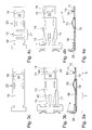
- a first variant of the locking unit 1 serves for locking the movement 3 of a piston 2 which can be moved by a drive.
- the movement 3 of the piston 2 is identified by the double arrow 3.
- the piston 2 is in one Housing 23 out and stored.
- a separate drive is provided or the piston 2 is part of a preferably hydraulically acting working cylinder (alternatively, of course, a pneumatic working cylinder is conceivable), which is in communication with the hydraulic circuit of an automatic transmission.
- the pressure chamber 25 is acted upon by hydraulic pressure of the system, whereby the movably mounted piston 2 is offset to the right, as in Fig. 1b is shown.
- the fork-like blocking element 26 is disengaged from corresponding transmission parts of the vehicle, which reaches an additional, in particular positive locking of the transmission output shaft when the engine is switched off (when the hydraulic pump or the parking position).
- the released position of the parking brake is to secure accordingly, so to lock, which takes place with the locking unit 1 according to the invention.
- the activated locking unit is in its locking position in Fig. 1b shown.
- the structure of the locking unit 1 is characterized in that the piston 2 is movably mounted at its left end, which has a hook-like piston head 5.
- the latch assembly 6 which is provided in the housing 23 substantially stationary (not axially, in the direction of movement 3 of the piston 2, as a whole movable), but for example pivotally mounted.
- the latching assembly 6 cooperates on the one hand with the piston head 5 and the piston 2 and on the other hand with the bolt 11 moved by the electromagnet 4. Due to the movement of the bolt 11, the latching assembly 6 comes into operative engagement with the piston 2.
- the electromagnet 4 joins the detent assembly 6 on the right, on the opposite side of the piston 2.
- the structure of the electromagnet 4 is as usual, the solenoid 4 has a coil 27 with a plurality of current-flowable windings.
- a magnetic field is generated which acts on the movable elements of the electromagnet 4, in particular on the armature 9.
- a magnetic field is generated by the current-applied coil 27, which tries to move the armature 9 to the right so that the air gap 28 is closed. This is done against the restoring force of a return spring 29.
- the return spring 29 is located on the left, outside of the electromagnet 4, which is limited by the yoke 30.
- the armature 9 is axially guided and movable in a corresponding bore of the yoke 30.
- the armature 9 carries concentrically mounted or arranged an anchor rod 10, which in turn is guided on the right side of the air gap 28, the yoke 30 side facing away in a bore of the core 31.
- the yoke 30 has a stepped bore, so as to serve not only the storage of the armature 9, but also the storage of the anchor rod 10.
- the anchor rod 10 transmits the movement of the armature 9 movably arranged in the interior of the electromagnet 4 to components outside the electromagnet 4, in particular to the left of the yoke 30, such as, for example, the bolt 11 arranged on the anchor rod 10.
- the arrangement is chosen so that between the latch assembly 6 and the electromagnet 4, the yoke 30 is disposed and the electromagnet 4 on the side facing away from the yoke 30 (relative to the coil axis of the coil 27), which in the application example parallel to the direction of movement. 3 is from that Kern 31 is completed.
- the invention is not limited to the specific embodiment of the electromagnet 4, but the locking unit according to the invention in the design of the electromagnet 4, in particular in their spatial arrangement, is very variable. It is quite possible in a variant according to the invention that the armature 9 is led out of the coil interior of the coil 27 and is dispensed with the use of a separate anchor rod 10 and the bolt 11 is directly supported by the armature 9.
- the invention also encompasses a variant in which the bolt 11 is integrally formed with the anchor rod 10 or the armature 9, that is, the bolt 11 forms only a functional portion of the armature 9 or the anchor rod 10 or the bolt 11 is discrete, realized own manufactured element, which is constructed in a corresponding assembly step on the armature 9 and the anchor rod 10.
- the latter is advantageous because the restoring spring 29 is supported, on the one hand, outside the electromagnet 4 on the side of the yoke 30 facing away from the electromagnet 4 and, on the other hand, on the abutment surface 32 of the bolt 11 facing the electromagnet 4.
- the assembly is carried out so that the finished assembly electromagnet 4, which has guided through the bore of the yoke 30 anchor rod 10 to which then the return spring 29 can be placed and then placed on the anchor rod 10 finally the bolt 11 and fixed in the axial direction , for example, is caulked.
- the locking unit 1 has a plurality of individual latching assemblies 6.
- three locking assemblies 6 are arranged in the circumferential direction around the anchor rod 10, wherein for a uniform load, preferably provided a concentric arrangement is.
- the individual locking assemblies are each arranged equidistant from each other and therefore ideally all burdened the same.
- the latching assembly 6 is fixed in the axial direction (which is parallel to the direction of movement 3 of the piston 2 and the direction of movement 33 of the armature 9), however, pivotally mounted on the carrier 22 or hinged and thus radially movable.
- the carrier 22 is in the embodiment shown here a part of the yoke 30.
- the catch assembly 6 extends in the axial direction and is significantly elongated. Based on the inner diameter of the housing 23, in which the latching assembly 6 is arranged, the length of the latching assembly 6 is greater than the inner diameter, preferably at least 1.5 or 2 inner diameters of the housing 23.
- Locking assembly 6 of the locking unit 1 according to the invention shown is formed by a spring portion 7 and a pawl region eighth
- the spring region 7 adjoins the bearing region 34.
- the latching assembly 6 is connected to the carrier 22.
- the latch portion is the opposite end of the bearing portion 34 of the latch assembly 6 .
- the latching assembly 6 is in several parts, in particular in two parts, formed.
- the spring portion 7 in an independent component, the spring member 19, realized.
- the pawl region 8 is likewise formed by an independent component, the pawl part 18.
- a spatial overlap of spring portion 7 and pawl portion 8 is possible because the individual components, the pawl member 18 and the spring member 19, in the axial direction in same areas.
- the functional area, spring area 7 or latch area 8, respectively is realized by separate components, which are optimally adapted to the respective task. In a one-piece configuration, however, these areas may also overlap at least partially.
- the task of the spring member 19 is to impress on the catch assembly 6 sufficient bias such that the catch assembly 6 would like to pivot in the direction of the Koblens 2 and the piston head 5. This is achieved by a corresponding elasticity of the spring region 7 or of the spring part 19.
- the spring member 19 is formed, for example, as a discrete spring, for example of a spring wire or as a resilient member made of a spring steel or the like.
- the bearing area 34 ultimately serves as a bearing or pivot point for the latching assembly 6.
- the latching assembly 6 is biased in the direction of the piston head 5 out. This adjustment movement, which is indicated by the spring region 7 or spring part 19 with the arrow 35, this is a pivoting movement about the bearing portion 34.
- the catch assembly is located 6 on the bolt 11.
- the latching assembly 6 has a cam 20 which slides along the lateral surface of the bolt 11 according to the axial position of the bolt 11. In areas of larger diameter, the bolt 11 causes an expression, ie a radially outwardly directed movement of the latch assembly 6, which provided on the latch assembly 6 latch portion 8 is radially removed from the piston head 5.
- radial refers to the axial direction, by the direction of movement 3 of the piston or the parallel direction of movement 33 of the armature 9 is predetermined.
- the effective diameter of the tapered pin 11, which is in operative contact with the cam 20, is dependent on the axial position of the anchor rod 10.
- the bolt 11 is fixedly connected to the anchor rod 10, in turn, the anchor rod 10 is fixedly connected to the armature 9.
- the axial position of the bolt 11 depends on the axial position of the armature 9 in the electromagnet 4 from which, when no current flows through the coil 27, as in Fig. 1a shown, the return spring 29, the arrangement of armature 9, anchor rod 10 and pin 11 pushes to the left and thus the latch assembly to the outside.
- the arrangement is chosen so that the latching assembly 6 with its bearing portion 34 on the carrier 22, which is part of the yoke 30, movable, in particular pivotable, at least flexibly or elastically bendable, whereby the pawl region 8 in a respect to the direction of movement of the Piston 2 right-angled, acute-angled or radial pivoting movement against the piston 2 and the piston head 5 can be adjusted.
- the piston 2 in particular the piston head 5 of the piston 2, has an undercut, a shoulder, collar, ring, Projection or retaining lug 36 which cooperates with the elements of the pawl region 8 at least non-positively or positively.
- the latch member 13 is formed for example by a hook, latch, projection, paragraph, catch or the like.
- the reinforcement 12 provided according to the invention is preferably located in the pawl region 8 Fig.
- the reinforcement 12 in particular in the two-part embodiment of the latch assembly 6 realized in which the pawl member 18 has a significantly higher tensile strength, such as the spring member 19, wherein the pawl member 18 has a significantly lower tendency to spring than the spring member 19.
- the operation of the locking unit 1 according to the invention is as follows.
- the parking lock is active, for example, when the vehicle is parked, the engine is off, the hydraulic circuit of the automatic transmission is not under pressure. Since no electrical load is active in this position or should be active in order to save energy, the windings of the coil 27 are not energized, therefore, no magnetic field at the electromagnet 4 is active. Thus, only the return spring 29 acts.
- the pin 11 is so offset to the left, whereby the bolt pushes the cams 20 of the latch assembly 6 radially outward and the unlocking defined by the fact that the pawl portion 8 is not engaged with the piston head 5.
- the piston 2 is displaced by residual pressure inside the housing to the left.
- the blocking element 26 is to be removed from the gear train. This is done by a corresponding pressurization of the pressure chamber 25, for example, with the system pressure of the hydraulic circuit of the automatic transmission, through which the piston 2 is pushed into the housing 23 and the piston rod 37, which carries the blocking element 26, dips into the housing 23. In this driving position, the position of the piston must now be secured to ensure that the blocking element 26 does not accidentally enter the gear train. This is done by the in Fig.
- Fig. 2a, 2b the same construction of the locking unit 1 according to the invention is shown, as in Fig. 1a, 1b , However, the configuration of the latching assembly 6 differs, which is why this feature is increasingly addressed here.
- Fig. 1a, 1b is the two-piece locking assembly 6 formed from a made of relatively stable or thick material pawl member 18 and a spring member 19 which can be realized for example as a spiral spring or spring wire.
- the cam 11 of the latching assembly 6 which is supported on the bolt 11 is in Fig. 1a, 1b formed by the stable latch member 18.
- the cam 20 is realized by the spring part 19 or is likewise formed by the pawl part 18.
- the latch assembly 6 is formed in two parts, wherein the latch portion 8, which is formed by the separate pawl member 18, a reinforcement 12, which consists for example in the appropriate choice of material and / or other constructive variants.
- the reinforcement 12 it is possible to effect the reinforcement 12 by a correspondingly harder, more resistant material of the latch member 18 in order to permanently resist the continuous impacts of the piston 2 on the latch member 13 and thus increase the life of the locking unit according to the invention.
- the pawl part 18 is designed as a forging or casting element, as a result of which a correspondingly greater material thickness can be realized. But it is also possible to produce this pawl part of a drawn or rolled material.
- the pawl part is formed from a band or flat material, which has also been preferably cold-formed in a forming step. Due to the functional decoupling of the spring region 7 and the pawl region 8 into two separate components, the respective components can be optimized for their specific function. Thus, then also formed from a tape or flat spring member 19 takes over the preload function, as well as in Fig. 1a, 1b an inwardly, in the direction of the piston head 5 resulting force or torque to impress on the catch assembly 6. On the spring part 19, the latching assembly 6 is then also articulated on the carrier 22 in the storage area 34, for which there is a separate retaining ring or caulking or the like.
- FIG. 3a, 3b, 3c or 4a, 4b, 4c two different variants of a two-part latch assembly 6 are shown.
- the foot region of the latching assembly 6 is shown, in which the latching assembly 6 is connected to the support 22 in the storage area 34.
- the foot region 38 is part of the spring part 19 of the two-part latch assembly 6.
- the foot region 38 is at right angles from the longitudinally extending latch assembly 6, the bend is arranged on the same side as the pawl member 13 on the latch assembly 6.
- Locking assembly 6 is made separately and suitably for Locking assembly 6 is connected, wherein, for example, a solder joint, a mechanical caulking or other sufficiently stable connection between the parts is provided.
- the pawl member 18 is slightly larger in its longitudinal extent, that is longer, as the spring member 19. It forms in the central region of the inwardly projecting cam 20, the cam 20 is therefore arranged on the same side as the angled foot portion 38 or Pawl element 13.
- the latch member 18 has at the end facing away from the foot portion 38 a punched-39, at the side facing away from the foot portion 38 side the pawl member 13 protrudes from the longitudinally extending pawl carrier 14.
- the pawl member 13 forms on the punching 39 side facing a holding surface 15 which cooperates with the retaining lug, detent, projection or other retaining element of the piston head 5 at least non-positively, if not positively.
- a reinforcement 12 which is formed both by a corresponding material or mechanical reinforcement.
- Fig. 3c shows the latch member 18 as a separate, single manufacturable component.
- the punching 39 has in this case laterally next to the bent pawl element 13 with recesses 40, which also serve to reinforce, that is, a notch effect between the bent pawl element 13 and the pawl carrier 14th prevents.
- Fig. 3c In comparison between Fig. 3c and Fig. 4c The difference between these two variants of the embodiment of a latching assembly 6 according to the invention is also shown.
- this spring element 21 can also be used as reinforcement 12 in the sense of the invention, since it has a shock-absorbing and therefore reinforcing property.
- the design of the spring element 21 is realized by a meander-shaped structure or punching 39 in the flat material of the pawl member 18.
- the material of the pawl member 18 is realized as a spring steel and the like.
- the spring member 19 is tapered trapezoidal in the central region 41 and has centrally a longitudinal punching 42. By this geometry, the resilient property is supported accordingly.
- the middle region 41 is located between the cam 20 and the foot region 38.
- Fig. 5a, 5b shows a substantially one-piece design of the latch assembly 6.
- the latch assembly 6 is divided into the spring portion 7 and the pawl portion 8, wherein the spring portion 7, in particular adjoins the foot portion 38 and a trapezoidal extending middle portion 41, similar to Fig. 3b or Fig. 4b , having.
- the punch 42 is provided in the same way.
- the spring region 7 extends between the cam 20 and the foot region 38.
- the pawl region 8 connects.
- the reinforcement 12 is in this case on the side facing away from the holding surface 15 of the pawl member 13.
- the reinforcement 12 is formed in the embodiment shown here by a refolding 16 of the material of the latch assembly 6.
- the material of the latching assembly 6, which is embodied here in one piece, is formed, for example, by a spring steel available as a flat or strip material in a thickness of 0.5 mm, 0.7 mm, 0.9 mm or 1 mm in thickness. From the comparable material, it is also possible to realize the spring part 19 or pawl part 18 in a two- or multi-part embodiment of the latching assembly 6. Skillfully, the material thickness of the pawl member is then increased to increase the strength of the pawl member to form the reinforcement 12.
- Fig. 6a, 6b shows a further variant of a one-piece latching assembly 6, which in the construction of the in Fig. 5a, 5b strongly resembles the example shown.
- the reinforcement 12 is formed by a support 17, which adjoins the side of the latch element 13 facing away from the holding surface 15.
- the support 17 is designed as a separate support element and inserted into the back of the pawl element 13.
- a stable attachment results, for example, by a caulking, so a mechanical composite or by gluing, welding or soldering.
Abstract
Description
Die Erfindung betrifft eine Verriegelungseinheit für das Verriegeln der Bewegung eines, von einem Antrieb bewegbaren Kolbens, wobei die Verriegelungseinheit einen Elektromagneten und eine Rastbaugruppe mit einem Federbereich und einem Klinkenbereich umfasst, wobei der elastische Federbereich die Rastbaugruppe gegen den Anker beziehungsweise die Ankerstange des Elektromagneten oder gegen einen vom Anker beziehungsweise der Ankerstange gehaltenen Bolzen derart anstellt, dass in einer Verriegelungsstellung der Klinkenbereich die Bewegung des Kolbens blockiert, wobei in einer Entriegelungsstellung die Bewegung des Kolbens freigegeben ist.The invention relates to a locking unit for locking the movement of a movable piston by a drive, wherein the locking unit comprises an electromagnet and a latching assembly comprising a spring portion and a pawl portion, wherein the elastic spring portion of the detent assembly against the armature or the anchor rod of the electromagnet or against a held by the anchor or the anchor rod pin such that in a locked position of the pawl portion blocks the movement of the piston, wherein in an unlocked position, the movement of the piston is released.
Vorgenannte Verriegelungseinheiten finden insbesondere bei der Parksperre von Automatikgetrieben Verwendung. Als Antrieb eines bewegbaren Kolbens wird hierbei das Druckpotential des hydraulischen Kreislaufes des Automatikgetriebes eingesetzt.The aforementioned locking units find particular use in the parking brake of automatic transmissions. As a drive of a movable piston in this case the pressure potential of the hydraulic circuit of the automatic transmission is used.
Neben dem Ausgestalten des Antriebes des bewegbaren Kolbens als Teil eines Arbeitszylinders, also als druckbeaufschlagbarer Kolben, ist es auch möglich, dass als Antrieb zum Beispiel ein Elektromotor und ein anderer, zum Beispiel elektromagnetisch oder elektrisch wirkender Antrieb, vorgesehen ist. Die Erfindung ist auf die spezielle Ausgestaltung des Antriebes nicht beschränkt.In addition to designing the drive of the movable piston as part of a working cylinder, so as druckbeaufschlagbarer piston, it is also possible that, for example, an electric motor and another, for example, electromagnetically or electrically acting drive is provided as a drive. The invention is not limited to the special design of the drive.
Ein Fahrzeug mit Handschaltgetriebe kann durch Einlegen eines Ganges gegen unbeabsichtigtes Wegrollen im Stillstand bei abgestelltem Motor gesichert werden. Bei Automatikgetrieben ist dies jedoch nicht möglich, da bei abgestelltem Motor kein Kraftschluss zu den Antriebsrädern besteht. Automatikgetriebe haben daher eine mechanische Verriegelung der Getriebeabtriebswelle, die in der Parkstellung zu aktivieren ist, das heißt, einzustellen ist und so ein Wegrollen des Fahrzeuges verhindert.A vehicle with manual transmission can be secured by inserting a gear against unintentional rolling away at standstill with the engine off. In automatic transmissions, however, this is not possible because when the engine is off no adhesion to the drive wheels. Automatic transmissions therefore have a mechanical locking of the transmission output shaft which is to be activated in the parking position, that is to be adjusted, thus preventing the vehicle from rolling away.
Die Verriegelungseinheit wirkt dabei zusammen mit dem hydraulischen Kreislauf des Automatikgetriebes. Bei eingelegter Parksperre ist es dabei in der Regel vorgesehen, dass der Kolben entriegelt ist. Üblicher Weise wirkt dabei die Kolbenstange des Kolbens mit einem Blockierelement in geeignter Weise auf den Antriebsstrang. In der Fahrtstellung, also bei ausgeschalteter Parksperre, ist der bewegte, insbesondere druckbeaufschlagte Kolben verriegelt.The locking unit acts together with the hydraulic circuit of the automatic transmission. When the parking brake is engaged, it is usually provided that the piston is unlocked. In the usual way, the piston rod of the piston acts with a blocking element in a suitable manner on the drive train. In the driving position, so with the parking brake off, the moving, in particular pressurized piston is locked.
Eine gattungsgemäße Verriegelungseinheit ergibt sich zum Beispiel aus der europäischen Patentschrift
Die Rastbaugruppe, die im Stand der Technik als einteilig beziehungsweise einstückig ausgebildetes Bauteil bekannt ist, erfüllt dabei mindestens zwei Aufgaben. Der Klinkenbereich der Rastbaugruppe wirkt derart mit dem Kolben zusammen, um die Bewegung des Kolbens in der Verriegelungsstellung zu blockieren. Der Klinkenbereich der Rastbaugruppe ist dabei dadurch gekennzeichnet, dass es sich um den örtlichen Bereich an der Rastbaugruppe handelt, der dem Kolben zugeordnet ist beziehungsweise der mit dem Kolben zusammenwirkt. Der Klinkenbereich umfasst dabei nicht nur einen Haken, Klinke, Vorsprung oder Absatz, der in geeigneter Weise mit dem Kolben zusammenwirkt, sondern auch weitere Bereiche. Üblicher Weise ist gerade der Klinkenbereich in Bewegungsrichtung des Kolbens mechanisch auf Zug oder Schlag entsprechend beansprucht.The latching assembly, which is known in the art as a one-piece or one-piece component, fulfills at least two tasks. The latch portion of the latch assembly cooperates with the piston to block movement of the piston in the latching position. The latch region of the latching assembly is characterized in that it is the local area on the latching assembly, which is assigned to the piston or which cooperates with the piston. The pawl region encompasses not only a hook, pawl, projection or shoulder, which interacts in a suitable manner with the piston, but also other areas. Usually, just the pawl area in the direction of movement of the piston is mechanically stressed accordingly train or impact.
Sich am Klinkenbereich anschließend beziehungsweise teilweise auch den Klinkenbereich überlappend ist an der Rastbaugruppe auch ein Federbereich vorgesehen. Der Federbereich hat eine entsprechende elastische Ausgestaltung, um zu erreichen, dass die Rastbaugruppe radial beziehungsweise winklig, bezogen auf die Bewegungsrichtung des Kolbens, gegen den Anker beziehungsweise die Ankerstange des Elektromagneten oder gegen einen vom Anker beziehungsweise der Ankerstange gehaltenen Bolzen angestellt wird beziehungsweise eine entsprechende Vorspannung aufweist. Dabei ist an der Rastbaugruppe ein Nocken oder ein sonstiges Führungselement vorgesehen, das in geeigneter Weise mit dem Anker, der Ankerstange beziehungsweise dem Bolzen zusammenwirkt und durch die Bewegung des Ankers (bei Beaufschlagung des Elektromagneten mit Strom) in winkliger beziehungsweise rechtwinkliger oder radialer Richtung bezüglich der Bewegungsrichtung des Kolbens auslenkbar zu sein.Subsequently, or partially overlapping the catch region on the catch region, a spring region is also provided on the catch assembly. The spring region has a corresponding elastic configuration in order to achieve that the latching assembly is employed radially or at an angle, relative to the direction of movement of the piston, against the armature or the anchor rod of the electromagnet or against a bolt held by the armature or the anchor rod or a corresponding pretension having. In this case, a cam or other guide element is provided on the latching assembly, which in a suitable manner cooperates with the armature, the anchor rod or the pin and be deflected by the movement of the armature (when energized by the electromagnet) in angled or perpendicular or radial direction with respect to the direction of movement of the piston.
Die Anordnung ist dabei so gewählt, dass in einer Verriegelungsstellung der Klinkenbereich die Bewegung des Kolbens blockiert. Durch die elastische Ausgestaltung des Federbereiches wird die Rastbaugruppe zumindest teilweise derart bewegt beziehungsweise verschwenkt, dass der Klinkenbereich mit dem Kolben beziehungsweise dem Kolbenkopf, der eine entsprechende Hinterschneidung, Raste oder ähnliches aufweist, zusammenwirken kann und so die Bewegung des Kolbens blockiert ist. Dabei korrespondiert die Verriegelungsstellung mit dem angezogenen Elektromagneten, das heißt, dem strombeaufschlagten Elektromagneten, wodurch der Bolzen, der auf der Ankerstange beziehungsweise dem Anker angeordnet ist, nicht mit dem an der Rastbaugruppe vorgesehenen Nocken zusammenwirkt, der im abgefallenen (Elektromagnet ist nicht Strom beaufschlagt) Entriegelungsstellung die Rastbaugruppe derart nach außen stellt, dass der Klinkenbereich nicht mehr mit dem Kolbenkopf zusammenwirken kann.The arrangement is chosen so that blocked in a locking position of the pawl region, the movement of the piston. Due to the elastic configuration of the spring region, the latching assembly is at least partially moved or pivoted so that the pawl region with the piston or the piston head, which has a corresponding undercut, notch or the like, can cooperate and so the movement of the piston is blocked. In this case, the locking position corresponds to the attracted electromagnet, that is, the current-loaded electromagnet, whereby the bolt, which is arranged on the anchor rod or the armature, does not cooperate with the provided on the latch assembly cams in the fallen (solenoid is not energized) Unlocking position, the latch assembly is outwardly so that the latch area can not interact with the piston head.
Es ist daher klar, dass die Rastbaugruppe einer entsprechenden mechanische Belastung, die unterschiedliche Gründe hat, unterliegt.It is therefore clear that the detent assembly is subject to a corresponding mechanical stress which has different causes.
Es ist Aufgabe der vorliegenden Erfindung, eine gattungsgemäße Verriegelungseinheit so weiterzuentwickeln, dass diese eine höhere Lebensdauer hat.It is an object of the present invention to develop a generic locking unit so that it has a longer life.
Zur Lösung dieser Aufgabe geht die Erfindung aus von einer Verriegelungseinheit, wie eingangs beschrieben, und schlägt vor, dass der Klinkenbereich eine zumindest in Bewegungsrichtung des Kolbens wirkende Verstärkung aufweist.To achieve this object, the invention is based on a locking unit, as described above, and proposes that the pawl region has an acting at least in the direction of movement of the piston reinforcement.
Durch die Ertüchtigung zumindest des Klinkenbereiches durch eine, zumindest in Bewegungsrichtung des Kolbens wirkende Verstärkung, wird erreicht, dass eine Bruchgefahr der Rastbaugruppe gerade in dem mechanisch stark belasteten Klinkenbereich erheblich reduziert wird.By upgrading at least the pawl region by means of a reinforcement acting at least in the direction of movement of the piston, it is achieved that a risk of breakage of the latching assembly is considerably reduced precisely in the mechanically heavily loaded pawl region.
Hieraus resultiert eine entsprechende, teilweise erhebliche, Steigerung der Lebensdauer der erfindungsgemäßen Verriegelungseinheit.This results in a corresponding, sometimes considerable, increase in the service life of the locking unit according to the invention.
In einer bevorzugten Ausgestaltung der Erfindung ist vorgesehen, dass die Verstärkung durch eine durch Wärmebehandlung hervorgerufene Erhöhung der spezifischen Festigkeit des Materials des Klinkenbereiches gebildet ist. Allgemein ist es bekannt, durch eine Wärmebehandlung ein Metall derart zu vergüten, dass es hernach eine höhere spezifische Festigkeit aufweist, wie zuvor.In a preferred embodiment of the invention, it is provided that the reinforcement is formed by an increase in the specific strength of the material of the pawl region caused by heat treatment. Generally, it is known to anneal a metal by heat treatment so as to have a higher specific strength thereafter, as before.
Die Wärmebehandlung wird dabei bevorzugt nur auf den Klinkenbereich beschränkt, um in diesem Bereich, wo die höhere Festigkeit von Bedeutung ist, diese zur Verfügung zu stellen. Es ist aber für die Erfindung überraschender Weise unschädlich, wenn die gesamte Rastbaugruppe, also auch der Federbereich, die gleiche oder eine ähnliche Wärmebehandlung erfährt, wodurch sich der entsprechende Verfahrensschritt erheblich erleichtert durchführen lässt. Es ist nämlich gefunden worden, dass die mit der Wärmebehandlung einhergehende Erhöhung der Festigkeit, die auch zu einem spröderen Material führt, im Federbereich unschädlich ist. Üblicher Weise würde man erwarten, dass die Wärmebehandlung für den Federbereich gerade schädlich ist und dort dann eine Verschlechterung der Eigenschaften resultiert (zum Beispiel schnellerer Bruch der Rastbaugruppe in Federbereich aufgrund des spröderen Materials) was im vorliegenden Fall aber gerade nicht der Fall ist.The heat treatment is preferably limited only to the pawl area in order to provide this area where the higher strength is important. However, it is surprisingly harmless for the invention, when the entire catch assembly, including the spring range, undergoes the same or a similar heat treatment, which makes the corresponding step can be carried out considerably easier. It has been found that the increase in strength associated with the heat treatment, which also leads to a more brittle material, is harmless in the spring area. Usually one would expect that the heat treatment for the spring area is just harmful and there then a deterioration of the properties results (for example, faster breakage of the detent assembly in the spring area due to the brittle material) which in the present case but just is not the case.
In einer bevorzugten Ausgestaltung der Erfindung ist gefunden worden, dass sich durch die Wärmebehandlung, die bevorzugt einem Verformungsschritt bei der Herstellung der Rastbaugruppe nachfolgt, sich eine relative Festigkeitserhöhung von mindestens 4%, bevorzugt von mindestens 5%, ergibt. So ist zum Beispiel in einem Ausführungsbeispiel erreicht worden, dass im ungehärteten Zustand das Material des Klinkenbereiches (beziehungsweise der gesamten Rastbaugruppe) eine Härte von 324 HV (Härte nach Vickers) betrug, die nach der Wärmebehandlung auf circa 345 HV anstieg. Diese verhältnismäßig geringe Steigerung der Härte führt zu einer Verbesserung der Zugfestigkeit gerade im Klinkenbereich. Hieraus resultiert eine erhebliche, circa mindestens 4-fach höhere Lebenszeit der erfindungsgemäßen Verriegelungseinheit führt!In a preferred embodiment of the invention, it has been found that a relative increase in strength of at least 4%, preferably of at least 5%, results from the heat treatment, which preferably follows a deformation step in the production of the catch assembly. For example, in one embodiment, it has been achieved that in the uncured state, the material of the pawl portion (or detent assembly as a whole) has a hardness of 324 HV (Vickers hardness) which increased to about 345 HV after the heat treatment. This relatively small increase in hardness leads to an improvement in the tensile strength, especially in the pawl area. This results in a significant, approximately at least four times higher lifetime of the locking unit according to the invention leads!
Der erfindungsgemäße Vorschlag, durch eine Wärmebehandlung zumindest des Klinkenbereiches die Festigkeit des Materials des Klinkenbereiches zu steigern, führt nicht zu den eigentlich zu erwartenden Nachteilen im Hinblick auf die federnde, beziehungsweise elastische Eigenschaft der Rastbaugruppe beziehungsweise des Federbereiches, sondern steigert in erheblichem Maße die Lebensdauer der gesamten erfindungsgemäßen Verriegelungseinheit!The proposal according to the invention to increase the strength of the material of the pawl region by means of a heat treatment of at least the pawl region does not lead to the actually expected disadvantages with regard to the resilient or elastic property of the catch assembly or the spring region, but considerably increases the service life of the latch entire locking unit according to the invention!
In einer bevorzugten Ausgestaltung der Erfindung ist vorgesehen, dass die gesamte Rastbaugruppe, zumindest aber der Klinkenbereich, aus einem zumindest kalt, dauerhaft verformbaren Federstahl gebildet ist. Die Verriegelungseinheit nach der Erfindung wird in sehr hoher Stückzahl hergestellt. Eine Verriegelungseinheit weist üblicher Weise mehr als nur eine Rastbaugruppe auf, oftmals sind zum Beispiel drei Rastbaugruppen in einer Verriegelungseinheit verbaut. Aufgrund der massenhaften Produktion ist natürlich auch eine kostengünstige Herstellung von Bedeutung, die durch einen möglichst effizienten Einsatz von formgebenden und/oder biegenden und/oder stanzenden Werkzeugen erreicht wird, die bevorzugt in einem Bearbeitungsbeziehungsweise Verformungsschritt alle notwendigen Arbeiten an der Rastbaugruppe, insbesondere im Klinkenbereich und so weiter, ausführt. Dabei ist natürlich auch das Material der Rastbaugruppe, zumindest aber des Klinkenbereichs, so auszuwählen, dass einerseits eine dauerhafte Verformbarkeit des Materials gegeben ist, auf der anderen Seite aber die federnde Eigenschaft der Rastbaugruppe, die insbesondere durch den Federbereich zur Verfügung gestellt wird, ebenfalls ausgebildet ist. Es kommt also bei der Realisierung der Erfindung insbesondere auf die geschickte Auswahl des Materials der Rastbaugruppe beziehungsweise zumindest des Materials des Klinkenbereiches an, der vorzugsweise aus einem kalt-verformbaren, dabei aber dauerhaft formstabilen Federstahl gebildet ist, wobei die Erfindung hierbei zum Beispiel (aber nicht ausschließlich) Chrom-Nickel-Stähle vorschlägt.In a preferred embodiment of the invention it is provided that the entire detent assembly, but at least the pawl region, is formed from an at least cold, permanently deformable spring steel. The locking unit according to the invention is produced in very high numbers. A locking unit usually has more than just one latching assembly, often, for example, three latching assemblies are installed in a locking unit. Due to the mass production of course, a cost-effective production of importance, by the most efficient use of shaping and / or bending and / or punching tools is achieved, which preferably performs all necessary work on the latching assembly, in particular in the latch area and so on, in a Bearbeitungsbeziehungsweise deformation step. In this case, of course, the material of the latching assembly, but at least the pawl region, to be selected so that on the one hand a permanent deformability of the material is given, on the other hand, but the resilient property of the latching assembly, which is provided in particular by the spring area also provided is. It comes in the realization of the invention, in particular the skillful selection of the material of the latch assembly or at least the material of the latch portion, which is preferably formed from a cold-deformable, but permanently dimensionally stable spring steel, the invention here, for example (but not exclusively) proposes chromium-nickel steels.
Dabei wird das Material (zum Beispiel ein Stahl) zum Beispiel als Bandmaterial zur Verfügung gestellt und in einem kontinuierlichen Prozess aus dem Material formgebend herausgestanzt.In this case, the material (for example a steel) is made available, for example, as strip material and punched out of the material in a continuous process by shaping.
Die Herstellung der vorzugsweise einstückig ausgestalteten Rastbaugruppe oder zumindest dem Klinkenteil bei einer mehrteiligen Ausgestaltung der Rastbaugruppe erfolgt dabei in mehreren Schritten. Dem Verformungsschritt, der sowohl stanzende, also Material entfernende Schritte wie formgebende, zum Beispiel biegende oder tiefziehende Bearbeitungsschritte kombiniert, folgt ein Wärmebehandlungsschritt nach, bei welchem dann das in Form und Kontur gebrachte Element durch die Wärmebehandlung eine Festigkeitserhöhung erfährt.The production of the preferably integrally formed latching assembly or at least the pawl part in a multi-part embodiment of the latching assembly takes place in several steps. The deformation step, which combines both punching, so material removing steps such as forming, bending or deep drawing processing steps, for example, followed by a heat treatment step, in which then brought into shape and contour brought element by the heat treatment strength increase.
Alternativ zur Ausbildung der Verstärkung des Klinkenbereiches durch eine Erhöhung der spezifischen Festigkeit wird des Weiteren vorgeschlagen, dass die Verstärkung durch eine Erhöhung der Materialdicke des den Klinkenbereich bildenden Materials erreicht wird. Es sind zum Beispiel sogenannte Stufenbleche bekannt, die eine unterschiedliche Materialdicke aufweisen und in dem mechanisch höher beanspruchten Klinkenbereich eine größere Materialdicke und daher eine größere Stabilität zur Verfügung steht. So kann sich zum Beispiel die üblicher Weise bestehende Materialdicke der Rastbaugruppe im Klinkenbereich von 0,5 mm auf 0,8 mm oder 1 mm erhöhen.As an alternative to forming the gain of the pawl region by increasing the specific strength, it is further proposed that the gain be increased by increasing the Material thickness of the pawl region forming material is achieved. For example, so-called step plates are known, which have a different material thickness and in which the mechanically more highly stressed latch region has a greater material thickness and therefore greater stability. Thus, for example, the usual way existing material thickness of the latch assembly in the latch range of 0.5 mm to 0.8 mm or 1 mm increase.
In einer weiteren alternativen Ausgestaltung der Erfindung ist vorgesehen, dass das Klinkenelement eine in der Verriegelungsstellung mit dem Kolben zusammenwirkende Haltefläche aufweist und sich die Verstärkung am Klinkenbereich an der der Haltefläche abgewandten Seite des Klinkenelementes befindet. Dabei ist der Klinkenbereich zumindest gebildet von einem Klinkenelement und einem Klinkenträger, wobei das Klinkenelement rechtwinklig oder winklig, insbesondere in Richtung zu dem Kolben hin am Klinkenträger absteht. Das Klinkenelement hat dabei die Aufgabe, tatsächlich haltend mit dem Kolben zusammenzuwirken, wobei hierfür an dem Klinkenelement eine Haltefläche vorgesehen ist. Geschickter Weise wird die Verstärkung an der der Haltefläche abgewandten Seite des Klinkenelementes angeordnet. Durch diese Ausgestaltung wird erreicht, dass die Verstärkung am Klinkenbereich an der optimal richtigen Stelle angeordnet ist. Für die Ausgestaltung der Verstärkung in diesem Bereich stehen mehrere Varianten zur Verfügung.In a further alternative embodiment of the invention, it is provided that the pawl element has a holding surface which cooperates with the piston in the locking position and the reinforcement on the pawl region is located on the side of the pawl element facing away from the holding surface. In this case, the latch region is at least formed by a latch element and a latch carrier, wherein the latch element projects at right angles or at an angle, in particular in the direction of the piston towards the latch carrier. The pawl element has the task of actually holding together cooperate with the piston, for which purpose a holding surface is provided on the pawl element. The amplification is skillfully arranged on the side of the latch element facing away from the holding surface. By means of this configuration, it is achieved that the reinforcement is arranged on the latch region at the optimally correct point. For the design of the gain in this area, several variants are available.
Zunächst ist vorgesehen, dass die Verstärkung als Umfaltung, insbesondere als endseitige Umfaltung des Materials des Klinkenträgers ausgebildet ist. Eine solche Umfaltung kann bei dem formgebenden Verformungsschritt der Rastbaugruppe beziehungsweise des Klinkenträgers in einfacher Weise mitrealisiert werden und führt letztendlich, ähnlich wie der Vorschlag des Einsatzes eines Stufenbleches, zu einer entsprechenden Materialverdopplung und somit zu einer Verstärkung.First, it is provided that the reinforcement is designed as a refolding, in particular as an end-side refolding of the material of the pawl carrier. Such a refolding can be realized in a simple manner in the shaping deformation step of the catch assembly or of the pawl carrier and ultimately leads, similar to the proposal of the use of a stepped plate, to a corresponding material doubling and thus to a reinforcement.
Natürlich ist es möglich, verschiedene der hier beschriebenen Maßnahmen der Verstärkung miteinander zu kombinieren, zum Beispiel also eine erfindungsgemäß vorgeschlagene Umfaltung einzuprägen und hernach die Rastbaugruppe beziehungsweise zumindest den Klinkenbereich durch eine Wärmebehandlung in seiner Festigkeit zu verbessern. Solche kombinierten Maßnahmen zur Ausführung der Verstärkung gehören genauso zur Erfindung.Of course, it is possible to combine various of the measures of reinforcement described here with each other, for example, embossing a proposed invention refolding and thereafter improve the detent assembly or at least the latch area by a heat treatment in its strength. Such combined measures to carry out the reinforcement are also part of the invention.
Der vorgenannte Vorschlag sieht insbesondere vor, dass durch die Umfaltung der Klinkenträger beziehungsweise die Rastbaugruppe einstückig ausgebildet ist und eine Verstärkung erfährt. Alternativ hierzu ist es möglich, dass die Verstärkung als separat eingesetzte Abstützung ausgebildet ist, die zum Beispiel in einem Klebe-, Löt- oder Schweißschritt an der gewünschten Stelle am Klinkenträger beziehungsweise der Rastbaugruppe angeordnet wird.The abovementioned proposal provides, in particular, that the latching support or the latching assembly is formed in one piece by the refolding and undergoes reinforcement. Alternatively, it is possible that the reinforcement is designed as a separately used support, which is arranged for example in an adhesive, soldering or welding step at the desired location on the latch carrier or the latch assembly.
In einer weiteren erfindungsgemäßen Variante ist vorgesehen, dass die Rastbaugruppe einstückig ausgestaltet beziehungsweise einteilig ausgebildet ist. Dabei besteht die Rastbaugruppe aus einem, bevorzugt homogenen, Material ohne hierauf die Erfindung zu beschränken. Es ist auch möglich, eine einstückige oder einteilige Ausgestaltung der Rastbaugruppe aus einer heterogenen Materialzusammensetzung zu realisieren, wobei dann geschickter Weise Federbereich und Klinkenbereich auf ihre jeweiligen Eigenschaften optimiert sind, insbesondere im Klinkenbereich eine Verstärkung vorgesehen ist. Dabei kann die Verstärkung zum Beispiel in einer speziellen Materialwahl des Klinkenbereiches oder Materialvergütung oder tatsächlich durch eine mechanische Ertüchtigung realisiert werden. Üblicher Weise umfasst der Begriff eines homogenen Materials auch Materialien mit gleichen Eigenschaften, es ist aber auch von einem heterogenen Material zu sprechen, wenn dieses zwar in seinen chemischen Eigenschaften keine Veränderungen erfährt, aber gleichwohl unterschiedliche Eigenschaften zum Beispiel aufgrund einer Wärmebehandlung partiell aufweist. Auch so ähnliche Vorschläge sind von dem erfindungsgemäßen Gedanken umfasst.In a further variant of the invention it is provided that the latching assembly is configured in one piece or formed in one piece. In this case, the latching assembly consists of a, preferably homogeneous, material without the invention being limited thereto. It is also possible to realize a one-piece or one-piece design of the latching assembly of a heterogeneous material composition, in which case skilfully fashioned spring region and pawl region are optimized for their respective properties, in particular in the pawl region a reinforcement is provided. In this case, the gain can be realized for example in a special choice of material of the pawl area or material compensation or actually by a mechanical upgrade. Conventionally, the term homogeneous material also includes materials having the same properties, but it is also to speak of a heterogeneous material, although this does not undergo any changes in its chemical properties, but nevertheless different properties, for example due to a Heat treatment partially. Also similar proposals are included in the inventive concept.
Die Erfindung umfasst neben einer einteiligen Ausgestaltung der Rastbaugruppe aber auch einen Vorschlag, bei welchem die Rastbaugruppe aus mindestens zwei Teilen besteht, also eine zweiteilige Ausgestaltung der Rastbaugruppe gewählt wird. Dabei wird der Federbereich an einem Federteil und der Klinkenbereich an einem Klinkenteil realisiert, wobei Federteil beziehungsweise Klinkenteil als unabhängige, eigenständige Bauteile hergestellt sind, die aber in der Rastbaugruppe hernach zusammengebaut werden und zusammenwirken. Ein solcher zergliederter Aufbau der Rastbaugruppe hat den erheblichen Vorteil, dass an die Rastbaugruppe bezüglich ihrer verschiedenen Eigenschaften (federnd und haltend) jeweils optimiert ausgebildet ist und für die jeweilige Optimierung die geeigneten Maßnahmen unabhängig voneinander gewählt werden können. Für einen stabilen mechanischen Verbund werden dann die beiden Bauteile in geeigneter Weise miteinander verbunden, entweder mechanisch verstemmt, geklebt, verschweißt, verlötet oder durch ein drittes Element zusammengehalten.In addition to a one-piece embodiment of the latching assembly, the invention also includes a proposal in which the latching assembly consists of at least two parts, that is, a two-part design of the latching assembly is selected. In this case, the spring portion is realized on a spring member and the pawl portion on a pawl part, wherein spring member or pawl part are made as independent, independent components, but which are assembled later in the catch assembly and cooperate. Such a dissected structure of the detent assembly has the significant advantage that each of the detent assembly with respect to their various properties (springing and holding) is designed optimized and the appropriate measures can be selected independently for each optimization. For a stable mechanical bond then the two components are suitably connected together, either mechanically caulked, glued, welded, soldered or held together by a third element.
So ist zum Beispiel vorgesehen, dass das Federteil aus einem gut federnden Material, zum Beispiel einem Federstahl oder einem Federdraht gebildet ist beziehungsweise das Federteil aus einem, zumindest kalt dauerhaft verformbaren Federstahl gebildet ist. Das Federteil ist in dieser Variante auf die federnde, elastische Eigenschaft optimiert.For example, it is provided that the spring part is formed from a good resilient material, for example a spring steel or a spring wire or the spring part is formed from a, at least cold permanently deformable spring steel. The spring part is optimized in this variant to the resilient, elastic property.
Hiergegen besitzt zum Beispiel das Material des Klinkenteiles eine höhere Festigkeit auf Zugbeanspruchung, wie das Material des Federteiles, wodurch der erhöhten mechanischen Beanspruchung des Klinkenteiles, insbesondere im Klinkenbereich, Rechnung getragen ist.Against this, for example, the material of the pawl member has a higher tensile strength, as the material of the spring member, whereby the increased mechanical stress of the pawl part, especially in the pawl area, is taken into account.
In einer bevorzugten Ausgestaltung der Erfindung ist vorgesehen, dass das Klinkenteil beziehungsweise die Rastbaugruppe ein, insbesondere in Bewegungsrichtung des Kolbens, insbesondere als Verstärkung wirkendes Federelement aufweist. Dieses in Bewegungsrichtung des Kolbens wirkende Federelement hat Stoßdämpfereigenschaften. Daher wirkt es auch als Verstärkung im Sinne der Erfindung, um den auf den Klinkenbereich in der Verriegelungsstellung wirkenden mechanischen Schock etwas zu kompensieren und so die Lebensdauer der erfindungsgemäßen Verriegelungseinheit entsprechend zu erhöhen. Dabei ist klar, dass die Anordnung dieses Federelementes sowohl bei der einteilig ausgebildeten Rastbaugruppe, wie auch bei der ein Klinkenteil und ein Federteil aufweisenden, mehrteiligen Rastbaugruppe realisierbar ist.In a preferred embodiment of the invention it is provided that the pawl part or the latching assembly has a, in particular in the direction of movement of the piston, in particular acting as a reinforcement spring element. This acting in the direction of movement of the piston spring element has shock absorber properties. Therefore, it also acts as a reinforcement in the sense of the invention to compensate for the mechanical shock acting on the pawl portion in the locking position something and thus increase the life of the locking unit according to the invention accordingly. It is clear that the arrangement of this spring element can be realized both in the one-piece detent assembly, as well as in a multi-part detent assembly having a pawl part and a spring part.
Das Federelement ist zum Beispiel durch eine meanderförmige Ausgestaltung des Klinkenteiles beziehungsweise der Rastbaugruppe abschnittsweise realisiert, wobei dieses Federelement bevorzugt im Klinkenbereich oder Klinkenteil vorgesehen ist und so die federnde elastische Aufgabe des Federteiles, die eine andere Wirkrichtung aufweist, nicht beeinträchtigt. Dabei schließt die Erfindung eine entsprechende örtliche Überlagerung dieser beiden Eigenschaften nicht aus.The spring element is realized in sections, for example, by a meander-shaped design of the latch member or the latch assembly, this spring element is preferably provided in the latch area or pawl part and so does not affect the resilient elastic task of the spring member having a different direction of action. The invention does not exclude a corresponding local superimposition of these two properties.
In der Zeichnung ist die Erfindung insbesondere in einem Ausführungsbeispiel schematisch dargestellt. Es zeigen:
- Fig. 1a,1b,2a,2b
- im Querschnitt, je eine Variante der erfindungsgemäßen Verriegelungseinheit (
Variante 1Fig. 1a, 1b ,Variante 2Fig. 2a,2b ) in der Entriegelungsstellung (Fig. 1a ,2a ) beziehungsweise Verriegelungsstellung (Fig. 1b ,2b ) - Fig. 3a, 3b, 3c beziehungsweise Fig. 4a, 4b, 4c
- im Schnitt (
Fig. 3a, 4a ), in Unteransicht (Fig. 3b, 4b) sowie ein Detail (Fig. 3c, 4c ) einer zweiteiligen Rastbaugruppe nach der Erfindung in zwei verschiedenen Ausführungsvarianten (Variante 1Fig. 3a, 3b, 3c ,Variante 2Fig. 4a, 4b, 4c ) - Fig. 5a, 5b beziehungsweise Fig. 6a, 6b
- im Schnitt (
Fig. 5b und6b ) sowie in Draufsicht (Fig. 5a beziehungsweise 6a) je eine Variante einer einteiligen Rastbaugruppe gemäß der Erfindung, wobeiFig. 5a, 5b eine erste Variante undFig. 6a, 6b eine zweite Variante zeigt.
- Fig. 1a, 1b, 2a, 2b
- in cross-section, depending on a variant of the locking unit according to the invention (
variant 1Fig. 1a, 1b ,Variant 2Fig. 2a, 2b ) in the unlocked position (Fig. 1a .2a ) or locking position (Fig. 1b .2 B ) - Fig. 3a, 3b, 3c and Fig. 4a, 4b, 4c
- on average (
Fig. 3a, 4a ), in bottom view (Fig. 3b, 4b) as well as a detail (Fig. 3c, 4c ) of a two - part locking assembly according to the invention in two different embodiments (variant 1Fig. 3a, 3b, 3c ,Variant 2Fig. 4a, 4b, 4c ) - Fig. 5a, 5b and Fig. 6a, 6b
- on average (
Fig. 5b and6b ) as well as in plan view (Fig. 5a or 6a) depending on a variant of a one-piece locking assembly according to the invention, whereinFig. 5a, 5b a first variant andFig. 6a, 6b a second variant shows.
Die vorgenannte Variantennummerierung beschränken die Erfindung nicht, sie beschreiben nur die verschiedenen möglichen vielfältigen Varianten der Erfindung und beschreiben nicht ein einheitliches beschränkendes Realisierungskonzept der Verriegelungseinheit.The aforementioned variant numbering does not limit the invention, they only describe the various possible various variants of the invention and do not describe a uniform restrictive realization concept of the locking unit.
In den Figuren sind gleiche oder einander entsprechende Elemente jeweils mit den gleichen Bezugszeichen bezeichnet und werden daher, sofern nicht zweckmäßig, nicht erneut beschrieben.In the figures, the same or corresponding elements are denoted by the same reference numerals and therefore, if not appropriate, will not be described again.
In
In der Fahrstellung des mit der erfindungsgemäßen Verriegelungseinheit 1 ausgestatteten Fahrzeuges ist die gelöste Stellung der Parksperre entsprechend zu sichern, also zu verriegeln, was mit der erfindungsgemäßen Verriegelungseinheit 1 erfolgt. Die aktivierte Verriegelungseinheit ist in ihrer Verriegelungsstellung in
Der Aufbau der Verriegelungseinheit 1 ist dadurch gekennzeichnet, dass sich an ihrem linken Ende der Kolben 2 beweglich gelagert befindet, der einen hakenartigen Kolbenkopf 5 aufweist. Rechts, am Kolben 2 anschließend, befindet sich dann die Rastbaugruppe 6, die in dem Gehäuse 23 im wesentlichen ortsfest (nicht axial, in der Bewegungsrichtung 3 des Kolbens 2, im Ganzen beweglich), aber zum Beispiel schwenkbar gelagert vorgesehen ist.The structure of the
Die Rastbaugruppe 6 wirkt einerseits mit dem Kolbenkopf 5 beziehungsweise dem Kolben 2 und andererseits mit dem von dem Elektromagneten 4 bewegten Bolzen 11 zusammen. Aufgrund der Bewegung des Bolzens 11 kommt die Rastbaugruppe 6 in Wirkeingriff mit dem Kolben 2.The latching
Dabei schließt sich der Elektromagnet 4 an der Rastbaugruppe 6 rechts, auf der dem Kolben 2 gegenüberliegenden Seite an.In this case, the
Der Aufbau des Elektromagneten 4 ist wie üblich, der Elektromagnet 4 besitzt eine Spule 27 mit einer Vielzahl von stromdurchfließbaren Wicklungen. Durch den Stromfluß durch die Wicklungen der Spule 27 wird ein Magnetfeld erzeugt, welches auf die beweglichen Elemente des Elektromagneten 4, insbesondere auf den Anker 9 wirkt. Dabei wird durch die mit Strom beaufschlagten Spule 27 ein Magnetfeld erzeugt, welches versucht, den Anker 9 derart nach rechts zu versetzen, dass der Luftspalt 28 geschlossen ist. Dies erfolgt gegen die rückstellende Kraft einer Rückstellfeder 29. Die Rückstellfeder 29 befindet sich links, außerhalb des Elektromagneten 4, welcher durch das Joch 30 begrenzt wird.The structure of the
Der Anker 9 ist in einer entsprechenden Bohrung des Joches 30 axial geführt und beweglich. Der Anker 9 trägt konzentrisch gelagert beziehungsweise angeordnet eine Ankerstange 10, die ihrerseits rechts vom Luftspalt 28, dem Joch 30 abgewandten Seite zusätzlich in einer Bohrung des Kernes 31 geführt ist. Dabei weist das Joch 30 eine Stufenbohrung auf, um somit nicht nur der Lagerung des Ankers 9, sondern auch der Lagerung der Ankerstange 10 zu dienen. In der hier gewählten Konstruktion überträgt die Ankerstange 10 die Bewegung des im Inneren des Elektromagneten 4 beweglich angeordneten Ankers 9 auf außerhalb des Elektromagneten 4, insbesondere links vom Joch 30, angeordneten Bauteile, wie zum Beispiel auf den auf der Ankerstange 10 angeordneten Bolzen 11.The
Die Anordnung ist dabei so gewählt, dass zwischen der Rastbaugruppe 6 und dem Elektromagneten 4 das Joch 30 angeordnet ist und der Elektromagnet 4 auf der dem Joch 30 abgewandten Seite (bezogen auf die Spulenachse der Spule 27), die in dem Anwendungsbeispiel parallel zur Bewegungsrichtung 3 ist, von dem Kern 31 abgeschlossen wird.The arrangement is chosen so that between the
Es ist klar, dass auf die spezielle Ausgestaltung des Elektromagneten 4 die Erfindung nicht beschränkt ist, sondern die erfindungsgemäße Verriegelungseinheit bei der Ausgestaltung des Elektromagneten 4, insbesondere in ihrer räumlichen Anordnung, sehr variabel ist. Dabei ist es durchaus auch in einer erfindungsgemäßen Variante möglich, dass der Anker 9 aus dem Spuleninneren der Spule 27 herausgeführt wird und auf den Einsatz einer separaten Ankerstange 10 verzichtet wird und der Bolzen 11 vom Anker 9 direkt getragen wird. Die Erfindung umfasst dabei auch eine Variante, bei welcher der Bolzen 11 mit der Ankerstange 10 beziehungsweise dem Anker 9 einstückig ausgebildet ist, also der Bolzen 11 nur einen funktionalen Abschnitt des Ankers 9 beziehungsweise der Ankerstange 10 bildet oder aber der Bolzen 11 ist als diskretes, eigen hergestelltes Element realisiert, welches in einem entsprechenden Montageschritt auf den Anker 9 beziehungsweise die Ankerstange 10 aufgebaut wird. Letzteres ist vorteilhaft, weil die Rückstellfeder 29 sich einerseits außerhalb vom Elektromagneten 4 an der dem Elektromagneten 4 abgewandten Seite des Joches 30 und andererseits an der dem Elektromagneten 4 zugewandten Anlagefläche 32 des Bolzen 11 abstützt. Die Montage erfolgt dabei so, dass die fertige Baugruppe Elektromagnet 4, die die durch die Bohrung des Joches 30 geführte Ankerstange 10 aufweist, auf die dann die Rückstellfeder 29 aufsetzbar ist und dann auf die Ankerstange 10 abschließend der Bolzen 11 aufgesetzt und in axialer Richtung festgelegt, zum Beispiel verstemmt wird.It is clear that the invention is not limited to the specific embodiment of the
In dem hier gezeigten Ausführungsbeispiel weist die erfindungsgemäße Verriegelungseinheit 1 mehrere einzelne Rastbaugruppen 6 auf. Zum Beispiel sind in Umfangsrichtung um die Ankerstange 10 herum drei Rastbaugruppen 6 angeordnet, wobei für eine gleichmäßige Belastung, bevorzugt eine konzentrische Anordnung vorgesehen ist. In Umfangsrichtung sind die einzelnen Rastbaugruppen zueinander jeweils äquidistant angeordnet und daher idealer Weise alle gleichartig belastet.In the exemplary embodiment shown here, the
Die Rastbaugruppe 6 ist in axialer Richtung (was parallel ist zur Bewegungsrichtung 3 des Kolbens 2 beziehungsweise zur Bewegungsrichtung 33 des Ankers 9 ) festgelegt, gleichwohl aber an dem Träger 22 schwenkbar oder klappbar und somit insofern radial beweglich gelagert. Der Träger 22 ist dabei in dem hier gezeigten Ausführungsbeispiel ein Teil des Joches 30. Die Rastbaugruppe 6 erstreckt sich dabei in axialer Richtung und ist deutlich längsgestreckt. Bezogen auf den Innendurchmesser des Gehäuses 23, in welchem die Rastbaugruppe 6 angeordnet ist, ist die Länge der Rastbaugruppe 6 größer als der Innendurchmesser, bevorzugt mindestens 1,5 oder 2 Innendurchmessern des Gehäuses 23.The latching
Die in
Der Federbereich 7 schließt sich an dem Lagerbereich 34 an. Am Lagerbereich 34 ist die Rastbaugruppe 6 mit dem Träger 22 verbunden. An dem dem Lagerbereich 34 gegenüberliegenden Ende der Rastbaugruppe 6 befindet sich der Klinkenbereich 8.The
In dem hier gezeigten Ausführungsbeispiel ist die Rastbaugruppe 6 mehrteilig, insbesondere zweiteilig, ausgebildet. Dabei ist der Federbereich 7 in einem eigenständigen Bauteil, dem Federteil 19, realisiert. Der Klinkenbereich 8 wird dabei ebenfalls von einem eigenständigen Bauteil, dem Klinkenteil 18, gebildet. Insbesondere ist bei einer zweiteiligen Ausgestaltung der Rastbaugruppe 6 eine räumliche Überlappung von Federbereich 7 und Klinkenbereich 8 möglich, da die einzelnen Bauteile, das Klinkenteil 18 und das Federteil 19, sich in axialer Richtung in gleichen Bereichen erstrecken. Dies ist kein Widerspruch zur Erfindung, da der funktionale Bereich, Federbereich 7 beziehungsweise Klinkenbereich 8, jeweils durch getrennte Bauteile realisiert wird, die auf die jeweilige Aufgabe optimal angepasst sind. Bei einer einstückigen Ausgestaltung können sich diese Bereiche gleichwohl auch zumindest teilweise überlappen.In the embodiment shown here, the latching
Die Aufgabe des Federteiles 19 liegt darin, auf die Rastbaugruppe 6 eine ausreichende Vorspannung derart einzuprägen, dass die Rastbaugruppe 6 in Richtung des Koblens 2 beziehungsweise des Kolbenkopfes 5 schwenken möchte. Dies wird durch eine entsprechende Elastizität des Federbereiches 7 beziehungsweise des Federteiles 19 erreicht. Das Federteil 19 ist zum Beispiel als diskrete Feder, zum Beispiel aus einem Federdraht oder als federndes Bauteil aus einem Federstahl oder ähnlichem gebildet. Der Lagerbereich 34 dient letztendlich als Lagerbeziehungsweise Drehpunkt für die Rastbaugruppe 6. Die Rastbaugruppe 6 ist in Richtung auf den Kolbenkopf 5 hin vorgespannt. Diese Anstellbewegung, die aus dem Federbereich 7 beziehungsweise Federteil 19 ist mit dem Pfeil 35 angedeutet, es handelt sich hierbei um eine Verschwenkbewegung um den Lagerbereich 34. Aufgrund der Vorspannung, die aus dem Einsatz des Federbereiches 7 beziehungsweise dem Federteil 19 resultiert, liegt die Rastbaugruppe 6 auf dem Bolzen 11 auf. Dabei besitzt die Rastbaugruppe 6 einen Nocken 20, der auf der Mantelfläche des Bolzens 11 entsprechend der axialen Stellung des Bolzens 11 entlanggleitet. In Bereichen größeren Durchmessers bewirkt der Bolzen 11 ein Hinausdrücken, also eine radial nach Außen gerichtete Bewegung der Rastbaugruppe 6, der an der Rastbaugruppe 6 vorgesehene Klinkenbereich 8 wird von dem Kolbenkopf 5 radial entfernt.The task of the
Der Begriff radial bezieht sich dabei auf die axiale Richtung, die durch die Bewegungsrichtung 3 des Kolbens beziehungsweise der hierzu parallelen Bewegungsrichtung 33 des Ankers 9 vorgegeben ist.The term radial refers to the axial direction, by the direction of
Der wirksame Durchmesser des kegeligen Bolzens 11, der mit dem Nocken 20 in Wirkkontakt steht, ist abhängig von der axialen Lage der Ankerstange 10. Der Bolzen 11 ist fest mit der Ankerstange 10 verbunden, ihrerseits ist die Ankerstange 10 fest mit dem Anker 9 verbunden. Somit hängt die axiale Position des Bolzens 11 von der axialen Lage des Ankers 9 im Elektromagneten 4 ab die, wenn nun kein Strom durch die Spule 27 fließt, wie in
In der in
Die Anordnung ist dabei so gewählt, dass die Rastbaugruppe 6 mit ihrem Lagerbereich 34 an dem Träger 22, das Teil des Joches 30 ist, beweglich, insbesondere verschwenkbar, zumindest flexibel oder elastisch verbiegbar gelagert ist, wodurch der Klinkenbereich 8 in einer bezüglich der Bewegungsrichtung des Kolbens 2 rechtwinkligen, spitzwinkligen oder radialen Verschwenkbewegung gegen den Kolben 2 beziehungsweise den Kolbenkopf 5 anstellbar ist.The arrangement is chosen so that the latching
Der Kolben 2, insbesondere der Kolbenkopf 5 des Kolbens 2, besitzt eine Hinterschneidung, einen Absatz, Kragen, Ring, Vorsprung oder Haltenase 36, die mit den Elementen des Klinkenbereiches 8 zumindest kraftschlüssig oder auch formschlüssig zusammenwirkt.The
Sowohl bei der einteiligen, wie bei der zwei- beziehungsweise mehrteiligen Ausgestaltung der Rastbaugruppe 6, wird der Klinkenbereich 8 beziehungsweise das Klinkenteil 18 von einem sich längs erstreckenden Klinkenträger 14 und einem sich an dem Klinkenträger 14 rechtwinklig oder winklig, insbesondere in Richtung auf den Kolben 2 hin vorstehenden Klinkenelement 13 gebildet. Das Klinkenelement 13 ist dabei zum Beispiel gebildet von einem Haken, Klinke, Vorsprung, Absatz, Raste oder ähnlichem. Die erfindungsgemäß vorgesehene Verstärkung 12 befindet sich bevorzugt im Klinkenbereich 8. In dem in
Die Funktionsweise der erfindungsgemäßen Verriegelungseinheit 1 ist wie folgt.The operation of the
In der in
In der Fahrstellung des Fahrzeuges ist das Blockierelement 26 aus dem Getriebestrang zu entfernen. Dies erfolgt durch eine entsprechende Druckbeaufschlagung des Druckraumes 25 zum Beispiel mit dem Systemdruck des Hydraulikkreislaufes des Automatikgetriebes, durch welchen der Kolben 2 in das Gehäuse 23 hineingeschoben wird beziehungsweise die Kolbenstange 37, die das Blockierelement 26 trägt, in das Gehäuse 23 eintaucht. In dieser Fahrstellung ist nun die Lage des Kolbens zu sichern, um sicherzustellen, dass nicht versehentlich das Blockierelement 26 in den Getriebestrang gelangt. Dies wird durch die in
In
Wiederum ist die Rastbaugruppe 6 zweiteilig ausgebildet, wobei der Klinkenbereich 8, der durch das separate Klinkenteil 18 gebildet ist, eine Verstärkung 12 aufweist, die zum Beispiel in der entsprechenden Materialwahl und/oder weiteren konstruktiven Varianten besteht. Grundsätzlich ist es möglich, die Verstärkung 12 durch ein entsprechend härteres, widerstandsfähigeres Material des Klinkenteiles 18 zu bewirken, um die dauernden Schläge des Kolbens 2 auf das Klinkenelement 13 dauerhaft zu widerstehen und somit die Lebensdauer der erfindungsgemäßen Verriegelungseinheit zu erhöhen.Again, the
In
Bei der Variante nach der
In
Mit 38 ist der Fußbereich der Rastbaugruppe 6 gezeigt, bei welchem die Rastbaugruppe 6 im Lagerbereich 34 am Träger 22 angeschlossen ist. Der Fußbereich 38 ist dabei Teil des Federteiles 19 der zweiteilig ausgebildeten Rastbaugruppe 6. Hierzu steht der Fußbereich 38 rechtwinklig von der sich längs erstreckenden Rastbaugruppe 6 ab, die Abwinklung ist dabei auf der gleichen Seite wie das Klinkenelement 13 an der Rastbaugruppe 6 angeordnet.38, the foot region of the latching
Die beiden Bauteile, Klinkenteil 18 und Federteil 19, werden getrennt voneinander hergestellt und in geeigneter Weise zur Rastbaugruppe 6 verbunden, wobei zum Beispiel eine Lötverbindung, eine mechanische Verstemmung oder eine sonstige ausreichend stabile Verbindung zwischen den Teilen vorgesehen ist.The two components,
Das Klinkenteil 18 ist in seiner Längserstreckung etwas größer, das heißt länger, wie das Federteil 19. Es bildet im mittleren Bereich den nach innen vorstehenden Nocken 20 auf, der Nocken 20 ist daher auf der gleichen Seite angeordnet, wie der abgewinkelte Fußbereich 38 oder das Klinkenelement 13.The
Wie sich insbesondere aus der Unteransicht in
Die Ausstanzung 39 weist dabei seitlich neben dem umgebogenen Klinkenelement 13 mit Ausnehmungen 40 auf, die ebenfalls der Verstärkung dienen, das heißt, eine Kerbwirkung zwischen dem umgebogenen Klinkenelement 13 und dem Klinkenträger 14 vorbeugt.The punching 39 has in this case laterally next to the
Im Vergleich zwischen
Um die Federeigenschaft des Federteils 19 zu verbessern, ist das Federteil 19 im mittleren Bereich 41 trapezförmig verjüngt ausgebildet und besitzt mittig eine längsverlaufende Ausstanzung 42. Durch diese Geometrie wird die federnde Eigenschaft entsprechend unterstützt. Der mittlere Bereich 41 befindet sich dabei zwischen dem Nocken 20 und dem Fußbereich 38.In order to improve the spring property of the
Einstückig an dem Federbereich 7, auf der dem Fußbereich 38 abgewandten Seite, schließt sich der Klinkenbereich 8 an. Die Verstärkung 12 befindet sich dabei auf der der Haltefläche 15 abgewandten Seite des Klinkenelementes 13. Die Verstärkung 12 wird in dem hier gezeigten Ausführungsbeispiel durch eine Umfaltung 16 des Materials der Rastbaugruppe 6 gebildet.Integral to the
Das Material der Rastbaugruppe 6, die hier einteilig ausgeführt ist, ist zum Beispiel gebildet von einem als Flach- oder Bandmaterial zur Verfügung stehenden Federstahl in einer Dicke von 0,5 mm, 0,7 mm, 0,9 mm oder 1 mm Stärke. Aus dem vergleichbaren Material ist es auch möglich, das Federteil 19 beziehungsweise Klinkenteil 18 bei einer zwei- oder mehrteiligen Ausgestaltung der Rastbaugruppe 6 zu realisieren. Geschickter Weise wird dann zur Erhöhung der Festigkeit des Klinkenteiles die Materialstärke des Klinkenteiles zur Bildung der Verstärkung 12 erhöht.The material of the latching
Die jetzt mit der Anmeldung und später eingereichten Ansprüche sind ohne Präjudiz für die Erzielung weitergehenden Schutzes.The claims now filed with the application and later are without prejudice to the attainment of further protection.
Sollte sich hier bei näherer Prüfung, insbesondere auch des einschlägigen Standes der Technik, ergeben, dass das eine oder andere Merkmal für das Ziel der Erfindung zwar günstig, nicht aber entscheidend wichtig ist, so wird selbstverständlich schon jetzt eine Formulierung angestrebt, die ein solches Merkmal, insbesondere im Hauptanspruch, nicht mehr aufweist. Auch eine solche Unterkombination ist von der Offenbarung dieser Anmeldung abgedeckt.Should be here on closer examination, especially the pertinent prior art, show that one or the other feature for the aim of the invention, although favorable, but not crucial, it is of course already sought a formulation that no longer has such a feature, in particular in the main claim. Such a sub-combination is also covered by the disclosure of this application.
Es ist weiter zu beachten, dass die in den verschiedenen Ausführungsformen beschriebenen und in den Figuren gezeigten Ausgestaltungen und Varianten der Erfindung beliebig untereinander kombinierbar sind. Dabei sind einzelne oder mehrere Merkmale beliebig gegeneinander austauschbar. Diese Merkmalskombinationen sind ebenso mit offenbart.It should further be noted that the embodiments and variants of the invention described in the various embodiments and shown in the figures can be combined with one another as desired. Here, one or more features are arbitrarily interchangeable. These feature combinations are also disclosed with.
Die in den abhängigen Ansprüchen angeführten Rückbeziehungen weisen auf die weitere Ausbildung des Gegenstandes des Hauptanspruches durch die Merkmale des jeweiligen Unteranspruches hin. Jedoch sind diese nicht als ein Verzicht auf die Erzielung eines selbständigen, gegenständlichen Schutzes für die Merkmale der rückbezogenen Unteransprüche zu verstehen.The references cited in the dependent claims indicate the further development of the subject matter of the main claim by the features of the respective subclaim. However, these are not to be understood as a waiver of obtaining independent, objective protection for the features of the dependent claims.
Merkmale, die nur in der Beschreibung offenbart wurden oder auch Einzelmerkmale aus Ansprüchen, die eine Mehrzahl von Merkmalen umfassen, können jederzeit als von erfindungswesentlicher Bedeutung zur Abgrenzung vom Stande der Technik in den oder die unabhängigen Anspruch/Ansprüche übernommen werden, und zwar auch dann, wenn solche Merkmale im Zusammenhang mit anderen Merkmalen erwähnt wurden beziehungsweise im Zusammenhang mit anderen Merkmalen besonders günstige Ergebnisse erreichen.Features which have been disclosed only in the description or also individual features from claims which comprise a plurality of features can at any time be taken over as being of essential importance for the purpose of differentiation from the prior art in the independent claim (s), even then, if such features have been mentioned in connection with other features or achieve particularly favorable results in connection with other features.
Claims (15)
Applications Claiming Priority (1)
| Application Number | Priority Date | Filing Date | Title |
|---|---|---|---|
| DE102012004157A DE102012004157A1 (en) | 2012-03-05 | 2012-03-05 | locking unit |
Publications (3)
| Publication Number | Publication Date |
|---|---|
| EP2636929A2 true EP2636929A2 (en) | 2013-09-11 |
| EP2636929A3 EP2636929A3 (en) | 2016-03-23 |
| EP2636929B1 EP2636929B1 (en) | 2017-11-29 |
Family
ID=47900612
Family Applications (1)
| Application Number | Title | Priority Date | Filing Date |
|---|---|---|---|
| EP13157427.9A Active EP2636929B1 (en) | 2012-03-05 | 2013-03-01 | Locking unit |
Country Status (4)
| Country | Link |
|---|---|
| US (1) | US9676374B2 (en) |
| EP (1) | EP2636929B1 (en) |
| CN (1) | CN103307275B (en) |
| DE (1) | DE102012004157A1 (en) |
Cited By (3)
| Publication number | Priority date | Publication date | Assignee | Title |
|---|---|---|---|---|
| CN104088853A (en) * | 2014-06-25 | 2014-10-08 | 长治清华机械厂 | Elastic clamping claw withdrawing type closed automatic locking mechanism for hydraulic cylinder |
| EP3165467A1 (en) * | 2015-11-03 | 2017-05-10 | Hamilton Sundstrand Corporation | Actuator locking mechanism |
| CN110500336A (en) * | 2018-05-18 | 2019-11-26 | 赛峰起落架系统公司 | The telescopic actuator that band locks automatically |
Families Citing this family (9)
| Publication number | Priority date | Publication date | Assignee | Title |
|---|---|---|---|---|
| KR101316845B1 (en) | 2011-07-21 | 2013-10-10 | 현대자동차주식회사 | Locking apparatus for parking brake |
| CN104160184A (en) * | 2012-03-05 | 2014-11-19 | Svm舒尔茨管理有限责任两合公司 | Locking unit, in particular for a parking lock of an automatic transmission |
| DE102013214188A1 (en) * | 2013-07-19 | 2015-01-22 | Zf Friedrichshafen Ag | Device for actuating a locking mechanism, in particular for actuating a parking brake device |
| DE102013020396B3 (en) * | 2013-12-10 | 2014-09-11 | Geze Gmbh | Mechanical energy storage device for a rotary wing |
| US9255640B1 (en) | 2014-09-03 | 2016-02-09 | E-Aam Driveline Systems Ab | Park lock mechanism |
| CN104454772A (en) * | 2014-11-03 | 2015-03-25 | 无锡市百顺机械厂 | Oil cylinder cover anti-loosening device |
| EP3260375B1 (en) * | 2016-06-24 | 2022-06-22 | Hamilton Sundstrand Corporation | Actuator release mechanism |
| EP3284677B1 (en) | 2016-08-16 | 2020-04-22 | Hamilton Sundstrand Corporation | Locking and unlocking mechanism |
| DE102020004107B4 (en) | 2020-07-08 | 2022-01-27 | Daimler Ag | Parking lock device for a vehicle, in particular for a motor vehicle, and vehicle |
Citations (1)
| Publication number | Priority date | Publication date | Assignee | Title |
|---|---|---|---|---|
| EP1408260A1 (en) | 2002-10-11 | 2004-04-14 | SVM Schultz Verwaltungs-GmbH & Co. KG | Latch arrangement |
Family Cites Families (12)
| Publication number | Priority date | Publication date | Assignee | Title |
|---|---|---|---|---|
| US4253689A (en) * | 1979-04-24 | 1981-03-03 | Scott & Fetzer Company | Spring latch mechanism |
| US4969346A (en) * | 1986-03-12 | 1990-11-13 | Usg Interiors, Inc. | Apparatus for producing cold roll-formed structures |
| US6175291B1 (en) * | 1998-12-21 | 2001-01-16 | Dipl- Ing. Wolfgang E. Schultz | Electromagnet |
| DE10037565A1 (en) * | 2000-08-02 | 2002-04-04 | Zahnradfabrik Friedrichshafen | Parking lock, in particular for a motor vehicle transmission |
| JP4332008B2 (en) * | 2003-10-02 | 2009-09-16 | 本田技研工業株式会社 | Automatic parking brake device |
| DE102004030007A1 (en) | 2004-06-22 | 2006-03-02 | Zf Friedrichshafen Ag | Actuator device for actuating a locking mechanism |
| DE102005001548A1 (en) * | 2005-01-13 | 2006-07-20 | Zf Friedrichshafen Ag | Device for actuating a locking mechanism |
| DE102005051377A1 (en) | 2005-10-27 | 2007-05-03 | Zf Friedrichshafen Ag | Transmission shifting device with variable gas locking force |
| US7563064B2 (en) * | 2005-12-06 | 2009-07-21 | Blount, Inc. | Shear resistant rivet and saw chain |
| DE102005060583A1 (en) * | 2005-12-17 | 2007-06-21 | Zf Friedrichshafen Ag | locking device |
| DE102007000637A1 (en) * | 2006-11-08 | 2008-05-15 | Zf Friedrichshafen Ag | Locking device actuating apparatus for use in e.g. car, has permanent magnet transferring actuating element into operating condition, which permits engagement of locking elements with piston element in non-energized condition of actuator |
| DE102010041835A1 (en) | 2010-02-19 | 2011-08-25 | ZF Friedrichshafen AG, 88046 | Device for actuating locking mechanism, such as parking lock of drive train, has piston unit which is movable between operating condition, in which parking lock is laid-out and another operating condition, in which parking lock is inlaid |
-
2012
- 2012-03-05 DE DE102012004157A patent/DE102012004157A1/en not_active Withdrawn
-
2013
- 2013-03-01 EP EP13157427.9A patent/EP2636929B1/en active Active
- 2013-03-04 US US13/784,685 patent/US9676374B2/en active Active
- 2013-03-05 CN CN201310068644.XA patent/CN103307275B/en active Active
Patent Citations (1)
| Publication number | Priority date | Publication date | Assignee | Title |
|---|---|---|---|---|
| EP1408260A1 (en) | 2002-10-11 | 2004-04-14 | SVM Schultz Verwaltungs-GmbH & Co. KG | Latch arrangement |
Cited By (4)
| Publication number | Priority date | Publication date | Assignee | Title |
|---|---|---|---|---|
| CN104088853A (en) * | 2014-06-25 | 2014-10-08 | 长治清华机械厂 | Elastic clamping claw withdrawing type closed automatic locking mechanism for hydraulic cylinder |
| EP3165467A1 (en) * | 2015-11-03 | 2017-05-10 | Hamilton Sundstrand Corporation | Actuator locking mechanism |
| US10642308B2 (en) | 2015-11-03 | 2020-05-05 | Hamilton Sunstrand Corporation | Actuator locking mechanism |
| CN110500336A (en) * | 2018-05-18 | 2019-11-26 | 赛峰起落架系统公司 | The telescopic actuator that band locks automatically |
Also Published As
| Publication number | Publication date |
|---|---|
| EP2636929B1 (en) | 2017-11-29 |
| CN103307275B (en) | 2017-11-07 |
| EP2636929A3 (en) | 2016-03-23 |
| CN103307275A (en) | 2013-09-18 |
| US20130228412A1 (en) | 2013-09-05 |
| US9676374B2 (en) | 2017-06-13 |
| DE102012004157A1 (en) | 2013-09-05 |
Similar Documents
| Publication | Publication Date | Title |
|---|---|---|
| EP2636929B1 (en) | Locking unit | |
| EP2823203B1 (en) | Locking unit, in particular for a parking lock of an automatic transmission | |
| EP1408260B1 (en) | Latch arrangement | |
| EP2440808B1 (en) | Method for producing a camshaft | |
| EP3308050B1 (en) | Vehicle disc brake and brake pad therefor | |
| EP2831441B1 (en) | Slave cylinder | |
| DE102010006670A1 (en) | Hot riveting connection and method for its production | |
| DE102007051475A1 (en) | Connector for inner ring and e.g. Oldham disc, has snapping pin provided with detent element at its end and offset compensation element, and inner ring provided with bore holes for admission of snapping pin | |
| DE102012222374A1 (en) | intermediate lever | |
| EP2724354B1 (en) | Electromagnetic actuating appratus and camshaft adjustment device | |
| DE102007008724B4 (en) | Disc brake, in particular for a commercial vehicle | |
| DE102014102375A1 (en) | Rack-and-pinion steering and end stop damping assembly for such rack and pinion steering | |
| DE102009042806A1 (en) | Pedal arrangement for manual actuation of shifting device of motor vehicle clutch, has spring unit whose fastening axle and spring axle are diverged from each other, where spring unit comprises torsion springs connected in series | |
| DE102016124391B4 (en) | Deflection mechanism for a parking brake and method for producing such | |
| DE102007017094A1 (en) | Cam for a cam or control shaft | |
| DE102012204354B3 (en) | Planet pinion carrier for spur gear differential of e.g. lorry, has weakening aperture filled with reinforcing stiffener and limited by portion of collar, which is designed as part of bearing regions forming integral component of carrier | |
| EP3054182B1 (en) | Method for producing a joint connection between a joint housing and a connection component and suspension component produced according to the method | |
| DE202014010484U1 (en) | disc brake | |
| DE102009046894A1 (en) | Handlebar element with overload protection | |
| DE102008040127A1 (en) | Design of a rivet | |
| EP3312853A1 (en) | Electromagnet | |
| DE102009039720A1 (en) | Anti-rotation device for a coupling piston in a switchable component of a valve train of an internal combustion engine | |
| DE102010052643A1 (en) | Switching element and method for its production and switching device | |
| EP1646768A1 (en) | Hydraulic support element | |
| DE102019134517A1 (en) | Pawl for a parking lock |
Legal Events
| Date | Code | Title | Description |
|---|---|---|---|
| PUAI | Public reference made under article 153(3) epc to a published international application that has entered the european phase |
Free format text: ORIGINAL CODE: 0009012 |
|
| AK | Designated contracting states |
Kind code of ref document: A2 Designated state(s): AL AT BE BG CH CY CZ DE DK EE ES FI FR GB GR HR HU IE IS IT LI LT LU LV MC MK MT NL NO PL PT RO RS SE SI SK SM TR |
|
| AX | Request for extension of the european patent |
Extension state: BA ME |
|
| PUAL | Search report despatched |
Free format text: ORIGINAL CODE: 0009013 |
|
| AK | Designated contracting states |
Kind code of ref document: A3 Designated state(s): AL AT BE BG CH CY CZ DE DK EE ES FI FR GB GR HR HU IE IS IT LI LT LU LV MC MK MT NL NO PL PT RO RS SE SI SK SM TR |
|
| AX | Request for extension of the european patent |
Extension state: BA ME |
|
| RIC1 | Information provided on ipc code assigned before grant |
Ipc: F16H 63/34 20060101AFI20160212BHEP Ipc: F15B 15/26 20060101ALI20160212BHEP |
|
| 17P | Request for examination filed |
Effective date: 20160922 |
|
| RBV | Designated contracting states (corrected) |
Designated state(s): AL AT BE BG CH CY CZ DE DK EE ES FI FR GB GR HR HU IE IS IT LI LT LU LV MC MK MT NL NO PL PT RO RS SE SI SK SM TR |
|
| GRAP | Despatch of communication of intention to grant a patent |
Free format text: ORIGINAL CODE: EPIDOSNIGR1 |
|
| INTG | Intention to grant announced |
Effective date: 20170623 |
|
| GRAS | Grant fee paid |
Free format text: ORIGINAL CODE: EPIDOSNIGR3 |
|
| GRAA | (expected) grant |
Free format text: ORIGINAL CODE: 0009210 |
|
| AK | Designated contracting states |
Kind code of ref document: B1 Designated state(s): AL AT BE BG CH CY CZ DE DK EE ES FI FR GB GR HR HU IE IS IT LI LT LU LV MC MK MT NL NO PL PT RO RS SE SI SK SM TR |
|
| REG | Reference to a national code |
Ref country code: CH Ref legal event code: EP |
|
| REG | Reference to a national code |
Ref country code: AT Ref legal event code: REF Ref document number: 950689 Country of ref document: AT Kind code of ref document: T Effective date: 20171215 |
|
| REG | Reference to a national code |
Ref country code: IE Ref legal event code: FG4D Free format text: LANGUAGE OF EP DOCUMENT: GERMAN |
|
| REG | Reference to a national code |
Ref country code: DE Ref legal event code: R096 Ref document number: 502013008899 Country of ref document: DE |
|
| REG | Reference to a national code |
Ref country code: FR Ref legal event code: PLFP Year of fee payment: 6 |
|
| REG | Reference to a national code |
Ref country code: NL Ref legal event code: MP Effective date: 20171129 |
|
| REG | Reference to a national code |
Ref country code: LT Ref legal event code: MG4D |
|
| PG25 | Lapsed in a contracting state [announced via postgrant information from national office to epo] |
Ref country code: ES Free format text: LAPSE BECAUSE OF FAILURE TO SUBMIT A TRANSLATION OF THE DESCRIPTION OR TO PAY THE FEE WITHIN THE PRESCRIBED TIME-LIMIT Effective date: 20171129 Ref country code: LT Free format text: LAPSE BECAUSE OF FAILURE TO SUBMIT A TRANSLATION OF THE DESCRIPTION OR TO PAY THE FEE WITHIN THE PRESCRIBED TIME-LIMIT Effective date: 20171129 Ref country code: SE Free format text: LAPSE BECAUSE OF FAILURE TO SUBMIT A TRANSLATION OF THE DESCRIPTION OR TO PAY THE FEE WITHIN THE PRESCRIBED TIME-LIMIT Effective date: 20171129 Ref country code: NO Free format text: LAPSE BECAUSE OF FAILURE TO SUBMIT A TRANSLATION OF THE DESCRIPTION OR TO PAY THE FEE WITHIN THE PRESCRIBED TIME-LIMIT Effective date: 20180228 Ref country code: FI Free format text: LAPSE BECAUSE OF FAILURE TO SUBMIT A TRANSLATION OF THE DESCRIPTION OR TO PAY THE FEE WITHIN THE PRESCRIBED TIME-LIMIT Effective date: 20171129 |
|
| PG25 | Lapsed in a contracting state [announced via postgrant information from national office to epo] |
Ref country code: RS Free format text: LAPSE BECAUSE OF FAILURE TO SUBMIT A TRANSLATION OF THE DESCRIPTION OR TO PAY THE FEE WITHIN THE PRESCRIBED TIME-LIMIT Effective date: 20171129 Ref country code: GR Free format text: LAPSE BECAUSE OF FAILURE TO SUBMIT A TRANSLATION OF THE DESCRIPTION OR TO PAY THE FEE WITHIN THE PRESCRIBED TIME-LIMIT Effective date: 20180301 Ref country code: BG Free format text: LAPSE BECAUSE OF FAILURE TO SUBMIT A TRANSLATION OF THE DESCRIPTION OR TO PAY THE FEE WITHIN THE PRESCRIBED TIME-LIMIT Effective date: 20180228 Ref country code: HR Free format text: LAPSE BECAUSE OF FAILURE TO SUBMIT A TRANSLATION OF THE DESCRIPTION OR TO PAY THE FEE WITHIN THE PRESCRIBED TIME-LIMIT Effective date: 20171129 Ref country code: LV Free format text: LAPSE BECAUSE OF FAILURE TO SUBMIT A TRANSLATION OF THE DESCRIPTION OR TO PAY THE FEE WITHIN THE PRESCRIBED TIME-LIMIT Effective date: 20171129 |
|
| PG25 | Lapsed in a contracting state [announced via postgrant information from national office to epo] |
Ref country code: NL Free format text: LAPSE BECAUSE OF FAILURE TO SUBMIT A TRANSLATION OF THE DESCRIPTION OR TO PAY THE FEE WITHIN THE PRESCRIBED TIME-LIMIT Effective date: 20171129 |
|
| PG25 | Lapsed in a contracting state [announced via postgrant information from national office to epo] |
Ref country code: EE Free format text: LAPSE BECAUSE OF FAILURE TO SUBMIT A TRANSLATION OF THE DESCRIPTION OR TO PAY THE FEE WITHIN THE PRESCRIBED TIME-LIMIT Effective date: 20171129 Ref country code: CY Free format text: LAPSE BECAUSE OF FAILURE TO SUBMIT A TRANSLATION OF THE DESCRIPTION OR TO PAY THE FEE WITHIN THE PRESCRIBED TIME-LIMIT Effective date: 20171129 Ref country code: DK Free format text: LAPSE BECAUSE OF FAILURE TO SUBMIT A TRANSLATION OF THE DESCRIPTION OR TO PAY THE FEE WITHIN THE PRESCRIBED TIME-LIMIT Effective date: 20171129 Ref country code: SK Free format text: LAPSE BECAUSE OF FAILURE TO SUBMIT A TRANSLATION OF THE DESCRIPTION OR TO PAY THE FEE WITHIN THE PRESCRIBED TIME-LIMIT Effective date: 20171129 Ref country code: CZ Free format text: LAPSE BECAUSE OF FAILURE TO SUBMIT A TRANSLATION OF THE DESCRIPTION OR TO PAY THE FEE WITHIN THE PRESCRIBED TIME-LIMIT Effective date: 20171129 |
|
| REG | Reference to a national code |
Ref country code: DE Ref legal event code: R097 Ref document number: 502013008899 Country of ref document: DE |
|
| PG25 | Lapsed in a contracting state [announced via postgrant information from national office to epo] |
Ref country code: SM Free format text: LAPSE BECAUSE OF FAILURE TO SUBMIT A TRANSLATION OF THE DESCRIPTION OR TO PAY THE FEE WITHIN THE PRESCRIBED TIME-LIMIT Effective date: 20171129 Ref country code: RO Free format text: LAPSE BECAUSE OF FAILURE TO SUBMIT A TRANSLATION OF THE DESCRIPTION OR TO PAY THE FEE WITHIN THE PRESCRIBED TIME-LIMIT Effective date: 20171129 Ref country code: PL Free format text: LAPSE BECAUSE OF FAILURE TO SUBMIT A TRANSLATION OF THE DESCRIPTION OR TO PAY THE FEE WITHIN THE PRESCRIBED TIME-LIMIT Effective date: 20171129 |
|
| PG25 | Lapsed in a contracting state [announced via postgrant information from national office to epo] |
Ref country code: MT Free format text: LAPSE BECAUSE OF FAILURE TO SUBMIT A TRANSLATION OF THE DESCRIPTION OR TO PAY THE FEE WITHIN THE PRESCRIBED TIME-LIMIT Effective date: 20171129 |
|
| PLBE | No opposition filed within time limit |
Free format text: ORIGINAL CODE: 0009261 |
|
| STAA | Information on the status of an ep patent application or granted ep patent |
Free format text: STATUS: NO OPPOSITION FILED WITHIN TIME LIMIT |
|
| REG | Reference to a national code |
Ref country code: CH Ref legal event code: PL |
|
| 26N | No opposition filed |
Effective date: 20180830 |
|
| PG25 | Lapsed in a contracting state [announced via postgrant information from national office to epo] |
Ref country code: MC Free format text: LAPSE BECAUSE OF FAILURE TO SUBMIT A TRANSLATION OF THE DESCRIPTION OR TO PAY THE FEE WITHIN THE PRESCRIBED TIME-LIMIT Effective date: 20171129 Ref country code: SI Free format text: LAPSE BECAUSE OF FAILURE TO SUBMIT A TRANSLATION OF THE DESCRIPTION OR TO PAY THE FEE WITHIN THE PRESCRIBED TIME-LIMIT Effective date: 20171129 |
|
| REG | Reference to a national code |
Ref country code: BE Ref legal event code: MM Effective date: 20180331 |
|
| REG | Reference to a national code |
Ref country code: IE Ref legal event code: MM4A |
|
| PG25 | Lapsed in a contracting state [announced via postgrant information from national office to epo] |
Ref country code: LU Free format text: LAPSE BECAUSE OF NON-PAYMENT OF DUE FEES Effective date: 20180301 |
|
| PG25 | Lapsed in a contracting state [announced via postgrant information from national office to epo] |
Ref country code: IE Free format text: LAPSE BECAUSE OF NON-PAYMENT OF DUE FEES Effective date: 20180301 |
|
| PG25 | Lapsed in a contracting state [announced via postgrant information from national office to epo] |
Ref country code: LI Free format text: LAPSE BECAUSE OF NON-PAYMENT OF DUE FEES Effective date: 20180331 Ref country code: BE Free format text: LAPSE BECAUSE OF NON-PAYMENT OF DUE FEES Effective date: 20180331 Ref country code: CH Free format text: LAPSE BECAUSE OF NON-PAYMENT OF DUE FEES Effective date: 20180331 |
|
| REG | Reference to a national code |
Ref country code: AT Ref legal event code: MM01 Ref document number: 950689 Country of ref document: AT Kind code of ref document: T Effective date: 20180301 |
|
| REG | Reference to a national code |
Ref country code: DE Ref legal event code: R082 Ref document number: 502013008899 Country of ref document: DE Representative=s name: PATENTANWAELTE OLBRICHT, BUCHHOLD, KEULERTZ PA, DE |
|
| PG25 | Lapsed in a contracting state [announced via postgrant information from national office to epo] |
Ref country code: AT Free format text: LAPSE BECAUSE OF NON-PAYMENT OF DUE FEES Effective date: 20180301 |
|
| PG25 | Lapsed in a contracting state [announced via postgrant information from national office to epo] |
Ref country code: TR Free format text: LAPSE BECAUSE OF FAILURE TO SUBMIT A TRANSLATION OF THE DESCRIPTION OR TO PAY THE FEE WITHIN THE PRESCRIBED TIME-LIMIT Effective date: 20171129 |
|
| PG25 | Lapsed in a contracting state [announced via postgrant information from national office to epo] |
Ref country code: HU Free format text: LAPSE BECAUSE OF FAILURE TO SUBMIT A TRANSLATION OF THE DESCRIPTION OR TO PAY THE FEE WITHIN THE PRESCRIBED TIME-LIMIT; INVALID AB INITIO Effective date: 20130301 Ref country code: PT Free format text: LAPSE BECAUSE OF FAILURE TO SUBMIT A TRANSLATION OF THE DESCRIPTION OR TO PAY THE FEE WITHIN THE PRESCRIBED TIME-LIMIT Effective date: 20171129 |
|
| PG25 | Lapsed in a contracting state [announced via postgrant information from national office to epo] |
Ref country code: MK Free format text: LAPSE BECAUSE OF NON-PAYMENT OF DUE FEES Effective date: 20171129 |
|
| PG25 | Lapsed in a contracting state [announced via postgrant information from national office to epo] |
Ref country code: AL Free format text: LAPSE BECAUSE OF FAILURE TO SUBMIT A TRANSLATION OF THE DESCRIPTION OR TO PAY THE FEE WITHIN THE PRESCRIBED TIME-LIMIT Effective date: 20171129 Ref country code: IS Free format text: LAPSE BECAUSE OF FAILURE TO SUBMIT A TRANSLATION OF THE DESCRIPTION OR TO PAY THE FEE WITHIN THE PRESCRIBED TIME-LIMIT Effective date: 20180329 |
|
| REG | Reference to a national code |
Ref country code: DE Ref legal event code: R082 Ref document number: 502013008899 Country of ref document: DE Representative=s name: PATENTANWAELTE OLBRICHT, BUCHHOLD, KEULERTZ PA, DE |
|
| PGFP | Annual fee paid to national office [announced via postgrant information from national office to epo] |
Ref country code: FR Payment date: 20230327 Year of fee payment: 11 |
|
| PGFP | Annual fee paid to national office [announced via postgrant information from national office to epo] |
Ref country code: GB Payment date: 20230321 Year of fee payment: 11 Ref country code: DE Payment date: 20230331 Year of fee payment: 11 |
|
| PGFP | Annual fee paid to national office [announced via postgrant information from national office to epo] |
Ref country code: IT Payment date: 20230328 Year of fee payment: 11 |