EP2634464A1 - Einhandhebelmischerkartusche - Google Patents
Einhandhebelmischerkartusche Download PDFInfo
- Publication number
- EP2634464A1 EP2634464A1 EP12157387.7A EP12157387A EP2634464A1 EP 2634464 A1 EP2634464 A1 EP 2634464A1 EP 12157387 A EP12157387 A EP 12157387A EP 2634464 A1 EP2634464 A1 EP 2634464A1
- Authority
- EP
- European Patent Office
- Prior art keywords
- mixer cartridge
- lever mixer
- cartridge according
- disc
- bottom piece
- Prior art date
- Legal status (The legal status is an assumption and is not a legal conclusion. Google has not performed a legal analysis and makes no representation as to the accuracy of the status listed.)
- Granted
Links
- 238000007789 sealing Methods 0.000 claims abstract description 20
- 229910001369 Brass Inorganic materials 0.000 claims abstract description 5
- 239000010951 brass Substances 0.000 claims abstract description 5
- 238000000465 moulding Methods 0.000 claims description 20
- 239000002184 metal Substances 0.000 claims description 2
- 230000005540 biological transmission Effects 0.000 abstract description 12
- XLYOFNOQVPJJNP-UHFFFAOYSA-N water Substances O XLYOFNOQVPJJNP-UHFFFAOYSA-N 0.000 description 26
- 230000000694 effects Effects 0.000 description 11
- 238000007373 indentation Methods 0.000 description 6
- 238000004519 manufacturing process Methods 0.000 description 6
- 239000004033 plastic Substances 0.000 description 4
- 238000007792 addition Methods 0.000 description 3
- 238000011161 development Methods 0.000 description 3
- 230000018109 developmental process Effects 0.000 description 3
- 239000000919 ceramic Substances 0.000 description 2
- 230000006735 deficit Effects 0.000 description 2
- 238000002347 injection Methods 0.000 description 2
- 239000007924 injection Substances 0.000 description 2
- 230000002411 adverse Effects 0.000 description 1
- 239000000463 material Substances 0.000 description 1
- 230000000149 penetrating effect Effects 0.000 description 1
Images


Classifications
-
- B—PERFORMING OPERATIONS; TRANSPORTING
- B01—PHYSICAL OR CHEMICAL PROCESSES OR APPARATUS IN GENERAL
- B01F—MIXING, e.g. DISSOLVING, EMULSIFYING OR DISPERSING
- B01F35/00—Accessories for mixers; Auxiliary operations or auxiliary devices; Parts or details of general application
- B01F35/71—Feed mechanisms
- B01F35/717—Feed mechanisms characterised by the means for feeding the components to the mixer
- B01F35/71805—Feed mechanisms characterised by the means for feeding the components to the mixer using valves, gates, orifices or openings
-
- F—MECHANICAL ENGINEERING; LIGHTING; HEATING; WEAPONS; BLASTING
- F16—ENGINEERING ELEMENTS AND UNITS; GENERAL MEASURES FOR PRODUCING AND MAINTAINING EFFECTIVE FUNCTIONING OF MACHINES OR INSTALLATIONS; THERMAL INSULATION IN GENERAL
- F16K—VALVES; TAPS; COCKS; ACTUATING-FLOATS; DEVICES FOR VENTING OR AERATING
- F16K11/00—Multiple-way valves, e.g. mixing valves; Pipe fittings incorporating such valves
- F16K11/02—Multiple-way valves, e.g. mixing valves; Pipe fittings incorporating such valves with all movable sealing faces moving as one unit
- F16K11/06—Multiple-way valves, e.g. mixing valves; Pipe fittings incorporating such valves with all movable sealing faces moving as one unit comprising only sliding valves, i.e. sliding closure elements
- F16K11/078—Multiple-way valves, e.g. mixing valves; Pipe fittings incorporating such valves with all movable sealing faces moving as one unit comprising only sliding valves, i.e. sliding closure elements with pivoted and linearly movable closure members
- F16K11/0782—Single-lever operated mixing valves with closure members having flat sealing faces
- F16K11/0787—Single-lever operated mixing valves with closure members having flat sealing faces with both the supply and the discharge passages being on the same side of the closure members
-
- F—MECHANICAL ENGINEERING; LIGHTING; HEATING; WEAPONS; BLASTING
- F16—ENGINEERING ELEMENTS AND UNITS; GENERAL MEASURES FOR PRODUCING AND MAINTAINING EFFECTIVE FUNCTIONING OF MACHINES OR INSTALLATIONS; THERMAL INSULATION IN GENERAL
- F16K—VALVES; TAPS; COCKS; ACTUATING-FLOATS; DEVICES FOR VENTING OR AERATING
- F16K27/00—Construction of housing; Use of materials therefor
- F16K27/04—Construction of housing; Use of materials therefor of sliding valves
- F16K27/044—Construction of housing; Use of materials therefor of sliding valves slide valves with flat obturating members
- F16K27/045—Construction of housing; Use of materials therefor of sliding valves slide valves with flat obturating members with pivotal obturating members
Definitions
- the invention relates to a single-lever mixer cartridge, comprising a head piece, which receives a bottom piece having at least one inlet channel and at least one drainage channel, and a disc control with a control disc, which is displaceable relative to a rotatably mounted passage disc via an at least pivotally mounted spindle.
- mixer cartridges are often used, in which a control disc and a transmission disc having disc control is arranged, which is so operable via a single lever that both the amount of water, and the water temperature is controlled via one and the same lever.
- replaceable cartridges can be used in differently designed fitting housings.
- modified cartridges are used, in which a constant mixing ratio is set, the rotational movement of the lever is blocked, so that only on the pivoting movement of the lever, an adjustment of the amount of water can be done.
- This version is also used in such application areas in which only one inlet channel is present in the valve.
- Mixer cartridges of the aforementioned type consist of many individual parts, each having specific manufacturing tolerances. In unfavorable cases, this can lead to an uneven pressure of the seals used, which can lead to adverse effects on the sealing effect.
- the invention aims to remedy this situation.
- the invention has for its object to provide a Einhandhebelmischerkartusche of the aforementioned type, in which a reliable sealing effect is ensured even with unfavorable additions of manufacturing tolerances and thereby caused uneven pressure forces. According to the invention, this object is solved by the features of the characterizing part of patent claim 1.
- a single-lever mixer cartridge is created, in which even with unfavorable additions of manufacturing tolerances and thus caused uneven pressure forces a reliable sealing effect is ensured.
- lip seals Through the use of lip seals a recording of manufacturing tolerances and thus a compensation of An horrdifferenzen is possible, whereby the sealing effect is ensured.
- two inlet channels and one outlet channel are arranged such that their central axes delimit an isosceles triangle.
- the regular arrangement of the channels and thus also the surrounding seals a uniform contact pressure distribution is achieved.
- a flexible molded part which has at least two bushings and on which the at least two bushings surrounding each at least one, preferably two oppositely disposed annular lip seals are formed.
- the flexible molding on three bushings, whose Central axes bound an isosceles triangle.
- the flexible molding is made of rubber.
- the flexible molding is essentially formed by three rings, which are each formed on the two other rings. As a result, a cloverleaf-like contour is formed, which causes a space-saving seal arrangement.
- a support ring is introduced into the passages of the flexible molding.
- a recess is introduced in the bottom piece, whose inner contour substantially corresponds to the outer contour of the flexible molded piece.
- an edge is at least partially formed circumferentially on the bottom piece, which receives the passage disc rotationally fixed to the at least one lip seal fitting.
- the head piece is made of metal, preferably made of brass. As a result, a deformation of the head piece is prevented by the bias of the mixer cartridge against the valve over a long period.
- the bottom piece is made of plastic.
- a cost-effective production of complex designed in its shape bottom piece is possible.
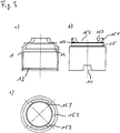
- the one-hand lever mixer cartridge selected as an embodiment consists essentially of a head piece 1, in which a spindle 2 projects axially, which is pivotally mounted in a rotatably mounted spindle receptacle 3 and engages in a slider 4 which is connected to a control disk 5 which is provided with a transmission disk 6 corresponds, which is sealed by a seal molding 7 against a bottom piece 8.
- the head piece 1 is sleeve-shaped and manufactured in the embodiment as a brass turned part. At its bottom piece 8 facing the end of the head piece 1 diametrically two rectangular recesses 11 are formed, which extend beyond an end on the inside of the head piece 1 introduced locking groove 12 addition. At its opposite end of the recesses 11, the head piece 1 a reduced diameter portion 15, in which approximately centrally a circumferential groove 150 is formed and the end with a circumferential nose 151 is provided. In the reduced diameter portion 15, two recesses 152 are diametrically opposed to each other, which extend up to the circumferential groove 150 and are formed by the respective two radial stops 153. The stops 153 are used to limit the rotation of the spindle receptacle 3.
- the recesses may be designed as a bore into which the axle pin 23 of the spindle 2 engages, whereby rotation of the spindle holder 3 is blocked.
- a fastening ring 16 is further turned up.
- the mounting ring 16 has circumferentially outside an external thread 161 for screwing into a valve 9.
- a reduced-diameter portion 162 is formed, through which a stop 163 is formed.
- the reduced diameter portion 162 is provided with an external hexagon 164.
- the diameter reduced Section 162 opposite end is further formed inside the mounting ring 16 circumferentially a nose 165.
- the spindle 2 is formed in the embodiment substantially cuboid. Approximately in the middle of the spindle 2, an annular coaxial Anformung 21 for receiving a - not shown - keypad formed. Below the Anformung 21 is introduced through the spindle 2, a bore 22 for receiving an axle pin 23. At the end, a control head 24 designed in the form of a spherical disk is integrally formed on the spindle 2 and is flattened on its side facing the slider 4.
- the spindle receptacle 3 is formed as a substantially cylindrical plastic injection molded part.
- a two-step shoulder 31 is integrally formed on the spindle receptacle 3, the contour of which corresponds to the inner contour of the two-step shoulder 14 of the head piece 1 against which it bears.
- a radial through hole 32 for receiving the axle pin 23 for the spindle 2 is introduced through the spindle receptacle 3.
- Axial is formed by the spindle holder 3, a passage 33 for the spindle 2, which has lateral stops 34, by which the pivot radius of the spindle 2 is limited to the axle pin 23.
- the passage 33 terminates in a substantially parallelepiped-shaped receptacle 35 for the slider 4.
- the designed as a plastic injection molded slider 4 is formed substantially in the form of a circular disc on which a substantially cuboidal shaped piece 41 is formed.
- the molding 41 is formed such that it is guided in the longitudinal direction of the receptacle 35 of the spindle receptacle 3 and in the transverse direction. Axial is through the slider 4, the fitting 41 penetrating a slot 42 for receiving the control head 24 of the spindle 2 introduced.
- On its underside which faces the fitting 41 three axial webs 43 for receiving the control disk 5 are formed on the outside of the slider 4.
- the control disk 5 is oval and made as a ceramic part. On its side facing the transmission disk 6, the control disk has a centrally arranged, egg-shaped indentation 51. On its upper side opposite the indentation 51, three recesses 52 for receiving the webs 23 of the sliding piece 4 are further circumferentially recirculated in the control disk 5. About the recesses 52, the control disk 5 is positively connected to the slider 4.
- the transmission disk 6 is also designed as a ceramic part. Through the pass-through disk 6, two inlet channels 61 for cold or hot water and a relatively enlarged outlet channel 62 for the mixed water are introduced. The inlet channels 61 and the outlet channel 62 are led obliquely to the aperture 6 through this. The side offset from each other on the transmission disc 6 three recesses 63 for positive connection with the bottom piece 8 are introduced.
- the seal molding 7 is made in the embodiment of rubber.
- the seal molding 7 is essentially formed by three rings 71, which are formed in each case on the two remaining rings 71, so that a cloverleaf-like contour is formed.
- On the rings 71 of the sealing molding 7 each sealing lips 72 are integrally formed on the upper side and on the underside thereof.
- To stabilize the shape of the rings 71 are each provided with a support ring 73 which is disposed between the sealing lips 72 of the rings 71.
- the bottom piece 8 is substantially cylindrical.
- two inlet bores 81 and an outlet hole 82 are introduced, the center axes define an isosceles triangle, such that the holes merge into each other, so that a cloverleaf-like receptacle 83 is formed for the seal molding 7.
- two positioning pins 84 are integrally formed in the head piece for engagement with correspondingly corresponding positioning bores 95 of a fitting 9.
- two rectangular tabs 85 are integrally formed on the bottom piece 8 for engagement in the recesses 11 of the head piece 1.
- locking lugs 86 are further integrally formed for engagement in the locking groove 12 of the head piece 1.
- lugs 88 are integrally formed on two webs, which engage in corresponding recesses 63 of the transmission disk 6.
- FIG. 15 an example of a fitting 9 for receiving the cartridge described above is shown.
- the valve is essentially cylindrical and has a cartridge receptacle 91, at the open end of which an internal thread 92 for screwing in the fastening ring 16 of the head piece 1 is introduced.
- the cartridge receptacle 91 open on the bottom side two water inlet connections 93 and a water outlet port 94, the center axes of an isosceles triangle bre grenz.
- a positioning hole 95 for receiving the positioning pins 852 of the bottom piece 8 is introduced in each case.
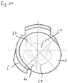
- FIGS. 9 to 11 different positions of the disk control formed from the control disk 5 and the transmission disk 6 are shown schematically.
- none of the inlet channels 61 of the passage disc 6 is covered by the indentation 51 of the control disk 5.
- the inlet channels 61 are thus closed by the control disk 5. There is no water flow (closed position).
- FIG. 2 is the arrangement with the disk control according to FIG. 10 shown.
- the mixed water exits from the outlet channel 82 of the bottom piece 8 and, in the mounted state, in which the positioning pins 84 of the bottom piece 8 engage in the positioning holes 95 of the fitting 9, in the water outlet port 94 of the valve 9, whereby a bottom water removal is possible.
- the mixer cartridge is connected via the mounting ring 16 with the valve 9 and biased against the bottom of the cartridge holder 91.
- This achieved bias forces cause a balance of manufacturing tolerances of the individual components, in particular on slider 4, control disk 5, Passage disk 6 and bottom piece 8. This conditionally, it can lead to an uneven contact pressure between the passage disk 6 on one side and the bottom piece 8 on the other side of the seal molding 7. Due to the elastic design of the seal molding 7 with the integrally formed on this sealing lips 72 a positional adjustment of the seal molding 7 within the receptacle 88 of the bottom piece 8 is made possible, whereby a reliable sealing effect is ensured.
- the mounting ring 16 is slipped over the reduced diameter portion 15 of the head piece 1, wherein the circumferential nose 151 is forced inwardly when passing the circumferential nose 165 of the mounting ring 16 inwardly. After passing through the nose 165 of the mounting ring 16, the nose 151 of the reduced-diameter portion 15 of the head piece 1 resumes its original position. The mounting ring 16 is thus held captive on the head piece 1. The screwing of the mounting ring 16 via the hexagon socket 164th
Abstract
Description
- Die Erfindung betrifft eine Einhandhebelmischerkartusche, umfassend ein Kopfstück, das ein wenigstens einen Zulaufkanal und wenigstens einen Ablaufkanal aufweisendes Bodenstück aufnimmt, sowie eine Scheibensteuerung mit einer Steuerscheibe, welche über eine zumindest schwenkbar gelagerte Spindel relativ zu einer drehfest angeordneten Durchlassscheibe verschiebbar ist.
- In Sanitärarmaturen werden häufig Mischerkartuschen eingesetzt, in denen eine eine Steuerscheibe sowie eine Durchlassscheibe aufweisende Scheibensteuerung angeordnet ist, welche über einen einzigen Hebel derart bedienbar ist, dass sowohl die Wassermenge, als auch die Wassertemperatur über ein und denselben Hebel steuerbar ist. Derartige austauschbare Kartuschen können in unterschiedlich gestalteten Armaturengehäusen eingesetzt werden. In einigen Anwendungsgebieten kommen auch modifizierte Kartuschen zum Einsatz, bei denen ein konstantes Mischungsverhältnis eingestellt ist, wobei die Drehbewegung des Hebels blockiert ist, sodass nur über die Schwenkbewegung des Hebels eine Einstellung der Wassermenge erfolgen kann. Diese Ausführung kommt auch in solchen Anwendungsgebieten zum Einsatz, in denen nur ein Zulaufkanal in der Armatur vorhanden ist.
- Bei der Gestaltung von Armaturengehäusen besteht zunehmend der Wunsch nach einem möglichst kleinen Aufbau. Daher ist es erforderlich, die Mischerkartuschen klein und kompakt aufzubauen, wobei gleichzeitig die Anforderung nach einer großen Wassermenge gegeben ist. Mischerkartuschen sind regelmäßig aus Kunststoffspritzgussteilen zusammengesetzt, wobei aufgrund der kleinen Dimensionierung der Bauteile, verbunden mit großzügig dimensionierten Durchlassöffnungen für den Wasserdurchtritt bereichsweise nur geringe Materialstärken vorhanden sind. Gleichzeitig bestehen hohe Anforderungen an die Dichtheit der Mischerkartuschen. Hierzu kommen überstehende Flachdichtungen oder auch O-Ringe zum Einsatz. Die Dichtwirkung wird über eine Verspannung der Mischerkartusche gegen den Grund einer Armatur bewirkt.
- Mischerkartuschen der vorgenannten Art bestehen aus vielen Einzelteilen, die jeweils bestimmte Fertigungstoleranzen aufweisen. In ungünstigen Fällen kann dies zu einem ungleichmäßigen Andruck der eingesetzten Dichtungen kommen, was zu Beeinträchtigungen der Dichtwirkung führen kann.
- Hier will die Erfindung Abhilfe schaffen. Der Erfindung liegt die Aufgabe zugrunde, eine Einhandhebelmischerkartusche der vorgenannten Art zu schaffen, bei der auch bei ungünstigen Additionen von Fertigungstoleranzen und hierdurch bewirkten ungleichmäßigen Andruckkräften eine zuverlässige Dichtwirkung gewährleistet ist. Gemäß der Erfindung wird diese Aufgabe durch die Merkmale des kennzeichnenden Teils des Patentanspruchs 1 gelöst.
- Mit der Erfindung ist eine Einhandhebelmischerkartusche geschaffen, bei der auch bei ungünstigen Additionen von Fertigungstoleranzen und hierdurch bewirkten ungleichmäßigen Andruckkräften eine zuverlässige Dichtwirkung gewährleistet ist. Durch den Einsatz von Lippendichtungen ist eine Aufnahme von Fertigungstoleranzen und somit ein Ausgleich von Andruckdifferenzen ermöglicht, wodurch die Dichtwirkung gewährleistet ist.
- In Weiterbildung der Erfindung sind zwei Zulaufkanäle und ein Ablaufkanal derart angeordnet, dass ihre Mittelachsen ein gleichschenkliges Dreieck begrenzen. Durch die regelmäßige Anordnung der Kanäle und somit auch der diese umgebenden Dichtungen ist eine gleichmäßige Anpressdruckverteilung erzielt.
- In Ausgestaltung der Erfindung ist ein flexibles Formteil angeordnet, das wenigstens zwei Durchführungen aufweist und an dem die wenigstens zwei Durchführungen umgebend jeweils zumindest eine, vorzugsweise zwei gegenüberliegend angeordnete ringförmige Lippendichtungen angeformt sind. Vorzugsweise weist das flexible Formteil drei Durchführungen auf, deren Mittelachsen ein gleichschenkliges Dreieck begrenzen. Bevorzugt ist das flexible Formteil aus Gummi hergestellt.
- In weiterer Ausgestaltung der Erfindung ist das flexible Formteil im Wesentlichen durch drei Ringe gebildet, die jeweils an den beiden übrigen Ringen angeformt sind. Hierdurch ist eine kleeblattartige Kontur gebildet, welche eine platzsparende Dichtungsanordnung bewirkt.
- In Weiterbildung der Erfindung ist in die Durchführungen des flexiblen Formteils jeweils ein Stützring eingebracht. Hierdurch ist eine Formänderung der Durchführungen bzw. der Ringe des Dichtungsformteils, welche zu einer Beeinträchtigung der Dichtwirkung führen könnten, verhindert.
- In weiterer Ausgestaltung der Erfindung ist in dem Bodenstück eine Ausnehmung eingebracht, deren Innenkontur im Wesentlichen der Außenkontur des flexiblen Formstücks entspricht. Hierdurch ist eine formstabile Lage des Formstücks erzielt.
- Vorteilhaft ist an dem Bodenstück zumindest Abschnittsweise umlaufend ein Rand angeformt, der die Durchlassscheibe drehfest an der wenigstens einen Lippendichtung anliegend aufnimmt. Hierdurch ist die Lage des Formstücks weiter verbessert.
- In weiterer Ausgestaltung der Erfindung ist das Kopfstück aus Metall, vorzugsweise aus Messing hergestellt. Hierdurch ist eine Verformung des Kopfstücks durch die Vorspannung der Mischerkartusche gegen die Armatur auch über einen langen Zeitraum verhindert.
- Bevorzugt ist das Bodenstück aus Kunststoff hergestellt. Hierdurch ist eine kostengünstige Herstellung des in seiner Form komplex ausgestalteten Bodenstücks ermöglicht.
- Andere Weiterbildungen und Ausgestaltungen der Erfindung sind in den übrigen Unteransprüchen angegeben. Ein Ausführungsbeispiel der Erfindung ist in den Zeichnungen dargestellt und wird nachfolgend im Einzelnen beschrieben. Es zeigen:
- Figur 1
- die schematische Darstellung einer Einhandhebelmischerkartusche (geschlossene Stellung)
- a) in der Ansicht von unten,
- b) im Längsschnitt,
- c) in der Draufsicht;
- Figur 2
- die Einhandhebelmischerkartusche aus
Figur 1 in geöffneter Stellung (ohne Befestigungsring)- a) in der Ansicht von unten,
- b) im Längsschnitt;
- Figur 3
- die schematische Darstellung des Kopfstücks der Mischerkartusche aus
Figur 1 - a) im Längsschnitt
- b) in der Seitenansicht (um 90° verdreht),
- c) im Querschnitt;
- Figur 4
- die Darstellung des Bodenstücks der Mischerkartusche aus
Figur 1 - a) in der Draufsicht,
- b) im Schnitt A-A der Darstellung aus a),
- c) im Schnitt B-B der Darstellung aus a),
- d) im Längsschnitt,
- e) in der Seitenansicht,
- f) in der Ansicht von unten;
- Figur 5
- die Darstellung des Lippendichtungsformteils der Mischerkartusche aus
Figur 1 - a) in der Draufsicht,
- b) im Schnitt A-A der Darstellung aus a),
- c) im Schnitt B-B der Darstellung aus a),
- d) im Querschnitt;
- Figur 6
- die Darstellung der Durchlassscheibe der Mischerkartusche aus
Figur 1 - a) in der Ansicht von unten,
- b) im Querschnitt,
- c) in der Draufsicht;
- Figur 7
- die Darstellung der Steuerscheibe der Mischerkartusche aus
Figur 1 - a) in der Ansicht von unten,
- b) im Querschnitt,
- c) in der Draufsicht;
- Figur 8
- die Darstellung des Gleitstücks der Mischerkartusche aus
Figur 1 - a) in der Ansicht von unten,
- b) im Querschnitt,
- c) in der Draufsicht;
- Figur 9
- die Scheibensteuerung der Mischerkartusche aus
Figur 1 mit Steuerscheibe und Durchlassscheibe in der Position "geschlossen"; - Figur 10
- die Scheibensteuerung aus
Figur 9 in der Position "Mischwasser"; - Figur 11
- die Scheibensteuerung aus
Figur 9 in der Position "Kaltwasser"; - Figur 12
- die Spindelaufnahme der Mischerkartusche aus
Figur 1 - a) in der Ansicht von unten,
- b) im Querschnitt,
- c) in der Draufsicht;
- Figur 13
- die Spindel der Mischerkartusche aus
Figur 1 - a) in der Seitenansicht,
- b) in der Vorderansicht,
- c) in der Draufsicht;
- Figur 14
- den Befestigungsring der Mischerkartusche aus
Figur 1 - a) in Schnittdarstellung,
- b) in der Draufsicht und
- Figur 15
- eine Armatur zur Aufnahme der Mischerkartusche aus
Figur 1 - a) in der Ansicht von unten,
- b) in Schnittdarstellung,
- c) in der Draufsicht.
- Die als Ausführungsbeispiel gewählte Einhandhebelmischerkartusche besteht im Wesentlichen aus einem Kopfstück 1, in das eine Spindel 2 axial hineinragt, die in einer drehbar gelagerten Spindelaufnahme 3 schwenkbar gelagert ist und in ein Gleitstück 4 eingreift, das mit einer Steuerscheibe 5 verbunden ist, die mit einer Durchlassscheibe 6 korrespondiert, welche über ein Dichtungsformteil 7 gegen ein Bodenstück 8 abgedichtet ist.
- Das Kopfstück 1 ist hülsenartig ausgebildet und im Ausführungsbeispiel als Messingdrehteil hergestellt. An seinen dem Bodenstück 8 zugewandten Ende sind an dem Kopfstück 1 diametral zueinander zwei rechteckförmige Aussparungen 11 angeformt, die sich über eine endseitig an der Innenseite des Kopfstücks 1 eingebrachte Rastnut 12 hinaus erstrecken. An seinem den Aussparungen 11 gegenüberliegenden Ende weist das Kopfstück 1 einen durchmesserreduzierter Abschnitt 15 auf, in dem etwa mittig eine umlaufende Nut 150 eingeformt ist und der endseitig mit einer umlaufenden Nase 151 versehen ist. In den durchmesserreduzierten Abschnitt 15 sind diametral zueinander zwei Ausnehmungen 152 eingebracht, die sich bis zu der umlaufenden Nut 150 erstrecken und durch die jeweils zwei radiale Anschläge 153 gebildet sind. Die Anschläge 153 dienen der Drehbegrenzung der Spindelaufnahme 3. Innen ist durch den durchmesserreduzierten Abschnitt ein Absatz 14 gebildet. Für Ausführungsformen, bei denen das Mischungsverhältnis konstant eingestellt sein soll, können die Ausnehmungen als Bohrung ausgeführt sein, in die der Achsstift 23 der Spindel 2 eingreift, wodurch eine Drehung der Spindelaufnahme 3 blockiert ist.
- Auf den durchmesserreduzierten Abschnitt 15 des Kopfstücks 1 ist weiterhin ein Befestigungsring 16 aufgestülpt. Der Befestigungsring 16 weist außen umlaufend ein Außengewinde 161 zum Einschrauben in eine Armatur 9 auf. Oberhalb des Außengewindes 161 ist ein durchmesserreduzierter Abschnitt 162 angeformt, durch den ein Anschlag 163 gebildet ist. Außen ist der durchmesserreduzierte Abschnitt 162 mit einem Außensechskant 164 versehen. An seinem dem durchmesserreduzierten Abschnitt 162 entgegengesetzten Ende ist innen in dem Befestigungsring 16 weiterhin umlaufend eine Nase 165 angeformt.
- Die Spindel 2 ist im Ausführungsbeispiel im Wesentlichen quaderförmig ausgebildet. Etwa mittig ist an der Spindel 2 eine kreisringförmige koaxiale Anformung 21 zur Aufnahme eines - nicht dargestellten - Bedienteils angeformt. Unterhalb der Anformung 21 ist durch die Spindel 2 eine Bohrung 22 zur Aufnahme eines Achsstiftes 23 eingebracht. Endseitig ist an die Spindel 2 ein in Form einer Kugelscheibe ausgebildeter Steuerkopf 24 angeformt, der an seiner dem Gleitstück 4 zugewandten Seite abgeflacht ausgebildet ist.
- Die Spindelaufnahme 3 ist als im Wesentlichen zylinderförmiges Kunststoffspritzgussteil ausgebildet. An seinem dem Gleitstück 4 zugewandten Ende ist an der Spindelaufnahme 3 ein zweistufiger Absatz 31 angeformt, dessen Kontur der Innenkontur des zweistufigen Absatzes 14 des Kopfstücks 1 entspricht, an der dieser anliegt. Oberhalb des zweistufigen Absatzes 31 ist durch die Spindelaufnahme 3 eine radiale Durchgangsbohrung 32 zur Aufnahme des Achsstifts 23 für die Spindel 2 eingebracht. Axial ist durch die Spindelaufnahme 3 eine Durchführung 33 für die Spindel 2 eingeformt, welche seitliche Anschläge 34 aufweist, durch die der Schwenkradius der Spindel 2 um den Achsstift 23 begrenzt ist. Die Durchführung 33 mündet in einer im Wesentlichen quaderförmig ausgebildeten Aufnahme 35 für das Gleitstück 4.
- Das als Kunststoffspritzgußteil ausgeführte Gleitstück 4 ist im Wesentlichen in Form einer Kreisscheibe ausgebildet, auf der ein im Wesentlichen quaderförmiges Formstück 41 angeformt ist. Das Formstück 41 ist derart ausgebildet, dass es innerhalb der Aufnahme 35 der Spindelaufnahme 3 in Längsrichtung verschiebbar und in Querrichtung geführt ist. Axial ist durch das Gleitstück 4 das Formstück 41 durchdringend ein Langloch 42 zur Aufnahme des Steuerkopfes 24 der Spindel 2 eingebracht. An seiner dem Formstück 41 entgegengerichteten Unterseiten sind an dem Gleitstück 4 außen umlaufend weiterhin drei axiale Stege 43 zur Aufnahme der Steuerscheibe 5 angeformt.
- Die Steuerscheibe 5 ist oval ausgebildet und als Keramikteil hergestellt. An seiner der Durchlassscheibe 6 zugewandten Seite weist die Steuerscheibe eine mittig angeordnete, eiförmige Einbuchtung 51 auf. Auf seiner der Einbuchtung 51 entgegengesetzten Oberseite sind in der Steuerscheibe 5 außen umlaufend weiterhin drei Ausnehmungen 52 zur Aufnahme der Stege 23 des Gleitstücks 4 eingebracht. Über die Ausnehmungen 52 ist die Steuerscheibe 5 mit dem Gleitstück 4 formschlüssig verbunden.
- Die Durchlassscheibe 6 ist ebenfalls als Keramikteil ausgeführt. Durch die Durchlassscheibe 6 sind zwei Einlasskanäle 61 für kaltes bzw. warmes Wasser sowie ein relativ zu diesen vergrößert ausgebildeter Auslasskanal 62 für das Mischwasser eingebracht. Die Einlasskanäle 61 sowie der Auslasskanal 62 sind schräg zur Durchlassscheibe 6 durch diese hindurchgeführt. Seitlich sind an der Durchlassscheibe 6 versetzt zueinander drei Aussparungen 63 zur formschlüssigen Verbindung mit dem Bodenstück 8 eingebracht.
- Das Dichtungsformteil 7 ist im Ausführungsbeispiel aus Gummi hergestellt. Das Dichtungsformteil 7 ist im Wesentlichen durch drei Ringe 71 gebildet, die jeweils an den beiden übrigen Ringen 71 angeformt sind, sodass eine kleeblattartige Kontur gebildet ist. An den Ringen 71 des Dichtungsformteils 7 sind an deren Oberseite sowie an deren Unterseite jeweils Dichtlippen 72 angeformt. Zur Formstabilisierung sind die Ringe 71 jeweils mit einem Stützring 73 versehen, welcher zwischen den Dichtlippen 72 der Ringe 71 angeordnet ist.
- Das Bodenstück 8 ist im Wesentlichen zylinderförmig ausgebildet. In dem Bodenstück 8 sind zwei Einlassbohrungen 81 sowie eine Auslassbohrung 82 eingebracht, deren Mittelachsen ein gleichschenkliges Dreieck begrenzen, derart, dass die Bohrungen ineinander übergehen, sodass eine kleeblattartige Aufnahme 83 für das Dichtungsformteil 7 gebildet ist. An seiner dem Kopfstück 1 abgewandten Unterseite sind in dem Kopfstück zwei Positionierstifte 84 zum Eingriff in mit diesen korrespondierende Positionierbohrungen 95 einer Armatur 9 angeformt. Seitlich sind an dem Bodenstück 8 diametral zueinander zwei rechteckförmige Nasen 85 zum Eingriff in die Aussparungen 11 des Kopfstücks 1 angeformt. Seitlich der Nasen 85 sind weiterhin Rastnasen 86 zum Eingriff in die Rastnut 12 des Kopfstücks 1 angeformt. Diese Rastnasen 86 ermöglichen eine Rastverbindung zwischen dem Bodenstück 8 und dem Kopfstück 1.
- Umlaufend der kleeblattartige Aufnahme 83 sind gleichmäßig beabstandet zueinander drei Stege 87 zur drehfesten Aufnahme der Durchlassscheibe 6 angeformt. Die Stege 87 greifen in die Aussparungen 63 der Durchlassscheibe 6 ein. Zur Verbesserung des Formschlusses sind an zwei Stegen 87 Nasen 88 angeformt, welche in hierzu korrespondierende Aussparungen 63 der Durchlassscheibe 6 eingreifen.
- In
Figur 15 ist beispielhaft eine Armatur 9 zur Aufnahme der zuvor beschriebenen Kartusche dargestellt. Die Armatur ist im Wesentlichen zylinderförmig ausgebildet und weist eine Kartuschenaufnahme 91 auf, an deren offenen Ende ein Innengewinde 92 zum Einschrauben des Befestigungsrings 16 des Kopfstücks 1 eingebracht ist. In die Kartuschenaufnahme 91 münden bodenseitig zwei Wasserzulaufanschlüsse 93 sowie ein Wasserablaufanschluss 94, deren Mittelachsen ein gleichschenkliges Dreieck bregrenzen. Beidseitig des Wasserablaufanschlusses 94 ist jeweils eine Positionierbohrung 95 zur Aufnahme der Positionierstifte 852 des Bodenstücks 8 eingebracht. - In
Figuren 9 bis 11 sind verschiedene Stellungen der aus der Steuerscheibe 5 und der Durchlassscheibe 6 gebildeten Scheibensteuerung schematisch dargestellt. In der Stellung gemäßFigur 9 ist keiner der Einlasskanäle 61 der Durchlassscheibe 6 von der Einbuchtung 51 der Steuerscheibe 5 überdeckt. Die Einlasskanäle 61 sind somit durch die Steuerscheibe 5 verschlossen. Es findet kein Wasserdurchlauf statt (geschlossene Stellung). - In der Stellung der Scheibensteuerung gemäß
Figur 10 sind beide Einlasskanäle 61 für Warm- und Kaltwasser von der Einbuchtung 51 der Steuerscheibe 5 überdeckt, welche gleichzeitig auch den Auslasskanal 62 der Durchlassscheibe 6 überdeckt. Es findet eine Vermischung von Warm- und Kaltwasser innerhalb der Einbuchtung 51 der Steuerscheibe 5 statt, bevor das Mischwasser durch den Auslasskanal 62 der Durchlassscheibe 6 austritt. In der Position der Scheibensteuerung gemäßFigur 11 ist nur ein Einlasskanal 61 - hier der Kaltwasserzulauf - von der Einbuchtung 51 der Steuerscheibe 5 verdeckt, die diesen Einlasskanal 61 mit dem Auslasskanal 62 der Durchlassscheibe 6 verbindet. Es tritt somit nur Kaltwasser aus dem Auslasskanal 82 des Bodenstücks 8 aus. - In
Figur 2 ist die Anordnung mit der Scheibensteuerung gemäßFigur 10 gezeigt. Das Mischwasser tritt aus dem Auslasskanal 82 des Bodenstücks 8 aus und gelangt in montierten Zustand, bei dem die Positionierstifte 84 des Bodenstücks 8 in die Positionierbohrungen 95 der Armatur 9 eingreifen, in den Wasserablaufanschluss 94 der Armatur 9, wodurch eine bodenseitige Wasserentnahme ermöglicht ist. - Die Steuerung des aus der Auslaufsbohrung 82 des Bodenstücks 8 austretenden Wasserflusses erfolgt über die Spindel 2. Ein Verschwenken der Spindel 2 um den Achsstift 23 wird über den Steuerkopf 24 auf das Gleitstück 4 sowie auf die mit dem Gleitstück 4 formschlüssig verbundene Steuerscheibe 5 übertragen, wodurch eine Steuerung der Wassermenge bewirkt ist. Eine Drehung der Spindel 2 wird über den Achsstift 23 auf die in dem Kopfstück 1 drehbar gelagerte Spindelaufnahme 3 übertragen, welche mit dem Gleitstück 4 über das Formstück 41 formschlüssig verbunden ist. Hierdurch wird die Drehbewegung auf das Gleitstück 4 und somit auf die mit diesem formschlüssig verbundene Steuerscheibe 5 übertragen und bewirkt eine Einstellung des Mischverhältnisses der an den Einlasskanälen 61 der Durchlassscheibe 6 anliegenden Wasserströme.
- Die Mischerkartusche wird über den Befestigungsring 16 mit der Armatur 9 verbunden und gegen den Boden der Kartuschenaufnahme 91 vorgespannt. Hierdurch erzielte Vorspannungskräfte bewirken einen Ausgleich von Fertigungstoleranzen der einzelnen Bauteile, insbesondere an Gleitstück 4, Steuerscheibe 5, Durchlassscheibe 6 und Bodenstück 8. Hierdurch bedingt kann es zu einem ungleichmäßigen Anpressdruck zwischen der Durchlassscheibe 6 auf der einen Seite sowie dem Bodenstück 8 auf der anderen Seite auf das Dichtungsformteil 7 kommen. Durch die elastische Ausbildung des Dichtungsformteils 7 mit den an diesem angeformten Dichtlippen 72 ist eine Lageangleichung des Dichtungsformteils 7 innerhalb der Aufnahme 88 des Bodenstücks 8 ermöglicht, wodurch eine zuverlässige Dichtwirkung gewährleistet ist. Effektiv wird durch die Durchgängigkeit der kleeblattförmigen Aufnahme 88 des Bodenstücks 8 eine Dichtwirkung des Dichtungsformteils 7 mit seinen an diesem angeformten Dichtlippen 72 zwischen den Einlass- bzw. Auslasskanälen 61, 62 der Durchlassscheibe 6 und den Wasserzulau- bzw. Wasserablaufanschlüssen 93, 94 der Armatur bewirkt. Die Dichtwirkung wird durch die mit Wasser hinterspülten Dichtlippen 72 unterstützt. Eine Formänderung der Ringe 71 des Dichtungsformteils 7, welche zu einer Beeinträchtigung der Dichtwirkung führen könnten, ist durch die in den Ringen 71 eingebrachten Stützringe 73 verhindert. Durch die Ausbildung des Kopfstücks 1 aus Messing sind Formänderungen des Kopfstücks 1 durch die Vorspannung insbesondere im Bereich des Bodenstücks 8 vermieden.
- Der Befestigungsring 16 ist auf den durchmesserreduzierten Abschnitt 15 des Kopfstücks 1 übergestülpt, wobei die umlaufende Nase 151 bei Passieren der umlaufenden Nase 165 des Befestigungsrings 16 elastisch nach innen gezwängt wird. Nach Passieren der Nase 165 des Befestigungsrings 16 nimmt die Nase 151 des durchmesserreduzierten Abschnitts 15 des Kopfstücks 1 ihre ursprüngliche Position wieder ein. Der Befestigungsring 16 ist somit verliersicher an dem Kopfstück 1 gehalten. Das Einschrauben des Befestigungsrings 16 erfolgt über den Außensechskant 164.
Claims (12)
- Einhandhebelmischerkartusche, umfassend ein Kopfstück (1), das ein wenigstens einen Zulaufkanal (81) und wenigstens einen Ablaufkanal (82) aufweisendes Bodenstück (8) aufnimmt, sowie eine Scheibensteuerung mit einer Steuerscheibe (5), welche über eine zumindest schwenkbar gelagerte Spindel (2) relativ zu einer drehfest angeordneten Durchlassscheibe (6) verschiebbar ist, dadurch gekennzeichnet, dass zumindest alle Zulaufkanäle (81) mit wenigstens einer Lippendichtung zur Abdichtung des Bodenstücks (8) gegenüber der Durchlassscheibe (6) und/oder gegenüber einer die Kartusche aufnehmenden Armatur (9) versehen sind.
- Einhandhebelmischerkartusche nach Anspruch 1, dadurch gekennzeichnet, dass das Bodenstück (8) wenigstens zwei Zulaufkanäle (81) aufweist und dass die Steuerscheibe (5) über eine drehbar und schwenkbar gelagerte Spindel (2) relativ zu einer drehfest angeordneten Durchlassscheibe (6) drehbar und verschiebbar ist.
- Einhandhebelmischerkartusche nach Anspruch 2, dadurch gekennzeichnet, dass zwei Zulaufkanäle (81) und ein Ablaufkanal (82) derart angeordnet sind, dass ihre Mittelachsen ein gleichschenkliges Dreieck begrenzen.
- Einhandhebelmischerkartusche nach einem der vorgenannten Ansprüche, dadurch gekennzeichnet, dass ein flexibles Formteil (7) angeordnet ist, das wenigstens zwei Durchführungen aufweist und an dem die wenigstens zwei Durchführungen umgebend jeweils zumindest eine, bevorzugt zwei gegenüberliegend angeordnete ringförmige Lippendichtungen angeformt sind.
- Einhandhebelmischerkartusche nach Anspruch 4, dadurch gekennzeichnet, dass das flexible Formteil (7) drei mit Lippendichtungen (72) versehene Durchführungen aufweist, deren Mittelachsen ein gleichschenkliges Dreieck begrenzen.
- Einhandhebelmischerkartusche nach Anspruch 5, dadurch gekennzeichnet, dass das flexible Formteil (7) im Wesentlichen durch drei Ringe (71) gebildet ist, die jeweils an den beiden übrigen Ringen (71) angeformt sind.
- Einhandhebelmischerkartusche nach Anspruch 5 oder 6, dadurch gekennzeichnet, dass in die Durchführungen des flexiblen Formteils (7) jeweils ein Stützring (73) eingebracht ist.
- Einhandhebelmischerkartusche nach einem der Ansprüche 5 bis 6, dadurch gekennzeichnet, dass in dem Bodenstück eine Ausnehmung (83) eingebracht ist, deren Innenkontur im Wesentlichen der Außenkontur des flexiblen Formstücks (7) entspricht.
- Einhandhebelmischerkartusche nach einem der vorgenannten Ansprüche, dadurch gekennzeichnet, dass an dem Bodenstück umlaufend wenigstens zwei Stege (87) angeformt sind, welche die Durchlassscheibe (6) drehfest an der wenigstens einen Lippendichtung anliegend aufnehmen.
- Einhandhebelmischerkartusche nach Anspruch 9, dadurch gekennzeichnet, dass an wenigstens einem der wenigstens zwei Stege (87) eine Nase (88) zur Fixierung der Durchlassscheibe (6) angeformt ist.
- Einhandhebelmischerkartusche nach einem der Ansprüche 4 bis 10, dadurch gekennzeichnet, dass das flexible Formteil (7) aus Gummi hergestellt ist.
- Einhandhebelmischerkartusche nach einem der vorgenannten Ansprüche, dadurch gekennzeichnet, dass das Kopfstück (1) aus Metall, vorzugsweise aus Messing hergestellt ist.
Priority Applications (5)
| Application Number | Priority Date | Filing Date | Title |
|---|---|---|---|
| ES12157387.7T ES2532773T3 (es) | 2012-02-28 | 2012-02-28 | Cartucho mezclador con palanca para una sola mano |
| EP12157387.7A EP2634464B1 (de) | 2012-02-28 | 2012-02-28 | Einhandhebelmischerkartusche |
| KR1020147022824A KR102045096B1 (ko) | 2012-02-28 | 2013-02-04 | 단일 레버 믹서 카트리지 |
| PCT/EP2013/052155 WO2013127600A1 (de) | 2012-02-28 | 2013-02-04 | Einhandhebelmischerkartusche |
| US14/377,596 US9931606B2 (en) | 2012-02-28 | 2013-02-04 | Single-lever mixing cartridge |
Applications Claiming Priority (1)
| Application Number | Priority Date | Filing Date | Title |
|---|---|---|---|
| EP12157387.7A EP2634464B1 (de) | 2012-02-28 | 2012-02-28 | Einhandhebelmischerkartusche |
Publications (2)
| Publication Number | Publication Date |
|---|---|
| EP2634464A1 true EP2634464A1 (de) | 2013-09-04 |
| EP2634464B1 EP2634464B1 (de) | 2014-12-24 |
Family
ID=47749774
Family Applications (1)
| Application Number | Title | Priority Date | Filing Date |
|---|---|---|---|
| EP12157387.7A Active EP2634464B1 (de) | 2012-02-28 | 2012-02-28 | Einhandhebelmischerkartusche |
Country Status (5)
| Country | Link |
|---|---|
| US (1) | US9931606B2 (de) |
| EP (1) | EP2634464B1 (de) |
| KR (1) | KR102045096B1 (de) |
| ES (1) | ES2532773T3 (de) |
| WO (1) | WO2013127600A1 (de) |
Families Citing this family (7)
| Publication number | Priority date | Publication date | Assignee | Title |
|---|---|---|---|---|
| DE202014101116U1 (de) * | 2014-03-12 | 2014-04-07 | Flühs Drehtechnik GmbH | Sanitärarmatur |
| DE202016101244U1 (de) * | 2016-03-08 | 2016-04-11 | Flühs Drehtechnik GmbH | Umstellventil |
| US11149418B2 (en) * | 2019-02-22 | 2021-10-19 | Brasstech, Inc. | Faucet handle hub |
| US20220325808A1 (en) * | 2021-04-08 | 2022-10-13 | Chunhe Qiu | Valve core assembly |
| US11614174B1 (en) | 2022-01-03 | 2023-03-28 | Chunhe Qiu | Fluid channel structure, valve core assembly and tap |
| US20220325809A1 (en) * | 2021-04-08 | 2022-10-13 | Chunhe Qiu | Valve core assembly |
| US11215289B1 (en) * | 2021-04-08 | 2022-01-04 | Chunhe Qiu | Valve core assembly |
Citations (5)
| Publication number | Priority date | Publication date | Assignee | Title |
|---|---|---|---|---|
| EP0075323A1 (de) * | 1981-09-23 | 1983-03-30 | FRIEDRICH GROHE ARMATURENFABRIK GmbH & CO | Dichtungsanordnung für den Anschluss von Keramikventilgliedern |
| DE3244120A1 (de) * | 1982-11-29 | 1984-05-30 | Friedrich Grohe Armaturenfabrik Gmbh & Co, 5870 Hemer | Dichtung oder anschlussdichtung fuer sanitaere mischventile |
| EP0590427A1 (de) * | 1992-09-29 | 1994-04-06 | AMFAG S.r.l. | Dichtung für Wasserein- und -auslassöffnungen in einem Einhebelmischer für warmes und kaltes Wasser |
| EP0637709A1 (de) * | 1993-08-02 | 1995-02-08 | Compania Roca-Radiadores, S.A. | Verbesserter Einhebel-Mischventil |
| EP1310711A2 (de) * | 2001-11-12 | 2003-05-14 | Friedrich Grohe AG & Co. KG | Wassermischventil |
Family Cites Families (1)
| Publication number | Priority date | Publication date | Assignee | Title |
|---|---|---|---|---|
| BRPI1013169A2 (pt) | 2009-02-27 | 2016-05-10 | Masco Corp | múltiplas torneiras |
-
2012
- 2012-02-28 EP EP12157387.7A patent/EP2634464B1/de active Active
- 2012-02-28 ES ES12157387.7T patent/ES2532773T3/es active Active
-
2013
- 2013-02-04 US US14/377,596 patent/US9931606B2/en active Active
- 2013-02-04 KR KR1020147022824A patent/KR102045096B1/ko active IP Right Grant
- 2013-02-04 WO PCT/EP2013/052155 patent/WO2013127600A1/de active Application Filing
Patent Citations (5)
| Publication number | Priority date | Publication date | Assignee | Title |
|---|---|---|---|---|
| EP0075323A1 (de) * | 1981-09-23 | 1983-03-30 | FRIEDRICH GROHE ARMATURENFABRIK GmbH & CO | Dichtungsanordnung für den Anschluss von Keramikventilgliedern |
| DE3244120A1 (de) * | 1982-11-29 | 1984-05-30 | Friedrich Grohe Armaturenfabrik Gmbh & Co, 5870 Hemer | Dichtung oder anschlussdichtung fuer sanitaere mischventile |
| EP0590427A1 (de) * | 1992-09-29 | 1994-04-06 | AMFAG S.r.l. | Dichtung für Wasserein- und -auslassöffnungen in einem Einhebelmischer für warmes und kaltes Wasser |
| EP0637709A1 (de) * | 1993-08-02 | 1995-02-08 | Compania Roca-Radiadores, S.A. | Verbesserter Einhebel-Mischventil |
| EP1310711A2 (de) * | 2001-11-12 | 2003-05-14 | Friedrich Grohe AG & Co. KG | Wassermischventil |
Also Published As
| Publication number | Publication date |
|---|---|
| US20150055433A1 (en) | 2015-02-26 |
| KR20140126713A (ko) | 2014-10-31 |
| EP2634464B1 (de) | 2014-12-24 |
| ES2532773T3 (es) | 2015-03-31 |
| US9931606B2 (en) | 2018-04-03 |
| WO2013127600A1 (de) | 2013-09-06 |
| KR102045096B1 (ko) | 2019-11-14 |
Similar Documents
| Publication | Publication Date | Title |
|---|---|---|
| EP2634464B1 (de) | Einhandhebelmischerkartusche | |
| DE60209666T2 (de) | Vierteldrehungsthermostatischekartusche mit konzentrischem Antrieb, mit keramischen Scheiben, und eine Mischbatterie die diese enthält | |
| EP2634463B1 (de) | Einhandhebelmischerkartusche | |
| DE3419209A1 (de) | Mischventil | |
| EP1696158A1 (de) | Ventiloberteil | |
| EP2771600B1 (de) | Einhandhebelmischerkartusche | |
| DE60022787T2 (de) | Mehrwegventil | |
| DE102006009665B4 (de) | Drosselventil | |
| EP2962020B1 (de) | Einhandhebelkartusche | |
| EP0060529B1 (de) | Mehrwegeventil mit einem Eingang und mindestens zwei Ausgängen, vorzugsweise Vierwegeventil | |
| DE102012102213A1 (de) | Luftsteuerventil | |
| DE2732672C2 (de) | Kugelhahn | |
| DE202012100687U1 (de) | Einhandhebelmischerkartusche | |
| DE3941106C2 (de) | Sanitäre Mischbatterie für den Wandanschluß | |
| DE202013104200U1 (de) | Einhandhebelkartusche | |
| EP2990125A1 (de) | Sanitärbrause | |
| WO2016016180A1 (de) | Ventil für einen fluidkreislauf eines kraftfahrzeugs | |
| DE10305394A1 (de) | Flüssigkeitsventil für Heiz- und/oder Kühlanlagen | |
| EP2962021B1 (de) | Einhandhebelkartusche | |
| DE202012100686U1 (de) | Einhandhebelmischerkartusche | |
| EP1632702B1 (de) | Mischventil | |
| DE202013100899U1 (de) | Einhandhebelkartusche | |
| WO2016135153A1 (de) | Ventiloberteil | |
| EP3064812B1 (de) | Einhandhebelkartusche | |
| EP3001081A1 (de) | Eckventil mit Handrad |
Legal Events
| Date | Code | Title | Description |
|---|---|---|---|
| PUAI | Public reference made under article 153(3) epc to a published international application that has entered the european phase |
Free format text: ORIGINAL CODE: 0009012 |
|
| 17P | Request for examination filed |
Effective date: 20121224 |
|
| AK | Designated contracting states |
Kind code of ref document: A1 Designated state(s): AL AT BE BG CH CY CZ DE DK EE ES FI FR GB GR HR HU IE IS IT LI LT LU LV MC MK MT NL NO PL PT RO RS SE SI SK SM TR |
|
| AX | Request for extension of the european patent |
Extension state: BA ME |
|
| GRAP | Despatch of communication of intention to grant a patent |
Free format text: ORIGINAL CODE: EPIDOSNIGR1 |
|
| INTG | Intention to grant announced |
Effective date: 20140922 |
|
| GRAS | Grant fee paid |
Free format text: ORIGINAL CODE: EPIDOSNIGR3 |
|
| GRAA | (expected) grant |
Free format text: ORIGINAL CODE: 0009210 |
|
| AK | Designated contracting states |
Kind code of ref document: B1 Designated state(s): AL AT BE BG CH CY CZ DE DK EE ES FI FR GB GR HR HU IE IS IT LI LT LU LV MC MK MT NL NO PL PT RO RS SE SI SK SM TR |
|
| REG | Reference to a national code |
Ref country code: GB Ref legal event code: FG4D Free format text: NOT ENGLISH |
|
| REG | Reference to a national code |
Ref country code: CH Ref legal event code: EP |
|
| REG | Reference to a national code |
Ref country code: IE Ref legal event code: FG4D Free format text: LANGUAGE OF EP DOCUMENT: GERMAN |
|
| REG | Reference to a national code |
Ref country code: AT Ref legal event code: REF Ref document number: 703337 Country of ref document: AT Kind code of ref document: T Effective date: 20150115 |
|
| REG | Reference to a national code |
Ref country code: DE Ref legal event code: R096 Ref document number: 502012001880 Country of ref document: DE Effective date: 20150219 |
|
| REG | Reference to a national code |
Ref country code: ES Ref legal event code: FG2A Ref document number: 2532773 Country of ref document: ES Kind code of ref document: T3 Effective date: 20150331 |
|
| REG | Reference to a national code |
Ref country code: NL Ref legal event code: VDEP Effective date: 20141224 |
|
| PG25 | Lapsed in a contracting state [announced via postgrant information from national office to epo] |
Ref country code: LT Free format text: LAPSE BECAUSE OF FAILURE TO SUBMIT A TRANSLATION OF THE DESCRIPTION OR TO PAY THE FEE WITHIN THE PRESCRIBED TIME-LIMIT Effective date: 20141224 Ref country code: NO Free format text: LAPSE BECAUSE OF FAILURE TO SUBMIT A TRANSLATION OF THE DESCRIPTION OR TO PAY THE FEE WITHIN THE PRESCRIBED TIME-LIMIT Effective date: 20150324 Ref country code: FI Free format text: LAPSE BECAUSE OF FAILURE TO SUBMIT A TRANSLATION OF THE DESCRIPTION OR TO PAY THE FEE WITHIN THE PRESCRIBED TIME-LIMIT Effective date: 20141224 |
|
| REG | Reference to a national code |
Ref country code: LT Ref legal event code: MG4D |
|
| PG25 | Lapsed in a contracting state [announced via postgrant information from national office to epo] |
Ref country code: LV Free format text: LAPSE BECAUSE OF FAILURE TO SUBMIT A TRANSLATION OF THE DESCRIPTION OR TO PAY THE FEE WITHIN THE PRESCRIBED TIME-LIMIT Effective date: 20141224 Ref country code: RS Free format text: LAPSE BECAUSE OF FAILURE TO SUBMIT A TRANSLATION OF THE DESCRIPTION OR TO PAY THE FEE WITHIN THE PRESCRIBED TIME-LIMIT Effective date: 20141224 Ref country code: SE Free format text: LAPSE BECAUSE OF FAILURE TO SUBMIT A TRANSLATION OF THE DESCRIPTION OR TO PAY THE FEE WITHIN THE PRESCRIBED TIME-LIMIT Effective date: 20141224 Ref country code: GR Free format text: LAPSE BECAUSE OF FAILURE TO SUBMIT A TRANSLATION OF THE DESCRIPTION OR TO PAY THE FEE WITHIN THE PRESCRIBED TIME-LIMIT Effective date: 20150325 Ref country code: HR Free format text: LAPSE BECAUSE OF FAILURE TO SUBMIT A TRANSLATION OF THE DESCRIPTION OR TO PAY THE FEE WITHIN THE PRESCRIBED TIME-LIMIT Effective date: 20141224 |
|
| PG25 | Lapsed in a contracting state [announced via postgrant information from national office to epo] |
Ref country code: NL Free format text: LAPSE BECAUSE OF FAILURE TO SUBMIT A TRANSLATION OF THE DESCRIPTION OR TO PAY THE FEE WITHIN THE PRESCRIBED TIME-LIMIT Effective date: 20141224 |
|
| REG | Reference to a national code |
Ref country code: HU Ref legal event code: AG4A Ref document number: E023613 Country of ref document: HU |
|
| PG25 | Lapsed in a contracting state [announced via postgrant information from national office to epo] |
Ref country code: EE Free format text: LAPSE BECAUSE OF FAILURE TO SUBMIT A TRANSLATION OF THE DESCRIPTION OR TO PAY THE FEE WITHIN THE PRESCRIBED TIME-LIMIT Effective date: 20141224 Ref country code: RO Free format text: LAPSE BECAUSE OF FAILURE TO SUBMIT A TRANSLATION OF THE DESCRIPTION OR TO PAY THE FEE WITHIN THE PRESCRIBED TIME-LIMIT Effective date: 20141224 Ref country code: SK Free format text: LAPSE BECAUSE OF FAILURE TO SUBMIT A TRANSLATION OF THE DESCRIPTION OR TO PAY THE FEE WITHIN THE PRESCRIBED TIME-LIMIT Effective date: 20141224 Ref country code: CZ Free format text: LAPSE BECAUSE OF FAILURE TO SUBMIT A TRANSLATION OF THE DESCRIPTION OR TO PAY THE FEE WITHIN THE PRESCRIBED TIME-LIMIT Effective date: 20141224 |
|
| PG25 | Lapsed in a contracting state [announced via postgrant information from national office to epo] |
Ref country code: IS Free format text: LAPSE BECAUSE OF FAILURE TO SUBMIT A TRANSLATION OF THE DESCRIPTION OR TO PAY THE FEE WITHIN THE PRESCRIBED TIME-LIMIT Effective date: 20150424 Ref country code: PL Free format text: LAPSE BECAUSE OF FAILURE TO SUBMIT A TRANSLATION OF THE DESCRIPTION OR TO PAY THE FEE WITHIN THE PRESCRIBED TIME-LIMIT Effective date: 20141224 |
|
| REG | Reference to a national code |
Ref country code: DE Ref legal event code: R097 Ref document number: 502012001880 Country of ref document: DE |
|
| PG25 | Lapsed in a contracting state [announced via postgrant information from national office to epo] |
Ref country code: LU Free format text: LAPSE BECAUSE OF FAILURE TO SUBMIT A TRANSLATION OF THE DESCRIPTION OR TO PAY THE FEE WITHIN THE PRESCRIBED TIME-LIMIT Effective date: 20150228 |
|
| REG | Reference to a national code |
Ref country code: CH Ref legal event code: PL |
|
| PG25 | Lapsed in a contracting state [announced via postgrant information from national office to epo] |
Ref country code: CH Free format text: LAPSE BECAUSE OF NON-PAYMENT OF DUE FEES Effective date: 20150228 Ref country code: LI Free format text: LAPSE BECAUSE OF NON-PAYMENT OF DUE FEES Effective date: 20150228 Ref country code: MC Free format text: LAPSE BECAUSE OF FAILURE TO SUBMIT A TRANSLATION OF THE DESCRIPTION OR TO PAY THE FEE WITHIN THE PRESCRIBED TIME-LIMIT Effective date: 20141224 Ref country code: DK Free format text: LAPSE BECAUSE OF FAILURE TO SUBMIT A TRANSLATION OF THE DESCRIPTION OR TO PAY THE FEE WITHIN THE PRESCRIBED TIME-LIMIT Effective date: 20141224 |
|
| PLBE | No opposition filed within time limit |
Free format text: ORIGINAL CODE: 0009261 |
|
| STAA | Information on the status of an ep patent application or granted ep patent |
Free format text: STATUS: NO OPPOSITION FILED WITHIN TIME LIMIT |
|
| REG | Reference to a national code |
Ref country code: FR Ref legal event code: ST Effective date: 20151030 |
|
| 26N | No opposition filed |
Effective date: 20150925 |
|
| REG | Reference to a national code |
Ref country code: IE Ref legal event code: MM4A |
|
| PG25 | Lapsed in a contracting state [announced via postgrant information from national office to epo] |
Ref country code: IE Free format text: LAPSE BECAUSE OF NON-PAYMENT OF DUE FEES Effective date: 20150228 |
|
| PG25 | Lapsed in a contracting state [announced via postgrant information from national office to epo] |
Ref country code: FR Free format text: LAPSE BECAUSE OF NON-PAYMENT OF DUE FEES Effective date: 20150302 Ref country code: SI Free format text: LAPSE BECAUSE OF FAILURE TO SUBMIT A TRANSLATION OF THE DESCRIPTION OR TO PAY THE FEE WITHIN THE PRESCRIBED TIME-LIMIT Effective date: 20141224 |
|
| GBPC | Gb: european patent ceased through non-payment of renewal fee |
Effective date: 20160228 |
|
| PG25 | Lapsed in a contracting state [announced via postgrant information from national office to epo] |
Ref country code: MT Free format text: LAPSE BECAUSE OF FAILURE TO SUBMIT A TRANSLATION OF THE DESCRIPTION OR TO PAY THE FEE WITHIN THE PRESCRIBED TIME-LIMIT Effective date: 20141224 |
|
| PG25 | Lapsed in a contracting state [announced via postgrant information from national office to epo] |
Ref country code: GB Free format text: LAPSE BECAUSE OF NON-PAYMENT OF DUE FEES Effective date: 20160228 |
|
| PG25 | Lapsed in a contracting state [announced via postgrant information from national office to epo] |
Ref country code: BG Free format text: LAPSE BECAUSE OF FAILURE TO SUBMIT A TRANSLATION OF THE DESCRIPTION OR TO PAY THE FEE WITHIN THE PRESCRIBED TIME-LIMIT Effective date: 20141224 Ref country code: SM Free format text: LAPSE BECAUSE OF FAILURE TO SUBMIT A TRANSLATION OF THE DESCRIPTION OR TO PAY THE FEE WITHIN THE PRESCRIBED TIME-LIMIT Effective date: 20141224 |
|
| PG25 | Lapsed in a contracting state [announced via postgrant information from national office to epo] |
Ref country code: CY Free format text: LAPSE BECAUSE OF FAILURE TO SUBMIT A TRANSLATION OF THE DESCRIPTION OR TO PAY THE FEE WITHIN THE PRESCRIBED TIME-LIMIT Effective date: 20141224 |
|
| PG25 | Lapsed in a contracting state [announced via postgrant information from national office to epo] |
Ref country code: PT Free format text: LAPSE BECAUSE OF FAILURE TO SUBMIT A TRANSLATION OF THE DESCRIPTION OR TO PAY THE FEE WITHIN THE PRESCRIBED TIME-LIMIT Effective date: 20150424 Ref country code: BE Free format text: LAPSE BECAUSE OF NON-PAYMENT OF DUE FEES Effective date: 20150228 |
|
| REG | Reference to a national code |
Ref country code: AT Ref legal event code: MM01 Ref document number: 703337 Country of ref document: AT Kind code of ref document: T Effective date: 20170228 |
|
| PG25 | Lapsed in a contracting state [announced via postgrant information from national office to epo] |
Ref country code: AT Free format text: LAPSE BECAUSE OF NON-PAYMENT OF DUE FEES Effective date: 20170228 |
|
| PG25 | Lapsed in a contracting state [announced via postgrant information from national office to epo] |
Ref country code: MK Free format text: LAPSE BECAUSE OF FAILURE TO SUBMIT A TRANSLATION OF THE DESCRIPTION OR TO PAY THE FEE WITHIN THE PRESCRIBED TIME-LIMIT Effective date: 20141224 |
|
| PG25 | Lapsed in a contracting state [announced via postgrant information from national office to epo] |
Ref country code: AL Free format text: LAPSE BECAUSE OF FAILURE TO SUBMIT A TRANSLATION OF THE DESCRIPTION OR TO PAY THE FEE WITHIN THE PRESCRIBED TIME-LIMIT Effective date: 20141224 |
|
| PGFP | Annual fee paid to national office [announced via postgrant information from national office to epo] |
Ref country code: ES Payment date: 20230317 Year of fee payment: 12 |
|
| PGFP | Annual fee paid to national office [announced via postgrant information from national office to epo] |
Ref country code: TR Payment date: 20230228 Year of fee payment: 12 Ref country code: IT Payment date: 20230223 Year of fee payment: 12 Ref country code: HU Payment date: 20230329 Year of fee payment: 12 Ref country code: DE Payment date: 20230223 Year of fee payment: 12 |
|
| P01 | Opt-out of the competence of the unified patent court (upc) registered |
Effective date: 20230528 |
|
| PGFP | Annual fee paid to national office [announced via postgrant information from national office to epo] |
Ref country code: ES Payment date: 20240319 Year of fee payment: 13 |