EP2634366A2 - Zweispindelige Schraubenspindelpumpe in einflutiger Bauweise mit Zahnrädern, mittels derer die Spindeln drehgekoppelt sind. - Google Patents
Zweispindelige Schraubenspindelpumpe in einflutiger Bauweise mit Zahnrädern, mittels derer die Spindeln drehgekoppelt sind. Download PDFInfo
- Publication number
- EP2634366A2 EP2634366A2 EP13000395.7A EP13000395A EP2634366A2 EP 2634366 A2 EP2634366 A2 EP 2634366A2 EP 13000395 A EP13000395 A EP 13000395A EP 2634366 A2 EP2634366 A2 EP 2634366A2
- Authority
- EP
- European Patent Office
- Prior art keywords
- gear
- pump
- section
- shaft
- fastening element
- Prior art date
- Legal status (The legal status is an assumption and is not a legal conclusion. Google has not performed a legal analysis and makes no representation as to the accuracy of the status listed.)
- Granted
Links
Images


Classifications
-
- F—MECHANICAL ENGINEERING; LIGHTING; HEATING; WEAPONS; BLASTING
- F04—POSITIVE - DISPLACEMENT MACHINES FOR LIQUIDS; PUMPS FOR LIQUIDS OR ELASTIC FLUIDS
- F04C—ROTARY-PISTON, OR OSCILLATING-PISTON, POSITIVE-DISPLACEMENT MACHINES FOR LIQUIDS; ROTARY-PISTON, OR OSCILLATING-PISTON, POSITIVE-DISPLACEMENT PUMPS
- F04C2/00—Rotary-piston machines or pumps
-
- F—MECHANICAL ENGINEERING; LIGHTING; HEATING; WEAPONS; BLASTING
- F01—MACHINES OR ENGINES IN GENERAL; ENGINE PLANTS IN GENERAL; STEAM ENGINES
- F01C—ROTARY-PISTON OR OSCILLATING-PISTON MACHINES OR ENGINES
- F01C17/00—Arrangements for drive of co-operating members, e.g. for rotary piston and casing
- F01C17/02—Arrangements for drive of co-operating members, e.g. for rotary piston and casing of toothed-gearing type
-
- F—MECHANICAL ENGINEERING; LIGHTING; HEATING; WEAPONS; BLASTING
- F01—MACHINES OR ENGINES IN GENERAL; ENGINE PLANTS IN GENERAL; STEAM ENGINES
- F01C—ROTARY-PISTON OR OSCILLATING-PISTON MACHINES OR ENGINES
- F01C21/00—Component parts, details or accessories not provided for in groups F01C1/00 - F01C20/00
- F01C21/10—Outer members for co-operation with rotary pistons; Casings
-
- F—MECHANICAL ENGINEERING; LIGHTING; HEATING; WEAPONS; BLASTING
- F04—POSITIVE - DISPLACEMENT MACHINES FOR LIQUIDS; PUMPS FOR LIQUIDS OR ELASTIC FLUIDS
- F04C—ROTARY-PISTON, OR OSCILLATING-PISTON, POSITIVE-DISPLACEMENT MACHINES FOR LIQUIDS; ROTARY-PISTON, OR OSCILLATING-PISTON, POSITIVE-DISPLACEMENT PUMPS
- F04C15/00—Component parts, details or accessories of machines, pumps or pumping installations, not provided for in groups F04C2/00 - F04C14/00
- F04C15/0057—Driving elements, brakes, couplings, transmission specially adapted for machines or pumps
- F04C15/0061—Means for transmitting movement from the prime mover to driven parts of the pump, e.g. clutches, couplings, transmissions
-
- F—MECHANICAL ENGINEERING; LIGHTING; HEATING; WEAPONS; BLASTING
- F04—POSITIVE - DISPLACEMENT MACHINES FOR LIQUIDS; PUMPS FOR LIQUIDS OR ELASTIC FLUIDS
- F04C—ROTARY-PISTON, OR OSCILLATING-PISTON, POSITIVE-DISPLACEMENT MACHINES FOR LIQUIDS; ROTARY-PISTON, OR OSCILLATING-PISTON, POSITIVE-DISPLACEMENT PUMPS
- F04C2/00—Rotary-piston machines or pumps
- F04C2/08—Rotary-piston machines or pumps of intermeshing-engagement type, i.e. with engagement of co-operating members similar to that of toothed gearing
- F04C2/12—Rotary-piston machines or pumps of intermeshing-engagement type, i.e. with engagement of co-operating members similar to that of toothed gearing of other than internal-axis type
- F04C2/14—Rotary-piston machines or pumps of intermeshing-engagement type, i.e. with engagement of co-operating members similar to that of toothed gearing of other than internal-axis type with toothed rotary pistons
- F04C2/16—Rotary-piston machines or pumps of intermeshing-engagement type, i.e. with engagement of co-operating members similar to that of toothed gearing of other than internal-axis type with toothed rotary pistons with helical teeth, e.g. chevron-shaped, screw type
-
- F—MECHANICAL ENGINEERING; LIGHTING; HEATING; WEAPONS; BLASTING
- F04—POSITIVE - DISPLACEMENT MACHINES FOR LIQUIDS; PUMPS FOR LIQUIDS OR ELASTIC FLUIDS
- F04C—ROTARY-PISTON, OR OSCILLATING-PISTON, POSITIVE-DISPLACEMENT MACHINES FOR LIQUIDS; ROTARY-PISTON, OR OSCILLATING-PISTON, POSITIVE-DISPLACEMENT PUMPS
- F04C2230/00—Manufacture
- F04C2230/60—Assembly methods
- F04C2230/601—Adjustment
-
- F—MECHANICAL ENGINEERING; LIGHTING; HEATING; WEAPONS; BLASTING
- F04—POSITIVE - DISPLACEMENT MACHINES FOR LIQUIDS; PUMPS FOR LIQUIDS OR ELASTIC FLUIDS
- F04C—ROTARY-PISTON, OR OSCILLATING-PISTON, POSITIVE-DISPLACEMENT MACHINES FOR LIQUIDS; ROTARY-PISTON, OR OSCILLATING-PISTON, POSITIVE-DISPLACEMENT PUMPS
- F04C2230/00—Manufacture
- F04C2230/80—Repairing methods
-
- F—MECHANICAL ENGINEERING; LIGHTING; HEATING; WEAPONS; BLASTING
- F04—POSITIVE - DISPLACEMENT MACHINES FOR LIQUIDS; PUMPS FOR LIQUIDS OR ELASTIC FLUIDS
- F04C—ROTARY-PISTON, OR OSCILLATING-PISTON, POSITIVE-DISPLACEMENT MACHINES FOR LIQUIDS; ROTARY-PISTON, OR OSCILLATING-PISTON, POSITIVE-DISPLACEMENT PUMPS
- F04C2240/00—Components
- F04C2240/60—Shafts
-
- F—MECHANICAL ENGINEERING; LIGHTING; HEATING; WEAPONS; BLASTING
- F04—POSITIVE - DISPLACEMENT MACHINES FOR LIQUIDS; PUMPS FOR LIQUIDS OR ELASTIC FLUIDS
- F04C—ROTARY-PISTON, OR OSCILLATING-PISTON, POSITIVE-DISPLACEMENT MACHINES FOR LIQUIDS; ROTARY-PISTON, OR OSCILLATING-PISTON, POSITIVE-DISPLACEMENT PUMPS
- F04C2270/00—Control; Monitoring or safety arrangements
- F04C2270/16—Wear
-
- F—MECHANICAL ENGINEERING; LIGHTING; HEATING; WEAPONS; BLASTING
- F04—POSITIVE - DISPLACEMENT MACHINES FOR LIQUIDS; PUMPS FOR LIQUIDS OR ELASTIC FLUIDS
- F04C—ROTARY-PISTON, OR OSCILLATING-PISTON, POSITIVE-DISPLACEMENT MACHINES FOR LIQUIDS; ROTARY-PISTON, OR OSCILLATING-PISTON, POSITIVE-DISPLACEMENT PUMPS
- F04C2270/00—Control; Monitoring or safety arrangements
- F04C2270/17—Tolerance; Play; Gap
Definitions
- the invention relates to a two-spindle screw pump in einflutiger construction with a pump housing having a pump portion, a bearing portion and a gear portion having a gear housing, wherein the bearing portion and the pump portion are designed separately from each other, with a conveyor housing part as part of the pump section in which two Shafts arranged conveying screws are provided with flanks, wherein the shafts are mounted in the bearing portion (outer bearing) and extend into the gear section, arranged on the shafts in the gear section gears, by means of which the shafts are rotationally coupled to one on the shaft in operative connection therewith arranged fastening element for producing a holding connection between the shaft and gear, wherein the fastening element and the gearwheel have corresponding bores, via the between the gear and the fastening element a holding Ve Binding can be produced via a locking element.
- the arranged on the waves conveyor screws are fixed with a defined clearance between the flanks (backlash).
- Such a pump structure is known from the DE 2009014604 U1 , These pumps are characterized in particular by a product-friendly operation and an associated low wear.
- the object of the invention is to improve the aforementioned pump to the effect that a simpler and less time-consuming maintenance or readjustment can be made.
- an opening is provided on the gear portion of the pump housing, that the opening is provided with a detachable cover, that the opening is arranged so that the covers in the assembled state of the spindle pump is releasable, and that the gear chamber for adjustment the backlash of the conveyor screws with the necessary tools is reached.
- the holes in the fastener are designed so that the gear and the fastener (and thus the shaft) are rotated against each other, so that a distance of the flanks of the conveyor screws (the backlash of the conveyor screws) is adjustable, that the holes in the fastening element are provided as a radial slot, in which the locking element is radially displaceable in the inserted but not locked state, and that the radial length of the slot is provided so that its end points coincide at least with the points of contact of the flanks of the conveyor screws ,
- fastening element is provided with the oblong holes only on a shaft. This takes into account the fact that it has been found that it is sufficient to adjust only one shaft while the other shaft is mounted constantly.
- Another teaching of the invention provides that the radial length of the elongated holes is longer than the radial distance of the contact points of the flanks of the conveyor screws. This makes it possible to compensate for any unilateral wear of the flanks by a corresponding displacement beyond the original end points addition.
- Another teaching of the invention provides that a hydraulic separation exists between the pump section and the bearing section, preferably via a mechanical seal and / or that there is a physical separation between the bearing section and the gear section. In terms of the adjustability of the backlash and storage, these spatial separations have proven to be particularly advantageous.
- the fastening element has a bushing section for pushing onto the shaft, wherein the bushing section preferably has a receiving section for the gear wheel, and / or wherein the shaft and the bushing section have a groove for receiving a feather key for producing a rotationally effective connection between the shaft and fastener.
- This embodiment element represents a cost-effective and particularly maintenance-friendly embodiment of the invention.
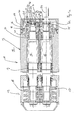
- the spindle pump 10 has a housing 11 which has a pump section 12, a bearing section 13 and a gear section 14. These are spatially and hydraulically separated from each other. Further, the spindle pump 10 includes a driven shaft 15 and a driven shaft 16. On the driven shaft 15 is a feed screw 17 and on the driven shaft 16, a feed screw 18 is arranged, which are engaged. In the storage section 13 is a needle bearing 19 and a roller bearing 20 are provided, so that the shafts are mounted in external storage outside the pump section 12. The shaft end 22 of the driven shaft 15 extends out of the housing 11 and has there a connection 24 for a drive unit 49. On the driven shaft 15 is a gear 25. On the driven shaft, a gear 26 is arranged. The teeth of the gears 25, 26 are meshingly engaged.
- a fastening element 27 is arranged on the shaft end 23.
- the fastening element 27 has a bushing section 28 and a flange section 29.
- the outside of the bushing portion 28 is at the same time receiving surface 30 for the gear 26.
- a feather key 31 is inserted, via which a rotational engagement between the shaft 16 and fastener 27 is made.
- a hexagonal screw 33 is screwed, with which a clamping plate 34 is screwed against a seat 35 on the fastening element 27.
- the fastening element 27 is connected to the shaft end 23 in a locking manner.
- the flange portion 29 has a bore 36.
- the gear 26 has a corresponding bore 37, which can be designed as a through hole or as a hole.
- a thread (not shown) is arranged in the bore 37.
- a hexagonal screw 38 is screwed, whereby the flange portion 29 of the fastener 27 is locked to the gear 26.
- Behind the bushing portion 28 of the fastener 27 is a spacer sleeve 39, which ensures that the gear 26 can not come into contact with the mounting screws 40 of the gear portion 14 with the bearing portion 13.
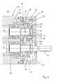
- Fig. 2 a sectional view through the gear portion 14 is shown. Visible here are the gear wheels 25, 26 in engagement.
- the fastening element 27 with its flange section 29 is shown on the gear 26.
- the clamping disk 34 is mounted in the seat 35 of the flange portion 29.
- the bore 36 in the flange portion 29 is designed as a slot 41.
- the gear portion 14 on its upper side an opening 42 which is connected to a cover 43 via hexagon bolts 44 to the gear portion 14 holding.
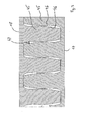
- Fig. 3 shows a sectional view through the engaged conveyor screws 17, 18.
- the conveyor screws have screw projections 45, which have flanks 46 respectively.
- the distance between the flanks 46 represents the backlash 47.
- the backlash 47 is therefore such that the fastening element 27 is rotatably mounted on the shaft end 23 and the driven shaft 16 via the feather key 31. Subsequently, the clamping disk 34 is screwed into the seat 35 via the hexagonal screw 33.
- the gear 26 is located at the time already on the receiving surface 30 of the female portion 28 of the fastener 27 and is engaged with the gear 25 of the driven shaft 15.
- the flange 29 with the slots therein 41 over the holes 37 arranged in the gear 26 and the hexagon screws 38 are screwed, with no locking connection between the flange portion 29 and gear 26 is formed. By turning the flange portion 29, it is now possible to adjust the flank clearance 47 between the feed screw 18 and the feed screw 17. If the optimum adjustment of the backlash 47 is reached, a locking connection via the hexagon screws 38 is generated.
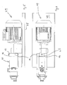
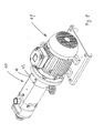
- Fig. 4 to Fig. 7 show an arrangement of the spindle pump 10 on a base plate 48.
- the spindle pump 10 is connected to a drive unit 49.
- Fig. 8 to Fig. 11 show a further embodiment in which the pump is in block construction.
- each plan views are shown on the gear portion 14 without mounted cover 43 on the opening 42.
- the gear portion 14 in this case has a planar portion 50, in which around the opening 42 around holes 51 are arranged, which have a thread (not shown), in which the hexagon screws 44 are screwed.
Landscapes
- Engineering & Computer Science (AREA)
- Mechanical Engineering (AREA)
- General Engineering & Computer Science (AREA)
- Rotary Pumps (AREA)
- Details And Applications Of Rotary Liquid Pumps (AREA)
Abstract
Description
- Die Erfindung betrifft eine Zweispindelige Schraubenspindelpumpe in einflutiger Bauweise mit einem Pumpengehäuse, das einen Pumpenabschnitt, einen Lagerabschnitt und einen Getriebeabschnitt mit einem Getrieberaum aufweist, wobei der Lagerabschnitt und der Pumpenabschnitt getrennt voneinander ausgeführt sind, mit einem Fördergehäuseteil als Bestandteil des Pumpenabschnitts, in dem zwei auf Wellen angeordnete Förderschrauben mit Flanken vorgesehen sind, wobei die Wellen im Lagerabschnitt gelagert sind (Außenlagerung) und sich in den Getriebeabschnitt erstrecken, mit auf den Wellen im Getriebeabschnitt angeordneten Zahnrädern, mittels derer die Wellen drehgekoppelt sind, mit einem auf der Welle in Wirkverbindung mit diesen angeordneten Befestigungselement zum Herstellen einer haltenden Verbindung zwischen Welle und Zahnrad, wobei das Befestigungselement und das Zahnrad korrespondierende Bohrungen aufweisen, über die zwischen dem Zahnrad und dem Befestigungselement eine haltende Verbindung über ein Arretierelement herstellbar ist.
- Die auf den Wellen angeordneten Förderschrauben sind mit einem definierten Spiel zwischen den Flanken (Flankenspiel) befestigt.
- Ein solcher Pumpenaufbau ist bekannt aus der
DE 2009014604 U1 . Diese Pumpen zeichnen sich insbesondere durch einen produktschonenden Betrieb und eine damit einhergehende Verschleißarmut aus. - Es besteht Verbesserungsbedarf dahingehend, dass der Aufwand bei der Wartung der Pumpen reduziert werden soll. Dieses tritt insbesondere dann auf, wenn die Förderschrauben oder die Gleitringdichtungen aus Verschleißgründen ausgewechselt werden und das Flankenspiel nachjustiert werden muss. Hierfür ist es gegenwärtig notwendig, dass auch der Getriebe- und Lagerabschnitt der Pumpe vom Antrieb gelöst werden müssen, um anschließend eine adäquate Einstellung des Flankenspiels der Förderschrauben vornehmen zu können.
- Aufgabe der Erfindung ist es, die vorgenannte Pumpe dahingehend zu verbessern, dass eine einfachere und weniger zeitaufwendige Wartung bzw. Nachjustierung vorgenommen werden kann.
- Gelöst wird die Aufgabe dadurch, dass am Getriebeabschnitt des Pumpengehäuses eine Öffnung vorgesehen ist, dass die Öffnung mit einer lösbaren Abdeckung versehen ist, dass die Öffnung so angeordnet ist, dass die Abdeckungen im montierten Zustand der Spindelpumpe lösbar ist, und dass der Getrieberaum zur Einstellung des Flankenspiels der Förderschrauben mit den dafür notwendigen Werkzeugen erreichbar ist.
- Durch die Vorsehung der Öffnung im Gehäuse ist es möglich, den zeitlichen Aufwand bei der Spindelnachjustierung erheblich zu reduzieren, weil es nicht mehr notwendig ist, das Getriebegehäuse zur Freilegung des Getrieberaumes zu demontieren und auch nicht notwendig ist, das Antriebsmodul zu demontieren.
- Eine weitere Lehre der Erfindung sieht vor, dass die Bohrungen im Befestigungselement so ausgeführt sind, dass das Zahnrad und das Befestigungselement (und damit die Welle) gegeneinander verdrehbar sind, so dass ein Abstand der Flanken der Förderschrauben (das Flankenspiel der Förderschrauben) einstellbar ist, dass die Bohrungen im Befestigungselement dabei als radiales Langloch vorgesehen sind, in denen das Arretierelement im eingesetzten aber nicht arretierten Zustand radial verschiebbar ist, und dass die radiale Länge des Langlochs dabei so vorgesehen ist, dass dessen Endpunkte mindestens mit den Berührungspunkten der Flanken der Förderschrauben übereinstimmen.
- Die Wartung und Einstellbarkeit der Spindelpumpe werden dabei dadurch verbessert, dass es möglich ist, das gesamte Flankenspiel der Förderschrauben durch die Bereitstellung des Langlochs einzustellen. Bisher war es hierbei notwendig, dass das Zahnrad ggf. von der Welle entfernt werden und neu in einer verdrehten Weise aufgesetzt werden musste, um das Flankenspiel adäquat einstellen zu können. Dieser Einstellaufwand wird dadurch erheblich reduziert.
- Eine weitere Lehre der Erfindung sieht vor, dass das Befestigungselement mit den Langlöchern nur an einer Welle vorgesehen ist. Dieses trägt dem Aspekt Rechnung, dass sich herausgestellt hat, dass es ausreichend ist, lediglich die eine Welle zu justieren, während die andere Welle konstant montiert ist.
- Eine weitere Lehre der Erfindung sieht vor, dass die radiale Länge der Langlöcher länger ist, als der radiale Abstand der Berührungspunkte der Flanken der Förderschrauben. Hierdurch ist es möglich, evtl. einseitigen Verschleiß der Flanken durch ein entsprechendes Verschieben über die ursprünglichen Endpunkte hinaus auszugleichen.
- Eine weitere Lehre der Erfindung sieht vor, dass zwischen Pumpenabschnitt und Lagerabschnitt eine hydraulische Trennung besteht, bevorzugt über eine Gleitringdichtung und/oder dass zwischen Lagerabschnitt und Getriebeabschnitt eine räumliche Trennung besteht. In Bezug auf die Einstellbarkeit des Flankenspiels und der Lagerung haben sich diese räumlichen Trennungen als besonders vorteilhaft erwiesen.
- Weiterhin ist es vorteilhaft, dass das Befestigungselement einen Buchsenabschnitt zum Aufschieben auf die Welle aufweist, wobei der Buchsenabschnitt bevorzugt einen Aufnahmeabschnitt für das Zahnrad aufweist, und/oder wobei die Welle und der Buchsenabschnitt eine Nut zur Aufnahme einer Passfeder zur Herstellung einer drehwirksamen Verbindung zwischen Welle und Befestigungselement aufweisen. Diese Ausführungselement stellt eine kostengünstige und besonders wartungsfreundliche Ausführungsform der Erfindung dar.
- Eine weitere vorteilhafte Ausführungsform der Erfindung ist, dass die Bohrungen des Zahnrads als Lochbohrung mit Gewindeabschnitt ausgeführt sind, und/oder dass in die Bohrungen ein Arretierelement in Form einer Schraube einsetzbar ist, über die die haltende Verbindung herstellbar ist. Weiterhin ist vorteilhaft, dass im Wellenkopf eine Bohrung vorgesehen ist, in die ein Arretierelement einbringbar ist, das das Befestigungselement gegen die Welle, bevorzugt mit einer Klemmscheibe, arretiert. Nachfolgend wird die Erfindung anhand eines Ausführungsbeispiels in Verbindung mit einer Zeichnung näher erläutert. Dabei zeigen:
- Fig. 1a
- eine Schnittansicht durch eine erfindungsgemäße Pumpendraufsicht,
- Fig. 1 b
- eine vergrößerte Ausschnittansicht zu
Fig. 1 a, - Fig. 2
- eine Schnittansicht einer erfindungsgemäßen Pumpe in Schnittansicht durch den Getriebeabschnitt,
- Fig. 3
- eine Schnittansicht durch die Förderschrauben,
- Fig. 4
- eine räumliche Ansicht einer ersten Ausführungsform einer erfindungsgemäßen Pumpe mit Antrieb,
- Fig. 5.
- eine Seitenansicht zu
Fig. 4 , - Fig. 6
- eine Draufsicht zu
Fig. 4 , - Fig. 7
- eine Draufsicht auf den Getriebeabschnitt zu
Fig. 1 in Ausführung zuFig. 4 , - Fig. 8
- eine räumliche Ansicht einer zweiten Ausführungsform,
- Fig. 9
- eine Seitenansicht zu
Fig. 8 , - Fig. 10
- eine Draufsicht zu
Fig. 8 und - Fig. 11
- eine Draufsicht des Getriebeabschnitts zu
Fig. 1 in Ausführung zuFig. 8 . -
Fig. 1a undFig. 1b zeigen eine Schnittansicht in Draufsicht einer erfindungsgemäßen Spindelpumpe 10. Die Spindelpumpe 10 weist ein Gehäuse 11 auf, das einen Pumpenabschnitt 12, einen Lagerabschnitt 13 und einen Getriebeabschnitt 14 aufweist. Diese sind räumlich und hydraulisch von einander getrennt. Des Weiteren umfasst die Spindelpumpe 10 eine angetriebene Welle 15 und eine getriebene Welle 16. An der angetriebenen Welle 15 ist eine Förderschraube 17 und an der getriebenen Welle 16 ist eine Förderschraube 18 angeordnet, die sich im Eingriff befinden. Im Lagerabschnitt 13 ist ein Nadellager 19 und ein Rollenlager 20 vorgesehen, so dass die Wellen in Außenlagerung außerhalb des Pumpabschnitts 12 gelagert sind. Im Getrieberaum 21 befinden sich die Wellenenden 22, 23. Das Wellenende 22 der angetriebenen Welle 15 erstreckt sich aus dem Gehäuse 11 heraus und weist dort einen Anschluss 24 für eine Antriebseinheit 49 auf. Auf der angetriebenen Welle 15 befindet sich ein Zahnrad 25. Auf der getriebenen Welle ist ein Zahnrad 26 angeordnet. Die Zähne der Zahnräder 25, 26 befinden sich kämmend im Eingriff. - Auf der getriebenen Welle 16 ist auf dem Wellenende 23 ein Befestigungselement 27 angeordnet. Das Befestigungselement 27 weist einen Buchsenabschnitt 28 und einen Flanschabschnitt 29 auf. Die Außenseite des Buchsenabschnitts 28 ist gleichzeitig Aufnahmefläche 30 für das Zahnrad 26. In eine Nut (nicht dargestellt) in dem Wellenende 23 und im Befestigungselement 27 ist eine Passfeder 31 eingesetzt, über die eine Drehwirkverbindung zwischen Welle 16 und Befestigungselement 27 hergestellt wird. In einer Bohrung (nicht dargestellt) in der Stirnfläche 32 des Wellenendes 23 ist eine Sechskantschraube 33 eingeschraubt, mit der eine Spannscheibe 34 gegen einen Sitz 35 am Befestigungselement 27 festgeschraubt wird. Dadurch wird das Befestigungselement 27 mit dem Wellenende 23 arretierend verbunden. Der Flanschabschnitt 29 weist eine Bohrung 36 auf. Das Zahnrad 26 weist eine korrespondierende Bohrung 37 auf, die als Durchgangsbohrung oder als Lochbohrung ausgeführt sein kann. In der Bohrung 37 ist ein Gewinde (nicht dargestellt) angeordnet. In dieses Gewinde wird eine Sechskantschraube 38 eingeschraubt, wodurch der Flanschabschnitt 29 des Befestigungselements 27 mit dem Zahnrad 26 arretiert wird. Hinter dem Buchsenabschnitt 28 des Befestigungselements 27 befindet sich eine Abstandsbuchse 39, mit der gewährleistet wird, dass das Zahnrad 26 nicht mit den Befestigungsschrauben 40 des Getriebeabschnitts 14 mit dem Lagerabschnitt 13 in Berührung kommen kann.
- In
Fig. 2 ist eine Schnittansicht durch den Getriebeabschnitt 14 dargestellt. Erkennbar sind dabei die sich im Eingriff befindlichen Zahnräder 25, 26. Auf dem Zahnrad 26 ist das Befestigungselement 27 mit seinem Flanschabschnitt 29 dargestellt. Über die Sechskantschraube 33 ist die Spannscheibe 34 in den Sitz 35 des Flanschabschnitts 29 montiert. Die Bohrung 36 im Flanschabschnitt 29 ist dabei als Langloch 41 ausgeführt. Des Weiteren weist der Getriebeabschnitt 14 an seiner Oberseite eine Öffnung 42 auf, die mit einem Deckel 43 über Sechskantschrauben 44 mit dem Getriebeabschnitt 14 haltend verbunden ist. -
Fig. 3 zeigt eine Schnittansicht durch die im Eingriff befindlichen Förderschrauben 17, 18. Die Förderschrauben weisen Schraubenvorsprünge 45 auf, die jeweils Flanken 46 haben. Der Abstand zwischen den Flanken 46 stellt das Flankenspiel 47 dar. Durch Drehen der getriebenen Welle 16 und damit der Förderschraube 18, während die angetriebene Welle 15 und damit die Förderschraube 17 stillstehen, verändert sich das Flankenspiel 47 derart, dass es auf der einen Seite größer und auf der anderen Seite des Schraubenvorsprungs 45 kleiner wird. Die optimale Anordnung der Förderschrauben 17, 18 erfolgt dergestalt, dass die Flankenspiele zu beiden Seiten der Schraubenvorsprünge 45 gleichgroß sind. - Das Einstelen des Flankenspiels 47 erfolgt daher dergestalt, dass das Befestigungselement 27 auf dem Wellenende 23 bzw. der getriebenen Welle 16 über die Passfeder 31 drehfest angeordnet ist. Anschließend wird die Spannscheibe 34 in den Sitz 35 über die Sechskantschraube 33 festgeschraubt. Das Zahnrad 26 befindet sich zu dem Zeitpunkt bereits auf der Aufnahmefläche 30 des Buchsenabschnitts 28 des Befestigungselements 27 und ist im Eingriff mit dem Zahnrad 25 der angetriebenen Welle 15. Zur Einstellung des Flankenspiels wird jetzt der Flanschabschnitt 29 mit den darin befindlichen Langlöchern 41 über den Bohrungen 37 im Zahnrad 26 angeordnet und die Sechskantschrauben 38 werden eingeschraubt, wobei noch keine arretierende Verbindung zwischen Flanschabschnitt 29 und Zahnrad 26 entsteht. Durch Drehen des Flanschabschnitts 29 besteht jetzt die Möglichkeit das Flankenspiel 47 zwischen der Förderschraube 18 und der Förderschraube 17 einzustellen. Ist die optimale Einstellung des Flankenspiels 47 erreicht, wird eine arretierende Verbindung über die Sechskantschrauben 38 erzeugt.
-
Fig. 4 bis Fig. 7 zeigen eine Anordnung der Spindelpumpe 10 auf einer Grundplatte 48. Die Spindelpumpe 10 ist dabei mit einer Antriebseinheit 49 verbunden.Fig. 8 bis Fig. 11 zeigen eine weitere Ausführungsform, bei der die Pumpe in Blockbauweise vorliegt. InFig. 7 undFig. 11 sind jeweils Draufsichten auf dem Getriebeabschnitt 14 ohne montiertem Deckel 43 auf der Öffnung 42 dargestellt. Der Getriebeabschnitt 14 weist dabei einen planen Abschnitt 50 auf, in dem um die Öffnung 42 herum Bohrungen 51 angeordnet sind, die ein Gewinde (nicht dargestellt) aufweisen, in das die Sechskantschrauben 44 eingeschraubt werden. - Wird es aufgrund von Wartungsarbeiten beispielsweise an der Gleitringdichtung, Verschleiß oder aufgrund eines Wechsels der Förderschrauben 17, 18 notwendig, das Flankenspiel 47 neu einzustellen, ist es möglich, durch Entfernen der Sechskantschrauben 44 und der Abnahme des Deckels 43 durch die Öffnung 42 in den Getrieberaum 21 mit einem Werkzeug (nicht dargestellt) einzugreifen. Es ist beispielsweise möglich, die Sechskantschrauben 38 zu lösen, um eine Verdrehung der getriebenen Welle 16 gegen über dem Zahnrad 26 zu erreichen und damit das Flankenspiel 47 neu einzustellen. Nach Einstellung des Flankenspiels werden dann die Sechskantschrauben 38 wieder festgezogen und der Deckel 43 mit den Sechskantschrauben 44 wieder auf den planen Abschnitt 50 durch Einbringen der Sechskantschrauben 44 in die Bohrung 51 betriebsbereit gemacht.
- Es ist damit nicht mehr notwendig, die Antriebseinheiten 49 und/oder den Getriebeabschnitt 14 des Gehäuses 11 zu lösen. Weiterhin ist es durch die Langlöcher 41 nicht mehr notwendig, das Zahnrad 26 von der Welle 16 aufwendig zu entnehmen, um dann durch entsprechendes Drehen des Zahnrads 26 um einen Kreisabschnitt, bis die nächste Bohrung 36 fluchtet, und anschließendes Wiederaufstecken des Zahnrades 26 auf die Welle 16 das Flankenspiel 47 aufwendig einzustellen.
-
- 10
- Spindelpumpe
- 11
- Gehäuse
- 12
- Pumpenabschnitt
- 13
- Lagerabschnitt
- 14
- Getriebeabschnitt
- 15
- angetriebene Welle
- 16
- getriebene Welle
- 17
- Förderschraube
- 18
- Förderschraube
- 19
- Nadellager
- 20
- Rollenlager
- 21
- Getrieberaum
- 22
- Wellenende
- 23
- Wellenende
- 24
- Anschluss
- 25
- Zahnrad
- 26
- Zahnrad
- 27
- Befestigungselement
- 28
- Buchsenabschnitt
- 29
- Flanschabschnitt
- 30
- Aufnahmefläche
- 31
- Passfeder
- 32
- Stirnfläche
- 33
- Sechskantschraube
- 34
- Spannscheibe
- 35
- Sitz
- 36
- Bohrung
- 37
- Bohrung
- 38
- Sechskantschraube
- 39
- Abstandsbuchse
- 40
- Befestigungsschraube
- 41
- Langloch
- 42
- Öffnung
- 43
- Deckel
- 44
- Sechskantschraube
- 45
- Schraubenvorsprung
- 46
- Flanke
- 47
- Flankenspiel
- 48
- Grundplatte
- 49
- Antriebseinheit
- 50
- planer Abschnitt
- 51
- Bohrung
Claims (8)
- Zweispindelige Schraubenspindelpumpe in einflutiger Bauweise mit einem Pumpengehäuse, das einen Pumpenabschnitt, einen Lagerabschnitt und einen Getriebeabschnitt mit einem Getrieberaum aufweist, wobei der Lagerabschnitt und der Pumpenabschnitt getrennt voneinander ausgeführt sind,- mit einem Fördergehäuseteil als Bestandteil des Pumpenabschnitts, in dem zwei auf Wellen angeordnete Förderschrauben mit Flanken vorgesehen sind, wobei die Wellen im Lagerabschnitt gelagert sind (Außenlagerung) und sich in den Getriebeabschnitt erstrecken,- mit auf den Wellen im Getriebeabschnitt angeordneten Zahnrädern, mittels derer die Wellen drehgekoppelt sind,- mit einem auf der Welle in Wirkverbindung mit diesen angeordneten Befestigungselement zum Herstellen einer haltenden Verbindung zwischen Welle und Zahnrad, wobei das Befestigungselement und das Zahnrad korrespondierende Bohrungen aufweisen, über die zwischen dem Zahnrad und dem Befestigungselement eine haltende Verbindung über ein Arretierelement herstellbar ist, dadurch gekennzeichnet, dass die Bohrungen im Befestigungselement so ausgeführt sind, dass das Zahnrad und das Befestigungselement (und damit die Welle) gegeneinander verdrehbar sind, so dass ein Abstand der Flanken, der Förderschrauben (das Flankenspiel der Förderschrauben) einstellbar ist, dass am Getriebeabschnitt des Pumpengehäuses eine Öffnung vorgesehen ist, dass die Öffnung mit einer lösbaren Abdeckung versehen, dass die Öffnung so angeordnet ist, dass die Abdeckung im montierten Zustand der Spindelpumpe lösbar ist, und dass der Getrieberaum zur Einstellung des Flankenspiels der Förderschrauben mit dem dafür notwendigen Werkzeug erreichbar ist.
- Spindelpumpe nach Anspruch 1, dadurch gekennzeichnet, dass die Bohrungen im Befestigungselement dabei als radiales Langloch vorgesehen sind, in denen das Arretierelement im eingesetzten aber nicht arretierten Zustand radial verschiebbar ist, und dass die radiale Länge des Langlochs dabei so vorgesehen ist, dass dessen Endpunkte mindestens mit den Berührungspunkten der Flanken der Förderschrauben übereinstimmen.
- Spindelpumpe nach Anspruch 2, dadurch gekennzeichnet, dass das Befestigungselement mit den Langlöchern nur an einer Welle vorgesehen ist.
- Spindelpumpe nach Anspruch 2 oder 3, dadurch gekennzeichnet, dass die radiale Länge der Langlöcher länger ist, als der radiale Abstand der Berührungspunkte der Flanken der Förderschrauben.
- Pumpe nach einem der Ansprüche 1 bis 4, dadurch gekennzeichnet, dass zwischen Pumpabschnitt und Lagerabschnitt eine hydraulische Trennung besteht, bevorzug über eine Gleitringdichtung, und/oder dass zwischen Lagerabschnitt und Getriebeabschnitt eine räumliche Trennung besteht.
- Pumpe nach einem der Ansprüche 1 bis 5, dadurch gekennzeichnet, dass das Befestigungselement einen Buchsenabschnitt zum Aufschieben auf die Welle aufweist, wobei der Buchsenabschnitt bevorzugt einen Aufnahmeabschnitt für das Zahnrad aufweist, und/oder wobei die Welle und der Buchsenabschnitt eine Nut zur Aufnahme einer Passfeder zur Herstellung einer Drehwirkverbindung zwischen Welle und Befestigungselement aufweisen.
- Pumpe nach einem der Ansprüche 1 bis 6, dadurch gekennzeichnet, dass die Bohrungen des Zahnrads als Lochbohrungen mit Gewindeabschnitt ausgeführt sind, und/oder dass in die Bohrung ein Arretierelement in Form einer Schraube einsetzbar ist, über die die haltende Verbindung herstellbar ist.
- Pumpe nach einem der Ansprüche 1 bis 7, dadurch gekennzeichnet, dass im Wellenkopf eine Bohrung vorgesehen ist, in die ein Arretierelement einbringbar ist, dass das Befestigungselement gegen die Welle arretiert.
Applications Claiming Priority (1)
| Application Number | Priority Date | Filing Date | Title |
|---|---|---|---|
| DE102012001700A DE102012001700B4 (de) | 2012-01-31 | 2012-01-31 | Zweispindelige Schraubenspindelpumpe in einflutiger Bauweise |
Publications (4)
| Publication Number | Publication Date |
|---|---|
| EP2634366A2 true EP2634366A2 (de) | 2013-09-04 |
| EP2634366A3 EP2634366A3 (de) | 2015-11-18 |
| EP2634366C0 EP2634366C0 (de) | 2024-02-28 |
| EP2634366B1 EP2634366B1 (de) | 2024-02-28 |
Family
ID=47681604
Family Applications (1)
| Application Number | Title | Priority Date | Filing Date |
|---|---|---|---|
| EP13000395.7A Active EP2634366B1 (de) | 2012-01-31 | 2013-01-28 | Zweispindelige Schraubenspindelpumpe in einflutiger Bauweise mit Zahnrädern, mittels derer die Spindeln drehgekoppelt sind. |
Country Status (4)
| Country | Link |
|---|---|
| US (1) | US9624925B2 (de) |
| EP (1) | EP2634366B1 (de) |
| DE (1) | DE102012001700B4 (de) |
| ES (1) | ES2974944T3 (de) |
Cited By (2)
| Publication number | Priority date | Publication date | Assignee | Title |
|---|---|---|---|---|
| CN111082629A (zh) * | 2020-01-10 | 2020-04-28 | 刘发明 | 一种单线环绕的无刷马达 |
| EP4095384A1 (de) * | 2021-05-27 | 2022-11-30 | Jung & Co. Gerätebau GmbH | Schraubenspindelpumpe in einflutiger bauweise |
Families Citing this family (14)
| Publication number | Priority date | Publication date | Assignee | Title |
|---|---|---|---|---|
| DE202014010877U1 (de) | 2014-02-24 | 2017-01-02 | Jung & Co. Gerätebau GmbH | Zweispindelige Schraubenspindelpumpe in einflutiger Bauweise |
| DE102014002396A1 (de) | 2014-02-24 | 2015-08-27 | Jung & Co. Gerätebau GmbH | Zweispindelige Schraubenspindelpumpe in einflutiger Bauweise |
| DE102014011658A1 (de) | 2014-08-11 | 2016-02-11 | Jung & Co. Gerätebau GmbH | Schraubenspindelpumpe mit Dampfsperre |
| USD749138S1 (en) | 2014-12-19 | 2016-02-09 | Q-Pumps S.A. de C.V. | Twin screw pump |
| DE102017007832A1 (de) | 2017-08-22 | 2019-02-28 | Pumpenfabrik Wangen Gmbh | Verfahren zur Herstellung eines Drehkolbens für eine Schraubenspindelpumpe |
| USD896845S1 (en) * | 2018-06-12 | 2020-09-22 | Alfa Laval Corporate Ab | Twin screw pump |
| USD896846S1 (en) * | 2018-06-12 | 2020-09-22 | Alfa Laval Corporate Ab | Twin screw pump |
| JP6766850B2 (ja) * | 2018-08-24 | 2020-10-14 | 株式会社タツノ | 容積型ポンプ |
| DE102020103384B4 (de) | 2020-02-11 | 2025-11-13 | Gardner Denver Deutschland Gmbh | Schraubenverdichter mit einseitig gelagerten Rotoren |
| DE102020124392A1 (de) * | 2020-09-18 | 2022-03-24 | Itt Bornemann Gmbh | Abstandseinstellung für doppelschneckenpumpen |
| USD973722S1 (en) * | 2021-01-19 | 2022-12-27 | Alfa Laval Corporate Ab | Rotary positive displacement pump |
| USD976962S1 (en) * | 2021-01-19 | 2023-01-31 | Alfa Laval Corporate Ab | Rotary positive-displacement pump |
| DE202024100727U1 (de) | 2024-02-15 | 2024-02-29 | FRISTAM Pumpen Schaumburg GmbH | Verdrängerpumpe mit Synchrongetriebe |
| DE102024104230A1 (de) | 2024-02-15 | 2025-08-21 | FRISTAM Pumpen Schaumburg GmbH | Verdrängerpumpe mit Synchrongetriebe |
Citations (1)
| Publication number | Priority date | Publication date | Assignee | Title |
|---|---|---|---|---|
| DE202009014604U1 (de) | 2009-10-29 | 2010-01-28 | Jung & Co. Gerätebau GmbH | Schraubenspindelpumpe mit Kupplung |
Family Cites Families (15)
| Publication number | Priority date | Publication date | Assignee | Title |
|---|---|---|---|---|
| US1805875A (en) * | 1917-02-13 | 1931-05-19 | Jeffrey Mfg Co | Rotary engine |
| US2287716A (en) * | 1941-04-22 | 1942-06-23 | Joseph E Whitfield | Fluid device |
| US2641937A (en) * | 1949-07-15 | 1953-06-16 | Crown Cork & Seal Co | Adjustable torsion shaft in flying shears |
| US2683994A (en) * | 1951-05-17 | 1954-07-20 | Read Standard Corp | Adjusting device |
| US3037396A (en) * | 1959-05-11 | 1962-06-05 | Merrill David Martin | Backlash preventing gears for coupled driven and drive shafts |
| US3057665A (en) * | 1960-06-24 | 1962-10-09 | Warren Pumps Inc | Pump |
| DE2001000A1 (de) * | 1970-01-10 | 1971-07-15 | Allweiler Ag | Einstelleinrichtung an Schraubenspindelpumpen |
| CH613258A5 (de) * | 1975-09-24 | 1979-09-14 | Suter Fa Alois | |
| SE454202B (sv) * | 1982-06-07 | 1988-04-11 | Atlas Copco Ab | Kompressordrivarrangemang for justering av driftkarakteristika |
| US6027322A (en) * | 1997-10-29 | 2000-02-22 | Coltec Industries Inc | Method and apparatus for adjusting the rotors of a rotary screw compressor |
| DE59806719D1 (de) * | 1998-04-11 | 2003-01-30 | Bornemann J H Gmbh | Spaltringdichtung |
| EP1061260A1 (de) * | 1999-05-18 | 2000-12-20 | Sterling Fluid Systems (Germany) GmbH | Verdrängermaschine für kompressible Medien |
| DE10257859C5 (de) * | 2002-12-11 | 2012-03-15 | Joh. Heinr. Bornemann Gmbh | Schraubenspindelpumpe |
| WO2006087038A1 (fr) * | 2005-02-16 | 2006-08-24 | Ateliers Busch Sa | Machine rotative volumétriques avec rotors à profils asymétriques |
| GB2432631A (en) * | 2005-11-24 | 2007-05-30 | Timothy John Sweatman | Meshing gear type pump controlled by phase adjustment |
-
2012
- 2012-01-31 DE DE102012001700A patent/DE102012001700B4/de active Active
-
2013
- 2013-01-28 ES ES13000395T patent/ES2974944T3/es active Active
- 2013-01-28 EP EP13000395.7A patent/EP2634366B1/de active Active
- 2013-01-30 US US13/754,650 patent/US9624925B2/en active Active
Patent Citations (1)
| Publication number | Priority date | Publication date | Assignee | Title |
|---|---|---|---|---|
| DE202009014604U1 (de) | 2009-10-29 | 2010-01-28 | Jung & Co. Gerätebau GmbH | Schraubenspindelpumpe mit Kupplung |
Cited By (2)
| Publication number | Priority date | Publication date | Assignee | Title |
|---|---|---|---|---|
| CN111082629A (zh) * | 2020-01-10 | 2020-04-28 | 刘发明 | 一种单线环绕的无刷马达 |
| EP4095384A1 (de) * | 2021-05-27 | 2022-11-30 | Jung & Co. Gerätebau GmbH | Schraubenspindelpumpe in einflutiger bauweise |
Also Published As
| Publication number | Publication date |
|---|---|
| EP2634366A3 (de) | 2015-11-18 |
| DE102012001700B4 (de) | 2013-09-12 |
| EP2634366C0 (de) | 2024-02-28 |
| US20130251581A1 (en) | 2013-09-26 |
| US9624925B2 (en) | 2017-04-18 |
| EP2634366B1 (de) | 2024-02-28 |
| DE102012001700A1 (de) | 2013-08-01 |
| ES2974944T3 (es) | 2024-07-02 |
Similar Documents
| Publication | Publication Date | Title |
|---|---|---|
| DE102012001700B4 (de) | Zweispindelige Schraubenspindelpumpe in einflutiger Bauweise | |
| DE102012005949B4 (de) | Zweispindelige Schraubenspindelpumpe in zweiflutiger Bauweise | |
| DE102010017464B4 (de) | Planetenträger eines Planetengetriebes sowie Planetengetriebe | |
| DE102015200741A1 (de) | Getriebe und Verfahren zur Einstellung des Verdrehspiels dieses Getriebes | |
| DE202010016197U1 (de) | Spielfrei laufendes Zahnrad | |
| EP3472492B1 (de) | Planetengetriebe | |
| EP2726756B1 (de) | Verstellantrieb für ein fahrzeug, insbesondere heckklappenantrieb | |
| DE1952265A1 (de) | Stirnmesserkopf,insbesondere fuer Verzahnungsmaschine | |
| DE10054798B4 (de) | Elektrisch angetriebene Vorrichtung zur Drehwinkelverstellung einer Welle gegenüber ihrem Antrieb | |
| DE102012002361B4 (de) | Matrizenscheibe für Matrizenbuchsen einer Rundläufertablettenpresse sowie Rotor mit einer solchen Matrizenscheibe | |
| EP3234389B1 (de) | Kupplungselement und kupplungsanordnung zur axialen drehmomentübertragung, und lamellenanordnung für solche | |
| DE202012000894U1 (de) | Zweispindelige Schraubenspindelpumpe in einflutiger Bauweise | |
| DE102012001699B4 (de) | Zweispindelige Schraubenspindelpumpe in einflutiger Bauweise | |
| DE102020133211A1 (de) | Verfahren zur Montage eines Fräsrads einer Schlitzwandfräse | |
| DE2649130B2 (de) | Zahnradpumpe | |
| DE202012000893U1 (de) | Zweispindelige Schraubenspindelpumpe in einflutiger Bauweise | |
| DE202013100690U1 (de) | Schneidwerkzeugmaschine | |
| DE102010010209B4 (de) | Matrizenscheibe | |
| DE3130229C2 (de) | Mehrschneidenwerkzeug | |
| EP2210720B1 (de) | Reibschlüssige rotationswerkzeugbefestigungsvorrichtung | |
| DE202012003018U1 (de) | Zweispindelige Schraubenspindelpumpe in zweiflutiger Bauweise | |
| DE19512976A1 (de) | Antriebsaggregat, insbesondere Drehwerksantrieb, mit einem Planetengetriebe und einem Abtriebselement | |
| EP1857680B1 (de) | Rotorbaugruppe | |
| DE102004058177A1 (de) | Zahnrad | |
| DE202004014344U1 (de) | Vorrichtung zum Arretieren eines Schwungrades |
Legal Events
| Date | Code | Title | Description |
|---|---|---|---|
| PUAI | Public reference made under article 153(3) epc to a published international application that has entered the european phase |
Free format text: ORIGINAL CODE: 0009012 |
|
| AK | Designated contracting states |
Kind code of ref document: A2 Designated state(s): AL AT BE BG CH CY CZ DE DK EE ES FI FR GB GR HR HU IE IS IT LI LT LU LV MC MK MT NL NO PL PT RO RS SE SI SK SM TR |
|
| AX | Request for extension of the european patent |
Extension state: BA ME |
|
| PUAL | Search report despatched |
Free format text: ORIGINAL CODE: 0009013 |
|
| AK | Designated contracting states |
Kind code of ref document: A3 Designated state(s): AL AT BE BG CH CY CZ DE DK EE ES FI FR GB GR HR HU IE IS IT LI LT LU LV MC MK MT NL NO PL PT RO RS SE SI SK SM TR |
|
| AX | Request for extension of the european patent |
Extension state: BA ME |
|
| RIC1 | Information provided on ipc code assigned before grant |
Ipc: F04C 2/16 20060101ALI20151013BHEP Ipc: F04C 15/00 20060101ALI20151013BHEP Ipc: F01C 21/10 20060101ALI20151013BHEP Ipc: F01C 17/02 20060101AFI20151013BHEP Ipc: F04C 2/00 20060101ALI20151013BHEP |
|
| 17P | Request for examination filed |
Effective date: 20160509 |
|
| RBV | Designated contracting states (corrected) |
Designated state(s): AL AT BE BG CH CY CZ DE DK EE ES FI FR GB GR HR HU IE IS IT LI LT LU LV MC MK MT NL NO PL PT RO RS SE SI SK SM TR |
|
| STAA | Information on the status of an ep patent application or granted ep patent |
Free format text: STATUS: EXAMINATION IS IN PROGRESS |
|
| 17Q | First examination report despatched |
Effective date: 20171110 |
|
| TPAC | Observations filed by third parties |
Free format text: ORIGINAL CODE: EPIDOSNTIPA |
|
| TPAC | Observations filed by third parties |
Free format text: ORIGINAL CODE: EPIDOSNTIPA |
|
| GRAP | Despatch of communication of intention to grant a patent |
Free format text: ORIGINAL CODE: EPIDOSNIGR1 |
|
| STAA | Information on the status of an ep patent application or granted ep patent |
Free format text: STATUS: GRANT OF PATENT IS INTENDED |
|
| INTG | Intention to grant announced |
Effective date: 20231004 |
|
| GRAS | Grant fee paid |
Free format text: ORIGINAL CODE: EPIDOSNIGR3 |
|
| GRAA | (expected) grant |
Free format text: ORIGINAL CODE: 0009210 |
|
| STAA | Information on the status of an ep patent application or granted ep patent |
Free format text: STATUS: THE PATENT HAS BEEN GRANTED |
|
| AK | Designated contracting states |
Kind code of ref document: B1 Designated state(s): AL AT BE BG CH CY CZ DE DK EE ES FI FR GB GR HR HU IE IS IT LI LT LU LV MC MK MT NL NO PL PT RO RS SE SI SK SM TR |
|
| REG | Reference to a national code |
Ref country code: GB Ref legal event code: FG4D Free format text: NOT ENGLISH |
|
| REG | Reference to a national code |
Ref country code: CH Ref legal event code: EP |
|
| REG | Reference to a national code |
Ref country code: DE Ref legal event code: R096 Ref document number: 502013016496 Country of ref document: DE |
|
| REG | Reference to a national code |
Ref country code: IE Ref legal event code: FG4D Free format text: LANGUAGE OF EP DOCUMENT: GERMAN |
|
| U01 | Request for unitary effect filed |
Effective date: 20240319 |
|
| U07 | Unitary effect registered |
Designated state(s): AT BE BG DE DK EE FI FR IT LT LU LV MT NL PT SE SI Effective date: 20240326 |
|
| PG25 | Lapsed in a contracting state [announced via postgrant information from national office to epo] |
Ref country code: IS Free format text: LAPSE BECAUSE OF FAILURE TO SUBMIT A TRANSLATION OF THE DESCRIPTION OR TO PAY THE FEE WITHIN THE PRESCRIBED TIME-LIMIT Effective date: 20240628 |
|
| REG | Reference to a national code |
Ref country code: ES Ref legal event code: FG2A Ref document number: 2974944 Country of ref document: ES Kind code of ref document: T3 Effective date: 20240702 |
|
| PG25 | Lapsed in a contracting state [announced via postgrant information from national office to epo] |
Ref country code: GR Free format text: LAPSE BECAUSE OF FAILURE TO SUBMIT A TRANSLATION OF THE DESCRIPTION OR TO PAY THE FEE WITHIN THE PRESCRIBED TIME-LIMIT Effective date: 20240529 |
|
| PG25 | Lapsed in a contracting state [announced via postgrant information from national office to epo] |
Ref country code: RS Free format text: LAPSE BECAUSE OF FAILURE TO SUBMIT A TRANSLATION OF THE DESCRIPTION OR TO PAY THE FEE WITHIN THE PRESCRIBED TIME-LIMIT Effective date: 20240528 Ref country code: HR Free format text: LAPSE BECAUSE OF FAILURE TO SUBMIT A TRANSLATION OF THE DESCRIPTION OR TO PAY THE FEE WITHIN THE PRESCRIBED TIME-LIMIT Effective date: 20240228 |
|
| PG25 | Lapsed in a contracting state [announced via postgrant information from national office to epo] |
Ref country code: RS Free format text: LAPSE BECAUSE OF FAILURE TO SUBMIT A TRANSLATION OF THE DESCRIPTION OR TO PAY THE FEE WITHIN THE PRESCRIBED TIME-LIMIT Effective date: 20240528 Ref country code: NO Free format text: LAPSE BECAUSE OF FAILURE TO SUBMIT A TRANSLATION OF THE DESCRIPTION OR TO PAY THE FEE WITHIN THE PRESCRIBED TIME-LIMIT Effective date: 20240528 Ref country code: IS Free format text: LAPSE BECAUSE OF FAILURE TO SUBMIT A TRANSLATION OF THE DESCRIPTION OR TO PAY THE FEE WITHIN THE PRESCRIBED TIME-LIMIT Effective date: 20240628 Ref country code: HR Free format text: LAPSE BECAUSE OF FAILURE TO SUBMIT A TRANSLATION OF THE DESCRIPTION OR TO PAY THE FEE WITHIN THE PRESCRIBED TIME-LIMIT Effective date: 20240228 Ref country code: GR Free format text: LAPSE BECAUSE OF FAILURE TO SUBMIT A TRANSLATION OF THE DESCRIPTION OR TO PAY THE FEE WITHIN THE PRESCRIBED TIME-LIMIT Effective date: 20240529 |
|
| PG25 | Lapsed in a contracting state [announced via postgrant information from national office to epo] |
Ref country code: PL Free format text: LAPSE BECAUSE OF FAILURE TO SUBMIT A TRANSLATION OF THE DESCRIPTION OR TO PAY THE FEE WITHIN THE PRESCRIBED TIME-LIMIT Effective date: 20240228 |
|
| PG25 | Lapsed in a contracting state [announced via postgrant information from national office to epo] |
Ref country code: PL Free format text: LAPSE BECAUSE OF FAILURE TO SUBMIT A TRANSLATION OF THE DESCRIPTION OR TO PAY THE FEE WITHIN THE PRESCRIBED TIME-LIMIT Effective date: 20240228 |
|
| PG25 | Lapsed in a contracting state [announced via postgrant information from national office to epo] |
Ref country code: SM Free format text: LAPSE BECAUSE OF FAILURE TO SUBMIT A TRANSLATION OF THE DESCRIPTION OR TO PAY THE FEE WITHIN THE PRESCRIBED TIME-LIMIT Effective date: 20240228 |
|
| PG25 | Lapsed in a contracting state [announced via postgrant information from national office to epo] |
Ref country code: CZ Free format text: LAPSE BECAUSE OF FAILURE TO SUBMIT A TRANSLATION OF THE DESCRIPTION OR TO PAY THE FEE WITHIN THE PRESCRIBED TIME-LIMIT Effective date: 20240228 |
|
| PG25 | Lapsed in a contracting state [announced via postgrant information from national office to epo] |
Ref country code: SK Free format text: LAPSE BECAUSE OF FAILURE TO SUBMIT A TRANSLATION OF THE DESCRIPTION OR TO PAY THE FEE WITHIN THE PRESCRIBED TIME-LIMIT Effective date: 20240228 |
|
| PG25 | Lapsed in a contracting state [announced via postgrant information from national office to epo] |
Ref country code: SM Free format text: LAPSE BECAUSE OF FAILURE TO SUBMIT A TRANSLATION OF THE DESCRIPTION OR TO PAY THE FEE WITHIN THE PRESCRIBED TIME-LIMIT Effective date: 20240228 Ref country code: SK Free format text: LAPSE BECAUSE OF FAILURE TO SUBMIT A TRANSLATION OF THE DESCRIPTION OR TO PAY THE FEE WITHIN THE PRESCRIBED TIME-LIMIT Effective date: 20240228 Ref country code: RO Free format text: LAPSE BECAUSE OF FAILURE TO SUBMIT A TRANSLATION OF THE DESCRIPTION OR TO PAY THE FEE WITHIN THE PRESCRIBED TIME-LIMIT Effective date: 20240228 Ref country code: CZ Free format text: LAPSE BECAUSE OF FAILURE TO SUBMIT A TRANSLATION OF THE DESCRIPTION OR TO PAY THE FEE WITHIN THE PRESCRIBED TIME-LIMIT Effective date: 20240228 |
|
| REG | Reference to a national code |
Ref country code: DE Ref legal event code: R097 Ref document number: 502013016496 Country of ref document: DE |
|
| PLBE | No opposition filed within time limit |
Free format text: ORIGINAL CODE: 0009261 |
|
| STAA | Information on the status of an ep patent application or granted ep patent |
Free format text: STATUS: NO OPPOSITION FILED WITHIN TIME LIMIT |
|
| U20 | Renewal fee for the european patent with unitary effect paid |
Year of fee payment: 13 Effective date: 20241220 |
|
| 26N | No opposition filed |
Effective date: 20241129 |
|
| REG | Reference to a national code |
Ref country code: CH Ref legal event code: PL |
|
| PG25 | Lapsed in a contracting state [announced via postgrant information from national office to epo] |
Ref country code: MC Free format text: LAPSE BECAUSE OF FAILURE TO SUBMIT A TRANSLATION OF THE DESCRIPTION OR TO PAY THE FEE WITHIN THE PRESCRIBED TIME-LIMIT Effective date: 20240228 |
|
| GBPC | Gb: european patent ceased through non-payment of renewal fee |
Effective date: 20250128 |
|
| PG25 | Lapsed in a contracting state [announced via postgrant information from national office to epo] |
Ref country code: GB Free format text: LAPSE BECAUSE OF NON-PAYMENT OF DUE FEES Effective date: 20250128 |
|
| PG25 | Lapsed in a contracting state [announced via postgrant information from national office to epo] |
Ref country code: CH Free format text: LAPSE BECAUSE OF NON-PAYMENT OF DUE FEES Effective date: 20250131 |
|
| PG25 | Lapsed in a contracting state [announced via postgrant information from national office to epo] |
Ref country code: IE Free format text: LAPSE BECAUSE OF NON-PAYMENT OF DUE FEES Effective date: 20250128 |
|
| U20 | Renewal fee for the european patent with unitary effect paid |
Year of fee payment: 14 Effective date: 20260116 |
|
| PGFP | Annual fee paid to national office [announced via postgrant information from national office to epo] |
Ref country code: ES Payment date: 20260227 Year of fee payment: 14 |