EP2633989A2 - Schrottverdichter und vorrichtung zu seiner herstellung - Google Patents
Schrottverdichter und vorrichtung zu seiner herstellung Download PDFInfo
- Publication number
- EP2633989A2 EP2633989A2 EP11836539.4A EP11836539A EP2633989A2 EP 2633989 A2 EP2633989 A2 EP 2633989A2 EP 11836539 A EP11836539 A EP 11836539A EP 2633989 A2 EP2633989 A2 EP 2633989A2
- Authority
- EP
- European Patent Office
- Prior art keywords
- scrap
- compressed
- housing
- core
- outlet
- Prior art date
- Legal status (The legal status is an assumption and is not a legal conclusion. Google has not performed a legal analysis and makes no representation as to the accuracy of the status listed.)
- Withdrawn
Links
- 238000004519 manufacturing process Methods 0.000 title claims abstract description 17
- 230000003247 decreasing effect Effects 0.000 claims description 2
- 238000002844 melting Methods 0.000 abstract description 5
- 230000008018 melting Effects 0.000 abstract description 5
- 230000000694 effects Effects 0.000 abstract description 4
- 239000000126 substance Substances 0.000 abstract 1
- 238000010276 construction Methods 0.000 description 5
- XEEYBQQBJWHFJM-UHFFFAOYSA-N Iron Chemical compound [Fe] XEEYBQQBJWHFJM-UHFFFAOYSA-N 0.000 description 2
- 229910000831 Steel Inorganic materials 0.000 description 2
- 239000000463 material Substances 0.000 description 2
- 239000010959 steel Substances 0.000 description 2
- 239000002699 waste material Substances 0.000 description 2
- 230000015572 biosynthetic process Effects 0.000 description 1
- 239000006227 byproduct Substances 0.000 description 1
- 230000007423 decrease Effects 0.000 description 1
- 239000010791 domestic waste Substances 0.000 description 1
- 238000010891 electric arc Methods 0.000 description 1
- 238000005265 energy consumption Methods 0.000 description 1
- 229910052742 iron Inorganic materials 0.000 description 1
- 239000000047 product Substances 0.000 description 1
- 239000003923 scrap metal Substances 0.000 description 1
Images




Classifications
-
- B—PERFORMING OPERATIONS; TRANSPORTING
- B30—PRESSES
- B30B—PRESSES IN GENERAL
- B30B9/00—Presses specially adapted for particular purposes
- B30B9/32—Presses specially adapted for particular purposes for consolidating scrap metal or for compacting used cars
- B30B9/328—Presses specially adapted for particular purposes for consolidating scrap metal or for compacting used cars for making furnace charges
-
- B—PERFORMING OPERATIONS; TRANSPORTING
- B30—PRESSES
- B30B—PRESSES IN GENERAL
- B30B13/00—Methods of pressing not special to the use of presses of any one of the preceding main groups
-
- B—PERFORMING OPERATIONS; TRANSPORTING
- B30—PRESSES
- B30B—PRESSES IN GENERAL
- B30B15/00—Details of, or accessories for, presses; Auxiliary measures in connection with pressing
- B30B15/02—Dies; Inserts therefor; Mounting thereof; Moulds
-
- B—PERFORMING OPERATIONS; TRANSPORTING
- B30—PRESSES
- B30B—PRESSES IN GENERAL
- B30B9/00—Presses specially adapted for particular purposes
- B30B9/32—Presses specially adapted for particular purposes for consolidating scrap metal or for compacting used cars
- B30B9/327—Presses specially adapted for particular purposes for consolidating scrap metal or for compacting used cars for briquetting scrap metal
Definitions
- the present invention relates generally to a compressed scrap and an apparatus for manufacturing the same and, more particularly, to a compressed scrap having improved melting behavior and being capable of preventing the massaging of the weight of the compressed scrap, and a manufacturing apparatus therefor.
- scrap i.e., scrap metal
- Electric furnaces are charged with scrap and melt the scrap into molten steel by means of an electric arc generated by electrode rods.
- the scrap is collected from domestic waste, construction waste, by-products of various manufacturing industries, and service life-expired waste materials.
- an object of the present invention is to provide a compressed scrap capable of being smoothly melted in electric furnaces and preventing the massaging of the weight of the compressed scrap when scrap suppliers deliver the compressed scrap to electric furnace plants.
- Another object of the present invention is to provide an apparatus for manufacturing the compressed scrap.
- the present invention provides a compressed scrap including a hexahedral compressed body, wherein a through-hole passes through opposite faces thereof.
- the hexahedral compressed body may be of a rectangular or regular hexahedron in shape.
- the through-hole may consist of a plurality of through-holes perpendicular to each other, wherein each of the through-holes passes through the center of the compressed scrap.
- the present invention provides an apparatus for manufacturing a compressed scrap, including:
- the core may be disposed under the housing such that the core vertically reciprocates through an opening formed through a lower surface of the housing.
- the core may be attached to a front surface of the support door.
- the core may be of a cylindrical or conical shape.
- the core may have a sectional area decreasing in size in the direction of a distal end thereof.
- a pair of pressing plates may be disposed to face each other on the outside of the outlet of the housing to press and fix the compressed scrap discharged from the housing on opposite sides thereof.
- a pair of cross-cores may be disposed on the outside of opposite housing walls such that the cross-cores approach each other perpendicular to and come into close contact with opposite surfaces of a circumference of the core that has been inserted into the space.
- the compressing plate may be configured to advance toward the compressed scrap and discharge it out from the housing.
- the housing may be configured to tilt to the outlet such that the compressed scrap is discharged out from the housing through the outlet.
- the present invention facilitates the smooth heat transfer throughout the compressed scrap along the through-hole, having the effect of improving the melting behavior of the compressed scrap.
- the present invention facilitates the easy observation of the inside of the compressed scrap through the through-hole, having the effect of preventing the massaging of the weight of the compressed scrap, which is carried out by deliberately adding heavy weights that are other than scrap into the scrap when manufacturing the compressed scrap.
- the present invention can manufacture the compressed scrap using the manufacturing apparatus.
- a compressed scrap S includes a rectangular (or regular) hexahedral body which is provided with a through-hole h.
- the through-hole h passes through the center of the compressed scrap S.
- the through-hole h formed in the compressed scrap S reduces the weight of the compressed scrap and thus facilitates the handling and delivery of the compressed scrap.
- the through-hole enables heat to be transferred directly throughout the inside of the compressed scrap to improve the melting behavior of the compressed scrap.
- heat from a heat source is not gradually transferred from the outer surface of the compressed scrap toward the center thereof, but is transferred directly to the inside of the compressed scrap, so that the compressed scrap is melted more efficiently and quickly.
- the compressed scrap S may be provided with a plurality of through-holes h1 and h2 as shown in Fig. 2 .
- the plurality of through-holes h1 and h2 all pass through opposite faces of the compressed scrap S via the center thereof such that they are perpendicular to each other.
- the apparatus includes a housing 10 which defines a space for compressing scrap, a support door 20 which is fixedly insertable into the space through an outlet (right opening in the drawing) of the housing 10 when compressing scrap and is removable from the space through the outlet to open the outlet when completing the compressing of the scrap, a compressing plate 30 which is insertable into the space through an inlet (left opening in the drawing) of the housing 10 to compress the scrap, which has already been supplied into the space, against the support door to form the compressed scraps, and a core 40 which is inserted into the space before the compressing of the scrap using the compressing plate 30, to form a through-hole h in the compressed scrap S when compressing the scrap.
- the housing 10 has a hollow rectangular parallelepiped, opposite sides of which are open, wherein one side (the left side in the drawing) is used both as an inlet for scrap and an entrance for the compressing plate 30, and another side (the right side in the drawing) is used both as an outlet for a compressed scrap S and an entrance for the support door 20.
- the housing 10 may be separately provided on its upper surface with an opening door which is used as an inlet for scrap.
- the support door 20, the compressing plate 30, and the core 40 are mounted to ends of cylinder rods of hydraulic cylinders, respectively, so as to advance towards and retract from the inside of the housing 10.
- the support door 20 and the compressing plate 30 are composed of a thick steel plate strong enough to withstand a compressed load of the scrap, and the surfaces thereof with which the scrap comes into direct contact are thermally treated to improve the surface hardness.
- the core 40 has a cylindrical shape which is intended not to interfere with or to minimize an interruption of compressing movement of the scrap.
- the compressing operation of the scrap is carried out as follows.
- the support door 20 moves forward in the space of the housing 10 and is fixedly held at a certain position.
- the core 40 is raised up completely into the space of the housing 10 through an entrance 11 formed on a lower surface of the housing 10, and is held in that state.
- scrap is introduced into the space of the housing through an inlet that is opposite the outlet or an entrance that is separately formed on the upper surface of the housing 10, and the compressing plate 30 is moved forward in the space of the housing 10.
- the through-hole h is formed in the hexahedral compressed scrap S while passing through the center thereof , by the core 40.
- the compressing plate 30 advances further to discharge the compressed scrap S out of the outlet.
- the housing 10 may be configured to tilt such that the level of the outlet becomes lower than that of the inlet in order to allow the compressed scrap S to be discharged out by its own weight (since this configuration may be simply established by fixing one side of the housing 10 and inclining the other side of the housing 10 using an actuator, ordinary persons skilled in the art can implement this configuration with ease by selectively combining conventional constructions if needed, even though it is not shown in a separate drawing).
- the finished compressed scrap may be conveyed using a vehicle or a table which is prepared in front of the outlet of the housing.
- the compressed scrap is loaded on the table, which is conveyed using a crane.
- the through-hole h formed in the compressed scrap is used as a lifting eye.
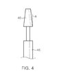
- the core 40 may have a frustoconical shape with a certain inclined angle ( ⁇ ). That is, the core has a diameter that decreases from a lower end thereof to an upper end thereof.
- the core 40 may be disposed on a front surface of the support door 20 as shown in Fig. 5 .
- the core 40 moves in and out through the outlet of the housing 10, together with the support door 20, so that the housing 10 need not have a separate entrance 11 as shown in Fig. 3 on its lower side.
- a separate hydraulic cylinder for actuating the core 40 is not also required.
- the support door 20 and the core 40 are first inserted into the space of the housing 10 and are held at a predefined position, then scrap is introduced into the space of the housing 10, and the compressing plate 30 is moved forward to compress the scrap into a compressed scrap S.
- the direction of the through-hole h formed is not significant because the compressed scrap is of a hexahedral shape. That is, the compressed scrap S is of the same shape as those of the compressed scrap manufactured by the construction shown in Fig. 3 .
- the core 40 preferably has a diameter that reduces from the rear portion to the front portion.
- Such a shape may be a conical shape, for example.
- An apparatus shown in Fig. 7 is a construction that prepares the case where in the embodiment of Fig. 5 , even though the core 40 is formed like a conical shape, the core 40 is not removed from the compressed scrap S, so the compressed scrap S is discharged in a state where it is combined with the core 40.
- the embodiment of Fig. 7 is characterized in that it further includes a fixing unit for the compressed scrap as compared to the embodiment of Fig. 5 .
- the fixing unit includes a pair of pressing plates 50 which press against the opposite surfaces of the compressed scrap S combined with the core 40, and a pair of hydraulic cylinders 55 which reciprocates the pressing plates 50, respectively.
- the pressing plate 50 may be provided on its leading surface with a plurality of pointed protrusions to increase the fixing force for the compressed scrap S.
- the pressing plates of the fixing unit are disposed on opposite sides of the housing such that they face each other, and are operated at the same time.
- the opposite pressing plates are then moved forward each other to firmly grip the compressed scrap S. Subsequently, the support door 20 and the core 40 are further moved back, thereby separating the compressed scrap S and the core 40 from each other.
- the pressing plates 50 are moved back to their original positions, and as described before, the compressed scrap S is delivered.
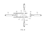
- An apparatus of Fig. 8 is a construction that manufactures the compressed scrap S shown in Fig. 2 in which through-holes h1 and h2 that intersect with each other are formed.
- Fig. 8 is a plan view of the apparatus (however, a housing is shown in section) which includes a core 40 which is disposed under the housing 10 such that it moves up and down as shown in Fig. 3 .
- the core 40 accesses to the inside of the housing 10 through an entrance 11 formed on a lower surface of the housing 10.
- Cross-cores 60 in pair are disposed at a position lying on the same line with the core 40, on the outside of opposite housing walls.
- the cross-cores 60 are also mounted to the cylinder rods of the hydraulic cylinders 65, respectively.
- the cross-cores 60 may access to the inside of the housing 10 through an entrance 12 formed on the opposite housing walls.
- leading surfaces (facing each other) of the cross-cores 60 are concavely formed to have the same curvature as a circumference of the core 40 such that they surround and come into close contact with opposite surfaces of the circumference of the core 40 which is mounted below the housing.
- the cross-cores 60 perpendicularly meet the core 40 to form a cross line, thereby forming intersecting through-holes h1 and h2 in the compressed scrap S.
Landscapes
- Engineering & Computer Science (AREA)
- Mechanical Engineering (AREA)
- Processing Of Solid Wastes (AREA)
- Manufacture And Refinement Of Metals (AREA)
Applications Claiming Priority (2)
| Application Number | Priority Date | Filing Date | Title |
|---|---|---|---|
| KR1020100105295A KR101205148B1 (ko) | 2010-10-27 | 2010-10-27 | 스크랩 압축체 제조장치 |
| PCT/KR2011/006424 WO2012057447A2 (ko) | 2010-10-27 | 2011-08-30 | 스크랩 압축체와 그 제조장치 |
Publications (1)
| Publication Number | Publication Date |
|---|---|
| EP2633989A2 true EP2633989A2 (de) | 2013-09-04 |
Family
ID=45994498
Family Applications (1)
| Application Number | Title | Priority Date | Filing Date |
|---|---|---|---|
| EP11836539.4A Withdrawn EP2633989A2 (de) | 2010-10-27 | 2011-08-30 | Schrottverdichter und vorrichtung zu seiner herstellung |
Country Status (6)
| Country | Link |
|---|---|
| US (1) | US9375891B2 (de) |
| EP (1) | EP2633989A2 (de) |
| JP (1) | JP5710773B2 (de) |
| KR (1) | KR101205148B1 (de) |
| CN (1) | CN103328196B (de) |
| WO (1) | WO2012057447A2 (de) |
Families Citing this family (4)
| Publication number | Priority date | Publication date | Assignee | Title |
|---|---|---|---|---|
| KR101327213B1 (ko) * | 2012-06-11 | 2013-11-11 | 이태호 | 천공된 금속 스크랩 압축물 배출 장치 |
| KR101924785B1 (ko) | 2017-07-19 | 2018-12-04 | 이유기 | 도우넛형 분철 압축기 |
| KR101844194B1 (ko) * | 2017-11-13 | 2018-03-30 | 주식회사 금강테크놀러지 | 폐분말 압착성형장치 |
| KR102521071B1 (ko) * | 2021-04-08 | 2023-04-12 | 장일산업(주) | 압축 제강원료의 제조시스템 |
Family Cites Families (15)
| Publication number | Priority date | Publication date | Assignee | Title |
|---|---|---|---|---|
| US3386374A (en) * | 1966-09-02 | 1968-06-04 | Tezuka Kunitoshi | Scrap-metal compressor |
| GB1217878A (en) * | 1967-10-03 | 1970-12-31 | Giovanni Busi | Horizontal press |
| JPS503028B1 (de) * | 1969-07-03 | 1975-01-30 | ||
| JPS5229966B2 (de) | 1973-05-14 | 1977-08-05 | ||
| JPS5353167A (en) * | 1976-10-26 | 1978-05-15 | Topii Jitsugiyou Kk | Press formation method and apparatus for metallic scrap |
| US4103610A (en) * | 1976-11-22 | 1978-08-01 | Luciano Vezzani | Metal scrap compacting press |
| JPS5398170A (en) * | 1977-02-08 | 1978-08-28 | Topii Jitsugiyou Kk | Presssforming method and apparatus for metal scraps |
| JPH0636076B2 (ja) * | 1985-04-12 | 1994-05-11 | 株式会社日立製作所 | 放射性廃棄物の造粒装置 |
| JPH02165899A (ja) | 1988-12-19 | 1990-06-26 | Fuji Car Mfg Co Ltd | スクラップ圧縮装置 |
| JP3308694B2 (ja) | 1994-01-28 | 2002-07-29 | 本田技研工業株式会社 | スクラッププレス装置 |
| KR100235540B1 (ko) * | 1997-04-21 | 1999-12-15 | 백충기 | 고철 압착장치 |
| JP2005014072A (ja) * | 2003-06-27 | 2005-01-20 | Mori Tekko Kk | 研磨スラッジブリケット製造装置 |
| KR20090009739U (ko) * | 2008-03-24 | 2009-09-29 | 황영규 | 고철 압축기 |
| CN201325190Y (zh) * | 2008-12-23 | 2009-10-14 | 孙立国 | 以油缸进行推料、压料、压块成型的金属屑压块机 |
| KR101134916B1 (ko) * | 2011-01-28 | 2012-04-17 | 이태호 | 금속 스크랩 압축물 및 그 제조장치와 제조 방법 |
-
2010
- 2010-10-27 KR KR1020100105295A patent/KR101205148B1/ko active Active
-
2011
- 2011-08-30 CN CN201180055131.4A patent/CN103328196B/zh active Active
- 2011-08-30 JP JP2013536492A patent/JP5710773B2/ja active Active
- 2011-08-30 EP EP11836539.4A patent/EP2633989A2/de not_active Withdrawn
- 2011-08-30 WO PCT/KR2011/006424 patent/WO2012057447A2/ko not_active Ceased
- 2011-08-30 US US13/882,031 patent/US9375891B2/en active Active
Non-Patent Citations (1)
| Title |
|---|
| See references of WO2012057447A2 * |
Also Published As
| Publication number | Publication date |
|---|---|
| US20130220147A1 (en) | 2013-08-29 |
| US9375891B2 (en) | 2016-06-28 |
| JP2013545614A (ja) | 2013-12-26 |
| KR101205148B1 (ko) | 2012-11-26 |
| KR20120043973A (ko) | 2012-05-07 |
| CN103328196B (zh) | 2015-11-25 |
| WO2012057447A2 (ko) | 2012-05-03 |
| CN103328196A (zh) | 2013-09-25 |
| WO2012057447A3 (ko) | 2012-06-21 |
| JP5710773B2 (ja) | 2015-04-30 |
Similar Documents
| Publication | Publication Date | Title |
|---|---|---|
| US9375891B2 (en) | Scrap compactor and apparatus for manufacturing same | |
| US20120266724A1 (en) | Apparatus and method for manufacturing compressed lump of metal scrap | |
| US5669957A (en) | Dross compression apparatus and method utilizing ribs on collector and head | |
| US8661971B2 (en) | Method of manufacturing compressed lump of metal scrap | |
| CN105689685B (zh) | 一种破碎机颚板的液态模锻模具和方法 | |
| JP2006104528A (ja) | 製鋼ダスト固形化物およびその製造方法 | |
| KR101176886B1 (ko) | 철스크랩 압축장치 | |
| CN223082832U (zh) | 一种高效废混凝土构件静压破碎装备 | |
| CN211471473U (zh) | 一种金属冶炼用具有原料筛选功能的平炉 | |
| CN112878873A (zh) | 一种具有偏航结构的人防工程安全防护门及其制造工艺 | |
| KR101246382B1 (ko) | 스크랩 압축체 제조방법 | |
| Barkov et al. | Device for one-and two-sided molding of refractory metal powders into electric-arc melting electrode workpieces | |
| CN210522576U (zh) | 一种玻璃破碎机 | |
| RU2324595C2 (ru) | Устройство для формования длинномерных заготовок из порошковых материалов | |
| KR102922395B1 (ko) | 알루미늄 압출 성형장치 | |
| RU2283718C2 (ru) | Четырехбойковое ковочное устройство | |
| RU2289634C1 (ru) | Способ брикетирования шихтовых материалов | |
| CN213593159U (zh) | 一种砧板加工装置 | |
| US6718810B1 (en) | Method and apparatus for bringing elongated metallic scrap into a more compact form | |
| RU2415730C1 (ru) | Устройство для обработки металлов давлением | |
| CN111448058B (zh) | 废金属压缩机 | |
| CN210104640U (zh) | 一种专用清理工具 | |
| KR100682373B1 (ko) | 신장된 금속 스크랩을 보다 압축된 형태로 만드는 방법 및장치 | |
| KR101573213B1 (ko) | 철 스크랩 압축장치 | |
| KR20220032152A (ko) | 금속 스크랩 압축물 및 그 제조장치와 제조 방법 |
Legal Events
| Date | Code | Title | Description |
|---|---|---|---|
| PUAI | Public reference made under article 153(3) epc to a published international application that has entered the european phase |
Free format text: ORIGINAL CODE: 0009012 |
|
| 17P | Request for examination filed |
Effective date: 20130527 |
|
| AK | Designated contracting states |
Kind code of ref document: A2 Designated state(s): AL AT BE BG CH CY CZ DE DK EE ES FI FR GB GR HR HU IE IS IT LI LT LU LV MC MK MT NL NO PL PT RO RS SE SI SK SM TR |
|
| RIN1 | Information on inventor provided before grant (corrected) |
Inventor name: KI, JOON-SEONG |
|
| DAX | Request for extension of the european patent (deleted) | ||
| STAA | Information on the status of an ep patent application or granted ep patent |
Free format text: STATUS: THE APPLICATION HAS BEEN WITHDRAWN |
|
| 18W | Application withdrawn |
Effective date: 20170216 |