EP2633231B1 - Doppelreflektorsystem für lineare lampenbeleuchtungskörper - Google Patents
Doppelreflektorsystem für lineare lampenbeleuchtungskörper Download PDFInfo
- Publication number
- EP2633231B1 EP2633231B1 EP11833680.9A EP11833680A EP2633231B1 EP 2633231 B1 EP2633231 B1 EP 2633231B1 EP 11833680 A EP11833680 A EP 11833680A EP 2633231 B1 EP2633231 B1 EP 2633231B1
- Authority
- EP
- European Patent Office
- Prior art keywords
- primary
- reflector
- cylindrical reflector
- illuminator system
- light source
- Prior art date
- Legal status (The legal status is an assumption and is not a legal conclusion. Google has not performed a legal analysis and makes no representation as to the accuracy of the status listed.)
- Active
Links
Images






Classifications
-
- F—MECHANICAL ENGINEERING; LIGHTING; HEATING; WEAPONS; BLASTING
- F21—LIGHTING
- F21V—FUNCTIONAL FEATURES OR DETAILS OF LIGHTING DEVICES OR SYSTEMS THEREOF; STRUCTURAL COMBINATIONS OF LIGHTING DEVICES WITH OTHER ARTICLES, NOT OTHERWISE PROVIDED FOR
- F21V7/00—Reflectors for light sources
- F21V7/04—Optical design
- F21V7/06—Optical design with parabolic curvature
-
- F—MECHANICAL ENGINEERING; LIGHTING; HEATING; WEAPONS; BLASTING
- F21—LIGHTING
- F21V—FUNCTIONAL FEATURES OR DETAILS OF LIGHTING DEVICES OR SYSTEMS THEREOF; STRUCTURAL COMBINATIONS OF LIGHTING DEVICES WITH OTHER ARTICLES, NOT OTHERWISE PROVIDED FOR
- F21V7/00—Reflectors for light sources
- F21V7/0025—Combination of two or more reflectors for a single light source
- F21V7/0033—Combination of two or more reflectors for a single light source with successive reflections from one reflector to the next or following
-
- F—MECHANICAL ENGINEERING; LIGHTING; HEATING; WEAPONS; BLASTING
- F21—LIGHTING
- F21V—FUNCTIONAL FEATURES OR DETAILS OF LIGHTING DEVICES OR SYSTEMS THEREOF; STRUCTURAL COMBINATIONS OF LIGHTING DEVICES WITH OTHER ARTICLES, NOT OTHERWISE PROVIDED FOR
- F21V7/00—Reflectors for light sources
- F21V7/005—Reflectors for light sources with an elongated shape to cooperate with linear light sources
-
- F—MECHANICAL ENGINEERING; LIGHTING; HEATING; WEAPONS; BLASTING
- F21—LIGHTING
- F21V—FUNCTIONAL FEATURES OR DETAILS OF LIGHTING DEVICES OR SYSTEMS THEREOF; STRUCTURAL COMBINATIONS OF LIGHTING DEVICES WITH OTHER ARTICLES, NOT OTHERWISE PROVIDED FOR
- F21V7/00—Reflectors for light sources
- F21V7/04—Optical design
-
- F—MECHANICAL ENGINEERING; LIGHTING; HEATING; WEAPONS; BLASTING
- F21—LIGHTING
- F21V—FUNCTIONAL FEATURES OR DETAILS OF LIGHTING DEVICES OR SYSTEMS THEREOF; STRUCTURAL COMBINATIONS OF LIGHTING DEVICES WITH OTHER ARTICLES, NOT OTHERWISE PROVIDED FOR
- F21V7/00—Reflectors for light sources
- F21V7/22—Reflectors for light sources characterised by materials, surface treatments or coatings, e.g. dichroic reflectors
- F21V7/24—Reflectors for light sources characterised by materials, surface treatments or coatings, e.g. dichroic reflectors characterised by the material
-
- G—PHYSICS
- G03—PHOTOGRAPHY; CINEMATOGRAPHY; ANALOGOUS TECHNIQUES USING WAVES OTHER THAN OPTICAL WAVES; ELECTROGRAPHY; HOLOGRAPHY
- G03B—APPARATUS OR ARRANGEMENTS FOR TAKING PHOTOGRAPHS OR FOR PROJECTING OR VIEWING THEM; APPARATUS OR ARRANGEMENTS EMPLOYING ANALOGOUS TECHNIQUES USING WAVES OTHER THAN OPTICAL WAVES; ACCESSORIES THEREFOR
- G03B15/00—Special procedures for taking photographs; Apparatus therefor
- G03B15/02—Illuminating scene
- G03B15/03—Combinations of cameras with lighting apparatus; Flash units
-
- F—MECHANICAL ENGINEERING; LIGHTING; HEATING; WEAPONS; BLASTING
- F21—LIGHTING
- F21Y—INDEXING SCHEME ASSOCIATED WITH SUBCLASSES F21K, F21L, F21S and F21V, RELATING TO THE FORM OR THE KIND OF THE LIGHT SOURCES OR OF THE COLOUR OF THE LIGHT EMITTED
- F21Y2103/00—Elongate light sources, e.g. fluorescent tubes
-
- G—PHYSICS
- G03—PHOTOGRAPHY; CINEMATOGRAPHY; ANALOGOUS TECHNIQUES USING WAVES OTHER THAN OPTICAL WAVES; ELECTROGRAPHY; HOLOGRAPHY
- G03B—APPARATUS OR ARRANGEMENTS FOR TAKING PHOTOGRAPHS OR FOR PROJECTING OR VIEWING THEM; APPARATUS OR ARRANGEMENTS EMPLOYING ANALOGOUS TECHNIQUES USING WAVES OTHER THAN OPTICAL WAVES; ACCESSORIES THEREFOR
- G03B2215/00—Special procedures for taking photographs; Apparatus therefor
- G03B2215/05—Combinations of cameras with electronic flash units
- G03B2215/0582—Reflectors
Definitions
- This invention generally relates to illuminator systems, and more specifically a linear lamp illuminator system with a dual reflector system.
- Flashlamps are often used as illumination sources for machine vision or surveillance cameras. However, the flashlamp emits light in all directions, so a collimating optical system must be used to concentrate the light onto the target of interest. Cylindrical parabolic or paraboloid reflectors are often used to collimate the light from linear flashlamps, sometimes in conjunction with a fresnel refractive lens. Unfortunately these standard methods have a number of drawbacks.
- Cylindrical reflectors can only collimate the light in one plane and have a very wide beam in a plane orthogonal thereto, so most of the light generated by the lamp is wasted. Adding a cylindrical fresnel lens helps, but the lens must have a long focal length and large aperture which makes it heavy and expensive. Refractive elements can also separate the colours of the light due to dispersion, which is often undesirable in applications involving optical sensors.
- Paraboloid reflectors may capture most of the light, but in order to function well the illumination source must fit entirely within the paraboloid. For long flashlamps, this imposes a large diameter for the reflector, making the reflector large and expensive. Examples of this configuration are disclosed in U.S. Patent Nos. 5,037,191 and 5,235,470 , which generally describe paraboloid reflectors for use with a linear light source. Further, some configurations of paraboloid reflectors such as the ones found in U.S. Patent Nos. 4,210,954 and 3,254,342 may produce a doughnut beam pattern which is often undesirable for imaging applications.
- U.S. Patent No. 3,938,162 describes an antenna system for single or plural beams providing continuously variable beamwidth selectively in one or both of two orthogonal senses.
- the system includes two parabolic cylindrical reflectors, which are positioned with the focal axes thereof orthogonally.
- a point of multibeam feed is mounted adjacent the main reflector on the focal axis of the sub-reflector in the Airy disc of the system. Simultaneous operation of telescoping sections of the two reflectors provides bidirectional zooming of the beam.
- U.S. Patent No. 4,208,661 describes an antenna system with two parabolic cylindrical reflectors with a point feed source located on the focal axis of one of the reflectors, wherein the directrix of the cylindrical wave front obtained by exposure of the first reflector coincides with the focal line of the second reflector, and the focal line of the first reflector is not parallel to the symmetry plane of the second reflector.
- embodiments of the present invention comprise an illuminator system comprising:
- the primary and secondary generally cylindrical reflectors may be parabolic.
- the secondary focal axis may lie at a distance from the primary vertex, and in some cases may be at a distance equal to the primary focal length from the primary vertex.
- the secondary focal length will be greater than or equal to half of the emission length of the linear light source.
- Some exemplary useful light sources are flash lamps, continuous wave cylindrical linear light sources, tungsten halogen lamps, sodium lamps, metal halide lamps, and fluorescent lamps.
- the light sources may operate as a strobe light.
- Some embodiments of the invention will include additional mirror segments located parallel to the primary generally cylindrical reflector and oriented with respect to said primary generally cylindrical reflector to reflect stray light back through said primary focal axis. Further, these mirror segments may be positioned such that light passing through said primary focal axis and reflecting from said primary generally cylindrical reflector does not reflect from said at least one mirror segment.
- the first and second planes in which the emitted light is collimated are mutually orthogonal.
- the position and orientation of the primary and secondary generally cylindrical reflectors with respect to one another may be adjustable.
- the primary generally cylindrical reflector is able to translate and rotate relative to said secondary generally cylindrical reflector in a plane perpendicular to said secondary focal axis.
- some embodiments of the invention will include a primary generally cylindrical reflector comprising a parabolic portion and a portion which wraps around the light source.
- the portion which wraps around the linear light source may be circular in shape, and the linear light source may be disposed at the centre of the circle.
- FIGs 1a and 1b show respectively a top and side view sketch of the dual reflector system 60, absent supporting structures, to illustrate the basic concept.
- the dual reflector system includes a primary generally cylindrical mirror or reflector 68 with a linear illumination source, e.g. a cylindrical flash lamp 74 aligned along the length of the focal axis (at 74 in Figure 1b ) of mirror 68.
- a secondary generally cylindrical mirror or reflector 70 is oriented relative to the primary mirror 68 such that light emitted from the linear light source is reflected from the primary and secondary mirrors 68, 70 and is thereby collimated in two planes, forming a collimated beam.
- the primary and secondary reflectors 68, 70 have primary and secondary focal axes and primary and secondary vertices 122, 120, respectively. Further, the distance between each focal axis and its respective vertex is called the focal length.
- the secondary focal axis of the secondary mirror 70 F 2 preferably falls on or behind the vertex 122 of the primary mirror 68. In the embodiment of the invention shown in Figures 1a and 1b , the focal axis of the secondary mirror 70 falls on the vertex 122 of the primary mirror 68.
- Linear light source 74 has an overall length L1 and an emission length L2.
- Figure 2 shows a perspective view of one embodiment of the invention including supporting structure and the assembled dual reflector system 60 focusing optics for producing the optical beam.
- the primary parabolic mirror/reflector 68 is mounted to a cylindrical mounting bracket 66 which in turn is mounted to a mounting bracket 64.
- Mounting bracket 64 is mounted on a base 62.
- the mounting bracket 66 may include inserts between the bracket and the mirror 68 that form the mirror 68 in the shape of a parabola.
- the secondary parabolic reflector/mirror 70 is mounted to a mirror mount 72 which in turn is mounted to base 62.
- Figure 14 shows a side view of one embodiment of the invention in which the primary generally cylindrical reflector 68 comprises a flexible sheet of reflective material. This sheet may be mounted to a base or other structure with inserts with the desired form.
- the reflector 68 is formed in the shape of a parabola by the inserts 142 mounted to a mounting bracket 64.
- the primary generally cylindrical reflector 68 is milled from reflective material and does not require supporting structure to maintain its shape.
- the secondary generally cylindrical reflector 70 may also be built in the described fashions.
- Figure 3 is a top view of the focusing optics of the dual reflector of Figures 1a, 1b .
- Figure 4 is a side view of the focusing optics of the dual reflector of Figures 1a, 1b .
- Figure 5 is a section along the line 5-5 of Figure 3 .
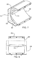
- Figure 7 is a perspective view showing the primary reflector 68, reflector mount 66 and mounting bracket 64.
- Figure 6 is a side view showing the primary reflector 68, reflector mount 66, and mounting bracket 64 of Figure 7.
- Figure 8 is a view taken along arrow 8 of Figure 6 .
- the two generally cylindrical reflectors 68 and 70 are used to collimate the light from the linear light source 74 into a narrow beam that, for instance, may match the field-of-view of a camera.
- the primary reflector 68 collimates the light in a first plane and the secondary reflector 70 collimates the light in a second plane.
- the second plane is orthogonal to the first plane.
- the primary and secondary reflectors 68, 70 are oriented such that as much as possible of the light which is not reflected by the first and second reflectors 68, 70 is preferably already collimated in the desired direction upon emission from the linear lamp 74.
- the focal length F 2 of the secondary mirror 70 is preferably equal to, or greater than, half the linear light source emission length L 2 .
- the focal length F 2 of secondary mirror 70 is made large enough so the secondary mirror 70 location accommodates the physical length L 1 of the linear light source 74 i.e. it is equal to or greater than half the physical length L 1 of the linear light source 74.
- the focal lengths ( F 1 ) of the primary mirror 68 and the secondary mirror 70 ( F 2 ) respectively are selected to achieve the desired illumination beam widths in the vertical and horizontal directions respectively given the diameter of the arc and the length of the arc.
- a preferable shape of the generally cylindrical primary reflector 68 is parabolic as shown in Figure 1a
- other shapes may provide some advantageous features.
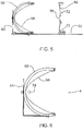
- the embodiment of a primary reflector 110 shown in Figures 8a and 8b is a primary reflector of the dual reflector system 60 wherein a portion 112 of the reflector is parabolic to collimate light, and another cylindrical portion 114 wraps around the linear illumination source 74 to capture more emitted light.
- the cylindrical mirror 110 also has the effect of altering the intensity of the output beam light distribution in the vertical plane such that the intensity increases nearer the source throughout the aperture A2.
- the shape of the vertical intensity profile of the output beam is adjusted by the cylindrical mirror angular extent aof cylindrical portion 114, which determines the proportion of directly emitted to reflected light.
- the cylindrical portion 114 that wraps around the linear illumination source 74 is circular in shape, and the linear illumination source 74 lies at the centre of the circle.
- the advantages of this feature are: increased light collection efficiency, approximately 50% reduction in the illuminator volume and the ability to improve illumination uniformity when illuminating surfaces tilted at high angles to the illuminator.
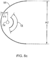
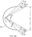
- FIGS 8c and 8d show two other configurations which capture stray light not initially directed to the primary reflector 68; these include one or more mirror segments 80 located parallel to the primary reflector 68 which reflect stray light back through the mirror focal axis. As shown in Figure 8d , the mirror segments 80 may be located such that they are not in the path of light which has passed through the primary focal axis and reflected from the primary reflector 68.
- the primary mirror 68 nor the secondary mirror 70 has to be strictly cylindrical.
- the primary and secondary mirror vertices may be curved to increase the amount of light collected in the orthogonal plane. Adding curvature may be used to decrease the size of the mirrors e.g. the primary mirror could be curved so that the secondary mirror can be shorter and likewise by adding a curvature to the secondary mirror.
- the primary mirror 68 does not need to be a pure parabolic cylinder if there is a cylindrical mirror replacing one half of the mirror.
- this phrase covers pure cylindrical in addition to these other configurations.
- the linear light source 74 may comprise many different sources of light.
- the linear light source 74 may comprise a flash lamp, a continuous wave cylindrical linear light source, a tungsten halogen lamp, a sodium lamp, a metal halide lamp, and a fluorescent lamp.
- the linear light source 74 may be a strobe light or provide continuous illumination.
- the primary focal axis may be disposed between the primary generally cylindrical reflector 68 and a plane 136 defined by two straight edges 132, 134 on the primary generally cylindrical reflector 68, as shown in Figure 13 .
- the primary and secondary generally cylindrical reflectors 68, 70 in an adjustable configuration.
- the position and orientation of either one or both of the primary and secondary generally cylindrical reflectors 68, 70 may be adjustable.
- the primary generally cylindrical reflector 68 may be able to translate and rotate on a plane perpendicular to the focal axis of the secondary generally cylindrical reflector 70.
- the position of linear light source 74 preferably remains on the focal axis of the primary mirror 68 as the primary mirror 68 position and orientation are adjusted.
- a simple geometric analysis can provide insight into what determines the average output beamwidth of the illuminator as a function of the parabola and linear light source characteristics. It should be noted that the analysis presented herein applies a simplified geometrical ray tracing and any design should include realistic models of the linear light source and mirror using more complex models and ray trace simulations.
- Figure 9 shows the cross-section geometry of the primary parabolic mirror 68 and the cross-section of the linear light source 74.
- the Figure 9 only shows one-half of the parabolic mirror 68 for simplicity.
- the y axis location of the lamp is 0.5".
- Figure 9 shows, as a circle, the internal bore of the lamp, the area that generates light.
- the lamp has an internal bore diameter of 2R.
- the active length of the lamp arc is 1 inch (but is not restricted to this length), not shown in Figure 9 .
- ⁇ Average ⁇ 0 ⁇ max ⁇ ⁇ d ⁇ ⁇ max
- Table 1 illustrates the results of the ray trace analysis for the cases of two illuminators with linear light source bore radii of 0.08 and 0.12 inches, and a total aperture width of 5 inches.
- the focal length is varied from 0.5 to 2 inches.
- the maximum angle ⁇ max is shown as an indication of the amount of light collected by the parabolic reflector where amount collected is proportional to the value of ⁇ max .
- the average angular beamwidth and the normalized peak intensity of the beam are also given.
- the central beam peak intensity is arbitrarily normalized to the smallest linear light source radius and focal length case for illustration.
- Figure 10 shows a plan view diagram of the illuminator with the primary mirror 68 and linear light source 74 located at the primary mirror 68 focal point F 1 .
- the secondary mirror 70 is positioned such that its focal plane is parallel to the primary mirror axis and a distance S from the primary mirror 68 focal point F 1 .
- the diagram is similar to Figure 9 except that the light source is a linear source rather than an isotropic cylindrical source.
- the secondary mirror 70 collects direct light from along the length of the linear light source 74 and the light reflected from the primary mirror 68, and reflects it towards the illuminated surface.
- the analysis of the combined primary mirror 68 and secondary mirror 70 is complex but may be qualitatively understood by simplifying the geometries. Replacing the primary mirror 68 and linear light source 74 with a single linear source centered at the primary mirror 68 focal point f permits a simplified analysis similar to that done with the primary mirror 68.
- ⁇ ⁇ s ⁇ 0 ⁇ s max ⁇ s ⁇ 2 cos ⁇ ⁇ 90 1 + cos ⁇ ⁇ 90 2 d ⁇ ⁇ s max .
- These formulas can be used to perform a first-order design of the reflector based upon the linear light source emission length, desired average horizontal beamwidth and the reflector size constraints.
- the secondary focal axis is located behind the vertex 122 of the primary mirror at a distance equal to the focal length of the primary mirror 68, F 1 . Doing so can increase the average intensity of the beam by more than 25%.
- FIG 11 shows a drawing of the geometry of the linear light source and its reflected virtual source 74a.
- light rays from the lamp 74 are incident at a point in the mirror P(x,y).
- the incident rays are reflected and diverge away from the mirror 74 as disused in previous sections.
- the divergent rays may be considered to emanate from a virtual source 74a which is a reflection of the original lamp perpendicular to the plane of the mirror surface tangent.
- the location of the virtual source 74a varies along the parabola.
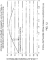
- the focal axis of the secondary mirror 70 is preferably located at or behind the primary mirror vertex 122 , and more preferably is located at a distance equal to the primary mirror 68 focal length F 1 behind the primary mirror 68 vertex.
- the results shown in Figure 12 indicate that the optimum amount of focused light occurs when the secondary mirror focal plane is located behind the primary mirror 68 vertex at a distance equal to the primary focal length F 1 .
- the optimum location increases the average amount of focused light by over 25% compared to the primary focal point location. Increasing the distance from the vertex 122 further causes the output beam to defocus and the amount of light decreases.
- the dual reflector system disclosed herein improves light collection efficiency and enables controlling of illumination beam size to best suit the application where illumination is needed. It improves the light uniformity of linear light sources such as linear arc lamps and strobed light.
- the system is more efficient than existing strobe flashlamp illuminators, is compact, all reflective (no colour), lightweight, simple and inexpensive to manufacture. These features result in increased illumination range, lower power requirements and better quality images from cameras that use this illuminator.
- the system has applications to machine vision, surveillance, spectroscopic inspection of materials, and converting linear light sources, such as tungsten halogen lamps, sodium lamps, metal halide lamps or fluorescent tubes, into rectangular beam spot lights (stage lights, projectors, vehicle headlights).
- the terms “comprises”, “comprising”, “including” and “includes” are to be construed as being inclusive and open ended, and not exclusive. Specifically, when used in this specification including claims, the terms “comprises”, “comprising”, “including” and “includes” and variations thereof mean the specified features, steps or components are included. These terms are not to be interpreted to exclude the presence of other features, steps or components.
Landscapes
- Engineering & Computer Science (AREA)
- General Engineering & Computer Science (AREA)
- Physics & Mathematics (AREA)
- General Physics & Mathematics (AREA)
- Optical Elements Other Than Lenses (AREA)
- Non-Portable Lighting Devices Or Systems Thereof (AREA)
Claims (23)
- Beleuchtungssystem, umfassend :ein Doppelreflektorsystem (60), umfassendeinen primären zylindrischen Reflektor (68), der eine primäre Brennachse aufweist und so ausgerichtet ist, dass er Licht in einer ersten Ebene kollimiert, undeinen sekundären zylindrischen Reflektor (70), der eine sekundäre Brennachse aufweist und so ausgerichtet ist, dass er Licht in einer zweiten Ebene kollimiert, wobei der primäre zylindrische Reflektor (68) und der sekundäre zylindrische Reflektor (70) sich orthogonal zueinander befinden ; undeine lineare Lichtquelle (74), die eine Emissionslänge (L2) aufweist, die auf der primären Brennachse angeordnet ist; wobeider primäre zylindrische Reflektor (68) und der sekundäre zylindrische Reflektor (70) relativ zueinander so ausgerichtet sind, dass von der linearen Lichtquelle (74) emittiertes Licht reflektiert wird und zu einem rechteckförmigen Strahl wird, der sowohl in der ersten Ebene als auch der zweiten Ebene kollimiert ist.
- Beleuchtungssystem nach Anspruch 1, wobei
der primäre zylindrische Reflektor (68) ein primärer zylindrischer Parabolreflektor ist, der einen primären Scheitelpunkt (122) und eine primäre Brennweite (F1) zwischen dem primären Scheitelpunkt (122) und der primären Brennachse aufweist; und
der sekundäre zylindrische Reflektor (70) ein sekundärer zylindrischer Parabolreflektor ist, der einen sekundären Scheitelpunkt (120) und eine sekundäre Brennweite (F2) zwischen dem sekundären Scheitelpunkt (120) und der sekundären Brennachse aufweist. - Beleuchtungssystem nach Anspruch 2, wobei die sekundäre Brennachse sich auf oder hinter dem primären Scheitelpunkt (122) befindet.
- Beleuchtungssystem nach Anspruch 3, wobei die sekundäre Brennachse sich hinter dem primären Scheitelpunkt (122) in einem Abstand gleich der primären Brennweite (F1) von dem primären Scheitelpunkt (122) befindet.
- Beleuchtungssystem nach Anspruch 2, wobei die sekundäre Brennweite (F2) größer oder gleich der Hälfte der Emissionslänge (L2) der linearen Lichtquelle (74) ist.
- Beleuchtungssystem nach Anspruch 2, wobei eines des primären Scheitelpunkts (122), des sekundären Scheitelpunkts (120), und der primäre und der sekundäre Scheitelpunkt gekrümmt ist bzw. sind.
- Beleuchtungssystem nach Anspruch 2, wobei eines des primären Scheitelpunkts (122), des sekundären Scheitelpunkts (120), und der primäre und der sekundäre Scheitelpunkt linear ist bzw. sind.
- Beleuchtungssystem nach einem der Ansprüche 1 bis 7, wobei die lineare Lichtquelle (74) eine einer Blitzlampe, einer zylindrischen linearen kontinuierlichen Lichtwellenquelle, einer Wolfram-Halogenlampe, einer Natriumlampe, einer Metallhalidlampe und einer Leuchtstofflampe ist.
- Beleuchtungssystem nach Anspruch 8, wobei die lineare Lichtquelle (74) eine Stroboskoplampe ist.
- Beleuchtungssystem nach einem der Ansprüche 1 bis 9, wobei das Doppelreflektorsystem weiter mindestens ein Spiegelsegment (80) beinhaltet, das parallel zu dem primären zylindrischen Reflektor (68) angeordnet ist und in Bezug auf den primären zylindrischen Reflektor (68) so ausgerichtet ist, dass es Streulicht durch die primäre Brennachse zurückreflektiert.
- Beleuchtungssystem nach Anspruch 10, wobei das mindestens eine Spiegelsegment (80) so angeordnet ist, dass durch die primäre Brennachse passierendes und von dem primären zylindrischen Reflektor (68) reflektiertes Licht nicht von dem mindestens einen Spiegelsegment (80) reflektiert wird.
- Beleuchtungssystem nach einem der Ansprüche 1 bis 11, wobei einer oder beide des primären zylindrischen Reflektors (68) und des sekundären zylindrischen Reflektors (70) mindestens einen flexiblen reflektierenden Materialbogen umfassen, der an Einsätzen (142) montiert ist.
- Beleuchtungssystem nach Anspruch 12, wobei die Einsätze (142) an einer Basis (62) montiert sind.
- Beleuchtungssystem nach Anspruch 12 oder 13, wobei die Einsätze (142) den flexiblen reflektierenden Materialbogen zu einer Parabelform formen.
- Beleuchtungssystem nach einem der Ansprüche 1 bis 11, wobei einer oder beide des primären zylindrischen Reflektors (68) und des sekundären zylindrischen Reflektors (70) aus reflektierendem Material gefräst sind.
- Beleuchtungssystem nach Anspruch 15, wobei das gefräste reflektierende Material auf einer Basis (62) montiert ist.
- Beleuchtungssystem nach Anspruch 15 oder 16, wobei eine Oberfläche des gefrästen reflektierenden Materials in Form einer Parabel vorliegt.
- Beleuchtungssystem nach einem der Ansprüche 1 bis 17, wobei der primäre zylindrische Reflektor (68) und der sekundäre zylindrische Reflektor (70) in Bezug zueinander verstellbar angeordnet und ausgerichtet sind.
- Beleuchtungssystem nach Anspruch 18, wobei die lineare Lichtquelle (74) eine Längsachse entlang der Emissionslänge aufweist, und wobei die lineare Lichtquelle (74) in Bezug auf den primären zylindrischen Reflektor (68) fixiert ist, mit ihrer Längsachse entlang der Brennachse des primären zylindrischen Reflektors (68) gefluchtet.
- Beleuchtungssystem nach Anspruch 18, wobei der primäre zylindrische Reflektor (68) sich in Bezug zu dem sekundären zylindrischen Reflektor (70) in einer Ebene senkrecht zu der sekundären Brennachse verschieben und rotieren kann.
- Beleuchtungssystem nach einem der Ansprüche 1 bis 20, wobei der primäre zylindrische Reflektor (68) zwei gerade Kanten (132, 134) aufweist und die primäre Brennachse zwischen dem primären zylindrischen Reflektor (68) und einer durch die zwei geraden Kanten (132, 134) definierten Ebene (136) liegt.
- Beleuchtungssystem nach einem der Ansprüche 1 bis 21, wobei ein Teil des primären zylindrischen Reflektors (68) parabelförmig ist und ein restlicher Teil des primären generell zylindrischen Reflektors um die lineare Lichtquelle (74) herum verläuft.
- Beleuchtungssystem nach Anspruch 22, wobei der Teil des primären zylindrischen Reflektors (68), der um die lineare Lichtquelle (74) herum verläuft, in Form eines Kreises vorliegt, und wobei die lineare Lichtquelle (74) in einem Zentrum dieses Kreises angeordnet ist.
Applications Claiming Priority (2)
| Application Number | Priority Date | Filing Date | Title |
|---|---|---|---|
| US12/907,685 US9115867B2 (en) | 2010-10-19 | 2010-10-19 | Dual reflector system for linear lamp illuminators |
| PCT/CA2011/050659 WO2012051716A1 (en) | 2010-10-19 | 2011-10-19 | Dual reflector system for linear lamp illuminators |
Publications (3)
| Publication Number | Publication Date |
|---|---|
| EP2633231A1 EP2633231A1 (de) | 2013-09-04 |
| EP2633231A4 EP2633231A4 (de) | 2014-11-19 |
| EP2633231B1 true EP2633231B1 (de) | 2018-03-28 |
Family
ID=45934016
Family Applications (1)
| Application Number | Title | Priority Date | Filing Date |
|---|---|---|---|
| EP11833680.9A Active EP2633231B1 (de) | 2010-10-19 | 2011-10-19 | Doppelreflektorsystem für lineare lampenbeleuchtungskörper |
Country Status (4)
| Country | Link |
|---|---|
| US (1) | US9115867B2 (de) |
| EP (1) | EP2633231B1 (de) |
| CA (1) | CA2824198C (de) |
| WO (1) | WO2012051716A1 (de) |
Families Citing this family (42)
| Publication number | Priority date | Publication date | Assignee | Title |
|---|---|---|---|---|
| US9052083B2 (en) * | 2008-10-31 | 2015-06-09 | Code 3, Inc. | Light fixture with inner and outer trough reflectors |
| US9335038B2 (en) | 2011-07-20 | 2016-05-10 | Ip Holdings, Llc | Vertically disposed HID lamp fixture |
| USD770079S1 (en) | 2015-04-02 | 2016-10-25 | Ip Holdings, Llc | Light fixture |
| WO2014059345A1 (en) * | 2012-10-12 | 2014-04-17 | Lehmann Kevin K | Mercury vapor trace detection using pre-excitation cavity ring down spectroscopy |
| CN109602561A (zh) * | 2013-01-30 | 2019-04-12 | 通用电气公司 | 婴儿保暖设备及组装婴儿保暖设备的方法 |
| USD698986S1 (en) * | 2013-03-27 | 2014-02-04 | Ip Holdings, Llc | Horticulture grow light housing |
| USD698987S1 (en) | 2013-06-20 | 2014-02-04 | Ip Holdings, Llc | Horticulture grow light housing |
| USD745993S1 (en) | 2013-07-09 | 2015-12-22 | Ip Holdings, Llc | Horticulture grow light housing |
| US9016907B2 (en) | 2013-07-18 | 2015-04-28 | Ip Holdings, Llc | Air cooled horticulture lighting fixture for a double ended high pressure sodium lamp |
| US9750199B2 (en) | 2013-07-18 | 2017-09-05 | Ip Holdings, Llc | Air cooled horticulture lighting fixture |
| USD748849S1 (en) | 2014-06-11 | 2016-02-02 | Ip Holdings, Llc | Sealed optics air cooled grow light |
| US9593825B2 (en) * | 2013-10-29 | 2017-03-14 | Microscan Systems, Inc. | Illumination system |
| SE537987C2 (sv) * | 2014-04-07 | 2016-01-12 | Cgrain Ab | Avbildningssystem för granulärt material med homogen bakgrund |
| USD732235S1 (en) | 2014-08-07 | 2015-06-16 | Ip Holdings, Llc | Horticulture grow light |
| USD732236S1 (en) * | 2014-09-11 | 2015-06-16 | Ip Holdings, Llc | Light fixture |
| USD748847S1 (en) * | 2014-10-17 | 2016-02-02 | Surna Inc. | Liquid-cooled optical reflector |
| USD748319S1 (en) * | 2014-10-17 | 2016-01-26 | Surna Inc. | Vented optical reflector |
| USD748850S1 (en) * | 2014-10-17 | 2016-02-02 | Surna Inc. | Air-cooled optical reflector |
| USD748320S1 (en) * | 2014-11-11 | 2016-01-26 | Surna Inc. | Liquid-cooled optical reflector |
| USD751245S1 (en) | 2014-12-11 | 2016-03-08 | Ip Holdings, Llc | Horticulture grow light |
| USD757346S1 (en) | 2015-01-08 | 2016-05-24 | Ip Holdings, Llc | Horticulture grow light |
| USD773107S1 (en) | 2015-04-13 | 2016-11-29 | Ip Holdings, Llc | Horticulture grow light |
| USD769513S1 (en) | 2015-04-15 | 2016-10-18 | Ip Holdings, Llc | Light fixture |
| USD770670S1 (en) | 2015-06-24 | 2016-11-01 | Ip Holdings, Llc | Horticulture grow light |
| DE202015106256U1 (de) * | 2015-11-18 | 2017-02-22 | Zumtobel Lighting Gmbh | Blendarme Lichttechnik |
| USD780985S1 (en) | 2016-01-05 | 2017-03-07 | Ip Holdings, Llc | Light fixture |
| USD780986S1 (en) | 2016-01-07 | 2017-03-07 | Ip Holdings, Llc | Light fixture |
| USD796728S1 (en) | 2016-06-06 | 2017-09-05 | Ip Holdings, Llc | Light fixture |
| USD804078S1 (en) | 2016-08-31 | 2017-11-28 | Ip Holdings, Llc | Light fixture |
| USD804079S1 (en) | 2016-08-31 | 2017-11-28 | Ip Holdings, Llc | Light fixture |
| USD797350S1 (en) | 2016-11-01 | 2017-09-12 | Ip Holdings, Llc | Light fixture |
| USD822882S1 (en) | 2017-05-17 | 2018-07-10 | Ip Holdings, Llc | Horticulture grow light |
| USD843049S1 (en) | 2017-09-14 | 2019-03-12 | Hgci, Inc. | Horticulture grow light |
| USD842532S1 (en) | 2017-10-25 | 2019-03-05 | Hgci, Inc. | Light fixture |
| USD871654S1 (en) | 2017-10-30 | 2019-12-31 | Hgci, Inc. | Light fixture |
| USD848663S1 (en) | 2017-11-03 | 2019-05-14 | Hgci, Inc. | Light fixture |
| USD848664S1 (en) | 2017-11-07 | 2019-05-14 | Hgci, Inc. | Light fixture |
| USD848665S1 (en) | 2017-11-08 | 2019-05-14 | Hgci, Inc. | Horticulture grow light |
| DE102019118557A1 (de) | 2019-07-09 | 2021-01-14 | Chromasens Gmbh | Zweidimensionales Beleuchtungssystem |
| US11274809B2 (en) | 2020-02-21 | 2022-03-15 | Francis J. Henkel | Portable beach volleyball lighting system |
| US10976030B1 (en) | 2020-02-21 | 2021-04-13 | Francis J. Henkel | Portable beach volleyball lighting system |
| JP2025541263A (ja) * | 2022-12-13 | 2025-12-18 | マクドナルド・デトワイラー・アンド・アソシエイツ・コーポレーション | アンテナステアリングのためのアンテナシステムおよび方法 |
Family Cites Families (18)
| Publication number | Priority date | Publication date | Assignee | Title |
|---|---|---|---|---|
| US2252246A (en) | 1941-08-12 | Optical system | ||
| US3254342A (en) | 1963-07-09 | 1966-05-31 | Bell Telephone Labor Inc | Antenna system wherein beamwidth variation is achieved by changing shape of intermediate reflector |
| US3938162A (en) | 1974-08-27 | 1976-02-10 | The United States Of America As Represented By The United States National Aeronautics And Space Administration Office Of General Counsel-Code Gp | Variable beamwidth antenna |
| NL7608162A (nl) | 1976-07-22 | 1978-01-24 | Vaclav Josef Vokurka | Antenne in het bijzonder voor meet- doeleinden. |
| SE406636B (sv) | 1978-01-30 | 1979-02-19 | Laser Max | Anordning vid reflektor for lostagbar anbringning vid en normalglodlampa |
| US4755916A (en) | 1981-07-23 | 1988-07-05 | Collins Dynamics | Combined flood and spot light |
| US4947292A (en) | 1988-11-08 | 1990-08-07 | Vlah John A | Lighting system |
| US5235470A (en) | 1989-12-21 | 1993-08-10 | Cheng Dah Y | Orthogonal parabolic reflector systems |
| US5037191A (en) | 1989-12-21 | 1991-08-06 | Cheng Dah Y | Orthogonal parabolic reflector systems |
| US6536921B1 (en) | 1993-01-21 | 2003-03-25 | Jerome H. Simon | Architectural lighting distributed from contained radially collimated light and compact efficient luminaires |
| US5618102A (en) * | 1995-06-07 | 1997-04-08 | Adac Plastics, Inc. | Plasma discharge lamp |
| US5897183A (en) * | 1997-08-06 | 1999-04-27 | Rockwell Science Center, Inc. | External luminaire for panel or rack mounted display units |
| US6454442B1 (en) * | 1999-07-09 | 2002-09-24 | David G. Changaris | Device for soft irradiation |
| US6634759B1 (en) * | 2000-03-27 | 2003-10-21 | Cogent Light Technologies, Inc. | Coupling of light from a light source to a target using dual ellipsoidal reflectors |
| CA2437059A1 (en) * | 2001-02-21 | 2002-09-26 | Wavien, Inc. | Illumination system using filament lamps |
| FR2881509B1 (fr) | 2005-02-01 | 2007-03-16 | Valeo Vision Sa | Projecteur verticalise pour vehicule automobile |
| JP4524265B2 (ja) | 2005-03-30 | 2010-08-11 | 三星電子株式会社 | 照明ユニット及びそれを採用した画像投射装置 |
| US7556399B1 (en) | 2006-01-25 | 2009-07-07 | Bailey Michael L | Light reflector assembly having opposed reflector sections |
-
2010
- 2010-10-19 US US12/907,685 patent/US9115867B2/en active Active
-
2011
- 2011-10-19 EP EP11833680.9A patent/EP2633231B1/de active Active
- 2011-10-19 CA CA2824198A patent/CA2824198C/en active Active
- 2011-10-19 WO PCT/CA2011/050659 patent/WO2012051716A1/en not_active Ceased
Non-Patent Citations (1)
| Title |
|---|
| None * |
Also Published As
| Publication number | Publication date |
|---|---|
| EP2633231A4 (de) | 2014-11-19 |
| CA2824198C (en) | 2017-02-21 |
| CA2824198A1 (en) | 2012-04-26 |
| WO2012051716A1 (en) | 2012-04-26 |
| US9115867B2 (en) | 2015-08-25 |
| US20120092859A1 (en) | 2012-04-19 |
| EP2633231A1 (de) | 2013-09-04 |
Similar Documents
| Publication | Publication Date | Title |
|---|---|---|
| US9115867B2 (en) | Dual reflector system for linear lamp illuminators | |
| KR102841260B1 (ko) | 적어도 두 개의 콜렉터의 피조면을 이미지화하는 발광 장치 | |
| JP4954288B2 (ja) | 反射投光器 | |
| CN1208649C (zh) | 使用双椭球反射镜将光源的光耦合到目标 | |
| JP3153890B2 (ja) | 凹面のトロイダル反射鏡を使用して集束及び収集する光学システム | |
| JP6247451B2 (ja) | ライトモジュール | |
| JP3224387B2 (ja) | 光線抽出フィルム | |
| JP4348037B2 (ja) | パラボラリフレクタまたはリフレクタの対応の楕円面/双曲面対を使用する集光システム | |
| JP3847927B2 (ja) | 発光管及びそれを用いた光源装置 | |
| US6499862B1 (en) | Spotlight with an adjustable angle of radiation and with an aspherical front lens | |
| CN113238373B (zh) | 一种激光扫描单元及激光打印机 | |
| EP1795863B1 (de) | Optische Vorrichtung | |
| JPH05505683A (ja) | 直交放物面反射器システム | |
| JP6999064B2 (ja) | 自動車投光装置 | |
| JP2007534973A (ja) | 照明の集光および整形に関する装置および方法 | |
| TW504555B (en) | Concentrating and collecting optical system using concave toroidal reflectors | |
| JP4987866B2 (ja) | 最適化された倍率を有するデュアル放物面状リフレクタおよびデュアル楕円面状リフレクタシステム | |
| US12000566B2 (en) | Spotlight | |
| JP3299780B2 (ja) | カメラ用ストロボ機構 | |
| CN223460288U (zh) | 一种适用于角雾灯近光展宽功能的光学系统及车灯 | |
| US20250161520A1 (en) | Device for air treatment by means of uv radiation and assembly with this device | |
| JPWO2005062115A1 (ja) | 光源及び発散角制御方法 | |
| JP3477451B2 (ja) | カメラ用ストロボ機構 | |
| JPH0565001U (ja) | ビデオ用投光器 | |
| KR20180003213A (ko) | 곡면거울을 반사경으로 활용한 led 조명등 |
Legal Events
| Date | Code | Title | Description |
|---|---|---|---|
| PUAI | Public reference made under article 153(3) epc to a published international application that has entered the european phase |
Free format text: ORIGINAL CODE: 0009012 |
|
| 17P | Request for examination filed |
Effective date: 20130710 |
|
| AK | Designated contracting states |
Kind code of ref document: A1 Designated state(s): AL AT BE BG CH CY CZ DE DK EE ES FI FR GB GR HR HU IE IS IT LI LT LU LV MC MK MT NL NO PL PT RO RS SE SI SK SM TR |
|
| DAX | Request for extension of the european patent (deleted) | ||
| RAP1 | Party data changed (applicant data changed or rights of an application transferred) |
Owner name: MACDONALD, DETTWILER AND ASSOCIATES INC. |
|
| A4 | Supplementary search report drawn up and despatched |
Effective date: 20141016 |
|
| RIC1 | Information provided on ipc code assigned before grant |
Ipc: F21V 7/09 20060101AFI20141010BHEP Ipc: G03B 15/03 20060101ALI20141010BHEP Ipc: F21S 8/10 20060101ALI20141010BHEP |
|
| 17Q | First examination report despatched |
Effective date: 20150826 |
|
| STAA | Information on the status of an ep patent application or granted ep patent |
Free format text: STATUS: EXAMINATION IS IN PROGRESS |
|
| GRAP | Despatch of communication of intention to grant a patent |
Free format text: ORIGINAL CODE: EPIDOSNIGR1 |
|
| STAA | Information on the status of an ep patent application or granted ep patent |
Free format text: STATUS: GRANT OF PATENT IS INTENDED |
|
| INTG | Intention to grant announced |
Effective date: 20171009 |
|
| GRAS | Grant fee paid |
Free format text: ORIGINAL CODE: EPIDOSNIGR3 |
|
| GRAA | (expected) grant |
Free format text: ORIGINAL CODE: 0009210 |
|
| STAA | Information on the status of an ep patent application or granted ep patent |
Free format text: STATUS: THE PATENT HAS BEEN GRANTED |
|
| AK | Designated contracting states |
Kind code of ref document: B1 Designated state(s): AL AT BE BG CH CY CZ DE DK EE ES FI FR GB GR HR HU IE IS IT LI LT LU LV MC MK MT NL NO PL PT RO RS SE SI SK SM TR |
|
| REG | Reference to a national code |
Ref country code: GB Ref legal event code: FG4D |
|
| REG | Reference to a national code |
Ref country code: CH Ref legal event code: EP |
|
| REG | Reference to a national code |
Ref country code: AT Ref legal event code: REF Ref document number: 983774 Country of ref document: AT Kind code of ref document: T Effective date: 20180415 |
|
| REG | Reference to a national code |
Ref country code: IE Ref legal event code: FG4D |
|
| REG | Reference to a national code |
Ref country code: DE Ref legal event code: R096 Ref document number: 602011046990 Country of ref document: DE |
|
| REG | Reference to a national code |
Ref country code: CH Ref legal event code: NV Representative=s name: DR. ALEXANDER MILLER, LL.M. RECHTSANWALT (D), CH |
|
| REG | Reference to a national code |
Ref country code: SE Ref legal event code: TRGR |
|
| PG25 | Lapsed in a contracting state [announced via postgrant information from national office to epo] |
Ref country code: LT Free format text: LAPSE BECAUSE OF FAILURE TO SUBMIT A TRANSLATION OF THE DESCRIPTION OR TO PAY THE FEE WITHIN THE PRESCRIBED TIME-LIMIT Effective date: 20180328 Ref country code: HR Free format text: LAPSE BECAUSE OF FAILURE TO SUBMIT A TRANSLATION OF THE DESCRIPTION OR TO PAY THE FEE WITHIN THE PRESCRIBED TIME-LIMIT Effective date: 20180328 |
|
| REG | Reference to a national code |
Ref country code: NL Ref legal event code: MP Effective date: 20180328 |
|
| REG | Reference to a national code |
Ref country code: LT Ref legal event code: MG4D |
|
| REG | Reference to a national code |
Ref country code: NO Ref legal event code: T2 Effective date: 20180328 |
|
| PG25 | Lapsed in a contracting state [announced via postgrant information from national office to epo] |
Ref country code: LV Free format text: LAPSE BECAUSE OF FAILURE TO SUBMIT A TRANSLATION OF THE DESCRIPTION OR TO PAY THE FEE WITHIN THE PRESCRIBED TIME-LIMIT Effective date: 20180328 Ref country code: GR Free format text: LAPSE BECAUSE OF FAILURE TO SUBMIT A TRANSLATION OF THE DESCRIPTION OR TO PAY THE FEE WITHIN THE PRESCRIBED TIME-LIMIT Effective date: 20180629 Ref country code: RS Free format text: LAPSE BECAUSE OF FAILURE TO SUBMIT A TRANSLATION OF THE DESCRIPTION OR TO PAY THE FEE WITHIN THE PRESCRIBED TIME-LIMIT Effective date: 20180328 Ref country code: BG Free format text: LAPSE BECAUSE OF FAILURE TO SUBMIT A TRANSLATION OF THE DESCRIPTION OR TO PAY THE FEE WITHIN THE PRESCRIBED TIME-LIMIT Effective date: 20180628 |
|
| REG | Reference to a national code |
Ref country code: FR Ref legal event code: PLFP Year of fee payment: 8 |
|
| PG25 | Lapsed in a contracting state [announced via postgrant information from national office to epo] |
Ref country code: IT Free format text: LAPSE BECAUSE OF FAILURE TO SUBMIT A TRANSLATION OF THE DESCRIPTION OR TO PAY THE FEE WITHIN THE PRESCRIBED TIME-LIMIT Effective date: 20180328 Ref country code: AL Free format text: LAPSE BECAUSE OF FAILURE TO SUBMIT A TRANSLATION OF THE DESCRIPTION OR TO PAY THE FEE WITHIN THE PRESCRIBED TIME-LIMIT Effective date: 20180328 Ref country code: PL Free format text: LAPSE BECAUSE OF FAILURE TO SUBMIT A TRANSLATION OF THE DESCRIPTION OR TO PAY THE FEE WITHIN THE PRESCRIBED TIME-LIMIT Effective date: 20180328 Ref country code: NL Free format text: LAPSE BECAUSE OF FAILURE TO SUBMIT A TRANSLATION OF THE DESCRIPTION OR TO PAY THE FEE WITHIN THE PRESCRIBED TIME-LIMIT Effective date: 20180328 Ref country code: EE Free format text: LAPSE BECAUSE OF FAILURE TO SUBMIT A TRANSLATION OF THE DESCRIPTION OR TO PAY THE FEE WITHIN THE PRESCRIBED TIME-LIMIT Effective date: 20180328 Ref country code: ES Free format text: LAPSE BECAUSE OF FAILURE TO SUBMIT A TRANSLATION OF THE DESCRIPTION OR TO PAY THE FEE WITHIN THE PRESCRIBED TIME-LIMIT Effective date: 20180328 Ref country code: RO Free format text: LAPSE BECAUSE OF FAILURE TO SUBMIT A TRANSLATION OF THE DESCRIPTION OR TO PAY THE FEE WITHIN THE PRESCRIBED TIME-LIMIT Effective date: 20180328 |
|
| PG25 | Lapsed in a contracting state [announced via postgrant information from national office to epo] |
Ref country code: SM Free format text: LAPSE BECAUSE OF FAILURE TO SUBMIT A TRANSLATION OF THE DESCRIPTION OR TO PAY THE FEE WITHIN THE PRESCRIBED TIME-LIMIT Effective date: 20180328 Ref country code: CZ Free format text: LAPSE BECAUSE OF FAILURE TO SUBMIT A TRANSLATION OF THE DESCRIPTION OR TO PAY THE FEE WITHIN THE PRESCRIBED TIME-LIMIT Effective date: 20180328 Ref country code: SK Free format text: LAPSE BECAUSE OF FAILURE TO SUBMIT A TRANSLATION OF THE DESCRIPTION OR TO PAY THE FEE WITHIN THE PRESCRIBED TIME-LIMIT Effective date: 20180328 |
|
| REG | Reference to a national code |
Ref country code: AT Ref legal event code: MK05 Ref document number: 983774 Country of ref document: AT Kind code of ref document: T Effective date: 20180328 |
|
| PG25 | Lapsed in a contracting state [announced via postgrant information from national office to epo] |
Ref country code: PT Free format text: LAPSE BECAUSE OF FAILURE TO SUBMIT A TRANSLATION OF THE DESCRIPTION OR TO PAY THE FEE WITHIN THE PRESCRIBED TIME-LIMIT Effective date: 20180730 |
|
| RIC2 | Information provided on ipc code assigned after grant |
Ipc: G03B 15/03 20060101ALI20141010BHEP Ipc: F21V 7/09 20060101AFI20141010BHEP Ipc: F21S 8/10 20181130ALI20141010BHEP |
|
| REG | Reference to a national code |
Ref country code: DE Ref legal event code: R097 Ref document number: 602011046990 Country of ref document: DE |
|
| REG | Reference to a national code |
Ref country code: CH Ref legal event code: PK Free format text: BERICHTIGUNGEN |
|
| PG25 | Lapsed in a contracting state [announced via postgrant information from national office to epo] |
Ref country code: AT Free format text: LAPSE BECAUSE OF FAILURE TO SUBMIT A TRANSLATION OF THE DESCRIPTION OR TO PAY THE FEE WITHIN THE PRESCRIBED TIME-LIMIT Effective date: 20180328 Ref country code: DK Free format text: LAPSE BECAUSE OF FAILURE TO SUBMIT A TRANSLATION OF THE DESCRIPTION OR TO PAY THE FEE WITHIN THE PRESCRIBED TIME-LIMIT Effective date: 20180328 |
|
| REG | Reference to a national code |
Ref country code: CH Ref legal event code: PK Free format text: BERICHTIGUNGEN |
|
| PLBE | No opposition filed within time limit |
Free format text: ORIGINAL CODE: 0009261 |
|
| STAA | Information on the status of an ep patent application or granted ep patent |
Free format text: STATUS: NO OPPOSITION FILED WITHIN TIME LIMIT |
|
| RIC2 | Information provided on ipc code assigned after grant |
Ipc: G03B 15/03 20060101ALI20141010BHEP Ipc: F21S 8/10 20060101ALI20141010BHEP Ipc: F21V 7/09 20060101AFI20141010BHEP |
|
| 26N | No opposition filed |
Effective date: 20190103 |
|
| PG25 | Lapsed in a contracting state [announced via postgrant information from national office to epo] |
Ref country code: SI Free format text: LAPSE BECAUSE OF FAILURE TO SUBMIT A TRANSLATION OF THE DESCRIPTION OR TO PAY THE FEE WITHIN THE PRESCRIBED TIME-LIMIT Effective date: 20180328 |
|
| REG | Reference to a national code |
Ref country code: BE Ref legal event code: MM Effective date: 20181031 |
|
| PG25 | Lapsed in a contracting state [announced via postgrant information from national office to epo] |
Ref country code: MC Free format text: LAPSE BECAUSE OF FAILURE TO SUBMIT A TRANSLATION OF THE DESCRIPTION OR TO PAY THE FEE WITHIN THE PRESCRIBED TIME-LIMIT Effective date: 20180328 Ref country code: LU Free format text: LAPSE BECAUSE OF NON-PAYMENT OF DUE FEES Effective date: 20181019 |
|
| REG | Reference to a national code |
Ref country code: IE Ref legal event code: MM4A |
|
| PG25 | Lapsed in a contracting state [announced via postgrant information from national office to epo] |
Ref country code: BE Free format text: LAPSE BECAUSE OF NON-PAYMENT OF DUE FEES Effective date: 20181031 |
|
| PG25 | Lapsed in a contracting state [announced via postgrant information from national office to epo] |
Ref country code: IE Free format text: LAPSE BECAUSE OF NON-PAYMENT OF DUE FEES Effective date: 20181019 |
|
| PG25 | Lapsed in a contracting state [announced via postgrant information from national office to epo] |
Ref country code: MT Free format text: LAPSE BECAUSE OF NON-PAYMENT OF DUE FEES Effective date: 20181019 |
|
| PG25 | Lapsed in a contracting state [announced via postgrant information from national office to epo] |
Ref country code: TR Free format text: LAPSE BECAUSE OF FAILURE TO SUBMIT A TRANSLATION OF THE DESCRIPTION OR TO PAY THE FEE WITHIN THE PRESCRIBED TIME-LIMIT Effective date: 20180328 |
|
| PG25 | Lapsed in a contracting state [announced via postgrant information from national office to epo] |
Ref country code: HU Free format text: LAPSE BECAUSE OF FAILURE TO SUBMIT A TRANSLATION OF THE DESCRIPTION OR TO PAY THE FEE WITHIN THE PRESCRIBED TIME-LIMIT; INVALID AB INITIO Effective date: 20111019 Ref country code: CY Free format text: LAPSE BECAUSE OF FAILURE TO SUBMIT A TRANSLATION OF THE DESCRIPTION OR TO PAY THE FEE WITHIN THE PRESCRIBED TIME-LIMIT Effective date: 20180328 Ref country code: MK Free format text: LAPSE BECAUSE OF NON-PAYMENT OF DUE FEES Effective date: 20180328 |
|
| PG25 | Lapsed in a contracting state [announced via postgrant information from national office to epo] |
Ref country code: IS Free format text: LAPSE BECAUSE OF FAILURE TO SUBMIT A TRANSLATION OF THE DESCRIPTION OR TO PAY THE FEE WITHIN THE PRESCRIBED TIME-LIMIT Effective date: 20180728 |
|
| REG | Reference to a national code |
Ref country code: DE Ref legal event code: R082 Ref document number: 602011046990 Country of ref document: DE Representative=s name: LECOMTE, DIDIER, LU |
|
| REG | Reference to a national code |
Ref country code: CH Ref legal event code: U11 Free format text: ST27 STATUS EVENT CODE: U-0-0-U10-U11 (AS PROVIDED BY THE NATIONAL OFFICE) Effective date: 20251101 |
|
| PGFP | Annual fee paid to national office [announced via postgrant information from national office to epo] |
Ref country code: DE Payment date: 20251021 Year of fee payment: 15 |
|
| PGFP | Annual fee paid to national office [announced via postgrant information from national office to epo] |
Ref country code: GB Payment date: 20251022 Year of fee payment: 15 |
|
| PGFP | Annual fee paid to national office [announced via postgrant information from national office to epo] |
Ref country code: NO Payment date: 20251024 Year of fee payment: 15 |
|
| PGFP | Annual fee paid to national office [announced via postgrant information from national office to epo] |
Ref country code: FI Payment date: 20251028 Year of fee payment: 15 |
|
| PGFP | Annual fee paid to national office [announced via postgrant information from national office to epo] |
Ref country code: FR Payment date: 20251030 Year of fee payment: 15 |
|
| PGFP | Annual fee paid to national office [announced via postgrant information from national office to epo] |
Ref country code: SE Payment date: 20251021 Year of fee payment: 15 Ref country code: CH Payment date: 20251101 Year of fee payment: 15 |