EP2633095B1 - Molybdänmonoxidschichten und deren herstellung mittels pvd - Google Patents
Molybdänmonoxidschichten und deren herstellung mittels pvd Download PDFInfo
- Publication number
- EP2633095B1 EP2633095B1 EP11779086.5A EP11779086A EP2633095B1 EP 2633095 B1 EP2633095 B1 EP 2633095B1 EP 11779086 A EP11779086 A EP 11779086A EP 2633095 B1 EP2633095 B1 EP 2633095B1
- Authority
- EP
- European Patent Office
- Prior art keywords
- layer
- molybdenum
- coating
- moo
- oxygen
- Prior art date
- Legal status (The legal status is an assumption and is not a legal conclusion. Google has not performed a legal analysis and makes no representation as to the accuracy of the status listed.)
- Not-in-force
Links
Images

Classifications
-
- C—CHEMISTRY; METALLURGY
- C23—COATING METALLIC MATERIAL; COATING MATERIAL WITH METALLIC MATERIAL; CHEMICAL SURFACE TREATMENT; DIFFUSION TREATMENT OF METALLIC MATERIAL; COATING BY VACUUM EVAPORATION, BY SPUTTERING, BY ION IMPLANTATION OR BY CHEMICAL VAPOUR DEPOSITION, IN GENERAL; INHIBITING CORROSION OF METALLIC MATERIAL OR INCRUSTATION IN GENERAL
- C23C—COATING METALLIC MATERIAL; COATING MATERIAL WITH METALLIC MATERIAL; SURFACE TREATMENT OF METALLIC MATERIAL BY DIFFUSION INTO THE SURFACE, BY CHEMICAL CONVERSION OR SUBSTITUTION; COATING BY VACUUM EVAPORATION, BY SPUTTERING, BY ION IMPLANTATION OR BY CHEMICAL VAPOUR DEPOSITION, IN GENERAL
- C23C14/00—Coating by vacuum evaporation, by sputtering or by ion implantation of the coating forming material
- C23C14/06—Coating by vacuum evaporation, by sputtering or by ion implantation of the coating forming material characterised by the coating material
- C23C14/08—Oxides
-
- C—CHEMISTRY; METALLURGY
- C10—PETROLEUM, GAS OR COKE INDUSTRIES; TECHNICAL GASES CONTAINING CARBON MONOXIDE; FUELS; LUBRICANTS; PEAT
- C10M—LUBRICATING COMPOSITIONS; USE OF CHEMICAL SUBSTANCES EITHER ALONE OR AS LUBRICATING INGREDIENTS IN A LUBRICATING COMPOSITION
- C10M103/00—Lubricating compositions characterised by the base-material being an inorganic material
- C10M103/06—Metal compounds
-
- C—CHEMISTRY; METALLURGY
- C23—COATING METALLIC MATERIAL; COATING MATERIAL WITH METALLIC MATERIAL; CHEMICAL SURFACE TREATMENT; DIFFUSION TREATMENT OF METALLIC MATERIAL; COATING BY VACUUM EVAPORATION, BY SPUTTERING, BY ION IMPLANTATION OR BY CHEMICAL VAPOUR DEPOSITION, IN GENERAL; INHIBITING CORROSION OF METALLIC MATERIAL OR INCRUSTATION IN GENERAL
- C23C—COATING METALLIC MATERIAL; COATING MATERIAL WITH METALLIC MATERIAL; SURFACE TREATMENT OF METALLIC MATERIAL BY DIFFUSION INTO THE SURFACE, BY CHEMICAL CONVERSION OR SUBSTITUTION; COATING BY VACUUM EVAPORATION, BY SPUTTERING, BY ION IMPLANTATION OR BY CHEMICAL VAPOUR DEPOSITION, IN GENERAL
- C23C14/00—Coating by vacuum evaporation, by sputtering or by ion implantation of the coating forming material
- C23C14/06—Coating by vacuum evaporation, by sputtering or by ion implantation of the coating forming material characterised by the coating material
-
- C—CHEMISTRY; METALLURGY
- C23—COATING METALLIC MATERIAL; COATING MATERIAL WITH METALLIC MATERIAL; CHEMICAL SURFACE TREATMENT; DIFFUSION TREATMENT OF METALLIC MATERIAL; COATING BY VACUUM EVAPORATION, BY SPUTTERING, BY ION IMPLANTATION OR BY CHEMICAL VAPOUR DEPOSITION, IN GENERAL; INHIBITING CORROSION OF METALLIC MATERIAL OR INCRUSTATION IN GENERAL
- C23C—COATING METALLIC MATERIAL; COATING MATERIAL WITH METALLIC MATERIAL; SURFACE TREATMENT OF METALLIC MATERIAL BY DIFFUSION INTO THE SURFACE, BY CHEMICAL CONVERSION OR SUBSTITUTION; COATING BY VACUUM EVAPORATION, BY SPUTTERING, BY ION IMPLANTATION OR BY CHEMICAL VAPOUR DEPOSITION, IN GENERAL
- C23C14/00—Coating by vacuum evaporation, by sputtering or by ion implantation of the coating forming material
- C23C14/0021—Reactive sputtering or evaporation
- C23C14/0036—Reactive sputtering
- C23C14/0084—Producing gradient compositions
-
- C—CHEMISTRY; METALLURGY
- C23—COATING METALLIC MATERIAL; COATING MATERIAL WITH METALLIC MATERIAL; CHEMICAL SURFACE TREATMENT; DIFFUSION TREATMENT OF METALLIC MATERIAL; COATING BY VACUUM EVAPORATION, BY SPUTTERING, BY ION IMPLANTATION OR BY CHEMICAL VAPOUR DEPOSITION, IN GENERAL; INHIBITING CORROSION OF METALLIC MATERIAL OR INCRUSTATION IN GENERAL
- C23C—COATING METALLIC MATERIAL; COATING MATERIAL WITH METALLIC MATERIAL; SURFACE TREATMENT OF METALLIC MATERIAL BY DIFFUSION INTO THE SURFACE, BY CHEMICAL CONVERSION OR SUBSTITUTION; COATING BY VACUUM EVAPORATION, BY SPUTTERING, BY ION IMPLANTATION OR BY CHEMICAL VAPOUR DEPOSITION, IN GENERAL
- C23C14/00—Coating by vacuum evaporation, by sputtering or by ion implantation of the coating forming material
- C23C14/02—Pretreatment of the material to be coated
- C23C14/024—Deposition of sublayers, e.g. to promote adhesion of the coating
-
- C—CHEMISTRY; METALLURGY
- C23—COATING METALLIC MATERIAL; COATING MATERIAL WITH METALLIC MATERIAL; CHEMICAL SURFACE TREATMENT; DIFFUSION TREATMENT OF METALLIC MATERIAL; COATING BY VACUUM EVAPORATION, BY SPUTTERING, BY ION IMPLANTATION OR BY CHEMICAL VAPOUR DEPOSITION, IN GENERAL; INHIBITING CORROSION OF METALLIC MATERIAL OR INCRUSTATION IN GENERAL
- C23C—COATING METALLIC MATERIAL; COATING MATERIAL WITH METALLIC MATERIAL; SURFACE TREATMENT OF METALLIC MATERIAL BY DIFFUSION INTO THE SURFACE, BY CHEMICAL CONVERSION OR SUBSTITUTION; COATING BY VACUUM EVAPORATION, BY SPUTTERING, BY ION IMPLANTATION OR BY CHEMICAL VAPOUR DEPOSITION, IN GENERAL
- C23C14/00—Coating by vacuum evaporation, by sputtering or by ion implantation of the coating forming material
- C23C14/02—Pretreatment of the material to be coated
- C23C14/027—Graded interfaces
-
- C—CHEMISTRY; METALLURGY
- C23—COATING METALLIC MATERIAL; COATING MATERIAL WITH METALLIC MATERIAL; CHEMICAL SURFACE TREATMENT; DIFFUSION TREATMENT OF METALLIC MATERIAL; COATING BY VACUUM EVAPORATION, BY SPUTTERING, BY ION IMPLANTATION OR BY CHEMICAL VAPOUR DEPOSITION, IN GENERAL; INHIBITING CORROSION OF METALLIC MATERIAL OR INCRUSTATION IN GENERAL
- C23C—COATING METALLIC MATERIAL; COATING MATERIAL WITH METALLIC MATERIAL; SURFACE TREATMENT OF METALLIC MATERIAL BY DIFFUSION INTO THE SURFACE, BY CHEMICAL CONVERSION OR SUBSTITUTION; COATING BY VACUUM EVAPORATION, BY SPUTTERING, BY ION IMPLANTATION OR BY CHEMICAL VAPOUR DEPOSITION, IN GENERAL
- C23C14/00—Coating by vacuum evaporation, by sputtering or by ion implantation of the coating forming material
- C23C14/06—Coating by vacuum evaporation, by sputtering or by ion implantation of the coating forming material characterised by the coating material
- C23C14/0676—Oxynitrides
-
- C—CHEMISTRY; METALLURGY
- C23—COATING METALLIC MATERIAL; COATING MATERIAL WITH METALLIC MATERIAL; CHEMICAL SURFACE TREATMENT; DIFFUSION TREATMENT OF METALLIC MATERIAL; COATING BY VACUUM EVAPORATION, BY SPUTTERING, BY ION IMPLANTATION OR BY CHEMICAL VAPOUR DEPOSITION, IN GENERAL; INHIBITING CORROSION OF METALLIC MATERIAL OR INCRUSTATION IN GENERAL
- C23C—COATING METALLIC MATERIAL; COATING MATERIAL WITH METALLIC MATERIAL; SURFACE TREATMENT OF METALLIC MATERIAL BY DIFFUSION INTO THE SURFACE, BY CHEMICAL CONVERSION OR SUBSTITUTION; COATING BY VACUUM EVAPORATION, BY SPUTTERING, BY ION IMPLANTATION OR BY CHEMICAL VAPOUR DEPOSITION, IN GENERAL
- C23C14/00—Coating by vacuum evaporation, by sputtering or by ion implantation of the coating forming material
- C23C14/22—Coating by vacuum evaporation, by sputtering or by ion implantation of the coating forming material characterised by the process of coating
- C23C14/24—Vacuum evaporation
- C23C14/32—Vacuum evaporation by explosion; by evaporation and subsequent ionisation of the vapours, e.g. ion-plating
- C23C14/325—Electric arc evaporation
-
- C—CHEMISTRY; METALLURGY
- C23—COATING METALLIC MATERIAL; COATING MATERIAL WITH METALLIC MATERIAL; CHEMICAL SURFACE TREATMENT; DIFFUSION TREATMENT OF METALLIC MATERIAL; COATING BY VACUUM EVAPORATION, BY SPUTTERING, BY ION IMPLANTATION OR BY CHEMICAL VAPOUR DEPOSITION, IN GENERAL; INHIBITING CORROSION OF METALLIC MATERIAL OR INCRUSTATION IN GENERAL
- C23C—COATING METALLIC MATERIAL; COATING MATERIAL WITH METALLIC MATERIAL; SURFACE TREATMENT OF METALLIC MATERIAL BY DIFFUSION INTO THE SURFACE, BY CHEMICAL CONVERSION OR SUBSTITUTION; COATING BY VACUUM EVAPORATION, BY SPUTTERING, BY ION IMPLANTATION OR BY CHEMICAL VAPOUR DEPOSITION, IN GENERAL
- C23C14/00—Coating by vacuum evaporation, by sputtering or by ion implantation of the coating forming material
- C23C14/22—Coating by vacuum evaporation, by sputtering or by ion implantation of the coating forming material characterised by the process of coating
- C23C14/34—Sputtering
- C23C14/3407—Cathode assembly for sputtering apparatus, e.g. Target
- C23C14/3414—Metallurgical or chemical aspects of target preparation, e.g. casting, powder metallurgy
-
- C—CHEMISTRY; METALLURGY
- C23—COATING METALLIC MATERIAL; COATING MATERIAL WITH METALLIC MATERIAL; CHEMICAL SURFACE TREATMENT; DIFFUSION TREATMENT OF METALLIC MATERIAL; COATING BY VACUUM EVAPORATION, BY SPUTTERING, BY ION IMPLANTATION OR BY CHEMICAL VAPOUR DEPOSITION, IN GENERAL; INHIBITING CORROSION OF METALLIC MATERIAL OR INCRUSTATION IN GENERAL
- C23C—COATING METALLIC MATERIAL; COATING MATERIAL WITH METALLIC MATERIAL; SURFACE TREATMENT OF METALLIC MATERIAL BY DIFFUSION INTO THE SURFACE, BY CHEMICAL CONVERSION OR SUBSTITUTION; COATING BY VACUUM EVAPORATION, BY SPUTTERING, BY ION IMPLANTATION OR BY CHEMICAL VAPOUR DEPOSITION, IN GENERAL
- C23C14/00—Coating by vacuum evaporation, by sputtering or by ion implantation of the coating forming material
- C23C14/22—Coating by vacuum evaporation, by sputtering or by ion implantation of the coating forming material characterised by the process of coating
- C23C14/54—Controlling or regulating the coating process
- C23C14/548—Controlling the composition
-
- C—CHEMISTRY; METALLURGY
- C23—COATING METALLIC MATERIAL; COATING MATERIAL WITH METALLIC MATERIAL; CHEMICAL SURFACE TREATMENT; DIFFUSION TREATMENT OF METALLIC MATERIAL; COATING BY VACUUM EVAPORATION, BY SPUTTERING, BY ION IMPLANTATION OR BY CHEMICAL VAPOUR DEPOSITION, IN GENERAL; INHIBITING CORROSION OF METALLIC MATERIAL OR INCRUSTATION IN GENERAL
- C23C—COATING METALLIC MATERIAL; COATING MATERIAL WITH METALLIC MATERIAL; SURFACE TREATMENT OF METALLIC MATERIAL BY DIFFUSION INTO THE SURFACE, BY CHEMICAL CONVERSION OR SUBSTITUTION; COATING BY VACUUM EVAPORATION, BY SPUTTERING, BY ION IMPLANTATION OR BY CHEMICAL VAPOUR DEPOSITION, IN GENERAL
- C23C28/00—Coating for obtaining at least two superposed coatings either by methods not provided for in a single one of groups C23C2/00 - C23C26/00 or by combinations of methods provided for in subclasses C23C and C25C or C25D
- C23C28/04—Coating for obtaining at least two superposed coatings either by methods not provided for in a single one of groups C23C2/00 - C23C26/00 or by combinations of methods provided for in subclasses C23C and C25C or C25D only coatings of inorganic non-metallic material
- C23C28/042—Coating for obtaining at least two superposed coatings either by methods not provided for in a single one of groups C23C2/00 - C23C26/00 or by combinations of methods provided for in subclasses C23C and C25C or C25D only coatings of inorganic non-metallic material including a refractory ceramic layer, e.g. refractory metal oxides, ZrO2, rare earth oxides
-
- C—CHEMISTRY; METALLURGY
- C23—COATING METALLIC MATERIAL; COATING MATERIAL WITH METALLIC MATERIAL; CHEMICAL SURFACE TREATMENT; DIFFUSION TREATMENT OF METALLIC MATERIAL; COATING BY VACUUM EVAPORATION, BY SPUTTERING, BY ION IMPLANTATION OR BY CHEMICAL VAPOUR DEPOSITION, IN GENERAL; INHIBITING CORROSION OF METALLIC MATERIAL OR INCRUSTATION IN GENERAL
- C23C—COATING METALLIC MATERIAL; COATING MATERIAL WITH METALLIC MATERIAL; SURFACE TREATMENT OF METALLIC MATERIAL BY DIFFUSION INTO THE SURFACE, BY CHEMICAL CONVERSION OR SUBSTITUTION; COATING BY VACUUM EVAPORATION, BY SPUTTERING, BY ION IMPLANTATION OR BY CHEMICAL VAPOUR DEPOSITION, IN GENERAL
- C23C28/00—Coating for obtaining at least two superposed coatings either by methods not provided for in a single one of groups C23C2/00 - C23C26/00 or by combinations of methods provided for in subclasses C23C and C25C or C25D
- C23C28/04—Coating for obtaining at least two superposed coatings either by methods not provided for in a single one of groups C23C2/00 - C23C26/00 or by combinations of methods provided for in subclasses C23C and C25C or C25D only coatings of inorganic non-metallic material
- C23C28/044—Coating for obtaining at least two superposed coatings either by methods not provided for in a single one of groups C23C2/00 - C23C26/00 or by combinations of methods provided for in subclasses C23C and C25C or C25D only coatings of inorganic non-metallic material coatings specially adapted for cutting tools or wear applications
-
- C—CHEMISTRY; METALLURGY
- C23—COATING METALLIC MATERIAL; COATING MATERIAL WITH METALLIC MATERIAL; CHEMICAL SURFACE TREATMENT; DIFFUSION TREATMENT OF METALLIC MATERIAL; COATING BY VACUUM EVAPORATION, BY SPUTTERING, BY ION IMPLANTATION OR BY CHEMICAL VAPOUR DEPOSITION, IN GENERAL; INHIBITING CORROSION OF METALLIC MATERIAL OR INCRUSTATION IN GENERAL
- C23C—COATING METALLIC MATERIAL; COATING MATERIAL WITH METALLIC MATERIAL; SURFACE TREATMENT OF METALLIC MATERIAL BY DIFFUSION INTO THE SURFACE, BY CHEMICAL CONVERSION OR SUBSTITUTION; COATING BY VACUUM EVAPORATION, BY SPUTTERING, BY ION IMPLANTATION OR BY CHEMICAL VAPOUR DEPOSITION, IN GENERAL
- C23C28/00—Coating for obtaining at least two superposed coatings either by methods not provided for in a single one of groups C23C2/00 - C23C26/00 or by combinations of methods provided for in subclasses C23C and C25C or C25D
- C23C28/04—Coating for obtaining at least two superposed coatings either by methods not provided for in a single one of groups C23C2/00 - C23C26/00 or by combinations of methods provided for in subclasses C23C and C25C or C25D only coatings of inorganic non-metallic material
- C23C28/048—Coating for obtaining at least two superposed coatings either by methods not provided for in a single one of groups C23C2/00 - C23C26/00 or by combinations of methods provided for in subclasses C23C and C25C or C25D only coatings of inorganic non-metallic material with layers graded in composition or physical properties
-
- C—CHEMISTRY; METALLURGY
- C23—COATING METALLIC MATERIAL; COATING MATERIAL WITH METALLIC MATERIAL; CHEMICAL SURFACE TREATMENT; DIFFUSION TREATMENT OF METALLIC MATERIAL; COATING BY VACUUM EVAPORATION, BY SPUTTERING, BY ION IMPLANTATION OR BY CHEMICAL VAPOUR DEPOSITION, IN GENERAL; INHIBITING CORROSION OF METALLIC MATERIAL OR INCRUSTATION IN GENERAL
- C23C—COATING METALLIC MATERIAL; COATING MATERIAL WITH METALLIC MATERIAL; SURFACE TREATMENT OF METALLIC MATERIAL BY DIFFUSION INTO THE SURFACE, BY CHEMICAL CONVERSION OR SUBSTITUTION; COATING BY VACUUM EVAPORATION, BY SPUTTERING, BY ION IMPLANTATION OR BY CHEMICAL VAPOUR DEPOSITION, IN GENERAL
- C23C28/00—Coating for obtaining at least two superposed coatings either by methods not provided for in a single one of groups C23C2/00 - C23C26/00 or by combinations of methods provided for in subclasses C23C and C25C or C25D
- C23C28/30—Coatings combining at least one metallic layer and at least one inorganic non-metallic layer
- C23C28/32—Coatings combining at least one metallic layer and at least one inorganic non-metallic layer including at least one pure metallic layer
- C23C28/322—Coatings combining at least one metallic layer and at least one inorganic non-metallic layer including at least one pure metallic layer only coatings of metal elements only
-
- C—CHEMISTRY; METALLURGY
- C23—COATING METALLIC MATERIAL; COATING MATERIAL WITH METALLIC MATERIAL; CHEMICAL SURFACE TREATMENT; DIFFUSION TREATMENT OF METALLIC MATERIAL; COATING BY VACUUM EVAPORATION, BY SPUTTERING, BY ION IMPLANTATION OR BY CHEMICAL VAPOUR DEPOSITION, IN GENERAL; INHIBITING CORROSION OF METALLIC MATERIAL OR INCRUSTATION IN GENERAL
- C23C—COATING METALLIC MATERIAL; COATING MATERIAL WITH METALLIC MATERIAL; SURFACE TREATMENT OF METALLIC MATERIAL BY DIFFUSION INTO THE SURFACE, BY CHEMICAL CONVERSION OR SUBSTITUTION; COATING BY VACUUM EVAPORATION, BY SPUTTERING, BY ION IMPLANTATION OR BY CHEMICAL VAPOUR DEPOSITION, IN GENERAL
- C23C28/00—Coating for obtaining at least two superposed coatings either by methods not provided for in a single one of groups C23C2/00 - C23C26/00 or by combinations of methods provided for in subclasses C23C and C25C or C25D
- C23C28/30—Coatings combining at least one metallic layer and at least one inorganic non-metallic layer
- C23C28/34—Coatings combining at least one metallic layer and at least one inorganic non-metallic layer including at least one inorganic non-metallic material layer, e.g. metal carbide, nitride, boride, silicide layer and their mixtures, enamels, phosphates and sulphates
- C23C28/345—Coatings combining at least one metallic layer and at least one inorganic non-metallic layer including at least one inorganic non-metallic material layer, e.g. metal carbide, nitride, boride, silicide layer and their mixtures, enamels, phosphates and sulphates with at least one oxide layer
- C23C28/3455—Coatings combining at least one metallic layer and at least one inorganic non-metallic layer including at least one inorganic non-metallic material layer, e.g. metal carbide, nitride, boride, silicide layer and their mixtures, enamels, phosphates and sulphates with at least one oxide layer with a refractory ceramic layer, e.g. refractory metal oxide, ZrO2, rare earth oxides or a thermal barrier system comprising at least one refractory oxide layer
-
- C—CHEMISTRY; METALLURGY
- C23—COATING METALLIC MATERIAL; COATING MATERIAL WITH METALLIC MATERIAL; CHEMICAL SURFACE TREATMENT; DIFFUSION TREATMENT OF METALLIC MATERIAL; COATING BY VACUUM EVAPORATION, BY SPUTTERING, BY ION IMPLANTATION OR BY CHEMICAL VAPOUR DEPOSITION, IN GENERAL; INHIBITING CORROSION OF METALLIC MATERIAL OR INCRUSTATION IN GENERAL
- C23C—COATING METALLIC MATERIAL; COATING MATERIAL WITH METALLIC MATERIAL; SURFACE TREATMENT OF METALLIC MATERIAL BY DIFFUSION INTO THE SURFACE, BY CHEMICAL CONVERSION OR SUBSTITUTION; COATING BY VACUUM EVAPORATION, BY SPUTTERING, BY ION IMPLANTATION OR BY CHEMICAL VAPOUR DEPOSITION, IN GENERAL
- C23C28/00—Coating for obtaining at least two superposed coatings either by methods not provided for in a single one of groups C23C2/00 - C23C26/00 or by combinations of methods provided for in subclasses C23C and C25C or C25D
- C23C28/30—Coatings combining at least one metallic layer and at least one inorganic non-metallic layer
- C23C28/34—Coatings combining at least one metallic layer and at least one inorganic non-metallic layer including at least one inorganic non-metallic material layer, e.g. metal carbide, nitride, boride, silicide layer and their mixtures, enamels, phosphates and sulphates
- C23C28/347—Coatings combining at least one metallic layer and at least one inorganic non-metallic layer including at least one inorganic non-metallic material layer, e.g. metal carbide, nitride, boride, silicide layer and their mixtures, enamels, phosphates and sulphates with layers adapted for cutting tools or wear applications
-
- C—CHEMISTRY; METALLURGY
- C23—COATING METALLIC MATERIAL; COATING MATERIAL WITH METALLIC MATERIAL; CHEMICAL SURFACE TREATMENT; DIFFUSION TREATMENT OF METALLIC MATERIAL; COATING BY VACUUM EVAPORATION, BY SPUTTERING, BY ION IMPLANTATION OR BY CHEMICAL VAPOUR DEPOSITION, IN GENERAL; INHIBITING CORROSION OF METALLIC MATERIAL OR INCRUSTATION IN GENERAL
- C23C—COATING METALLIC MATERIAL; COATING MATERIAL WITH METALLIC MATERIAL; SURFACE TREATMENT OF METALLIC MATERIAL BY DIFFUSION INTO THE SURFACE, BY CHEMICAL CONVERSION OR SUBSTITUTION; COATING BY VACUUM EVAPORATION, BY SPUTTERING, BY ION IMPLANTATION OR BY CHEMICAL VAPOUR DEPOSITION, IN GENERAL
- C23C28/00—Coating for obtaining at least two superposed coatings either by methods not provided for in a single one of groups C23C2/00 - C23C26/00 or by combinations of methods provided for in subclasses C23C and C25C or C25D
- C23C28/30—Coatings combining at least one metallic layer and at least one inorganic non-metallic layer
- C23C28/36—Coatings combining at least one metallic layer and at least one inorganic non-metallic layer including layers graded in composition or physical properties
-
- C—CHEMISTRY; METALLURGY
- C23—COATING METALLIC MATERIAL; COATING MATERIAL WITH METALLIC MATERIAL; CHEMICAL SURFACE TREATMENT; DIFFUSION TREATMENT OF METALLIC MATERIAL; COATING BY VACUUM EVAPORATION, BY SPUTTERING, BY ION IMPLANTATION OR BY CHEMICAL VAPOUR DEPOSITION, IN GENERAL; INHIBITING CORROSION OF METALLIC MATERIAL OR INCRUSTATION IN GENERAL
- C23C—COATING METALLIC MATERIAL; COATING MATERIAL WITH METALLIC MATERIAL; SURFACE TREATMENT OF METALLIC MATERIAL BY DIFFUSION INTO THE SURFACE, BY CHEMICAL CONVERSION OR SUBSTITUTION; COATING BY VACUUM EVAPORATION, BY SPUTTERING, BY ION IMPLANTATION OR BY CHEMICAL VAPOUR DEPOSITION, IN GENERAL
- C23C28/00—Coating for obtaining at least two superposed coatings either by methods not provided for in a single one of groups C23C2/00 - C23C26/00 or by combinations of methods provided for in subclasses C23C and C25C or C25D
- C23C28/40—Coatings including alternating layers following a pattern, a periodic or defined repetition
- C23C28/42—Coatings including alternating layers following a pattern, a periodic or defined repetition characterized by the composition of the alternating layers
-
- B—PERFORMING OPERATIONS; TRANSPORTING
- B23—MACHINE TOOLS; METAL-WORKING NOT OTHERWISE PROVIDED FOR
- B23H—WORKING OF METAL BY THE ACTION OF A HIGH CONCENTRATION OF ELECTRIC CURRENT ON A WORKPIECE USING AN ELECTRODE WHICH TAKES THE PLACE OF A TOOL; SUCH WORKING COMBINED WITH OTHER FORMS OF WORKING OF METAL
- B23H9/00—Machining specially adapted for treating particular metal objects or for obtaining special effects or results on metal objects
Definitions
- the invention relates to the coating of components and tools that are to have good sliding properties, or are used in tribological systems where usually lubricants must be used to reduce friction.
- the invention relates to a coating of components or tools in which there is a risk that it comes during contact with the counter body or with the material to be machined to greasing.
- components are piston rings, piston surfaces, injection nozzles, sliding bearings, sealing rings in the engine area and, in general, sliding elements and gear elements.
- tools are forming tools such as pressing tools for aluminum processing or plastics processing, as well as cutting tools such as drills, cutters and indexable inserts for cutting aluminum, steels and various metal alloys, and generally forming and cutting tools.
- molybdenum presents itself as a very interesting element for the production of various composites, which are used as e.g. Wear protection layers or solid lubricants can be applied.
- MoO 3 molybdenum trioxide
- DE102006036101 A1 has been reported by, for example, a coating process, in particular for valve elements, which enabled a permanent incorporation of a molybdenum-based solid lubricant.
- molybdenum particles were embedded in the weld seam as part of an arc welding process.
- MoO 3 post-oxidation molybdenum trioxide
- MoO x thin molybdenum oxide
- CO carbon monoxide
- the authors have reported particular advantages in the growth of their desired molybdenum oxide phase (the carbon monoxide selective phase ⁇ -MoO 3- ⁇ ) when annealing in an O 2 atmosphere at a pressure of 1.2 - 1.6 atm and at a temperature of 175 - 225 ° C for 2 - 6 hours.
- the authors have also mentioned incidentally that thin molybdenum trioxide (MoO 3 ) layers with thicknesses of 200 to 400 nm were previously produced by sol-gel and RF magnetron sputtering processes for the same purpose.
- MoO 2 molybdenum dioxide
- molybdenum nitride can have certain physical, chemical and electrical properties depending on the structure realized and thus molybdenum nitride can be well suited in a variety of applications.
- Yamamoto et al report in this document on hard coatings for cutting and forming tools comprising at least one nitride or nitride carbide layer containing molybdenum or tungsten and deposited by sputtering and / or arc techniques, the surfaces of which are believed to be at temperatures close to those of oxidize sliding surfaces occurring temperatures.
- Yamamoto et al mention here MoO 2 and MoO 3 as products of the post-oxidation of the Mo-N layers.
- the present invention has for its object to provide an improved layer and its preparation, which in addition to other good tribological properties and / or electrical properties in particular also good and stable lubricant properties and / or improved suppleness and preferably also the other above mentioned disadvantages of hitherto known layers at least reduced.
- the object is achieved by a coating according to claim 1. Furthermore, a controllable PVD process is specified, which makes it possible to selectively react oxygen with molybdenum, so that a stable molybdenum oxide compound is formed in the layer.
- a controllable PVD process is further specified, which makes it possible to incorporate oxygen targeted into the MoN without it in the layer essential for the formation of MoO 2 and / or MoO 3 compounds comes.
- a MoO 3 layer can be deposited as a solid lubricant by means of the process on the surface.
- molybdenum monoxide (MoO) is formed in the layer.
- the molybdenum in the coating chamber necessary to produce the molybdenum monoxide (MoO) is supplied from a molybdenum-containing target which is incorporated in a PVD source, preferably in a spark ignition source.
- the PVD source with the molybdenum-containing target must be activated at least shortly before the addition of oxygen into the coating chamber.
- the process is preferably carried out under process conditions for which the hexagonal phase of the molybdenum nitride (MoN) is produced in a pure nitrogen atmosphere, but the addition of oxygen gradually replaces the nitrogen partially with the oxygen, thereby forming molybdenum monoxide in the layer. Since molybdenum oxide (MoO) remains stable in and on the layer even in mechanically demanding applications, it prevents or slows down further post-oxidation of the MoN layer and thus also stabilizes the molybdenum nitride.
- MoN molybdenum nitride
- the layers synthesized according to the invention have neither the typical molybdenum dioxide nor the molybdenum trioxide peaks in the X-ray spectrum. However, these layers show an oxygen content of more than 3 at.%, But less than 50 at.%, In the case of analysis (eg by quantitative elemental analysis by elastic forward scattering (ERD) of high-energy heavy ions) if the oxygen is added to the pure MoO monoxide refers.
- ERP elastic forward scattering
- C carbon
- B boron
- Si silicon
- W tungsten
- Cu copper
- molybdenum nitride is incorporated in adjusted amounts in other nitrides. This means that the original very good properties, which the basic nitrides remain intact, but in addition the addition of molybdenum nitride can prevent the lubrication.
- the degradation of MoN can be prevented or at least slowed down by uncontrolled post-oxidation by specifically replacing MoN partially with MoO, preferably at the layer surface to a greater extent or completely.
- molybdenum oxide-containing, relatively thick layers (> 50 nm) with a high concentration ( ⁇ 50 at.%) Of molybdenum oxide could be produced by spark evaporation and pulsed spark evaporation for the first time.
- the synthesis of the molybdenum nitride oxide layers Mo-N-O in a PVD process is carried out by plasma assisted reactive coating, for example by reactive spark evaporation, by operating a cathodic spark on a molybdenum target in nitrogen atmosphere typically between 0.1 Pa and 10 Pa.
- the addition of oxygen results in the formation of molybdenum oxide Mo-O compounds.
- the MoO 3 is known to sublime at temperatures between 500 ° C and 600 ° C, ie to enter the gas phase. In a reactive plasma this transition into the gas phase takes place due to the high reactivity of the plasma already at much lower substrate temperatures. That is, the transition is more likely due to the reactivity of the Plasma as caused by the substrate temperature.
- the gaseous Mo-O compounds must be controlled very precisely, so that the incorporation of the solid lubricant in the form of powdery molybdenum oxide (MoO 2 or MoO 3 ) is prevented during the layer deposition.
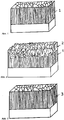
- Fig.1 is a sketch of a typical layer morphology for a molybdenum nitride layer MoN produced by reactive spark evaporation.
- the molybdenum nitride layer MoN was deposited by the inventors on an adhesion layer of chromium nitride CrN (thickness of the adhesion layer about 300 nm).
- the MoN layer was produced at a temperature of 450 ° C with a Mo target and a spark current of 220 A.
- the nitrogen pressure was 3.5 Pa and a substrate bias of 20 V was used.
- the coefficients of friction of the deposited layers were also determined.
- an SRV test or a tribometer from the company Optimol Instruments fürtechnik GmbH was used.
- the two test specimens installed in the test chamber (one ball on a disk) were pressed together with a given normal force.
- the upper specimen in this case the counterbody (an uncoated 100Cr6 steel ball) oscillated on the lower specimen (the coated specimen disc).
- Frequency, glide path, test load, test temperature and test duration were specified for the measurement.
- the friction forces were continuously recorded by a sensor and thus the coefficients of friction could be calculated automatically. The wear on both specimens during the measurement was also evaluated after the measurement.
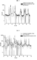
- the XRD spectrum in Fig.4 shows the typical Bragg reflections for the MoN produced by spark evaporation.
- Fig. 2 the sketch of a layer of Mo-NO deposited on a CrN adhesive layer is shown.
- the Mo-NO layer was fabricated on an approximately 300 nm CrN subbing layer, under similar conditions as the MoN layers described above, at 450 ° C substrate temperature and a spark current of 220A. After a short period of a few minutes in pure nitrogen, oxygen was added to the process controlled to the nitrogen pressure of 3.5 Pa, whereby the oxygen flow was gradually or linearly increased from 50 sccm to 800 sccm over about 2 hours.
- the SEM fracture cross section shows a clear transition to a loose layer structure in the last third of the layer (as in Fig. 2 was sketched).
- the upper layer showed the loosely deposited MoO 3 layer, which has lubricating properties but hardly any mechanical strength.
- the layer termination is intentionally carried out with a high oxygen flux, so that it comes to the formation of molybdenum trioxide (MoO 3 ) at the layer surface and thus a soft inlet layer is produced, for example MoO 3 on MoO.
- MoO 3 molybdenum trioxide
- Fig. 5 shows the XRD spectrum generated by X-ray diffraction analysis (XRD) in Fig. 2 recorded Mo-ON layer.
- XRD X-ray diffraction analysis
- Fig. 3 The SEM layer cross-section of a prepared controlled oxygen layer was outlined.
- the layer showed a morphology distinctly different from that of the layer deposited in Fig.2 outlined.
- the morphology of the manufactured layer with controlled Oxygen content is similar to that of MoN, although more than 5 at.% Oxygen is detectable in the layer with EDX.
- MoO molybdenum monoxide
- the proportion z - (d + y) of Mo then corresponds to the non-reacted with nitrogen and / or oxygen molybdenum. This then occurs, for example, in the case of spark evaporation in the form of conglomerates incorporated into the layer, which are the result of incompletely fully reacted molybdenum and are known in the art as droplets.
- the layer in Fig. 3 was sketched, was deposited without adhesive layer.
- 2 molybdenum targets were used, both operated with 220 A spark current.
- the coating process was controlled to a constant total pressure of 4 Pa, which was initially created by introducing nitrogen into the coating chamber.
- the process parameters were varied alternately and continuously during the entire deposition process by adding an oxygen flow of 50 sccm to the regulated total pressure for 40 s in each case and then again interrupting the oxygen flow for 3 min until the entire layer thickness was reached.
- EDX Energy-dispersive X-ray microsphere analysis
- the Mo-O layers produced by the sputtering can be controlled by the oxygen flux so that the stable and ductile MoO (molybdenum monoxide) can be prepared and incorporated into a MoN matrix or synthesized as a single layer ,
- MoO 3 without or with very little incorporation of the abrasive MoO 2 in the layer, can be realized in a fast oxide ramp and thus the production of a solid surface lubrication in the same process is possible.
- an outer MoO 3 layer produced in this way is particularly suitable as a running-in layer.
- MoO layers can also be incorporated into any desired layer.
- the MoO layers and MoO + MoO 3 layers, wherein MoO 3 is used as the run-in layer, are in particular incorporated as outer layers, in order to be able to set a certain softness or an improved run-in behavior compared to the original layer system, thus, for example, the wear of the counter bodies a tribological system is minimized and at the same time a stabilized oxidation behavior of Mo-containing layers is present.
- MoO in any layer and especially in other oxide layers, e.g. Al-O, CrO, Zr-O, Ti-O and / or also in mixed oxide layers, e.g. (Al, Cr) O, (Zr, Cr) O or Cr-O by e.g. Adjust suppleness.
- Similar layer systems can also be produced with alloyed targets of Mo in combination with other metals, or by activating targets of other metals and / or alloys and / or other materials during the coating process in addition to the Mo target or the Mo targets. evaporates.
- layer systems which comprise carbides. These layer systems are also introduced by means of spark evaporation and / or pulsed spark evaporation by additionally introducing a carbon-containing gas during the coating and / or by activating or evaporating carbon targets and / or carbon-containing targets
- the transition between first and second layer may be formed gradually.
- a significant improvement in toughness is achieved by the deposition of multilayer coatings. At the same time, crack propagation from the surface to the base material is prevented in this way. Furthermore, in many cases, the maximum layer thickness can be increased, since mechanical stresses in the layer can be reduced in comparison with the monolayer layer with the multilayer composite layer.
- an adaptation of the material properties of the various layers is appropriate required. This can be achieved, for example, by the creation of graded boundary / transition layers or by the deposition of intermediate layers.
- Example 1 It is generally advantageous that piston rings and shaft sealing rings have good mechanical stability and at the same time good lubricant properties and / or suppleness.
- a stainless steel piston ring was sputter-coated with Mo-N.
- the piston ring is placed in the coating chamber of a coating system.
- the coating chamber is evacuated and, to clean / activate the surface, the surface is heated and etched prior to coating.
- a spark is ignited in the nitrogen atmosphere on a molybdenum target serving as a cathode, resulting in the evaporation of molybdenum and / or already reacted molybdenum nitrite.
- Depositing the material on the piston surface results in the formation of a 2 ⁇ m thick Mo-N layer.
- the coating process allows the application-specific adaptation of the layer thickness.
- the growth of various phases of Mo-N can be very well regulated by setting various pulse parameters when applying a pulsed bias voltage and / or operating a pulsed radio-frequency source. This makes it possible that by a certain adjustment of the coating parameters, in particular the pulse parameters, the growth of a particular phase is favored and Mo-N layers with special properties, adapted to the use of the coated component, can be produced. It is also possible, by varying the coating parameters during coating, to build up multilayered Mo-N layers with different phases, for example alternately. In particular, a layer system can thus be constructed in which cubic Mo-N alternate with hexagonal Mo-N. Such a layer system comprising at least two layers then comprises at least one inner cubic and therefore hard layer and an outer hexagonal and therefore softer layer.
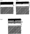
- a two-layered layer system is applied to the functional surface or to the substrate 1: the first layer is then a Mo-N layer 5 and the second layer a molybdenum monoxide layer 9 as in Figure 7a shown.
- an additional adhesive layer may be provided, as in FIG. 7b shown.
- the adhesive layer 3 is provided between the substrate 1 and the first layer 5 in the layer system.
- the adhesive layer may be both a pure metal layer (such as Cr, Mo, Ti, Si) or a composite (such as Me-N or Me-NC), where Me is also a combination of metals possible.
- the transition between the first layer 5 and the second layer 9 may be formed as a gradient, such that as the distance from the surface of the substrate increases, the Mo-N concentration decreases and at the same time the Mo-O concentration increases. This leads to a very good adhesion within the layer system.
- the gradient may include the whole layer and / or the whole layers.
- a further improvement in toughness in the layer system may be due to the deposition of several nanolagic layers, or by the production of nanocomposite structures in which, for example, the harder phase is embedded in the form of nanospheres in a matrix of the softer phase.
- X-layer is used in the context of the present description when the layer predominantly contains X, where X may be an elementary substance or a compound.
- a coating which comprises at least one molybdenum-containing layer with molybdenum oxide and which is characterized in that the molybdenum oxide is essentially molybdenum monoxide.
- the coating may include, for example, a molybdenum oxide layer comprising substantially molybdenum monoxide.
- a layer of MoO layer can be differentiated from MoO 2 and MoO 3 layers by, for example, the XRD spectrum of the molybdenum monoxide layer (MoO) having essentially neither MoO 2 peaks nor MoO 3 peaks.
- a preferred variant of the coating may, for example, additionally comprise a molybdenum nitride layer.
- the coating according to the invention also contains a Mo-NO layer which comprises molybdenum nitrogen bonds and molybdenum oxide bonds, with essentially the molybdenum atoms having at most one oxygen atom Forming compound and in the coating is preferably contained molybdenum monoxide.
- a preferred variant of the coating according to the invention with at least one Mo-N-O layer is characterized in that the Mo-N-O layer lies between a molybdenum nitride layer and a molybdenum monoxide layer.
- the Mo-N-O layer may also be a graded layer, with the nitrogen concentration decreasing from the substrate-near interface to the near-surface interface of the Mo-N-O layer as the oxygen concentration increases.
- the Mo-N-O layer may be a graded layer wherein the oxygen concentration decreases from the substrate-near interface to the near-surface interface of the Mo-N-O layer while the nitrogen concentration increases.
- a coating may also be deposited as a multi-layered system, with multiple MoN and MoO layers deposited alternately, and may also be e.g. contain several Mo-N-O layers, e.g. lie between the MoN and MoO layers and which can be deposited as graded layers with adapted variations of the nitrogen and oxygen concentrations to improve the adhesion within the layer.
- the coating according to the invention can also additionally have a covering layer with MoO 3 , if the MoO 3 can bring about further advantages related to the application.
- the coating between the base body and the Mo-containing layer may also comprise one or more adhesive layer (s) and / or functional layer (s).
- a preferred variant of the method for producing the coating is a PVD method or combined PVD / CVD method, wherein the molybdenum monoxide is deposited in the layer comprising molybdenum monoxide by means of spark evaporation.
- a further preferred variant of the method for producing the coating is a PVD method, wherein the molybdenum-containing layers are produced by spark evaporation of at least the molybdenum-containing layers by means of spark evaporation of at least one molybdenum-containing target in a reactive atmosphere.
- both molybdenum targets and alloyed molybdenum-containing targets can be used, which can be produced, for example, by melt metallurgy or powder metallurgy.
- Components can be coated with the application of the more suitable variant of the coating according to the invention.
- cutting tools and forming tools which are coated according to the invention for the production of components made of metals or metal alloys, in order to reduce or preferably completely avoid lube deposits of the processed metals or metal alloys on the coated surface of the tool.
- Fig. 1 Sketching of the layer morphology of a MoN sputtered vapor deposition layer with CrN adhesion layer in the SEM fracture cross section.
- Fig. 2 Sketching of the layer morphology of a sputtered Mo-N / Mo-NO / Mo-O layer with CrN adhesion layer in the SEM fracture cross-section, wherein the molybdenum oxide phases MoO 2 and MoO 3 are detectable in the layer by XRD.
- Fig. 3 Delineation of the layer morphology of a Mo-N produced by arc vaporization / Mo-NO / MoO layer without the adhesive layer in the SEM the rupture cross-section, with no Molybdänoxidphasen MoO 2 and MoO 3 in the layer detectable by XRD, though more than 10 atomic percent oxygen in the Layer is detectable by EDX.
- the layer was prepared by timed addition of an oxygen flux of 50 sccm (pressure controlled at 4 Pa) with an on time of 40 s and an off time of 3 min.
- Fig. 4 Typical XRD spectrum of a MoN layer whose Bragg reflections are in accordance with the MoN reference ISDN 00-025-1367.
- Fig. 5 Typical XRD spectrum of a MoO 3 layer whose Bragg reflections are in accordance with the MoO 3 reference ISDN 00-001-0706.
- Fig. 6 Typical XRD spectrum of a molybdenum monoxide layer.
Landscapes
- Chemical & Material Sciences (AREA)
- Engineering & Computer Science (AREA)
- Organic Chemistry (AREA)
- Chemical Kinetics & Catalysis (AREA)
- Materials Engineering (AREA)
- Mechanical Engineering (AREA)
- Metallurgy (AREA)
- Inorganic Chemistry (AREA)
- Ceramic Engineering (AREA)
- General Chemical & Material Sciences (AREA)
- Oil, Petroleum & Natural Gas (AREA)
- Physical Vapour Deposition (AREA)
- Lubricants (AREA)
- Laminated Bodies (AREA)
- Inorganic Compounds Of Heavy Metals (AREA)
- Coating By Spraying Or Casting (AREA)
- Drilling Tools (AREA)
- Cutting Tools, Boring Holders, And Turrets (AREA)
Applications Claiming Priority (3)
| Application Number | Priority Date | Filing Date | Title |
|---|---|---|---|
| US40765610P | 2010-10-28 | 2010-10-28 | |
| DE102010053751A DE102010053751A1 (de) | 2010-10-28 | 2010-12-08 | Molybdänmonoxidschichten und deren Herstellung mittels PVD |
| PCT/EP2011/004990 WO2012055485A1 (de) | 2010-10-28 | 2011-10-06 | Molybdänmonoxidschichten und deren herstellung mittels pvd |
Publications (2)
| Publication Number | Publication Date |
|---|---|
| EP2633095A1 EP2633095A1 (de) | 2013-09-04 |
| EP2633095B1 true EP2633095B1 (de) | 2017-09-13 |
Family
ID=45935681
Family Applications (1)
| Application Number | Title | Priority Date | Filing Date |
|---|---|---|---|
| EP11779086.5A Not-in-force EP2633095B1 (de) | 2010-10-28 | 2011-10-06 | Molybdänmonoxidschichten und deren herstellung mittels pvd |
Country Status (13)
| Country | Link |
|---|---|
| US (1) | US9822322B2 (enExample) |
| EP (1) | EP2633095B1 (enExample) |
| JP (2) | JP2013545893A (enExample) |
| KR (1) | KR101930564B1 (enExample) |
| CN (1) | CN103270188B (enExample) |
| BR (1) | BR112013010147A2 (enExample) |
| CA (1) | CA2815911A1 (enExample) |
| DE (1) | DE102010053751A1 (enExample) |
| MX (1) | MX350887B (enExample) |
| MY (1) | MY179397A (enExample) |
| RU (1) | RU2622553C2 (enExample) |
| SG (1) | SG190021A1 (enExample) |
| WO (1) | WO2012055485A1 (enExample) |
Families Citing this family (22)
| Publication number | Priority date | Publication date | Assignee | Title |
|---|---|---|---|---|
| DE102012200378A1 (de) * | 2012-01-12 | 2013-07-18 | Federal-Mogul Burscheid Gmbh | Kolbenring |
| WO2013135364A2 (en) | 2012-03-12 | 2013-09-19 | Oerlikon Trading Ag, Trübbach | Coating with enhanced sliding properties |
| DE102012207814A1 (de) * | 2012-05-10 | 2013-11-14 | Mahle International Gmbh | Bauelement, insbesondere ein Gleitelement |
| DE102012207813A1 (de) * | 2012-05-10 | 2013-11-14 | Mahle International Gmbh | Gleitkörper mit Beschichtung |
| DE102012017033A1 (de) * | 2012-08-29 | 2014-05-28 | Oerlikon Trading Ag, Trübbach | PVD Lichtbogenbeschichtung mit verbesserten reibungsmindernden und verschleissreduzierenden Eigenschaften |
| BR112015004486A2 (pt) * | 2012-08-29 | 2017-07-04 | Oerlikon Surface Solutions Ag Truebbach | revestimento de pvd de arco com propriedades intensificadas de redução de fricção e redução de desgaste |
| AR092945A1 (es) * | 2012-10-10 | 2015-05-06 | Oerlikon Trading Ag Trübbach | Recubrimiento para usos a altas temperaturas con solicitacion tribologica |
| DE102012023260A1 (de) * | 2012-11-29 | 2014-06-05 | Oerlikon Trading Ag, Trübbach | Verfahren zur Strukturierung von Schichtoberflächen und Vorrichtung dazu |
| CN104372299B (zh) * | 2013-09-23 | 2017-08-04 | 中国科学院合肥物质科学研究院 | 多层结构硬质、耐磨、润滑涂层及其制备方法 |
| DE102013018007A1 (de) | 2013-11-29 | 2015-06-03 | Oerlikon Trading Ag, Trübbach | Verfahren zur Verbesserung des Gegenkörperverschleisses im tribologischen Kontakt |
| CN103789725B (zh) * | 2014-01-29 | 2016-08-31 | 仪征亚新科双环活塞环有限公司 | 一种活塞环表面的多层多元复合硬质pvd镀层、活塞环及制备工艺 |
| WO2016012600A1 (en) * | 2014-07-24 | 2016-01-28 | Oerlikon Surface Solutions Ag, Trübbach | Arc evaporated me11-ame2azi/mo1-b-csicbbzii multilayer coatings |
| KR101673712B1 (ko) * | 2014-12-10 | 2016-11-08 | 현대자동차주식회사 | 자동차 습동 부품용 코팅재 및 이를 이용한 자동차 습동부품 표면처리 방법 |
| CN108048809B (zh) * | 2017-09-22 | 2019-07-30 | 南京航空航天大学 | 耐蚀抗菌的含银MoO3-SiO2纳米晶复合涂层的制备方法 |
| US11149651B2 (en) * | 2019-08-07 | 2021-10-19 | Raytheon Technologies Corporation | Seal ring assembly for a gas turbine engine |
| EP4031690A1 (de) * | 2019-09-19 | 2022-07-27 | Oerlikon Surface Solutions AG, Pfäffikon | Substrat mit einem molydännitrid schichtsystem, sowie beschichtungsverfahren zur herstellung eines schichtsystems |
| WO2022112605A1 (en) * | 2020-11-30 | 2022-06-02 | Oerlikon Surface Solutions Ag, Pfäffikon | Molybdenum nitride based multilayer coating for wear and friction reduction |
| CN114583055B (zh) * | 2022-02-18 | 2023-09-15 | 电子科技大学 | 一种喷涂MoO3薄膜的有机光电探测器及其制备方法 |
| CN114907900B (zh) * | 2022-05-31 | 2023-07-21 | 东莞市嘉丰润滑科技有限公司 | 一种自动变速箱油、i类金属切削液和新型润滑油 |
| JP7812758B2 (ja) | 2022-07-29 | 2026-02-10 | 株式会社Screenホールディングス | 基板処理方法および基板処理装置 |
| JP7837241B2 (ja) * | 2022-07-29 | 2026-03-30 | 株式会社Screenホールディングス | 基板処理方法および基板処理装置 |
| CN117488301B (zh) * | 2023-10-31 | 2025-10-24 | 深圳技术大学 | 一种金属表面的蜂窝状复合氧化钼涂层及其制备方法和在油水分离中的应用 |
Citations (1)
| Publication number | Priority date | Publication date | Assignee | Title |
|---|---|---|---|---|
| US20100167463A1 (en) * | 2008-12-29 | 2010-07-01 | Min-Gyu Sung | Method for Fabricating Resistive Memory Device |
Family Cites Families (27)
| Publication number | Priority date | Publication date | Assignee | Title |
|---|---|---|---|---|
| US4847171A (en) * | 1988-03-10 | 1989-07-11 | Ford Motor Company | Molybdenum oxide electrodes for thermoelectric generators |
| SU1832751A1 (ru) | 1990-06-18 | 1998-01-20 | Научно-производственное объединение "НИИТавтопром" | Способ получения износостойких покрытий из соединений металлов |
| EP0617199B1 (de) * | 1993-03-26 | 1996-01-31 | Siemens Aktiengesellschaft | Katalysator zur Stickoxidminderung im Abgas eines Verbrennungsmotors |
| DK16494A (da) | 1994-02-08 | 1995-08-09 | Man B & W Diesel Gmbh | Fremgangsmåde til fremstilling af en cylinderforing samt en sådan foring |
| JP3452664B2 (ja) * | 1994-11-21 | 2003-09-29 | 帝国ピストンリング株式会社 | 摺動部材およびその製造方法 |
| JP3286097B2 (ja) * | 1994-12-22 | 2002-05-27 | 帝国ピストンリング株式会社 | 摺動部材およびその製造方法 |
| DE29620687U1 (de) | 1996-11-28 | 1997-01-30 | Fehling, Ulrike, 63791 Karlstein | Chirurgisches Instrument |
| JP3439949B2 (ja) * | 1997-06-09 | 2003-08-25 | 帝国ピストンリング株式会社 | 硬質被覆材およびそれを被覆した摺動部材ならびにその製造方法 |
| US6802457B1 (en) | 1998-09-21 | 2004-10-12 | Caterpillar Inc | Coatings for use in fuel system components |
| RU12540U1 (ru) * | 1999-07-02 | 2000-01-20 | Открытое акционерное общество "ГАЗ" | Устройство для электроискрового легирования металлических поверхностей |
| US6537613B1 (en) * | 2000-04-10 | 2003-03-25 | Air Products And Chemicals, Inc. | Process for metal metalloid oxides and nitrides with compositional gradients |
| US7311961B2 (en) * | 2000-10-24 | 2007-12-25 | Ppg Industries Ohio, Inc. | Method of making coated articles and coated articles made thereby |
| RU2196665C1 (ru) * | 2001-09-10 | 2003-01-20 | Открытое акционерное общество "Иркутское авиационное производственное объединение" | Способ электроискрового легирования |
| RU2211260C1 (ru) * | 2001-12-26 | 2003-08-27 | Федеральное государственное унитарное предприятие Всероссийский научно-исследовательский институт авиационных материалов | Антифрикционное композиционное покрытие |
| US7344806B2 (en) * | 2003-03-31 | 2008-03-18 | Shin-Etsu Chemical Co., Ltd. | Method of producing phase shift mask blank, method of producing phase shift mask, phase shift mask blank, and phase shift mask |
| US20060042728A1 (en) | 2004-08-31 | 2006-03-02 | Brad Lemon | Molybdenum sputtering targets |
| US7332618B2 (en) * | 2004-09-28 | 2008-02-19 | Praxair Technology, Inc. | Organometallic precursor compounds |
| US7950271B2 (en) | 2005-03-18 | 2011-05-31 | Applied Nanotech Holdings, Inc. | Gated beta-molybdenum oxide sensor |
| CA2599374A1 (en) * | 2005-03-18 | 2006-09-28 | Nano-Proprietary, Inc. | Gated gas sensor |
| EP2355126B1 (de) * | 2005-03-24 | 2015-12-02 | Oerlikon Surface Solutions AG, Trübbach | Hartstoffschicht |
| KR100655366B1 (ko) * | 2005-07-04 | 2006-12-08 | 한국과학기술연구원 | 내열, 내마모, 저마찰 특성을 가지는 코팅제 및 이의코팅방법 |
| DE102006036101A1 (de) | 2005-08-02 | 2007-02-08 | Caterpillar Motoren Gmbh & Co. Kg | Verfahren zur Herstellung von Ventilkomponenten |
| JP4824989B2 (ja) | 2005-11-02 | 2011-11-30 | 株式会社神戸製鋼所 | 硬質皮膜 |
| JP2006255708A (ja) | 2006-07-05 | 2006-09-28 | Mitsubishi Heavy Ind Ltd | 中空糸膜の逆洗方法及び中空糸膜水処理装置 |
| US20090087673A1 (en) | 2007-09-28 | 2009-04-02 | Taylor Steven C | Method for coating fuel system components |
| EP2166128B1 (de) * | 2008-09-19 | 2011-11-09 | Oerlikon Trading AG, Trübbach | Verfahren zum Herstellen von Metalloxidschichten durch Funkenverdampfung |
| RU2501885C2 (ru) * | 2008-08-17 | 2013-12-20 | Эрликон Трейдинг Аг, Трюббах | Применение мишени для искрового напыления и способ получения подходящей для этого применения мишени |
-
2010
- 2010-12-08 DE DE102010053751A patent/DE102010053751A1/de not_active Withdrawn
-
2011
- 2011-10-06 CA CA2815911A patent/CA2815911A1/en not_active Abandoned
- 2011-10-06 JP JP2013535294A patent/JP2013545893A/ja active Pending
- 2011-10-06 CN CN201180063789.XA patent/CN103270188B/zh not_active Expired - Fee Related
- 2011-10-06 MX MX2013004780A patent/MX350887B/es active IP Right Grant
- 2011-10-06 US US13/881,855 patent/US9822322B2/en not_active Expired - Fee Related
- 2011-10-06 EP EP11779086.5A patent/EP2633095B1/de not_active Not-in-force
- 2011-10-06 RU RU2013124399A patent/RU2622553C2/ru not_active IP Right Cessation
- 2011-10-06 KR KR1020137013593A patent/KR101930564B1/ko not_active Expired - Fee Related
- 2011-10-06 SG SG2013032081A patent/SG190021A1/en unknown
- 2011-10-06 MY MYPI2013001508A patent/MY179397A/en unknown
- 2011-10-06 BR BR112013010147A patent/BR112013010147A2/pt active Search and Examination
- 2011-10-06 WO PCT/EP2011/004990 patent/WO2012055485A1/de not_active Ceased
-
2017
- 2017-09-05 JP JP2017170564A patent/JP2018035442A/ja active Pending
Patent Citations (1)
| Publication number | Priority date | Publication date | Assignee | Title |
|---|---|---|---|---|
| US20100167463A1 (en) * | 2008-12-29 | 2010-07-01 | Min-Gyu Sung | Method for Fabricating Resistive Memory Device |
Also Published As
| Publication number | Publication date |
|---|---|
| US9822322B2 (en) | 2017-11-21 |
| KR101930564B1 (ko) | 2019-03-11 |
| US20130303414A1 (en) | 2013-11-14 |
| RU2013124399A (ru) | 2014-12-10 |
| KR20140066967A (ko) | 2014-06-03 |
| EP2633095A1 (de) | 2013-09-04 |
| JP2013545893A (ja) | 2013-12-26 |
| JP2018035442A (ja) | 2018-03-08 |
| RU2622553C2 (ru) | 2017-06-16 |
| SG190021A1 (en) | 2013-06-28 |
| BR112013010147A2 (pt) | 2016-09-06 |
| WO2012055485A1 (de) | 2012-05-03 |
| CA2815911A1 (en) | 2012-05-03 |
| DE102010053751A1 (de) | 2012-05-03 |
| CN103270188A (zh) | 2013-08-28 |
| MX2013004780A (es) | 2013-12-16 |
| MX350887B (es) | 2017-09-22 |
| CN103270188B (zh) | 2016-03-16 |
| MY179397A (en) | 2020-11-05 |
Similar Documents
| Publication | Publication Date | Title |
|---|---|---|
| EP2633095B1 (de) | Molybdänmonoxidschichten und deren herstellung mittels pvd | |
| DE102005063537B4 (de) | Hartstoff - Schichtsystem | |
| EP1161572B1 (de) | Schneideinsatz zum zerspanen von metallischen werkstoffen mit einer molybdänsulfid enthaltenden beschichtung und verfahren zu dessen herstellung | |
| EP0513662B1 (de) | Verfahren zum Beschichten des Werkstückes und mit einer Hartschicht versehener Grundkörper | |
| DE60124061T2 (de) | Hartstoffschicht für Schneidwerkzeuge | |
| EP2166128B1 (de) | Verfahren zum Herstellen von Metalloxidschichten durch Funkenverdampfung | |
| EP1120473B1 (de) | Zerspanungswerkzeug mit Carbonitrid-Beschichtung | |
| EP1627094A2 (de) | Werkstück mit alcr-haltiger hartstoffschicht und verfahren zur herstellung | |
| EP1783245B1 (de) | Werkzeug oder verschleissteil sowie ein pvd-beschichtungsverfahren zum aufbringen einer oberflächenschicht auf einem werkzeug oder verschleissteil | |
| EP2912206B1 (de) | Bauteil mit einer beschichtung und verfahren zu seiner herstellung | |
| AT8346U1 (de) | Beschichtetes werkzeug | |
| EP2912207B1 (de) | Bauteil mit einer beschichtung und verfahren zu seiner herstellung | |
| EP3929325A1 (de) | Verfahren zur herstellung einer beschichtungsquelle zur physikalischen gasphasenabscheidung von crtan, sowie dadurch hergestellte crta beschichtungsquelle | |
| DE102016122834A1 (de) | Beschichtung eines Körpers mit Diamantschicht und Hartstoffschicht | |
| DE19957671A1 (de) | Werkzeug mit einer Molybdänsulfid enthaltenden Beschichtung und Verfahren zu dessen Herstellung | |
| DE102012007796A1 (de) | Beschichtung enthaltend Si-DLC, DLC und Me-DLC und Verfahren zur Herstellung von Beschichtungen | |
| WO2013086552A1 (de) | Kohlenstoffbasierende beschichtung | |
| DE112014005504T5 (de) | Kolbenring | |
| EP2369031B1 (de) | Beschichtung auf nial2o4 basis in spinellstruktur | |
| EP2179073B1 (de) | Al-Ti-Ru-N-C HARTSTOFFSCHICHT | |
| DE112018004793B4 (de) | Target zur physikalischen gasphasenabscheidung, nanokomposit- beschichtungsfilm unter verwendung desselben, und herstellungsverfahren dafür | |
| EP2925901B1 (de) | Verfahren zur strukturierung von schichtoberflächen und beschichtestes substrat | |
| EP1413647B1 (de) | Verschleissschutzschicht | |
| DE112008001939B4 (de) | Oxidfilm, Oxidfilm-beschichtetes Material und Verfahren zum Bilden eines Oxidfilms |
Legal Events
| Date | Code | Title | Description |
|---|---|---|---|
| PUAI | Public reference made under article 153(3) epc to a published international application that has entered the european phase |
Free format text: ORIGINAL CODE: 0009012 |
|
| 17P | Request for examination filed |
Effective date: 20130528 |
|
| AK | Designated contracting states |
Kind code of ref document: A1 Designated state(s): AL AT BE BG CH CY CZ DE DK EE ES FI FR GB GR HR HU IE IS IT LI LT LU LV MC MK MT NL NO PL PT RO RS SE SI SK SM TR |
|
| DAX | Request for extension of the european patent (deleted) | ||
| RAP1 | Party data changed (applicant data changed or rights of an application transferred) |
Owner name: OERLIKON SURFACE SOLUTIONS AG, TRUEBBACH |
|
| 17Q | First examination report despatched |
Effective date: 20160502 |
|
| REG | Reference to a national code |
Ref country code: DE Ref legal event code: R079 Ref document number: 502011012996 Country of ref document: DE Free format text: PREVIOUS MAIN CLASS: C23C0014000000 Ipc: C23C0028000000 |
|
| RIC1 | Information provided on ipc code assigned before grant |
Ipc: C23C 14/34 20060101ALI20170407BHEP Ipc: C23C 14/06 20060101ALI20170407BHEP Ipc: C23C 14/08 20060101ALI20170407BHEP Ipc: C23C 14/32 20060101ALI20170407BHEP Ipc: C23C 14/02 20060101ALI20170407BHEP Ipc: C23C 28/04 20060101ALI20170407BHEP Ipc: C23C 14/00 20060101ALI20170407BHEP Ipc: C23C 14/54 20060101ALI20170407BHEP Ipc: C23C 28/00 20060101AFI20170407BHEP |
|
| GRAP | Despatch of communication of intention to grant a patent |
Free format text: ORIGINAL CODE: EPIDOSNIGR1 |
|
| STAA | Information on the status of an ep patent application or granted ep patent |
Free format text: STATUS: GRANT OF PATENT IS INTENDED |
|
| INTG | Intention to grant announced |
Effective date: 20170607 |
|
| GRAS | Grant fee paid |
Free format text: ORIGINAL CODE: EPIDOSNIGR3 |
|
| GRAA | (expected) grant |
Free format text: ORIGINAL CODE: 0009210 |
|
| STAA | Information on the status of an ep patent application or granted ep patent |
Free format text: STATUS: THE PATENT HAS BEEN GRANTED |
|
| RAP1 | Party data changed (applicant data changed or rights of an application transferred) |
Owner name: OERLIKON SURFACE SOLUTIONS AG, PFAEFFIKON |
|
| AK | Designated contracting states |
Kind code of ref document: B1 Designated state(s): AL AT BE BG CH CY CZ DE DK EE ES FI FR GB GR HR HU IE IS IT LI LT LU LV MC MK MT NL NO PL PT RO RS SE SI SK SM TR |
|
| REG | Reference to a national code |
Ref country code: GB Ref legal event code: FG4D Free format text: NOT ENGLISH |
|
| REG | Reference to a national code |
Ref country code: CH Ref legal event code: EP |
|
| REG | Reference to a national code |
Ref country code: IE Ref legal event code: FG4D Free format text: LANGUAGE OF EP DOCUMENT: GERMAN |
|
| REG | Reference to a national code |
Ref country code: AT Ref legal event code: REF Ref document number: 928217 Country of ref document: AT Kind code of ref document: T Effective date: 20171015 |
|
| REG | Reference to a national code |
Ref country code: DE Ref legal event code: R096 Ref document number: 502011012996 Country of ref document: DE |
|
| REG | Reference to a national code |
Ref country code: FR Ref legal event code: PLFP Year of fee payment: 7 |
|
| REG | Reference to a national code |
Ref country code: NL Ref legal event code: MP Effective date: 20170913 |
|
| REG | Reference to a national code |
Ref country code: LT Ref legal event code: MG4D |
|
| PG25 | Lapsed in a contracting state [announced via postgrant information from national office to epo] |
Ref country code: HR Free format text: LAPSE BECAUSE OF FAILURE TO SUBMIT A TRANSLATION OF THE DESCRIPTION OR TO PAY THE FEE WITHIN THE PRESCRIBED TIME-LIMIT Effective date: 20170913 Ref country code: NO Free format text: LAPSE BECAUSE OF FAILURE TO SUBMIT A TRANSLATION OF THE DESCRIPTION OR TO PAY THE FEE WITHIN THE PRESCRIBED TIME-LIMIT Effective date: 20171213 Ref country code: SE Free format text: LAPSE BECAUSE OF FAILURE TO SUBMIT A TRANSLATION OF THE DESCRIPTION OR TO PAY THE FEE WITHIN THE PRESCRIBED TIME-LIMIT Effective date: 20170913 Ref country code: FI Free format text: LAPSE BECAUSE OF FAILURE TO SUBMIT A TRANSLATION OF THE DESCRIPTION OR TO PAY THE FEE WITHIN THE PRESCRIBED TIME-LIMIT Effective date: 20170913 Ref country code: LT Free format text: LAPSE BECAUSE OF FAILURE TO SUBMIT A TRANSLATION OF THE DESCRIPTION OR TO PAY THE FEE WITHIN THE PRESCRIBED TIME-LIMIT Effective date: 20170913 |
|
| PG25 | Lapsed in a contracting state [announced via postgrant information from national office to epo] |
Ref country code: BG Free format text: LAPSE BECAUSE OF FAILURE TO SUBMIT A TRANSLATION OF THE DESCRIPTION OR TO PAY THE FEE WITHIN THE PRESCRIBED TIME-LIMIT Effective date: 20171213 Ref country code: RS Free format text: LAPSE BECAUSE OF FAILURE TO SUBMIT A TRANSLATION OF THE DESCRIPTION OR TO PAY THE FEE WITHIN THE PRESCRIBED TIME-LIMIT Effective date: 20170913 Ref country code: ES Free format text: LAPSE BECAUSE OF FAILURE TO SUBMIT A TRANSLATION OF THE DESCRIPTION OR TO PAY THE FEE WITHIN THE PRESCRIBED TIME-LIMIT Effective date: 20170913 Ref country code: GR Free format text: LAPSE BECAUSE OF FAILURE TO SUBMIT A TRANSLATION OF THE DESCRIPTION OR TO PAY THE FEE WITHIN THE PRESCRIBED TIME-LIMIT Effective date: 20171214 Ref country code: LV Free format text: LAPSE BECAUSE OF FAILURE TO SUBMIT A TRANSLATION OF THE DESCRIPTION OR TO PAY THE FEE WITHIN THE PRESCRIBED TIME-LIMIT Effective date: 20170913 |
|
| PG25 | Lapsed in a contracting state [announced via postgrant information from national office to epo] |
Ref country code: NL Free format text: LAPSE BECAUSE OF FAILURE TO SUBMIT A TRANSLATION OF THE DESCRIPTION OR TO PAY THE FEE WITHIN THE PRESCRIBED TIME-LIMIT Effective date: 20170913 |
|
| PG25 | Lapsed in a contracting state [announced via postgrant information from national office to epo] |
Ref country code: CZ Free format text: LAPSE BECAUSE OF FAILURE TO SUBMIT A TRANSLATION OF THE DESCRIPTION OR TO PAY THE FEE WITHIN THE PRESCRIBED TIME-LIMIT Effective date: 20170913 Ref country code: RO Free format text: LAPSE BECAUSE OF FAILURE TO SUBMIT A TRANSLATION OF THE DESCRIPTION OR TO PAY THE FEE WITHIN THE PRESCRIBED TIME-LIMIT Effective date: 20170913 Ref country code: PL Free format text: LAPSE BECAUSE OF FAILURE TO SUBMIT A TRANSLATION OF THE DESCRIPTION OR TO PAY THE FEE WITHIN THE PRESCRIBED TIME-LIMIT Effective date: 20170913 |
|
| PG25 | Lapsed in a contracting state [announced via postgrant information from national office to epo] |
Ref country code: SM Free format text: LAPSE BECAUSE OF FAILURE TO SUBMIT A TRANSLATION OF THE DESCRIPTION OR TO PAY THE FEE WITHIN THE PRESCRIBED TIME-LIMIT Effective date: 20170913 Ref country code: IS Free format text: LAPSE BECAUSE OF FAILURE TO SUBMIT A TRANSLATION OF THE DESCRIPTION OR TO PAY THE FEE WITHIN THE PRESCRIBED TIME-LIMIT Effective date: 20180113 Ref country code: IT Free format text: LAPSE BECAUSE OF FAILURE TO SUBMIT A TRANSLATION OF THE DESCRIPTION OR TO PAY THE FEE WITHIN THE PRESCRIBED TIME-LIMIT Effective date: 20170913 Ref country code: EE Free format text: LAPSE BECAUSE OF FAILURE TO SUBMIT A TRANSLATION OF THE DESCRIPTION OR TO PAY THE FEE WITHIN THE PRESCRIBED TIME-LIMIT Effective date: 20170913 Ref country code: SK Free format text: LAPSE BECAUSE OF FAILURE TO SUBMIT A TRANSLATION OF THE DESCRIPTION OR TO PAY THE FEE WITHIN THE PRESCRIBED TIME-LIMIT Effective date: 20170913 |
|
| REG | Reference to a national code |
Ref country code: DE Ref legal event code: R097 Ref document number: 502011012996 Country of ref document: DE |
|
| PG25 | Lapsed in a contracting state [announced via postgrant information from national office to epo] |
Ref country code: MC Free format text: LAPSE BECAUSE OF FAILURE TO SUBMIT A TRANSLATION OF THE DESCRIPTION OR TO PAY THE FEE WITHIN THE PRESCRIBED TIME-LIMIT Effective date: 20170913 |
|
| PLBE | No opposition filed within time limit |
Free format text: ORIGINAL CODE: 0009261 |
|
| STAA | Information on the status of an ep patent application or granted ep patent |
Free format text: STATUS: NO OPPOSITION FILED WITHIN TIME LIMIT |
|
| REG | Reference to a national code |
Ref country code: IE Ref legal event code: MM4A |
|
| PG25 | Lapsed in a contracting state [announced via postgrant information from national office to epo] |
Ref country code: LU Free format text: LAPSE BECAUSE OF NON-PAYMENT OF DUE FEES Effective date: 20171006 Ref country code: DK Free format text: LAPSE BECAUSE OF FAILURE TO SUBMIT A TRANSLATION OF THE DESCRIPTION OR TO PAY THE FEE WITHIN THE PRESCRIBED TIME-LIMIT Effective date: 20170913 |
|
| 26N | No opposition filed |
Effective date: 20180614 |
|
| REG | Reference to a national code |
Ref country code: BE Ref legal event code: MM Effective date: 20171031 |
|
| PG25 | Lapsed in a contracting state [announced via postgrant information from national office to epo] |
Ref country code: BE Free format text: LAPSE BECAUSE OF NON-PAYMENT OF DUE FEES Effective date: 20171031 |
|
| PG25 | Lapsed in a contracting state [announced via postgrant information from national office to epo] |
Ref country code: MT Free format text: LAPSE BECAUSE OF FAILURE TO SUBMIT A TRANSLATION OF THE DESCRIPTION OR TO PAY THE FEE WITHIN THE PRESCRIBED TIME-LIMIT Effective date: 20170913 |
|
| PG25 | Lapsed in a contracting state [announced via postgrant information from national office to epo] |
Ref country code: IE Free format text: LAPSE BECAUSE OF NON-PAYMENT OF DUE FEES Effective date: 20171006 |
|
| REG | Reference to a national code |
Ref country code: FR Ref legal event code: PLFP Year of fee payment: 8 |
|
| PG25 | Lapsed in a contracting state [announced via postgrant information from national office to epo] |
Ref country code: SI Free format text: LAPSE BECAUSE OF FAILURE TO SUBMIT A TRANSLATION OF THE DESCRIPTION OR TO PAY THE FEE WITHIN THE PRESCRIBED TIME-LIMIT Effective date: 20170913 |
|
| REG | Reference to a national code |
Ref country code: AT Ref legal event code: MM01 Ref document number: 928217 Country of ref document: AT Kind code of ref document: T Effective date: 20171006 |
|
| PG25 | Lapsed in a contracting state [announced via postgrant information from national office to epo] |
Ref country code: AT Free format text: LAPSE BECAUSE OF NON-PAYMENT OF DUE FEES Effective date: 20171006 |
|
| PGFP | Annual fee paid to national office [announced via postgrant information from national office to epo] |
Ref country code: DE Payment date: 20181031 Year of fee payment: 8 |
|
| PGFP | Annual fee paid to national office [announced via postgrant information from national office to epo] |
Ref country code: CH Payment date: 20181031 Year of fee payment: 8 Ref country code: FR Payment date: 20181031 Year of fee payment: 8 Ref country code: GB Payment date: 20181031 Year of fee payment: 8 |
|
| PG25 | Lapsed in a contracting state [announced via postgrant information from national office to epo] |
Ref country code: HU Free format text: LAPSE BECAUSE OF FAILURE TO SUBMIT A TRANSLATION OF THE DESCRIPTION OR TO PAY THE FEE WITHIN THE PRESCRIBED TIME-LIMIT; INVALID AB INITIO Effective date: 20111006 |
|
| PG25 | Lapsed in a contracting state [announced via postgrant information from national office to epo] |
Ref country code: CY Free format text: LAPSE BECAUSE OF NON-PAYMENT OF DUE FEES Effective date: 20170913 |
|
| PG25 | Lapsed in a contracting state [announced via postgrant information from national office to epo] |
Ref country code: MK Free format text: LAPSE BECAUSE OF FAILURE TO SUBMIT A TRANSLATION OF THE DESCRIPTION OR TO PAY THE FEE WITHIN THE PRESCRIBED TIME-LIMIT Effective date: 20170913 |
|
| PG25 | Lapsed in a contracting state [announced via postgrant information from national office to epo] |
Ref country code: TR Free format text: LAPSE BECAUSE OF FAILURE TO SUBMIT A TRANSLATION OF THE DESCRIPTION OR TO PAY THE FEE WITHIN THE PRESCRIBED TIME-LIMIT Effective date: 20170913 |
|
| REG | Reference to a national code |
Ref country code: DE Ref legal event code: R119 Ref document number: 502011012996 Country of ref document: DE |
|
| PG25 | Lapsed in a contracting state [announced via postgrant information from national office to epo] |
Ref country code: PT Free format text: LAPSE BECAUSE OF FAILURE TO SUBMIT A TRANSLATION OF THE DESCRIPTION OR TO PAY THE FEE WITHIN THE PRESCRIBED TIME-LIMIT Effective date: 20170913 |
|
| REG | Reference to a national code |
Ref country code: CH Ref legal event code: PL |
|
| PG25 | Lapsed in a contracting state [announced via postgrant information from national office to epo] |
Ref country code: DE Free format text: LAPSE BECAUSE OF NON-PAYMENT OF DUE FEES Effective date: 20200501 Ref country code: AL Free format text: LAPSE BECAUSE OF FAILURE TO SUBMIT A TRANSLATION OF THE DESCRIPTION OR TO PAY THE FEE WITHIN THE PRESCRIBED TIME-LIMIT Effective date: 20170913 Ref country code: CH Free format text: LAPSE BECAUSE OF NON-PAYMENT OF DUE FEES Effective date: 20191031 Ref country code: LI Free format text: LAPSE BECAUSE OF NON-PAYMENT OF DUE FEES Effective date: 20191031 |
|
| GBPC | Gb: european patent ceased through non-payment of renewal fee |
Effective date: 20191006 |
|
| PG25 | Lapsed in a contracting state [announced via postgrant information from national office to epo] |
Ref country code: GB Free format text: LAPSE BECAUSE OF NON-PAYMENT OF DUE FEES Effective date: 20191006 Ref country code: FR Free format text: LAPSE BECAUSE OF NON-PAYMENT OF DUE FEES Effective date: 20191031 |