EP2632672B1 - A structure for presses, in particular for forming ceramic products - Google Patents
A structure for presses, in particular for forming ceramic products Download PDFInfo
- Publication number
- EP2632672B1 EP2632672B1 EP11776895.2A EP11776895A EP2632672B1 EP 2632672 B1 EP2632672 B1 EP 2632672B1 EP 11776895 A EP11776895 A EP 11776895A EP 2632672 B1 EP2632672 B1 EP 2632672B1
- Authority
- EP
- European Patent Office
- Prior art keywords
- tract
- full
- presses
- arch
- reciprocally
- Prior art date
- Legal status (The legal status is an assumption and is not a legal conclusion. Google has not performed a legal analysis and makes no representation as to the accuracy of the status listed.)
- Active
Links
Images
Classifications
-
- B—PERFORMING OPERATIONS; TRANSPORTING
- B28—WORKING CEMENT, CLAY, OR STONE
- B28B—SHAPING CLAY OR OTHER CERAMIC COMPOSITIONS; SHAPING SLAG; SHAPING MIXTURES CONTAINING CEMENTITIOUS MATERIAL, e.g. PLASTER
- B28B3/00—Producing shaped articles from the material by using presses; Presses specially adapted therefor
- B28B3/02—Producing shaped articles from the material by using presses; Presses specially adapted therefor wherein a ram exerts pressure on the material in a moulding space; Ram heads of special form
-
- B—PERFORMING OPERATIONS; TRANSPORTING
- B30—PRESSES
- B30B—PRESSES IN GENERAL
- B30B15/00—Details of, or accessories for, presses; Auxiliary measures in connection with pressing
- B30B15/04—Frames; Guides
- B30B15/048—Laminated frame structures
-
- B—PERFORMING OPERATIONS; TRANSPORTING
- B30—PRESSES
- B30B—PRESSES IN GENERAL
- B30B5/00—Presses characterised by the use of pressing means other than those mentioned in the preceding groups
- B30B5/04—Presses characterised by the use of pressing means other than those mentioned in the preceding groups wherein the pressing means is in the form of an endless band
Definitions
- the invention relates to a structure for presses, in particular for forming ceramic products, in accordance with the preamble of claim 1.
- the field of use of the invention is very general and certainly comprises all possible applications in which a plastic forming or deforming by pressing with a preferably vertical direction of application of the force has to be carried out.
- the height of these structures is substantially due to the usual constructional technique which comprises use of a base and an upper crossbar, connected by the uprights or columns, which must be of considerable thickness - in the vertical direction - in order to guarantee the two planes supporting the reactions deriving from the application of the pressing force an accentuated undeformability: these are in fact the planes on which the lower and upper parts of the die act.
- the structure can reach heights of greater than 7 metres, of which about a third is interred.
- the present invention is directed principally to a considerable improvement of the characteristics or resistance to fatigue of the known applications. With this, the invention is aimed at guaranteeing a working life of the resistant elements of the presses that is in line with the working life expected for the plants in which the presses themselves are inserted. Further, some of the realisations actuated in conformity with the inventions of the cited publications are characterised by a relatively complicated construction, mainly caused by the components to be assembled.
- the main aim of the present invention is to obviate the limitations in the prior art, by disclosing a compact, light and simple press in terms of constitution and assembly, which is structured in line with a modular concept.
- An advantage of the invention consists in the fact of presenting a structure which, given an equal maximum-applicable compression force, is characterised by considerable lightness and a very contained overall size.
- a further advantage of the invention consists in being constructionally very simple in general, in particular as far as the structure of the resistant elements or arches are concerned, as well as in relation to the number of components and the assembly mode thereof.
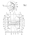
- 1 denotes in its entirety a resistant element 1 which, in turn, is constituted by a monolithic annular element or arch 2, which is flat, as it is fashioned with a suitable profiling from a large-thickness sheet.
- the internal space of the annular element or arch 2 is in part delimited by two facing surfaces 20 which are located in diametrically opposite positions and between which at least a power organ 5 can be inserted, which power organ 5 is destined to exert the pressing action by compressing, between two bodies, the object or the material to be pressed such as to unload on the facing and parallel surfaces 20 the equal and opposite reactions of the pressing action. Normally these reactions unload between the facing surfaces 20 of a plurality of resistant elements 1 that are consecutively arranged such as to form the overall structure of the press (see figures 2 and 3 ).
- annular element or arch 2 is fashioned from a single slab or single sheet, normally made of steel, which is appropriately cut to a precise shape which is symmetrical at least with respect to a vertical median plane of which the axis X-X represents a trace.
- each annular element or arch 2 includes full-thickness cuts 3 starting from the ends of the facing surfaces 20.
- Each full-thickness cut 3 exhibits a predetermined width and, starting from the corresponding end of the relative facing surface 20, develops over a polycentrically-curved arch which exhibits at least a first tract 22 the most external surface of which connects to the lateral surface 24 of the vertical or nearly-vertical portion of the annular element or arch 2 which laterally delimits the space internally of which the power organ 5 is housed.
- At least a second tract 23 of each full-thickness cut 3 is connected to the first tract 22 and exhibits a concavity which has the same direction as that of the first tract 22.
- the second tract 23 preferably has an arc-of circle shape and extends over a portion of not less than a quarter of an arc of circumference.
- the full-thickness cuts 3 are arranged symmetrically with respect to the median axis X-X of the annular element or arch 2 which is perpendicular to the facing surfaces 20 and has a vertical lie.
- annular element or arch 2 has a symmetrical conformation, with the exception of the lower ground-resting part, and also with respect to a median axis Y-Y that is parallel to the facing surfaces 20.
- Each full-thickness cut 3 is specially made for housing internally thereof at least a plate 4 provided with opposite surfaces destined to come into contact with the reciprocally-facing surfaces delimiting the full-thickness cut 3.
- the opposing surfaces of the sheet 4 and the surfaces delimiting each full-thickness cut 3 are smooth and in any case characterised by a low coefficient of friction.
- these surfaces which are destined to come into reciprocal contact, are lubricated with the aim of enabling relative sliding when under load, even of a small entity, without considerable tangential actions being unleashed.
- the illustrated situation serves to allow (small) relative displacements between the two facing surfaces delimiting each full-thickness cut 3, limiting as much as possible the reciprocal interaction and normal surface stresses transmitted to and by the plate 4, thus contributing to a distributing of the loads that is as uniform as possible in the zones of the annular element or arch 2 that are under the greatest stress.
- the facing surfaces which come into reciprocal contact are lubricated with lubricants of a type based on molybdenum bisulphide or the like, such as for example the product commercially known as MOLYCOTE®D-3321R.
- each full-thickness cut 3 a plurality of thin plates 4 are housed, arranged such as to form a sort of pack in which each of the plates located internally thereof is provided with opposite surfaces destined to come into contact with the surfaces of the adjacent plates, while the external plates of the pack exhibit external surfaces that are destined to come into contact with the surfaces delimiting each full-thickness cut 3. All the reciprocally-facing surfaces in contact are lubricated with lubricants based on molybdenum bisulphide or the like.
- Each full-thickness cut 3 is essentially shaped as a polycentric curve constituted by at least two reciprocally-connected arches: the first tract 22, the most external surface of which connects with the lateral surface 24 of the vertical or nearly-vertical portion of the annular element or arch 2 which laterally delimits the space internally of which the power organ 5 is housed; the second tract 23 which is connected to the first tract 22 has an arc-of-circle shape and extends over a portion of not less than a quarter of an arc of circumference.
- this second arched tract 23 develops starting from the connection with the first tract 22 up to the intersection with the vertical, parallel to the axis X-X, passing through the centre of the circle of which the arched tract 23 forms a part.
- the entity of the arc of circle relating to the first tract 22 is comprised between 10° and 15°.
- the entity of the arc of circle relating to the second tract 23 is about 90°.
- the centres of the circumferences to which the arcs of the tract 22 and the tract 23 belong, respectively denoted by S and P, are located on a same horizontal axis parallel to the median axis Y-Y.
- the full-thickness cut 3 exhibits: the radius of the external surface of the first tract 22 of about 870 mm, the radius of the external surface of the second tract 22 of about 300 mm and a thickness of about 20 mm.
- the geometry indicated by the full-thickness cuts 3 produces, as a characteristic consequence, the fact that the distance between the vertical surfaces 24 which laterally delimit the compartment internally of which the power organ 5 is housed is slightly smaller than the maximum distance, measured along the horizontal axis identified by the centres of the arcs of the second tract 23 arranged symmetrically with respect to the axis X-X, between the external surfaces of the second tracts.
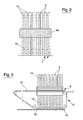
- the overall structure of the press includes the assembly of a plurality of resistant elements 1 arranged facing and aligned consecutively at a predetermined distance from one another, obtained using appropriate spacers.
- the resistant elements 1 and in particular the annular elements or arches 2 are assemblable with an arrangement and a modular organisation by virtue of which the variation in the number of the resistant elements 1 assembled enables proportionally varying the maximum-bearable pressing force.
- the spacing of the annular elements or arches 2 can be realised using spacers 14 located between the facing surfaces of any two consecutive annular elements 2. Such spacers operate only in a perpendicular direction to the annular elements or arches 2 without constituting a constraint to relative displacements in a parallel direction to the elements.
- the pressing action is exerted by the power organ 5 which operates between the facing surfaces 20.
- This organ in the illustrated embodiment, is constituted by a lower body 6 and an upper body 7, between which the objects or the material to be pressed can be inserted, and by a hydraulic actuator which in turn comprises, on a base 8, a chamber 9, into which pressurised fluid is sent.
- the chamber 9 is superiorly sealedly closed by the lower body 6 which functions as a piston.
- the base 8 and the upper body 7 are rested in contact with the facing surfaces 20 present on the resistant elements 1 reciprocally assembled arranged facing and consecutively aligned at a predetermined distance from one another.
- the pressing action is actuated by sending pressurised fluid into the chamber 9 and can be performed on the powder-form material predisposed on the upper branch 11 of a loop-wound conveyor belt 10.
- the upper branch 11 longitudinally crosses the whole press and exhibits a part upstream of the press, where it constitutes the support on which the loads of powder destined to press-forming are prepared, and a downstream part, at which it functions as a conveyor for evacuating the products (slabs).
- the branch 11 is comprised between the lower body 6 and the upper body 7 against which the powder material is compressed and formed during the pressing action.
- the portion of branch 11 involved functions as a lower closure of the die.
- each resistant element 1 is provided with and which are fashioned in a single piece with the corresponding annular element 2.
- the structure of the press of the invention is free of welding and bolting.
- the joining and alignment of the resistant elements 1 are realised using known means which, very schematically, comprise the use of two spacers 40 having an overall parallelepiped shape, which are interposed such as to interact between the ends of the facing surfaces 20, such that between them and the remaining parts of the facing surfaces 20 a compartment is identified, internally of which the whole power organ 5 is housed.
- the interposing of the spacers 40 is actuated such as to realise a predetermined forcing between the ends of the facing surfaces 20 when the press is not under load, such as to guarantee the alignment of the annular elements or arches 2.
- pre-loading wedges 30 can be used, independently and very simply activatable using screw-threaded tie-rods until the predetermined pre-load value is reached.
- the pre-load value is determined such that when the press is functioning the reaction stress to the material pressing, shared among the single resistant elements, totally annuls any forcing of the spacers.
- the pre-loading has a double function: it keeps the machine together and makes the structure absolutely rigid with the machine inactive, and in the first pressing stage, i.e. up to when the overall value of the pressing force exceeds the pre-load value.
- This possibility is particularly important in powder pressing for forming slabs and tiles because it enables adaptation of the pressing action to the variation in the behaviour of the material (prevalently plastic in the initial stage, prevalently elastic in the final stage).
- the particular geometry of the full-thickness cuts 3 present in the annular elements or arches 2 distributes, gradually and quite uniformly, the tensions induced in the material in the zones at greater risk of concentration, thus enabling not only an optimisation of the resistance to fatigue, but also a better exploitation of the material itself (with a further reduction in weight, etc.).
Landscapes
- Engineering & Computer Science (AREA)
- Mechanical Engineering (AREA)
- Manufacturing & Machinery (AREA)
- Chemical & Material Sciences (AREA)
- Ceramic Engineering (AREA)
- Press-Shaping Or Shaping Using Conveyers (AREA)
- Measuring Oxygen Concentration In Cells (AREA)
- Processing Of Stones Or Stones Resemblance Materials (AREA)
- Devices For Post-Treatments, Processing, Supply, Discharge, And Other Processes (AREA)
- Current-Collector Devices For Electrically Propelled Vehicles (AREA)
Priority Applications (1)
| Application Number | Priority Date | Filing Date | Title |
|---|---|---|---|
| PL11776895T PL2632672T3 (pl) | 2010-10-28 | 2011-10-11 | Konstrukcja dla pras, w szczególności do formowania wyrobów ceramicznych |
Applications Claiming Priority (2)
| Application Number | Priority Date | Filing Date | Title |
|---|---|---|---|
| ITMO2010A000301A IT1402937B1 (it) | 2010-10-28 | 2010-10-28 | Struttura per presse in particolare per la formatura di prodotti ceramici. |
| PCT/IB2011/054466 WO2012056347A1 (en) | 2010-10-28 | 2011-10-11 | A structure for presses, in particular for forming ceramic products |
Publications (2)
| Publication Number | Publication Date |
|---|---|
| EP2632672A1 EP2632672A1 (en) | 2013-09-04 |
| EP2632672B1 true EP2632672B1 (en) | 2014-06-25 |
Family
ID=43738176
Family Applications (1)
| Application Number | Title | Priority Date | Filing Date |
|---|---|---|---|
| EP11776895.2A Active EP2632672B1 (en) | 2010-10-28 | 2011-10-11 | A structure for presses, in particular for forming ceramic products |
Country Status (10)
| Country | Link |
|---|---|
| US (1) | US8857327B2 (pl) |
| EP (1) | EP2632672B1 (pl) |
| CN (1) | CN103124621B (pl) |
| BR (1) | BR112013007045B1 (pl) |
| ES (1) | ES2488169T3 (pl) |
| IT (1) | IT1402937B1 (pl) |
| PL (1) | PL2632672T3 (pl) |
| PT (1) | PT2632672E (pl) |
| RU (1) | RU2580864C2 (pl) |
| WO (1) | WO2012056347A1 (pl) |
Families Citing this family (7)
| Publication number | Priority date | Publication date | Assignee | Title |
|---|---|---|---|---|
| CN107073745B (zh) * | 2014-09-19 | 2020-05-08 | 斯蒂-B及T集团股份公司 | 用于大尺寸产品的压制设备 |
| WO2016069573A1 (en) * | 2014-10-27 | 2016-05-06 | Corning Incorporated | Die body apparatus and methods |
| ES2971161T3 (es) * | 2015-03-20 | 2024-06-03 | Siti B & T Group Spa | Grupo de paneles de extremo de una prensa para productos cerámicos y similares |
| CA3051615C (en) * | 2015-05-15 | 2021-06-01 | Usnr/Kockums Cancar Company | Modular press |
| IT201800005716A1 (it) * | 2018-05-25 | 2019-11-25 | Macchina per la formatura di manufatti ceramici | |
| CN108905898B (zh) * | 2018-09-29 | 2024-06-04 | 河南天钻晶体材料有限公司 | 拱形承载铰链梁体、拱形承载铰链梁体总成和六面顶压机 |
| IT202000014728A1 (it) * | 2020-06-19 | 2021-12-19 | Biopsybell S R L | Sacca flessibile per la preparazione di innesti di tessuto adiposo e relativo kit |
Family Cites Families (9)
| Publication number | Priority date | Publication date | Assignee | Title |
|---|---|---|---|---|
| US3064558A (en) * | 1955-03-18 | 1962-11-20 | Asea Ab | Press stand |
| GB1240823A (en) * | 1967-07-26 | 1971-07-28 | Vickers Ltd | Improvements in frames for presses |
| US4155476A (en) * | 1977-12-21 | 1979-05-22 | Autoclave Engineers, Inc. | Hanging reaction frame assembly |
| SU1701530A1 (ru) * | 1989-06-26 | 1991-12-30 | Специализированная Проектно-Конструкторская И Наладочная Организация "Росоргтехстром" | Пресс дл формовани керамических изделий |
| RU2151694C1 (ru) * | 1998-10-19 | 2000-06-27 | ЗАО Воронежское по выпуску тяжелых механических прессов | Способ полусухого формования сырца кирпича на прессе |
| DE19949473C1 (de) * | 1999-10-14 | 2000-10-05 | Joachim Utsch | Hydraulische Tischpresse, insbesondere zum Prägen von Blechschildern |
| ES2176149T3 (es) * | 2000-01-21 | 2002-12-01 | Ronflette Sa | Estructura mejorada para prensa, en particular para moldeo de productos ceramicos. |
| MXPA04003706A (es) * | 2001-11-06 | 2004-07-30 | System Spa | Estructura para prensas, en particular para formar productos ceramicos. |
| ITRE20040151A1 (it) * | 2004-12-10 | 2005-03-10 | Sacmi | Impianto perfezionato per la formatura di lastre o piastrelle ceramiche |
-
2010
- 2010-10-28 IT ITMO2010A000301A patent/IT1402937B1/it active
-
2011
- 2011-10-11 ES ES11776895.2T patent/ES2488169T3/es active Active
- 2011-10-11 WO PCT/IB2011/054466 patent/WO2012056347A1/en not_active Ceased
- 2011-10-11 EP EP11776895.2A patent/EP2632672B1/en active Active
- 2011-10-11 RU RU2013111164/03A patent/RU2580864C2/ru active
- 2011-10-11 PL PL11776895T patent/PL2632672T3/pl unknown
- 2011-10-11 CN CN201180046701.3A patent/CN103124621B/zh active Active
- 2011-10-11 BR BR112013007045A patent/BR112013007045B1/pt active IP Right Grant
- 2011-10-11 PT PT117768952T patent/PT2632672E/pt unknown
- 2011-10-11 US US13/876,704 patent/US8857327B2/en active Active
Also Published As
| Publication number | Publication date |
|---|---|
| WO2012056347A1 (en) | 2012-05-03 |
| BR112013007045B1 (pt) | 2020-01-21 |
| PT2632672E (pt) | 2014-09-08 |
| ITMO20100301A1 (it) | 2012-04-29 |
| PL2632672T3 (pl) | 2014-11-28 |
| US8857327B2 (en) | 2014-10-14 |
| RU2580864C2 (ru) | 2016-04-10 |
| ES2488169T3 (es) | 2014-08-26 |
| RU2013111164A (ru) | 2014-12-10 |
| BR112013007045A2 (pt) | 2016-06-14 |
| US20130206024A1 (en) | 2013-08-15 |
| CN103124621A (zh) | 2013-05-29 |
| IT1402937B1 (it) | 2013-09-27 |
| EP2632672A1 (en) | 2013-09-04 |
| CN103124621B (zh) | 2015-08-19 |
Similar Documents
| Publication | Publication Date | Title |
|---|---|---|
| EP2632672B1 (en) | A structure for presses, in particular for forming ceramic products | |
| EP3009245B1 (en) | Stone cutting device | |
| CN104085128B (zh) | 组合式双向预应力承载机架 | |
| EP1441899B1 (en) | A structure for presses, in particular for forming ceramic products | |
| CN207446998U (zh) | 工件整形装置 | |
| EP1008438B2 (en) | A structure for presses, in particular for forming ceramic products | |
| CN101633194B (zh) | 一种用于生产中纤板和刨花板的双钢带压机 | |
| CN104129094B (zh) | 组合式双x型复合导向系统 | |
| SE516796C2 (sv) | Tryckcellspress och förfarande innefattande förspända och lindade lamellorgan | |
| RU2294811C2 (ru) | Пресс-молот | |
| EP1118456A1 (en) | An improved structure for a press, in particular for moulding ceramic products | |
| SE520583C2 (sv) | Pressanläggning av en tryckcellspress med en tråganordning delbar i en övre och nedre del samt förfarande för anläggningen och användning av anordningen | |
| RU2381085C2 (ru) | Пресс-молот | |
| CN218340984U (zh) | 一种金属制品的压铸模具 | |
| CN213354936U (zh) | 一种平板式铝塑包装机 | |
| EP4622797A1 (en) | Pulp bale press for compressing pulp bales and method of compressing | |
| RU2379149C2 (ru) | Пресс-молот | |
| RU2320445C2 (ru) | Пресс-молот | |
| CN1843752A (zh) | 全自动履带式生物质压块机 | |
| RU92816U1 (ru) | Устройство равноканального углового прессования | |
| EP1327513A3 (en) | Press for moulding products from ceramic materials | |
| UA50929A (uk) | Гідравлічні ножиці |
Legal Events
| Date | Code | Title | Description |
|---|---|---|---|
| PUAI | Public reference made under article 153(3) epc to a published international application that has entered the european phase |
Free format text: ORIGINAL CODE: 0009012 |
|
| 17P | Request for examination filed |
Effective date: 20130321 |
|
| AK | Designated contracting states |
Kind code of ref document: A1 Designated state(s): AL AT BE BG CH CY CZ DE DK EE ES FI FR GB GR HR HU IE IS IT LI LT LU LV MC MK MT NL NO PL PT RO RS SE SI SK SM TR |
|
| DAX | Request for extension of the european patent (deleted) | ||
| RIC1 | Information provided on ipc code assigned before grant |
Ipc: B28B 3/02 20060101AFI20140204BHEP Ipc: B30B 15/04 20060101ALI20140204BHEP Ipc: B30B 5/04 20060101ALI20140204BHEP |
|
| GRAP | Despatch of communication of intention to grant a patent |
Free format text: ORIGINAL CODE: EPIDOSNIGR1 |
|
| INTG | Intention to grant announced |
Effective date: 20140320 |
|
| GRAS | Grant fee paid |
Free format text: ORIGINAL CODE: EPIDOSNIGR3 |
|
| GRAA | (expected) grant |
Free format text: ORIGINAL CODE: 0009210 |
|
| AK | Designated contracting states |
Kind code of ref document: B1 Designated state(s): AL AT BE BG CH CY CZ DE DK EE ES FI FR GB GR HR HU IE IS IT LI LT LU LV MC MK MT NL NO PL PT RO RS SE SI SK SM TR |
|
| REG | Reference to a national code |
Ref country code: GB Ref legal event code: FG4D |
|
| REG | Reference to a national code |
Ref country code: CH Ref legal event code: EP |
|
| REG | Reference to a national code |
Ref country code: AT Ref legal event code: REF Ref document number: 674340 Country of ref document: AT Kind code of ref document: T Effective date: 20140715 |
|
| REG | Reference to a national code |
Ref country code: IE Ref legal event code: FG4D |
|
| REG | Reference to a national code |
Ref country code: DE Ref legal event code: R096 Ref document number: 602011008022 Country of ref document: DE Effective date: 20140814 |
|
| REG | Reference to a national code |
Ref country code: ES Ref legal event code: FG2A Ref document number: 2488169 Country of ref document: ES Kind code of ref document: T3 Effective date: 20140826 |
|
| REG | Reference to a national code |
Ref country code: PT Ref legal event code: SC4A Free format text: AVAILABILITY OF NATIONAL TRANSLATION Effective date: 20140827 |
|
| REG | Reference to a national code |
Ref country code: NL Ref legal event code: T3 |
|
| PG25 | Lapsed in a contracting state [announced via postgrant information from national office to epo] |
Ref country code: NO Free format text: LAPSE BECAUSE OF FAILURE TO SUBMIT A TRANSLATION OF THE DESCRIPTION OR TO PAY THE FEE WITHIN THE PRESCRIBED TIME-LIMIT Effective date: 20140925 Ref country code: CY Free format text: LAPSE BECAUSE OF FAILURE TO SUBMIT A TRANSLATION OF THE DESCRIPTION OR TO PAY THE FEE WITHIN THE PRESCRIBED TIME-LIMIT Effective date: 20140625 Ref country code: FI Free format text: LAPSE BECAUSE OF FAILURE TO SUBMIT A TRANSLATION OF THE DESCRIPTION OR TO PAY THE FEE WITHIN THE PRESCRIBED TIME-LIMIT Effective date: 20140625 Ref country code: LT Free format text: LAPSE BECAUSE OF FAILURE TO SUBMIT A TRANSLATION OF THE DESCRIPTION OR TO PAY THE FEE WITHIN THE PRESCRIBED TIME-LIMIT Effective date: 20140625 Ref country code: GR Free format text: LAPSE BECAUSE OF FAILURE TO SUBMIT A TRANSLATION OF THE DESCRIPTION OR TO PAY THE FEE WITHIN THE PRESCRIBED TIME-LIMIT Effective date: 20140926 |
|
| REG | Reference to a national code |
Ref country code: AT Ref legal event code: MK05 Ref document number: 674340 Country of ref document: AT Kind code of ref document: T Effective date: 20140625 |
|
| REG | Reference to a national code |
Ref country code: LT Ref legal event code: MG4D |
|
| PG25 | Lapsed in a contracting state [announced via postgrant information from national office to epo] |
Ref country code: LV Free format text: LAPSE BECAUSE OF FAILURE TO SUBMIT A TRANSLATION OF THE DESCRIPTION OR TO PAY THE FEE WITHIN THE PRESCRIBED TIME-LIMIT Effective date: 20140625 Ref country code: RS Free format text: LAPSE BECAUSE OF FAILURE TO SUBMIT A TRANSLATION OF THE DESCRIPTION OR TO PAY THE FEE WITHIN THE PRESCRIBED TIME-LIMIT Effective date: 20140625 Ref country code: HR Free format text: LAPSE BECAUSE OF FAILURE TO SUBMIT A TRANSLATION OF THE DESCRIPTION OR TO PAY THE FEE WITHIN THE PRESCRIBED TIME-LIMIT Effective date: 20140625 Ref country code: SE Free format text: LAPSE BECAUSE OF FAILURE TO SUBMIT A TRANSLATION OF THE DESCRIPTION OR TO PAY THE FEE WITHIN THE PRESCRIBED TIME-LIMIT Effective date: 20140625 |
|
| REG | Reference to a national code |
Ref country code: PL Ref legal event code: T3 |
|
| PG25 | Lapsed in a contracting state [announced via postgrant information from national office to epo] |
Ref country code: SK Free format text: LAPSE BECAUSE OF FAILURE TO SUBMIT A TRANSLATION OF THE DESCRIPTION OR TO PAY THE FEE WITHIN THE PRESCRIBED TIME-LIMIT Effective date: 20140625 Ref country code: EE Free format text: LAPSE BECAUSE OF FAILURE TO SUBMIT A TRANSLATION OF THE DESCRIPTION OR TO PAY THE FEE WITHIN THE PRESCRIBED TIME-LIMIT Effective date: 20140625 Ref country code: CZ Free format text: LAPSE BECAUSE OF FAILURE TO SUBMIT A TRANSLATION OF THE DESCRIPTION OR TO PAY THE FEE WITHIN THE PRESCRIBED TIME-LIMIT Effective date: 20140625 Ref country code: RO Free format text: LAPSE BECAUSE OF FAILURE TO SUBMIT A TRANSLATION OF THE DESCRIPTION OR TO PAY THE FEE WITHIN THE PRESCRIBED TIME-LIMIT Effective date: 20140625 |
|
| PG25 | Lapsed in a contracting state [announced via postgrant information from national office to epo] |
Ref country code: AT Free format text: LAPSE BECAUSE OF FAILURE TO SUBMIT A TRANSLATION OF THE DESCRIPTION OR TO PAY THE FEE WITHIN THE PRESCRIBED TIME-LIMIT Effective date: 20140625 Ref country code: IS Free format text: LAPSE BECAUSE OF FAILURE TO SUBMIT A TRANSLATION OF THE DESCRIPTION OR TO PAY THE FEE WITHIN THE PRESCRIBED TIME-LIMIT Effective date: 20141025 |
|
| REG | Reference to a national code |
Ref country code: DE Ref legal event code: R097 Ref document number: 602011008022 Country of ref document: DE |
|
| PG25 | Lapsed in a contracting state [announced via postgrant information from national office to epo] |
Ref country code: DK Free format text: LAPSE BECAUSE OF FAILURE TO SUBMIT A TRANSLATION OF THE DESCRIPTION OR TO PAY THE FEE WITHIN THE PRESCRIBED TIME-LIMIT Effective date: 20140625 |
|
| PLBE | No opposition filed within time limit |
Free format text: ORIGINAL CODE: 0009261 |
|
| STAA | Information on the status of an ep patent application or granted ep patent |
Free format text: STATUS: NO OPPOSITION FILED WITHIN TIME LIMIT |
|
| PG25 | Lapsed in a contracting state [announced via postgrant information from national office to epo] |
Ref country code: LU Free format text: LAPSE BECAUSE OF FAILURE TO SUBMIT A TRANSLATION OF THE DESCRIPTION OR TO PAY THE FEE WITHIN THE PRESCRIBED TIME-LIMIT Effective date: 20141011 Ref country code: MC Free format text: LAPSE BECAUSE OF FAILURE TO SUBMIT A TRANSLATION OF THE DESCRIPTION OR TO PAY THE FEE WITHIN THE PRESCRIBED TIME-LIMIT Effective date: 20140625 |
|
| REG | Reference to a national code |
Ref country code: CH Ref legal event code: PL |
|
| 26N | No opposition filed |
Effective date: 20150326 |
|
| REG | Reference to a national code |
Ref country code: IE Ref legal event code: MM4A |
|
| PG25 | Lapsed in a contracting state [announced via postgrant information from national office to epo] |
Ref country code: CH Free format text: LAPSE BECAUSE OF NON-PAYMENT OF DUE FEES Effective date: 20141031 Ref country code: LI Free format text: LAPSE BECAUSE OF NON-PAYMENT OF DUE FEES Effective date: 20141031 |
|
| REG | Reference to a national code |
Ref country code: FR Ref legal event code: ST Effective date: 20150630 |
|
| PG25 | Lapsed in a contracting state [announced via postgrant information from national office to epo] |
Ref country code: FR Free format text: LAPSE BECAUSE OF NON-PAYMENT OF DUE FEES Effective date: 20141031 |
|
| PG25 | Lapsed in a contracting state [announced via postgrant information from national office to epo] |
Ref country code: IE Free format text: LAPSE BECAUSE OF NON-PAYMENT OF DUE FEES Effective date: 20141011 |
|
| PG25 | Lapsed in a contracting state [announced via postgrant information from national office to epo] |
Ref country code: SI Free format text: LAPSE BECAUSE OF FAILURE TO SUBMIT A TRANSLATION OF THE DESCRIPTION OR TO PAY THE FEE WITHIN THE PRESCRIBED TIME-LIMIT Effective date: 20140625 |
|
| PG25 | Lapsed in a contracting state [announced via postgrant information from national office to epo] |
Ref country code: SM Free format text: LAPSE BECAUSE OF FAILURE TO SUBMIT A TRANSLATION OF THE DESCRIPTION OR TO PAY THE FEE WITHIN THE PRESCRIBED TIME-LIMIT Effective date: 20140625 |
|
| GBPC | Gb: european patent ceased through non-payment of renewal fee |
Effective date: 20151011 |
|
| PG25 | Lapsed in a contracting state [announced via postgrant information from national office to epo] |
Ref country code: BG Free format text: LAPSE BECAUSE OF FAILURE TO SUBMIT A TRANSLATION OF THE DESCRIPTION OR TO PAY THE FEE WITHIN THE PRESCRIBED TIME-LIMIT Effective date: 20140625 |
|
| PG25 | Lapsed in a contracting state [announced via postgrant information from national office to epo] |
Ref country code: MT Free format text: LAPSE BECAUSE OF FAILURE TO SUBMIT A TRANSLATION OF THE DESCRIPTION OR TO PAY THE FEE WITHIN THE PRESCRIBED TIME-LIMIT Effective date: 20140625 Ref country code: GB Free format text: LAPSE BECAUSE OF NON-PAYMENT OF DUE FEES Effective date: 20151011 Ref country code: HU Free format text: LAPSE BECAUSE OF FAILURE TO SUBMIT A TRANSLATION OF THE DESCRIPTION OR TO PAY THE FEE WITHIN THE PRESCRIBED TIME-LIMIT; INVALID AB INITIO Effective date: 20111011 Ref country code: BE Free format text: LAPSE BECAUSE OF FAILURE TO SUBMIT A TRANSLATION OF THE DESCRIPTION OR TO PAY THE FEE WITHIN THE PRESCRIBED TIME-LIMIT Effective date: 20140625 |
|
| PG25 | Lapsed in a contracting state [announced via postgrant information from national office to epo] |
Ref country code: MK Free format text: LAPSE BECAUSE OF FAILURE TO SUBMIT A TRANSLATION OF THE DESCRIPTION OR TO PAY THE FEE WITHIN THE PRESCRIBED TIME-LIMIT Effective date: 20140625 |
|
| PG25 | Lapsed in a contracting state [announced via postgrant information from national office to epo] |
Ref country code: AL Free format text: LAPSE BECAUSE OF FAILURE TO SUBMIT A TRANSLATION OF THE DESCRIPTION OR TO PAY THE FEE WITHIN THE PRESCRIBED TIME-LIMIT Effective date: 20140625 |
|
| REG | Reference to a national code |
Ref country code: NL Ref legal event code: PD Owner name: SYSTEM CERAMICS S.P.A.; IT Free format text: DETAILS ASSIGNMENT: CHANGE OF OWNER(S), ASSIGNMENT; FORMER OWNER NAME: SYSTEM S.P.A. Effective date: 20191210 |
|
| REG | Reference to a national code |
Ref country code: ES Ref legal event code: PC2A Owner name: SYSTEM CERAMICS S.P.A. Effective date: 20200124 |
|
| REG | Reference to a national code |
Ref country code: DE Ref legal event code: R082 Ref document number: 602011008022 Country of ref document: DE Representative=s name: WITTE, WELLER & PARTNER PATENTANWAELTE MBB, DE Ref country code: DE Ref legal event code: R081 Ref document number: 602011008022 Country of ref document: DE Owner name: SYSTEM CERAMICS S.P.A., FIORANO MODENESE, IT Free format text: FORMER OWNER: SYSTEM S.P.A., FIORANO MODENESE, MODENA, IT |
|
| P01 | Opt-out of the competence of the unified patent court (upc) registered |
Effective date: 20230525 |
|
| PGFP | Annual fee paid to national office [announced via postgrant information from national office to epo] |
Ref country code: PT Payment date: 20250923 Year of fee payment: 15 |
|
| PGFP | Annual fee paid to national office [announced via postgrant information from national office to epo] |
Ref country code: PL Payment date: 20250918 Year of fee payment: 15 Ref country code: TR Payment date: 20250925 Year of fee payment: 15 |
|
| PGFP | Annual fee paid to national office [announced via postgrant information from national office to epo] |
Ref country code: NL Payment date: 20251026 Year of fee payment: 15 |
|
| PGFP | Annual fee paid to national office [announced via postgrant information from national office to epo] |
Ref country code: DE Payment date: 20251029 Year of fee payment: 15 |
|
| PGFP | Annual fee paid to national office [announced via postgrant information from national office to epo] |
Ref country code: IT Payment date: 20251021 Year of fee payment: 15 |
|
| PGFP | Annual fee paid to national office [announced via postgrant information from national office to epo] |
Ref country code: ES Payment date: 20251103 Year of fee payment: 15 |