EP2631968A2 - Elektrisches element mit einer neuen struktur für verbesserte sicherheit - Google Patents
Elektrisches element mit einer neuen struktur für verbesserte sicherheit Download PDFInfo
- Publication number
- EP2631968A2 EP2631968A2 EP11834589.1A EP11834589A EP2631968A2 EP 2631968 A2 EP2631968 A2 EP 2631968A2 EP 11834589 A EP11834589 A EP 11834589A EP 2631968 A2 EP2631968 A2 EP 2631968A2
- Authority
- EP
- European Patent Office
- Prior art keywords
- battery
- conductive member
- external short
- short induction
- induction kit
- Prior art date
- Legal status (The legal status is an assumption and is not a legal conclusion. Google has not performed a legal analysis and makes no representation as to the accuracy of the status listed.)
- Granted
Links
Images



Classifications
-
- H—ELECTRICITY
- H01—ELECTRIC ELEMENTS
- H01M—PROCESSES OR MEANS, e.g. BATTERIES, FOR THE DIRECT CONVERSION OF CHEMICAL ENERGY INTO ELECTRICAL ENERGY
- H01M50/00—Constructional details or processes of manufacture of the non-active parts of electrochemical cells other than fuel cells, e.g. hybrid cells
- H01M50/50—Current conducting connections for cells or batteries
- H01M50/572—Means for preventing undesired use or discharge
-
- H—ELECTRICITY
- H01—ELECTRIC ELEMENTS
- H01M—PROCESSES OR MEANS, e.g. BATTERIES, FOR THE DIRECT CONVERSION OF CHEMICAL ENERGY INTO ELECTRICAL ENERGY
- H01M10/00—Secondary cells; Manufacture thereof
- H01M10/02—Details
-
- H—ELECTRICITY
- H01—ELECTRIC ELEMENTS
- H01M—PROCESSES OR MEANS, e.g. BATTERIES, FOR THE DIRECT CONVERSION OF CHEMICAL ENERGY INTO ELECTRICAL ENERGY
- H01M10/00—Secondary cells; Manufacture thereof
- H01M10/05—Accumulators with non-aqueous electrolyte
- H01M10/052—Li-accumulators
-
- H—ELECTRICITY
- H01—ELECTRIC ELEMENTS
- H01M—PROCESSES OR MEANS, e.g. BATTERIES, FOR THE DIRECT CONVERSION OF CHEMICAL ENERGY INTO ELECTRICAL ENERGY
- H01M10/00—Secondary cells; Manufacture thereof
- H01M10/42—Methods or arrangements for servicing or maintenance of secondary cells or secondary half-cells
-
- H—ELECTRICITY
- H01—ELECTRIC ELEMENTS
- H01M—PROCESSES OR MEANS, e.g. BATTERIES, FOR THE DIRECT CONVERSION OF CHEMICAL ENERGY INTO ELECTRICAL ENERGY
- H01M50/00—Constructional details or processes of manufacture of the non-active parts of electrochemical cells other than fuel cells, e.g. hybrid cells
- H01M50/50—Current conducting connections for cells or batteries
- H01M50/531—Electrode connections inside a battery casing
-
- H—ELECTRICITY
- H01—ELECTRIC ELEMENTS
- H01M—PROCESSES OR MEANS, e.g. BATTERIES, FOR THE DIRECT CONVERSION OF CHEMICAL ENERGY INTO ELECTRICAL ENERGY
- H01M50/00—Constructional details or processes of manufacture of the non-active parts of electrochemical cells other than fuel cells, e.g. hybrid cells
- H01M50/50—Current conducting connections for cells or batteries
- H01M50/572—Means for preventing undesired use or discharge
- H01M50/574—Devices or arrangements for the interruption of current
-
- H—ELECTRICITY
- H01—ELECTRIC ELEMENTS
- H01M—PROCESSES OR MEANS, e.g. BATTERIES, FOR THE DIRECT CONVERSION OF CHEMICAL ENERGY INTO ELECTRICAL ENERGY
- H01M2200/00—Safety devices for primary or secondary batteries
-
- Y—GENERAL TAGGING OF NEW TECHNOLOGICAL DEVELOPMENTS; GENERAL TAGGING OF CROSS-SECTIONAL TECHNOLOGIES SPANNING OVER SEVERAL SECTIONS OF THE IPC; TECHNICAL SUBJECTS COVERED BY FORMER USPC CROSS-REFERENCE ART COLLECTIONS [XRACs] AND DIGESTS
- Y02—TECHNOLOGIES OR APPLICATIONS FOR MITIGATION OR ADAPTATION AGAINST CLIMATE CHANGE
- Y02E—REDUCTION OF GREENHOUSE GAS [GHG] EMISSIONS, RELATED TO ENERGY GENERATION, TRANSMISSION OR DISTRIBUTION
- Y02E60/00—Enabling technologies; Technologies with a potential or indirect contribution to GHG emissions mitigation
- Y02E60/10—Energy storage using batteries
Definitions
- the present invention disclosed herein relates to a novel structural electric device having improved safety, and more particularly, to a novel structural electric device devised to resolve several issues regarding heat generation, ignition, and explosion, which may be caused by a sharp needle-shaped object penetrating an electric device.
- a secondary battery is classified into a cylindrical type, a polygonal type, and a pouch type according to packaging types and manufacturing methods and has been developed and manufactured until now.
- Measures to deal with an issue of a sharp needle-shaped object penetrating into a secondary battery or an issue occurring during a test for a needle-shaped penetration in a secondary battery may vary according to packaging types and manufacturing methods. However, most of the measures may not provide reliable solutions. This is because there is no sure solution to basically resolve a short phenomenon between electrodes that constitute a battery.
- the explosion cause may be inferred as follows.
- a penetrating material has high electrical conductivity, it causes a short between positive and negative electrodes in a secondary battery. Also, due to this, current flows internally. As a result, a deterioration phenomenon of the secondary battery occurs easily and furthermore an ignition or explosion phenomenon occurs also.
- the present invention provides an electric device basically improving the stability thereof further more when there is a penetration issue of the electric device caused by a sharp needle-shaped object.
- the present invention also provides an external short induction kit for inducing an external short of an electric device. Accordingly, when a sharp needle-shaped object penetrates the electric device, the external short induction kit receives an attack from the sharp needle-shaped object first to protect the electric device.
- the external short kit induces a compulsory external short to lower the voltage and energy of the electric device, even when a needle-shaped object enters into the electric device, an amount of internally-flowing current is limited. Thus, an issue regarding explosion of the electric device due to a needle-shaped penetration in the electricity device may be basically resolved.
- Embodiments of the present invention provide external short induction kits of an electric device include: at least two conductive members; at least two connectors having one side connected to the conductive member and the other side connected to an electrode of the electric device or a connection part, the connection part being an electrical pathway between electrodes of the electric device; and an insulation layer interposed between the at least two conductive members.
- the electric device may be one of a secondary battery, a battery module including a plurality of unit batteries, and a battery pack including the plurality of battery modules but is not limited thereto.
- secondary batteries in which a unit battery including a positive electrode, a negative electrode, and a separation layer is connected to at least one external short induction kit are provided.
- the external short induction kit may include: a first conductive member; a first connector connecting the first conductive member and a positive electrode of the unit battery; a second conductive member; a second connector connecting the second conductive member and a negative electrode of the unit battery; and an insulation layer interposed between the first conductive member and the second conductive member.
- the external short induction kit may further include an exterior finishing material.
- each of the first conductive member and the second conductive member may be formed of at least one selected from the group consisting of Cu, Al, Pt, Au, Pd, Ir, Ag, Ru, Ni, STS, Mo, V, Zn, Co, Ca, Li, Sn, Cd, Os, Rh, Cr, Ti, W, Fe, and alloys thereof but is not limited thereto.
- each of the first connector and the second connector may be formed of at least one selected from the group consisting of Cu, Al, Pt, Au, Pd, Ir, Ag, Ru, Ni, STS, Mo, V, Zn, Co, Ca, Li, Sn, Cd, Os, Rh, Cr, Ti, W, Fe, and alloys thereof but is not limited thereto
- the insulation layer may include one of an air layer, a material layer having insulation property; and a multi layer including a material layer having insulation property and an air layer, but is not limited thereto.
- the air layer may be a layer between the conductive members prepared when grooves spaced from each other are formed in the inner side of an exterior finishing material of the external short induction kit and conductive members are inserted into and fixed at the grooves, but is not limited thereto.
- a material having insulation property used for the material layer and the multi layer is may be least one selected from the group consisting of polypropylene, polyethylene, polyethyleneterephthalate (PET), polyethylene-2,6-naphthalene dicarboxylate (PEN), and polycarbonate resin, but is not limited thereto.
- the external short induction kit may be disposed above the broadest surface among external surfaces of an exterior finishing material of the unit battery, but is not limited thereto.
- the secondary batteries may further include an insulation part between the external short induction kit and the exterior finishing material of the unit battery.
- the insulation part may be formed of at least one selected from the group consisting of polypropylene, polyethylene, polyethyleneterephthalate (PET), polyethylene-2,6-naphthalene dicarboxylate (PEN), and polycarbonate resin, but is not limited thereto.
- battery modules in which electrodes of a plurality of unit batteries or connection parts connecting the plurality of unit batteries in series or parallel are connected to at least one external short induction kit for battery module.
- the external short induction kit for battery module includes: a first conductive member; a first connector connecting the first conductive member and a positive electrode of one of the plurality of unit batteries; a second conductive member; a second connector connecting the second conductive member and a negative electrode of one of the plurality of unit batteries; a third conductive member; a third conductor connecting the third conductive member and connection parts connecting the plurality of unit batteries in series or parallel; and an insulation layer interposed between the conductive members.
- the numbers of the third conductive members and the third connectors may be identical to that of the connection parts connecting the plurality of unit batteries in series or parallel, but is not limited thereto.
- the external short induction kit for battery module may be disposed on an external surface of an exterior finishing material of the battery module, but is not limited thereto.
- battery packs include the battery module.
- the battery pack may be used as power for at least one of power tools, Electric Vehicles (EVs), Hybrid Electric Vehicles (HEVs), Plug-in Hybrid Electric Vehicles (PHEVs), E-bikes, E-scooters; electric golf carts, electric trucks, and electric commercial vehicles, but is not limited thereto.
- EVs Electric Vehicles
- HEVs Hybrid Electric Vehicles
- PHEVs Plug-in Hybrid Electric Vehicles
- E-bikes E-scooters
- electric golf carts electric trucks, and electric commercial vehicles, but is not limited thereto.
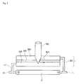
- FIG. 1 is a schematic view when a unit battery is connected to one external short induction kit according to an embodiment of the present invention
- FIG. 2 is a schematic view when a needle-shaped object penetrates one external short induction kit connected to a unit battery according to an embodiment of the present invention
- FIG. 3 is a schematic view when a needle-shaped object penetrates one external short induction kit connected to a unit battery and the unit battery according to an embodiment of the present invention
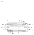
- FIG. 4 is a schematic view when a unit battery is connected to two external short induction kits according to another embodiment of the present invention.
- FIG. 5 is a schematic view of a battery module according to an embodiment of the present invention.
- the present invention provides an external short induction kit of an electric device to resolve the ignition and furthermore the explosion of the electric device, which may be caused by a needle-shaped object penetrating the electric device.
- the external short induction kit of the electric device according to the present invention includes at least two conductive members, at least two connectors, and an insulation layer.
- the at least two conductive members cause a short after being penetrated by a needle-shaped object and are electrically connected to electrodes of the electric device.
- the at least two connectors serve to electrically connect the at least two conductive members and the electric device.
- one end of the connector is connected to the conductive member and the other one is connected to the electrode of the electric device or a connection part (i.e., an electrical pathway between electrodes of the electric device).
- the insulation layer is interposed between the at least two conductive members and serves to prevent a short in the at least two conductive member when the electric device operates normally.
- a short occurs between the at least two conductive members.
- a current path is formed in the at least two conductive member and the needle-shaped object. Due to the current in the current path, the voltage and energy of the electric device are lowered primarily, thereby allowing the electric device to reach a stable state.
- Nonrestrictive examples of the electric device may include a secondary cell, a battery module having a plurality of unit batteries, and a battery pack having a plurality of battery modules.
- the external short induction kit may be applied to one of the above listed electric devices according to only an embodiment but is not limited thereto. Additionally, the drawings are illustrated according to only an embodiment and thus the spirit of the present invention is not limited to the components in the drawings.
- the secondary battery may include a unit battery having at least one positive electrode, negative electrode, and separation layer and at least one external short induction kit, which are connected to each other.
- the external short induction kit may include a first conductive member; a first connector connecting the first conductive member and the positive electrode of the unit battery; a second conductive member; a second connector connecting the second conductive member and the negative electrode of the unit battery; and an insulation layer interposed between the first conductive member and the second conductive member.
- the external short induction kit may adjust the numbers of the first conductive members and the second conductive members according to the number of electrodes that the unit battery includes and the forms of the unit battery and, of course, may adjust the numbers of the first and second conductors and the insulation layers according to the numbers of the first and second conductive members.
- the numbers of the first conductive members and the first conductors included may be identical to that of the positive electrodes in the unit battery.
- the numbers of the second conductive members and the second connectors included may be identical to that of the negative electrodes in the unit battery.
- the numbers of the first and second conductive members included are greater than that of the electrodes in the unit battery, the volume of the secondary battery is increased, so that the capacity per volume of the secondary battery is decreased.
- the numbers of the first and second conductive members included are less than that of the electrodes in the unit battery, an internal short may occur between the electrodes in the unit battery, which are not connected to the external short induction kit. Therefore, it becomes difficult to sufficiently secure the stability of the secondary battery.
- the external short induction kit may be packaged with exterior finishing materials to protect the first and second conductive members but is not limited thereto.
- first and second conductive members may be used for the first and second conductive members without specific restrictions. More preferably, metals and nonmetals having high electrical conductivity, less thermal deformation, and strong oxidation resistance may be used for the first and second conductive members.
- the first conductive member connected to the positive electrode may not be necessarily identical to the second conductive member connected to the negative electrode. That is, the first and second conductive members may be formed of respectively different materials.
- the first conductive member and the second conductive member may be formed of at least one selected from the group consisting of Cu, Al, Pt, Au, Pd, Ir, Ag, Ru, Ni, STS, Mo, V, Zn, Co, Ca, Li, Sn, Cd, Os, Rh, Cr, Ti, W, Fe, and alloys thereof, but are not limited thereto.
- the thicknesses or sizes of the first and second conductive members are not significantly limited, since the thicknesses or sizes are a factor to induce a first short through a needle-shaped penetration in the secondary battery, their thicknesses may be properly manufactured identical or similar to that of the collector of the unit battery and their sizes may be property manufactured identical or similar to that of the unit battery, in order to protect the unit battery.
- first and second connectors have excellent electrical conductivity like the conductive members, they are not specifically limited but, more preferably, they may be formed of metals and nonmetals having high electrical conductivity, less thermal deformation, and strong oxidation resistance.
- the first connector connected to the positive electrode may not be identical to the second connector connected to the negative electrode. That is, the first connector and the second conductor may be formed of respectively different materials.
- the first connector and the second connector may be formed of the same materials as the conductive members but are not limited thereto.
- the insulation layer interposed between the first and second conductive members may be diversely configured to prevent the flow of electricity between the first conductive members 100 and second conductive members 200 when the secondary battery operates normally.
- the insulation layer may be one of an air layer, a material layer having insulation property, and a mufti layer including a material layer having insulation property and an air layer, but is not limited thereto.
- the air layer means air between the first and second conductive members when they are spaced a predetermined distance from each other to prevent the flow of electricity.
- the air layer may be realized through various methods. As one example, after grooves are formed being spaced from each other in the inner side of the exterior finishing material in the external short induction kit, a conductive member is inserted into and fixed at the grooves, in order to form an air layer between the conductive members.
- the material layer having insulation property and the multi layer including a material layer having insulation property and an air layer, prevent the flow of electricity between the first and second conductive members by inserting a material having insulation property therebetween.
- the material layer having insulation property is manufactured with the same area as each of the first conductive member and the second conductive member, and then is interposed therebetween.
- the material layer having insulation property is manufactured with a smaller area than each of the first conductive member and the second conductive member, so that the material layer and air layer having insulation property co-exist.
- the material layer having insulation property may serve as a spacer between the first conductive member and the second conductive member spaced a predetermined distance from each other, in order to prevent the flow of electricity.
- the material used for the material layer and the multi layer may be used without any restriction.
- the material may include at least one selected from the group consisting of polypropylene, polyethylene, polyethyleneterephthalate (PET), polyethylene-2,6-naphthalene dicarboxylate (PEN), and polycarbonate resin, but are not limited thereto.
- shrinking polyethyleneterephthalate (PET) or polyethylene-2,6-naphthalene dicarboxylate (PEN) may be used.
- the position of the external short induction kit may be disposed anywhere on the surface of the unit battery in the secondary battery. However, in order to protect the unit battery most efficiently, the external short induction kit may be disposed on an external broad surface of the exterior finishing material of the unit battery.
- the external short induction kits having different sizes may be deposed on the external six sides of the unit battery, respectively.
- FIG. 1 illustrates a unit battery 2 to which one external short induction kit 1 is connected according to an embodiment of the present invention. Additionally, FIG. 1 illustrates a view when the external short induction kit 1 is disposed above the broad surface of the unit battery 2 to protect it from a needle-shaped object 500 of FIG. 2 .
- an insulation part (not shown) may be additionally disposed between the external short induction kit 1 and the unit battery 2.
- the insulation part may be required to prevent a short between a first conductive member 100 of the external short induction kit 1 and the unit battery 2 and may be included if necessary.
- a material of the insulation part may have the same material having insulation property as the above-mentioned insulation layer but is not limited thereto.
- FIG. 2 illustrates a view when only the external short induction kit 1 in a secondary battery of FIG. 1 is penetrated by the conductive needle-shaped object 500.
- FIG. 3 illustrates a view when both the external short induction kit 1 and the unit battery 2 in the secondary battery of FIG. 1 are penetrated by the conductive needle-shaped object 500.
- the first conductive members 100 and second conductive members 200 may contact each other electrically. As a result, a short occurs between the first conductive members 100 and second conductive members 200.
- a current path 600 is formed in the first conductive member 100, the second conductive member 200, and the needle-shaped object 500. Due to the current in the current path 600, the voltage and energy of the unit battery 2 are lowered first to allow the secondary battery 3 to reach a stable state.
- the unit battery 2 becomes in a stabilized state after the short occurs, thereby preventing the ignition and further more explosion of the secondary battery 3.
- FIG. 4 illustrates a unit battery 2 to which two external short induction kits 1 are connected according to an embodiment of the present invention. Additionally, FIG. 4 illustrates a view when the external short induction kits 1 are disposed above and below the two broad surfaces of the unit battery 2 to protect it from the needle-shaped object 500 of FIG. 2 or 3 .
- FIGS. 1 to 4 The structures in which the external short induction kit 1 of the present invention is connected to the unit battery 2 are described through FIGS. 1 to 4 .
- the external short induction kit 1 may be connected to the unit battery 2 through various structures besides those of FIGS. 1 to 4 .
- the present invention provides a electrodes in a plurality of unit batteries or connection part connecting the plurality of unit batteries in series or parallel and a battery module to which at least one external short induction kit for battery module is connected.
- the external short induction kit for battery module includes a first conductive member; a first connector connecting the first conductive member and a positive electrode of one in the plurality of unit batteries; a second conductive member; a second connector connecting the second conductive member and a negative electrode of one in the plurality of unit batteries; a third conductive member; a third connector connecting the third conductive member and connection parts connecting the plurality of unit batteries in series or parallel; and an insulation layer interposed between the conductive members.
- the conductive members included in the external short induction kit for battery module may be adjusted according to the purpose and capacity of the battery module. More preferably, the fact that all connectors, which connect the electrodes of unit batteries at both ends among a plurality of unit batteries in the battery module and unit batteries aside from those at the both ends among the plurality of unit batteries, are connected to the conductive members matches the purpose of the present invention, which improves the stability of an electric device by using an external short induction kit.
- the numbers of the third conductive members and the third connectors connected to the connection parts connecting the plurality of unit batteries in series or parallel may be identical to that of the connection parts.
- the external short induction kit for battery module may be placed at any position on the surface of the battery module including the plurality of unit batteries. More preferably, the external short induction kit for battery module may be placed at an external broad surface of the battery module in order to protect the battery module most effectively.
- FIG. 5 illustrates a view when electrodes (i.e., positive terminals 10 and negative terminals 11) in a plurality of unit batteries or connection parts 16 are connected to an external short induction kit for battery module.
- electrodes i.e., positive terminals 10 and negative terminals 11
- a unit battery at the outermost among a plurality of unit batteries 2 may be connected to the first conductive member 100 at the outermost opposite to the position of the unit battery in the external short induction kit for battery module.
- a unit battery at the next outermost is connected to a third conductive member 300 at the next outermost opposite to the unit battery in the external short induction kit for battery module.
- the electrodes (i.e., the positive leads 10 and the negative leads 11) in the plurality of unit batteries or the connection parts 16 are sequentially connected to the conductive members 100, 200, and 300 in a structural aspect.
- the structure of the battery module according to an embodiment of the present invention is not limited thereto.
- first and second connectors are connected to the positive leads 10 and the negative leads 11 of the unit battery, respectively, as shown in FIG. 5 , they may be connected to a bus bar 17 connected to the electrode leads and also this corresponds to the present invention. That is, the first and second connectors may be connected to any positions of the unit battery where electricity flows.
- the present invention may provide a battery pack including the battery module.
- the battery pack may be used as power for medium-large sized devices such as power tools, Electric Vehicles (EVs), Hybrid Electric Vehicles (HEVs), Plug-in Hybrid Electric Vehicles (PHEVs), E-bikes, E-scooters; electric golf carts, electric trucks, and electric commercial vehicles, but is not limited thereto.
- EVs Electric Vehicles
- HEVs Hybrid Electric Vehicles
- PHEVs Plug-in Hybrid Electric Vehicles
- E-bikes E-scooters
- electric golf carts electric trucks, and electric commercial vehicles, but is not limited thereto.
- Example unit battery to which external short induction kit is connected
- an aluminum thin layer as a first conductive member, PET as an insulation layer, a copper thin layer as a second conductive member are stacked and a temperature of about 80 °C and a pressure of 100,000 N/m 2 are applied on the stacked layers to complete a first conductive member/insulation layer/second conductive member assembly.
- the first conductive member/insulation layer/second conductive member assembly is connected to a unit battery including a positive electrode, a negative electrode, and a separation layer through a first connector and a second connector, thereby manufacturing the secondary battery according to the present invention.
- Comparative example 1 typical unit battery
- a unit battery not connected to an external short induction kit is used.
- the middle of the unit battery connected to the external short induction kit according to the example 1 was penetrated by a nail having a diameter of about 2.5 mm at about 5m/min speed.
- the external short induction kit was completely penetrated and the unit battery was partially penetrated.
- the external short induction kit become short first to lower the voltage and energy of the unit battery, even when the unit battery was partially penetrated by the nail having a diameter of about 2.5 mm, it was observed that there was no ignition.
- the unit battery was completely penetrated by the nail having a diameter of about 2.5 mm at about 5m/min speed and it was observed that there was ignition.
- the external short induction kit according to an example of the present invention may basically improve the stability of a unit battery and its result is identically applied to an electric device such as battery module and a battery pack including a plurality of unit batteries.
- an external short induction kit of the electric device basically prevent the ignition and furthermore explosion of the electric device to improve the stability.
Landscapes
- Chemical & Material Sciences (AREA)
- Chemical Kinetics & Catalysis (AREA)
- Electrochemistry (AREA)
- General Chemical & Material Sciences (AREA)
- Engineering & Computer Science (AREA)
- Manufacturing & Machinery (AREA)
- Connection Of Batteries Or Terminals (AREA)
- Battery Mounting, Suspending (AREA)
- Finger-Pressure Massage (AREA)
Applications Claiming Priority (3)
| Application Number | Priority Date | Filing Date | Title |
|---|---|---|---|
| KR20100101679 | 2010-10-19 | ||
| KR1020110100959A KR101310482B1 (ko) | 2010-10-19 | 2011-10-05 | 안전성이 향상된 신규 구조의 전기소자 |
| PCT/KR2011/007717 WO2012053789A2 (ko) | 2010-10-19 | 2011-10-17 | 안전성이 향상된 신규 구조의 전기소자 |
Publications (3)
| Publication Number | Publication Date |
|---|---|
| EP2631968A2 true EP2631968A2 (de) | 2013-08-28 |
| EP2631968A4 EP2631968A4 (de) | 2016-04-13 |
| EP2631968B1 EP2631968B1 (de) | 2017-08-23 |
Family
ID=46140509
Family Applications (1)
| Application Number | Title | Priority Date | Filing Date |
|---|---|---|---|
| EP11834589.1A Active EP2631968B1 (de) | 2010-10-19 | 2011-10-17 | Elektrisches element mit einer neuen struktur für verbesserte sicherheit |
Country Status (6)
| Country | Link |
|---|---|
| US (1) | US9331363B2 (de) |
| EP (1) | EP2631968B1 (de) |
| JP (1) | JP5704373B2 (de) |
| KR (1) | KR101310482B1 (de) |
| CN (1) | CN103201880B (de) |
| WO (1) | WO2012053789A2 (de) |
Cited By (1)
| Publication number | Priority date | Publication date | Assignee | Title |
|---|---|---|---|---|
| CN106068572A (zh) * | 2015-01-30 | 2016-11-02 | 株式会社Lg化学 | 电池组 |
Families Citing this family (18)
| Publication number | Priority date | Publication date | Assignee | Title |
|---|---|---|---|---|
| KR101307386B1 (ko) * | 2011-06-08 | 2013-09-11 | 주식회사 엘지화학 | 전지팩 안전장치 |
| US9461295B2 (en) * | 2012-05-04 | 2016-10-04 | Samsung Sdi Co., Ltd. | Rechargeable battery including terminal portion having auxiliary plate for reducing current flow along short circuit current path |
| EP3573136A3 (de) * | 2012-10-11 | 2020-02-19 | Cadenza Innovation, Inc. | Verfahren zur herstellung von lithium-ionen-batterien |
| US10637022B2 (en) | 2012-10-11 | 2020-04-28 | Cadenza Innovation, Inc. | Lithium ion battery |
| US10790489B2 (en) | 2012-10-11 | 2020-09-29 | Cadenza Innovation, Inc. | Lithium ion battery |
| JP6554261B2 (ja) * | 2012-12-05 | 2019-07-31 | 三星エスディアイ株式会社Samsung SDI Co., Ltd. | 非水電解質二次電池パック |
| JP2014143007A (ja) * | 2013-01-22 | 2014-08-07 | Toyota Industries Corp | リチウムイオン蓄電装置 |
| KR101774016B1 (ko) * | 2014-06-30 | 2017-09-01 | 주식회사 엘지화학 | 안전성이 향상된 배터리 시스템 및 이에 적용되는 외부 단락 킷 |
| KR101772414B1 (ko) * | 2014-08-13 | 2017-08-29 | 주식회사 엘지화학 | 안전성이 향상된 배터리 팩 |
| JP6407646B2 (ja) * | 2014-09-29 | 2018-10-17 | 株式会社東芝 | 組電池 |
| US9705123B2 (en) * | 2015-10-30 | 2017-07-11 | Atieva, Inc. | Battery packaging system |
| JP6288057B2 (ja) * | 2015-12-02 | 2018-03-07 | トヨタ自動車株式会社 | 積層型全固体電池 |
| JP6629710B2 (ja) * | 2016-11-08 | 2020-01-15 | トヨタ自動車株式会社 | 組電池 |
| WO2018217261A2 (en) * | 2017-02-27 | 2018-11-29 | Stealth Air Corp | Systems and methods for disabling an unmanned aerial vehicle |
| EP3591741B1 (de) * | 2017-03-03 | 2021-01-13 | Nissan Motor Co., Ltd. | Sekundärbatterie und sekundärbatteriesteuerungsverfahren |
| JP6766736B2 (ja) | 2017-04-05 | 2020-10-14 | トヨタ自動車株式会社 | 全固体電池 |
| KR102217447B1 (ko) * | 2017-07-06 | 2021-02-22 | 주식회사 엘지화학 | 이차전지 |
| CN113678301B (zh) * | 2019-04-10 | 2024-07-12 | 本田技研工业株式会社 | 电池评价方法及电池评价装置 |
Family Cites Families (5)
| Publication number | Priority date | Publication date | Assignee | Title |
|---|---|---|---|---|
| US5534368A (en) * | 1994-05-12 | 1996-07-09 | Morris; Jerry L. | Battery module |
| WO2005117164A1 (en) * | 2004-04-16 | 2005-12-08 | Lg Chem, Ltd. | Battery safety device and battery having the same |
| KR100858790B1 (ko) * | 2006-05-15 | 2008-09-17 | 주식회사 엘지화학 | 고용량 및 우수한 안전성의 이차전지 |
| KR100866767B1 (ko) * | 2006-07-10 | 2008-11-04 | 주식회사 엘지화학 | 이차전지용 안전부재 |
| KR100874385B1 (ko) * | 2006-07-10 | 2008-12-18 | 주식회사 엘지화학 | 이차전지용 안전부재 |
-
2011
- 2011-10-05 KR KR1020110100959A patent/KR101310482B1/ko active Active
- 2011-10-17 EP EP11834589.1A patent/EP2631968B1/de active Active
- 2011-10-17 CN CN201180050635.7A patent/CN103201880B/zh active Active
- 2011-10-17 JP JP2013534805A patent/JP5704373B2/ja active Active
- 2011-10-17 WO PCT/KR2011/007717 patent/WO2012053789A2/ko not_active Ceased
-
2012
- 2012-01-12 US US13/348,671 patent/US9331363B2/en active Active
Cited By (4)
| Publication number | Priority date | Publication date | Assignee | Title |
|---|---|---|---|---|
| CN106068572A (zh) * | 2015-01-30 | 2016-11-02 | 株式会社Lg化学 | 电池组 |
| EP3073548A4 (de) * | 2015-01-30 | 2017-02-01 | LG Chem, Ltd. | Batteriepack |
| US10056600B2 (en) | 2015-01-30 | 2018-08-21 | Lg Chem, Ltd. | Battery pack |
| CN106068572B (zh) * | 2015-01-30 | 2019-05-03 | 株式会社Lg 化学 | 电池组 |
Also Published As
| Publication number | Publication date |
|---|---|
| KR101310482B1 (ko) | 2013-09-24 |
| JP5704373B2 (ja) | 2015-04-22 |
| CN103201880A (zh) | 2013-07-10 |
| US20120114981A1 (en) | 2012-05-10 |
| EP2631968B1 (de) | 2017-08-23 |
| US9331363B2 (en) | 2016-05-03 |
| CN103201880B (zh) | 2016-06-08 |
| EP2631968A4 (de) | 2016-04-13 |
| JP2013543644A (ja) | 2013-12-05 |
| WO2012053789A2 (ko) | 2012-04-26 |
| KR20120040656A (ko) | 2012-04-27 |
| WO2012053789A3 (ko) | 2012-06-21 |
Similar Documents
| Publication | Publication Date | Title |
|---|---|---|
| US9331363B2 (en) | Structural electric device having improved safety | |
| JP3497380B2 (ja) | リチウム二次電池 | |
| CN101682019B (zh) | 具有防错接功能的储能组件 | |
| JP7206423B2 (ja) | 安全性改善用ターミナルバスバー、それを含むバッテリーモジュール及びバッテリーパック | |
| CN103227308B (zh) | 密闭型电池 | |
| JP2013543644A5 (de) | ||
| US20110200867A1 (en) | Modular battery with battery cell having bimetallic end plates | |
| CA2898816C (en) | Stacked-type secondary battery | |
| CN104488114A (zh) | 二次电池、以及二次电池模块和包括其的二次电池组 | |
| CN107919492B (zh) | 锂离子电池、电池组及电动大巴 | |
| US20130136964A1 (en) | Electrochemical cell having a safety device | |
| US20130164574A1 (en) | Rechargeable battery | |
| KR20160138809A (ko) | 열방사 도료 코팅층을 포함하는 배터리모듈 | |
| US20230093575A1 (en) | Lithium ion battery, battery pack, electric vehicle, and energy storage device | |
| KR20190024709A (ko) | 열전달 부재를 포함하는 파우치형 이차전지 | |
| CN215989130U (zh) | 电极组件、电池单体、电池以及用电装置 | |
| EP2122740B1 (de) | Lithiumionenbatterie des gestapelten typs | |
| KR102340095B1 (ko) | 침상 도체로 인한 단락을 방지하는 보호 회로를 포함하고 있는 전지팩 | |
| EP4160752A1 (de) | Lithium-ionen-batterie, strombatteriemodul, batteriepack, elektrofahrzeug und energiespeichervorrichtung | |
| KR102903027B1 (ko) | 안전성이 개선된 배터리 모듈, 이러한 배터리 모듈을 포함하는 배터리 팩 및 이러한 배터리 팩을 포함하는 자동차 | |
| EP4481861A1 (de) | Stromkollektor, elektrodenfolie, elektrodenanordnung, batteriezelle, batterie und elektrische vorrichtung | |
| KR20220030823A (ko) | 전기차용 배터리 모듈 | |
| KR101889593B1 (ko) | 안전부재를 포함하는 전극조립체 및 이를 포함하는 이차전지 | |
| KR101637896B1 (ko) | 절연용 액상물질 수용부를 구비한 전극조립체 | |
| KR101763626B1 (ko) | 안전성 향상을 위한 구조의 도전부재를 포함하고 있는 전지셀 |
Legal Events
| Date | Code | Title | Description |
|---|---|---|---|
| PUAI | Public reference made under article 153(3) epc to a published international application that has entered the european phase |
Free format text: ORIGINAL CODE: 0009012 |
|
| 17P | Request for examination filed |
Effective date: 20130328 |
|
| AK | Designated contracting states |
Kind code of ref document: A2 Designated state(s): AL AT BE BG CH CY CZ DE DK EE ES FI FR GB GR HR HU IE IS IT LI LT LU LV MC MK MT NL NO PL PT RO RS SE SI SK SM TR |
|
| RIN1 | Information on inventor provided before grant (corrected) |
Inventor name: CHO, SEUNG SU Inventor name: HONG, SOUL GIE Inventor name: HONG, SEUNG TAEK Inventor name: KWON, DAE HONG Inventor name: CHOI, SEUNG DON Inventor name: CHOI, DAE SIK Inventor name: JU, YONG KYU Inventor name: YOON, YOU RIM |
|
| DAX | Request for extension of the european patent (deleted) | ||
| A4 | Supplementary search report drawn up and despatched |
Effective date: 20160315 |
|
| RIC1 | Information provided on ipc code assigned before grant |
Ipc: H01M 2/34 20060101AFI20160309BHEP |
|
| GRAP | Despatch of communication of intention to grant a patent |
Free format text: ORIGINAL CODE: EPIDOSNIGR1 |
|
| RIC1 | Information provided on ipc code assigned before grant |
Ipc: H01M 10/42 20060101ALI20170508BHEP Ipc: H01M 2/34 20060101AFI20170508BHEP |
|
| INTG | Intention to grant announced |
Effective date: 20170531 |
|
| GRAS | Grant fee paid |
Free format text: ORIGINAL CODE: EPIDOSNIGR3 |
|
| GRAA | (expected) grant |
Free format text: ORIGINAL CODE: 0009210 |
|
| AK | Designated contracting states |
Kind code of ref document: B1 Designated state(s): AL AT BE BG CH CY CZ DE DK EE ES FI FR GB GR HR HU IE IS IT LI LT LU LV MC MK MT NL NO PL PT RO RS SE SI SK SM TR |
|
| REG | Reference to a national code |
Ref country code: GB Ref legal event code: FG4D |
|
| REG | Reference to a national code |
Ref country code: CH Ref legal event code: EP |
|
| REG | Reference to a national code |
Ref country code: AT Ref legal event code: REF Ref document number: 922223 Country of ref document: AT Kind code of ref document: T Effective date: 20170915 |
|
| REG | Reference to a national code |
Ref country code: IE Ref legal event code: FG4D |
|
| REG | Reference to a national code |
Ref country code: FR Ref legal event code: PLFP Year of fee payment: 7 |
|
| REG | Reference to a national code |
Ref country code: DE Ref legal event code: R096 Ref document number: 602011040961 Country of ref document: DE |
|
| REG | Reference to a national code |
Ref country code: NL Ref legal event code: MP Effective date: 20170823 |
|
| REG | Reference to a national code |
Ref country code: LT Ref legal event code: MG4D |
|
| REG | Reference to a national code |
Ref country code: AT Ref legal event code: MK05 Ref document number: 922223 Country of ref document: AT Kind code of ref document: T Effective date: 20170823 |
|
| PG25 | Lapsed in a contracting state [announced via postgrant information from national office to epo] |
Ref country code: LT Free format text: LAPSE BECAUSE OF FAILURE TO SUBMIT A TRANSLATION OF THE DESCRIPTION OR TO PAY THE FEE WITHIN THE PRESCRIBED TIME-LIMIT Effective date: 20170823 Ref country code: HR Free format text: LAPSE BECAUSE OF FAILURE TO SUBMIT A TRANSLATION OF THE DESCRIPTION OR TO PAY THE FEE WITHIN THE PRESCRIBED TIME-LIMIT Effective date: 20170823 Ref country code: SE Free format text: LAPSE BECAUSE OF FAILURE TO SUBMIT A TRANSLATION OF THE DESCRIPTION OR TO PAY THE FEE WITHIN THE PRESCRIBED TIME-LIMIT Effective date: 20170823 Ref country code: FI Free format text: LAPSE BECAUSE OF FAILURE TO SUBMIT A TRANSLATION OF THE DESCRIPTION OR TO PAY THE FEE WITHIN THE PRESCRIBED TIME-LIMIT Effective date: 20170823 Ref country code: NO Free format text: LAPSE BECAUSE OF FAILURE TO SUBMIT A TRANSLATION OF THE DESCRIPTION OR TO PAY THE FEE WITHIN THE PRESCRIBED TIME-LIMIT Effective date: 20171123 Ref country code: AT Free format text: LAPSE BECAUSE OF FAILURE TO SUBMIT A TRANSLATION OF THE DESCRIPTION OR TO PAY THE FEE WITHIN THE PRESCRIBED TIME-LIMIT Effective date: 20170823 Ref country code: NL Free format text: LAPSE BECAUSE OF FAILURE TO SUBMIT A TRANSLATION OF THE DESCRIPTION OR TO PAY THE FEE WITHIN THE PRESCRIBED TIME-LIMIT Effective date: 20170823 |
|
| PG25 | Lapsed in a contracting state [announced via postgrant information from national office to epo] |
Ref country code: GR Free format text: LAPSE BECAUSE OF FAILURE TO SUBMIT A TRANSLATION OF THE DESCRIPTION OR TO PAY THE FEE WITHIN THE PRESCRIBED TIME-LIMIT Effective date: 20171124 Ref country code: RS Free format text: LAPSE BECAUSE OF FAILURE TO SUBMIT A TRANSLATION OF THE DESCRIPTION OR TO PAY THE FEE WITHIN THE PRESCRIBED TIME-LIMIT Effective date: 20170823 Ref country code: ES Free format text: LAPSE BECAUSE OF FAILURE TO SUBMIT A TRANSLATION OF THE DESCRIPTION OR TO PAY THE FEE WITHIN THE PRESCRIBED TIME-LIMIT Effective date: 20170823 Ref country code: BG Free format text: LAPSE BECAUSE OF FAILURE TO SUBMIT A TRANSLATION OF THE DESCRIPTION OR TO PAY THE FEE WITHIN THE PRESCRIBED TIME-LIMIT Effective date: 20171123 Ref country code: LV Free format text: LAPSE BECAUSE OF FAILURE TO SUBMIT A TRANSLATION OF THE DESCRIPTION OR TO PAY THE FEE WITHIN THE PRESCRIBED TIME-LIMIT Effective date: 20170823 Ref country code: PL Free format text: LAPSE BECAUSE OF FAILURE TO SUBMIT A TRANSLATION OF THE DESCRIPTION OR TO PAY THE FEE WITHIN THE PRESCRIBED TIME-LIMIT Effective date: 20170823 Ref country code: IS Free format text: LAPSE BECAUSE OF FAILURE TO SUBMIT A TRANSLATION OF THE DESCRIPTION OR TO PAY THE FEE WITHIN THE PRESCRIBED TIME-LIMIT Effective date: 20171223 |
|
| PG25 | Lapsed in a contracting state [announced via postgrant information from national office to epo] |
Ref country code: DK Free format text: LAPSE BECAUSE OF FAILURE TO SUBMIT A TRANSLATION OF THE DESCRIPTION OR TO PAY THE FEE WITHIN THE PRESCRIBED TIME-LIMIT Effective date: 20170823 Ref country code: CZ Free format text: LAPSE BECAUSE OF FAILURE TO SUBMIT A TRANSLATION OF THE DESCRIPTION OR TO PAY THE FEE WITHIN THE PRESCRIBED TIME-LIMIT Effective date: 20170823 Ref country code: RO Free format text: LAPSE BECAUSE OF FAILURE TO SUBMIT A TRANSLATION OF THE DESCRIPTION OR TO PAY THE FEE WITHIN THE PRESCRIBED TIME-LIMIT Effective date: 20170823 |
|
| REG | Reference to a national code |
Ref country code: DE Ref legal event code: R097 Ref document number: 602011040961 Country of ref document: DE |
|
| PG25 | Lapsed in a contracting state [announced via postgrant information from national office to epo] |
Ref country code: SM Free format text: LAPSE BECAUSE OF FAILURE TO SUBMIT A TRANSLATION OF THE DESCRIPTION OR TO PAY THE FEE WITHIN THE PRESCRIBED TIME-LIMIT Effective date: 20170823 Ref country code: IT Free format text: LAPSE BECAUSE OF FAILURE TO SUBMIT A TRANSLATION OF THE DESCRIPTION OR TO PAY THE FEE WITHIN THE PRESCRIBED TIME-LIMIT Effective date: 20170823 Ref country code: SK Free format text: LAPSE BECAUSE OF FAILURE TO SUBMIT A TRANSLATION OF THE DESCRIPTION OR TO PAY THE FEE WITHIN THE PRESCRIBED TIME-LIMIT Effective date: 20170823 Ref country code: EE Free format text: LAPSE BECAUSE OF FAILURE TO SUBMIT A TRANSLATION OF THE DESCRIPTION OR TO PAY THE FEE WITHIN THE PRESCRIBED TIME-LIMIT Effective date: 20170823 Ref country code: MC Free format text: LAPSE BECAUSE OF FAILURE TO SUBMIT A TRANSLATION OF THE DESCRIPTION OR TO PAY THE FEE WITHIN THE PRESCRIBED TIME-LIMIT Effective date: 20170823 |
|
| REG | Reference to a national code |
Ref country code: CH Ref legal event code: PL |
|
| PLBE | No opposition filed within time limit |
Free format text: ORIGINAL CODE: 0009261 |
|
| STAA | Information on the status of an ep patent application or granted ep patent |
Free format text: STATUS: NO OPPOSITION FILED WITHIN TIME LIMIT |
|
| REG | Reference to a national code |
Ref country code: IE Ref legal event code: MM4A |
|
| PG25 | Lapsed in a contracting state [announced via postgrant information from national office to epo] |
Ref country code: CH Free format text: LAPSE BECAUSE OF NON-PAYMENT OF DUE FEES Effective date: 20171031 Ref country code: LI Free format text: LAPSE BECAUSE OF NON-PAYMENT OF DUE FEES Effective date: 20171031 Ref country code: LU Free format text: LAPSE BECAUSE OF NON-PAYMENT OF DUE FEES Effective date: 20171017 |
|
| 26N | No opposition filed |
Effective date: 20180524 |
|
| REG | Reference to a national code |
Ref country code: BE Ref legal event code: MM Effective date: 20171031 |
|
| PG25 | Lapsed in a contracting state [announced via postgrant information from national office to epo] |
Ref country code: SI Free format text: LAPSE BECAUSE OF FAILURE TO SUBMIT A TRANSLATION OF THE DESCRIPTION OR TO PAY THE FEE WITHIN THE PRESCRIBED TIME-LIMIT Effective date: 20170823 Ref country code: BE Free format text: LAPSE BECAUSE OF NON-PAYMENT OF DUE FEES Effective date: 20171031 |
|
| REG | Reference to a national code |
Ref country code: FR Ref legal event code: PLFP Year of fee payment: 8 |
|
| PG25 | Lapsed in a contracting state [announced via postgrant information from national office to epo] |
Ref country code: MT Free format text: LAPSE BECAUSE OF NON-PAYMENT OF DUE FEES Effective date: 20171017 |
|
| PG25 | Lapsed in a contracting state [announced via postgrant information from national office to epo] |
Ref country code: IE Free format text: LAPSE BECAUSE OF NON-PAYMENT OF DUE FEES Effective date: 20171017 |
|
| PG25 | Lapsed in a contracting state [announced via postgrant information from national office to epo] |
Ref country code: HU Free format text: LAPSE BECAUSE OF FAILURE TO SUBMIT A TRANSLATION OF THE DESCRIPTION OR TO PAY THE FEE WITHIN THE PRESCRIBED TIME-LIMIT; INVALID AB INITIO Effective date: 20111017 |
|
| PG25 | Lapsed in a contracting state [announced via postgrant information from national office to epo] |
Ref country code: CY Free format text: LAPSE BECAUSE OF NON-PAYMENT OF DUE FEES Effective date: 20170823 |
|
| PG25 | Lapsed in a contracting state [announced via postgrant information from national office to epo] |
Ref country code: MK Free format text: LAPSE BECAUSE OF FAILURE TO SUBMIT A TRANSLATION OF THE DESCRIPTION OR TO PAY THE FEE WITHIN THE PRESCRIBED TIME-LIMIT Effective date: 20170823 |
|
| PG25 | Lapsed in a contracting state [announced via postgrant information from national office to epo] |
Ref country code: TR Free format text: LAPSE BECAUSE OF FAILURE TO SUBMIT A TRANSLATION OF THE DESCRIPTION OR TO PAY THE FEE WITHIN THE PRESCRIBED TIME-LIMIT Effective date: 20170823 |
|
| PG25 | Lapsed in a contracting state [announced via postgrant information from national office to epo] |
Ref country code: PT Free format text: LAPSE BECAUSE OF FAILURE TO SUBMIT A TRANSLATION OF THE DESCRIPTION OR TO PAY THE FEE WITHIN THE PRESCRIBED TIME-LIMIT Effective date: 20170823 |
|
| PG25 | Lapsed in a contracting state [announced via postgrant information from national office to epo] |
Ref country code: AL Free format text: LAPSE BECAUSE OF FAILURE TO SUBMIT A TRANSLATION OF THE DESCRIPTION OR TO PAY THE FEE WITHIN THE PRESCRIBED TIME-LIMIT Effective date: 20170823 |
|
| REG | Reference to a national code |
Ref country code: DE Ref legal event code: R079 Ref document number: 602011040961 Country of ref document: DE Free format text: PREVIOUS MAIN CLASS: H01M0002340000 Ipc: H01M0050572000 |
|
| REG | Reference to a national code |
Ref country code: DE Ref legal event code: R081 Ref document number: 602011040961 Country of ref document: DE Owner name: LG ENERGY SOLUTION LTD., KR Free format text: FORMER OWNER: LG CHEM. LTD., SEOUL, KR Ref country code: DE Ref legal event code: R081 Ref document number: 602011040961 Country of ref document: DE Owner name: LG ENERGY SOLUTION, LTD., KR Free format text: FORMER OWNER: LG CHEM. LTD., SEOUL, KR |
|
| P01 | Opt-out of the competence of the unified patent court (upc) registered |
Effective date: 20230323 |
|
| REG | Reference to a national code |
Ref country code: GB Ref legal event code: 732E Free format text: REGISTERED BETWEEN 20230824 AND 20230831 |
|
| REG | Reference to a national code |
Ref country code: DE Ref legal event code: R081 Ref document number: 602011040961 Country of ref document: DE Owner name: LG ENERGY SOLUTION, LTD., KR Free format text: FORMER OWNER: LG ENERGY SOLUTION LTD., SEOUL, KR |
|
| PGFP | Annual fee paid to national office [announced via postgrant information from national office to epo] |
Ref country code: GB Payment date: 20250922 Year of fee payment: 15 |
|
| PGFP | Annual fee paid to national office [announced via postgrant information from national office to epo] |
Ref country code: FR Payment date: 20250925 Year of fee payment: 15 |
|
| PGFP | Annual fee paid to national office [announced via postgrant information from national office to epo] |
Ref country code: DE Payment date: 20250922 Year of fee payment: 15 |