EP2631926B1 - Sicherheitsschalteinrichtung - Google Patents
Sicherheitsschalteinrichtung Download PDFInfo
- Publication number
- EP2631926B1 EP2631926B1 EP13153269.9A EP13153269A EP2631926B1 EP 2631926 B1 EP2631926 B1 EP 2631926B1 EP 13153269 A EP13153269 A EP 13153269A EP 2631926 B1 EP2631926 B1 EP 2631926B1
- Authority
- EP
- European Patent Office
- Prior art keywords
- switching
- strip
- contact
- strips
- hollow profile
- Prior art date
- Legal status (The legal status is an assumption and is not a legal conclusion. Google has not performed a legal analysis and makes no representation as to the accuracy of the status listed.)
- Active
Links
Images
Classifications
-
- H—ELECTRICITY
- H01—ELECTRIC ELEMENTS
- H01H—ELECTRIC SWITCHES; RELAYS; SELECTORS; EMERGENCY PROTECTIVE DEVICES
- H01H3/00—Mechanisms for operating contacts
- H01H3/02—Operating parts, i.e. for operating driving mechanism by a mechanical force external to the switch
- H01H3/14—Operating parts, i.e. for operating driving mechanism by a mechanical force external to the switch adapted for operation by a part of the human body other than the hand, e.g. by foot
- H01H3/141—Cushion or mat switches
- H01H3/142—Cushion or mat switches of the elongated strip type
-
- H—ELECTRICITY
- H01—ELECTRIC ELEMENTS
- H01B—CABLES; CONDUCTORS; INSULATORS; SELECTION OF MATERIALS FOR THEIR CONDUCTIVE, INSULATING OR DIELECTRIC PROPERTIES
- H01B7/00—Insulated conductors or cables characterised by their form
- H01B7/10—Contact cables, i.e. having conductors which may be brought into contact by distortion of the cable
- H01B7/104—Contact cables, i.e. having conductors which may be brought into contact by distortion of the cable responsive to pressure
-
- H—ELECTRICITY
- H01—ELECTRIC ELEMENTS
- H01H—ELECTRIC SWITCHES; RELAYS; SELECTORS; EMERGENCY PROTECTIVE DEVICES
- H01H2229/00—Manufacturing
- H01H2229/068—Extrusion
Definitions
- the invention relates to a safety switching device, in particular for power-operated equipment, such as rolling shutters, rolling grilles, doors, lifting, working platforms and the like, comprising a trained in a strand-like hollow profile switching chamber with at least two mutually insulated and each an electrically conductive switching line receiving electrically conductive switching strips, the triggering a switching signal at a mutual contact, wherein the first switching strip is connected to at least one electrically conductive contact strip, and wherein the contact strip is arranged parallel and spaced from the first switching strip.
- Such a generic safety switching device is from the DE 10 2005 028 739 B3 known.
- This document discloses a safety switching device with an outer strand-like hollow profile into which a first contact section with a conductive switching projection and a second contact section with a conductive switching projection are inserted.
- the conductive contact portions and switching projections form within the cavity an S-shaped, a U-shaped or a tooth-shaped switching space and accordingly have elaborate, for example, snake-shaped embodiments.
- the contact portions are all used the tubular hollow profile.
- the EP 1 310 624 A2 discloses a safety switching device with a closing edge safety profile, comprising an inner body with bead-shaped projections, which faces a jacket body with strip-like elevations on an opposite longitudinal side of the safety switching device.
- the inner body and the sheath body are each embedded in the closing edge safety profile.
- the laterally extending beyond the bead-shaped protrusion extending inner body is necessary so that the opposite strip-shaped projections impinge upon deformation of the closing edge safety profile on the body in the triggering of a switching contact.
- the EP 0 935 268 A2 describes a safety switching device with a jacket-shaped hollow profile, in which two opposite switching strips are arranged. In addition, independent contact strips are arranged in the hollow profile.
- the EP 0 866 201 A1 discloses a safety switching device having a first, approximately ring-shaped projections formed with switching body, in which a bobbin-shaped second switch body is inserted in isolation over a rib body. The safety switching device thus formed is then inserted into a non-illustrated hollow profile.
- the invention has for its object to provide a generic safety switching device, in which a reliable contact from all directions is possible and which is particularly flexible.
- the switching strips and the at least one contact strip have an at least approximately triangular cross-sectional contour that the safety edges and the at least one contact strip, each with a triangular side are embedded in the hollow profile, that the first switching strip is connected by at least one web to the at least one contact strip that the at least one web is at least partially embedded in the hollow profile, and that the depth of the embedding of the webs corresponds to the depth of the embedding of the strips.
- a switching line are used only in the preferably two switching strips, while the at least one contact strip is formed without a switching line. In a most general embodiment, therefore, two safety edges and a contact strip are arranged distributed in the hollow profile.
- the safety switching device on the one hand very flexible and can be easily mounted on, for example, any curved equipment, while a contact is possible and ensured from all directions.
- the switching strips and the at least one contact strip with a triangular side in the central region of the switching chamber.
- the orientation of these triangle sides is evenly offset from the center line through the hollow profile.
- the angle of the offset is preferably between 5 ° and 25 °, very preferably about 15 °. Due to this off-center alignment, (lateral) deformation of the hollow profile (normally) causes side surfaces of the strips to cooperate, thereby ensuring a large-area contact surface for a reliable switching contact release.
- the triangular side oriented in the central area is rounded.
- the specified cross-sectional contour and orientation is the same for all strips, which ensures good contact and high flexibility.
- the switching strips and the at least one contact strip are each arranged at equal intervals distributed in the hollow profile.
- This embodiment also contributes to a good contact and a high degree of flexibility.
- the depth of the embedding in the hollow profile is up to approximately one third of the total height of a safety edge or Contact bar, while the depth of the embedding in the hollow profile is approximately half the thickness of the hollow profile.
- the hollow profile has, moreover, a wall thickness which corresponds to about 15% to 25%, most preferably about 20% of the diameter of the hollow profile.
- the length of a triangular side is about 20% to 40%, more preferably about 30% of the diameter of the hollow profile.
- the first switching strip is connected by means of at least one web to the at least one contact strip, it is ensured that a reliable electrical contact between the switching strip and the contact strip, while the flexibility is not or not adversely affected by the web.
- the web can be present continuously along the entire length of the safety switching device or else in sections.
- the at least one web is at least partially embedded in the hollow profile and thus connects the switching strip and the contact strip on each embedded in the hollow profile base.
- the depth of the embedment of the bridge corresponds to the depth of embedding the strips.
- the web is completely embedded in the hollow profile, so that the wall thickness of the hollow profile in the area without web is equal to the wall thickness of the hollow profile in the area with web.
- the first switching strip is connected to two contact strips arranged parallel to the first and second switching strips.
- the contact strips can both be arranged on one side of the switching strip or on both sides of the switching strip.
- the arrangement and orientation of the safety edges and contact strips can be arbitrary.
- more than two contact strips can be connected to a switching strip. For example, it is possible on everyone Side of a safety edge to arrange two contact strips and connect to this.
- the second switching strip is independently formed without connection to a contact strip. This embodiment is the preferred embodiment.
- the hollow profile is annular.
- the annular design contributes to a good contact name and high flexibility.
- the hollow profile may also be elliptical, rectangular or polygonal.
- the switching strips are embedding the switching lines and the at least one contact strip together with the hollow profile of an extrudable material, in particular rubber, elastomers or polymers, preferably produced as an endless profile. This creates a homogeneous profile.
- the switching line is an electrically conductive wire or an electrically conductive strand of metal, for example copper, carbon fibers or graphite fibers.
- metal for example copper, carbon fibers or graphite fibers.
- a diameter of the wire or strand of up to half a millimeter has proven to be sufficiently dimensioned.
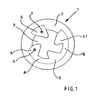
- a safety switching profile 1 which has an annular hollow profile 2 with an outer diameter of, for example, less than 1 cm.
- the safety shift profile 1 is particularly suitable for insertion into rubber profiles, which are installed, for example, in power-operated equipment, such as rolling shutters, rolling grilles, doors, lifts, working platforms and the like for protection against persons or objects that are located during a process in the path of the power-operated plant ,
- power-operated equipment such as rolling shutters, rolling grilles, doors, lifts, working platforms and the like for protection against persons or objects that are located during a process in the path of the power-operated plant .
- a switching chamber 3 is formed, in which a first switching strip 4 and a second switching strip 5 are arranged.
- the first switching strip 4 and the second switching strip 5 have an approximately triangular cross-section, and are made of an electrically conductive material, in particular a rubber material or an elastomer.
- the first switching strip 4 and the second switching strip 5 are in the hollow section 2, which is also made of a rubber material or an elastomer, but which is electrically non-conductive, made, so that in each case a triangular side is aligned approximately to the center of the switching chamber 3 ,
- the first switching strip 4 and the second switching strip 5 each have an electrically conductive switching line 6, 7 embedded from a wire, a strand of metal, carbon fiber or graphite fibers.
- the first switching strip 4 is connected via a web 8 with a first contact strip 9 and this via a further web 10 with a second contact strip 11.
- the webs 8, 9 are exactly as deep in the hollow section 2 as the switching strips 4, 5 and the contact strips 9, 11 embedded, so that the wall thickness of the hollow section 2 in the areas with and without webs 8, 9 is the same.
- the contact strips 9, 11 and the webs 8, 10 are preferably made of the same electrically conductive material as the first switching strip 4 and the second switching strip 5.
- the switching strips 4, 5 are arranged distributed symmetrically on the inner circumference of the hollow profile 2 together with the contact strips 9, 11.
Landscapes
- Push-Button Switches (AREA)
Description
- Die Erfindung betrifft eine Sicherheitsschalteinrichtung, insbesondere für kraftbetätige Anlagen, wie Rolltore, Rollgitter, Türen, Hebe-, Arbeitsbühnen und dergleichen, aufweisend eine in einem strangartigen Hohlprofil ausgebildete Schaltkammer mit zumindest zwei gegeneinander isolierten und jeweils eine elektrisch leitende Schaltleitung aufnehmenden elektrisch leitenden Schaltleisten, die bei einer gegenseitigen Berührung ein Schaltsignal auslösen, wobei die erste Schaltleiste mit zumindest einer elektrisch leitenden Kontaktleiste verbunden ist, und wobei die Kontaktleiste parallel und beabstandet zu der ersten Schaltleiste angeordnet ist.
- Eine derartige gattungsgemäße Sicherheitsschalteinrichtung ist aus der
DE 10 2005 028 739 B3 bekannt. Dieses Dokument offenbart eine Sicherheitsschalteinrichtung mit einem äußeren strangartigen Hohlprofil, in das ein erster Kontaktabschnitt mit einem leitfähigen Schaltvorsprung sowie ein zweiter Kontaktabschnitt mit einem leitfähigen Schaltvorsprung eingesetzt sind. Die leitfähigen Kontaktabschnitte und Schaltvorsprünge bilden innerhalb des Hohlraums einen S-förmigen, einen U-förmigen oder einen zahnförmigen Schaltraum und weisen dementsprechend aufwändige, beispielsweise schlangenförmige Ausgestaltungen auf. Weiterhin sind die Kontaktabschnitte allesamt das rohrförmige Hohlprofil eingesetzt. - Die
EP 1 310 624 A2 offenbart eine Sicherheitsschalteinrichtung mit einem Schließkantensicherheitsprofil, aufweisend einen Innenkörper mit wulstförmigen Vorsprüngen, dem auf einer gegenüberliegenden Längsseite der Sicherheitsschalteinrichtung ein Mantelkörper mit leistenartigen Erhebungen gegenüberliegt. Der Innenkörper und der Mantelkörper sind jeweils in das Schließkantensicherheitsprofil eingelassen. Der sich seitlich über den aufgesetzten wulstförmigen Vorsprung hinaus erstreckende Innenkörper ist notwendig, damit die gegenüberliegenden leistenförmigen Erhebungen bei einer Verformung des Schließkantensicherheitsprofils auf den in den Körper zur Auslösung eines Schaltkontakts auftreffen. - Die
EP 0 935 268 A2 beschreibt eine Sicherheitsschalteinrichtung mit einem mantelförmigen Hohlprofil, in das zwei gegenüberliegende Schaltleisten angeordnet sind. Zusätzlich sind eigenständige Kontaktleisten in dem Hohlprofil angeordnet. - Die
EP 0 866 201 A1 offenbart eine Sicherheitsschalteinrichtung, die einen ersten, angenähert ringförmig mit Vorsprüngen ausgebildeten Schaltkörper aufweist, in den ein klöppelförmiger zweiter Schaltkörper isoliert über einen Rippenkörper eingesetzt ist. Die so gebildete Sicherheitsschalteinrichtung wird anschließend in ein nicht dargestelltes Hohlprofil eingesetzt. - Der Erfindung liegt die Aufgabe zugrunde, eine gattungsgemäße Sicherheitsschalteinrichtung bereitzustellen, bei der eine zuverlässige Kontaktnahme aus allen Richtungen möglich ist und die besonders flexibel ist.
- Diese Aufgabe wird dadurch gelöst, dass die Schaltleisten und die zumindest eine Kontaktleiste eine zumindest angenähert dreieckige Querschnittskontur aufweisen, dass die Schaltleisten und die zumindest eine Kontaktleiste mit jeweils einer Dreiecksseite in das Hohlprofil eingebettet sind, dass die erste Schaltleiste mittels zumindest eines Steges mit der zumindest einen Kontaktleiste verbunden ist, dass der zumindest eine Steg zumindest teilweise in das Hohlprofil eingebettet ist, und dass die Tiefe der Einbettung der Stege der Tiefe der Einbettung der Leisten entspricht. Dabei sind nur in die vorzugsweise zwei Schaltleisten jeweils eine Schaltleitung eingesetzt, während die zumindest eine Kontaktleiste ohne Schaltleitung ausgebildet ist. In einer allgemeinsten Ausführung sind folglich zwei Schaltleisten und eine Kontaktleiste in dem Hohlprofil verteilt angeordnet. Dadurch ist die Sicherheitsschalteinrichtung einerseits sehr flexibel und kann problemlos an beispielsweise beliebig gebogenen Anlagen montiert werden, während eine Kontaktnahme aus allen Richtungen möglich und sichergestellt ist. Bevorzugt weisen die Schaltleisten und die zumindest eine Kontaktleiste mit einer Dreiecksseite in den mittleren Bereich der Schaltkammer auf. Dabei ist die Ausrichtung dieser Dreiecksseiten gleichmäßig versetzt zu der Mittellinie durch das Hohlprofil. Dabei beträgt der Winkel der Versetzung bevorzugt zwischen 5° und 25°, ganz bevorzugt ca. 15°. Durch diese außermittige Ausrichtung wirken bei einer (Schalt-) Verformung des Hohlprofils (normalerweise) Seitenflächen der Leisten zusammen, wodurch eine großflächige Kontaktfläche für eine zuverlässige Schaltkontaktauslösung gewährleistet ist. Schließlich ist insbesondere die in den mittleren Bereich ausgerichtete Dreiecksseite abgerundet ausgebildet. Die angegebene Querschnittskontur und Ausrichtung ist bei allen Leisten gleich ausgebildet, wodurch eine gute Kontaktnahme und eine hohe Flexibilität gewährleistet sind. Dabei sind die Schaltleisten und die zumindest eine Kontaktleiste jeweils mit gleichen Abständen zueinander in dem Hohlprofil verteilt angeordnet. Auch diese Ausgestaltung trägt zu einer guten Kontaktnahme und einer hohen Flexibilität bei. Die Tiefe der Einbettung in dem Hohlprofil beträgt bis angenähert einem Drittel der Gesamthöhe einer Schaltleiste oder Kontaktleiste, während die Tiefe der Einbettung in dem Hohlprofil bis angenähert der Hälfte der Dicke des Hohlprofils beträgt. Das Hohlprofil weist im Übrigen eine Wanddicke auf, die etwa 15% bis 25%, ganz bevorzugt etwa 20% des Durchmessers des Hohlprofils entspricht Die Länge einer Dreiecksseite beträgt etwa 20% bis 40%, ganz bevorzugt etwa 30% des Durchmessers des Hohlprofils auf. Dadurch, dass die erste Schaltleiste mittels zumindest eines Steges mit der zumindest einen Kontaktleiste verbunden ist, ist gewährleistet, dass ein zuverlässiger elektrischer Kontakt zwischen der Schaltleiste und der Kontaktleiste besteht, während die Flexibilität durch den Steg nicht oder nicht nachteilig beeinträchtigt ist. Der Steg kann durchgehend entlang der gesamten Länge der Sicherheitsschalteinrichtung oder aber auch abschnittsweise vorhanden sein. Schließlich ist der zumindest eine Steg zumindest teilweise in das Hohlprofil eingebettet und verbindet somit die Schaltleiste und die Kontaktleiste an der jeweils in das Hohlprofil eingebetteten Grundfläche. Die Tiefe der Einbettung des Stegs entspricht dabei der Tiefe der Einbettung der Leisten. Bevorzugt ist der Steg vollständig in das Hohlprofil eingebettet, so dass die Wanddicke des Hohlprofils in dem Bereich ohne Steg gleich der Wanddicke des Hohlprofils in dem Bereich mit Steg ist.
- In Weiterbildung der Erfindung ist die erste Schaltleiste mit zwei parallel zu der ersten und zweiten Schaltleiste angeordneten Kontaktleisten verbunden. Hierbei können die Kontaktleisten beide auf einer Seite der Schaltleiste oder aber beidseits der Schaltleiste angeordnet sein. Es ist aber im Rahmen der Erfindung auch möglich, sowohl die erste Schaltleiste als auch die zweite Schaltleiste mit jeweils einer Kontaktleiste zu verbinden. Dabei kann die Anordnung und Ausrichtung der Schaltleisten und Kontaktleisten beliebig sein. weiterhin können auch mehr als zwei Kontaktleisten mit einer Schaltleiste verbunden sein. Beispielsweise ist es möglich auf jeder Seite einer Schaltleiste zwei Kontaktleisten anzuordnen und mit dieser zu verbinden.
- In weiterer Ausgestaltung der Erfindung ist aber die zweite Schaltleiste eigenständig ohne Verbindung mit einer Kontaktleiste ausgebildet. Diese Ausführung ist die bevorzugte Ausgestaltung.
- In weiterer Ausbildung der Erfindung ist das Hohlprofil ringförmig ausgebildet. Die ringförmige Ausbildung trägt zu einer guten Kontaktname und hohen Flexibilität bei. Grundsätzlich kann das Hohlprofil aber auch elliptisch, rechteckig oder vieleckig ausgebildet sein.
- In Weiterbildung der Erfindung sind die Schaltleisten unter Einbettung der Schaltleitungen und die zumindest eine Kontaktleiste zusammen mit dem Hohlprofil aus einem extrudierbaren Material, insbesondere Gummi, Elastomeren oder Polymeren, vorzugsweise als endloses Profil hergestellt. Dadurch entsteht ein homogenes Profil.
- In weiterer Ausgestaltung ist die Schaltleitung ein elektrisch leitender Draht oder eine elektrisch leitende Litze aus Metall, beispielsweise Kupfer, Kohlefasern oder Grafitfasern. Wichtig sind eine hohe Flexibilität der Schaltleitung und eine zuverlässige Beständigkeit gegenüber Bruch durch Verbiegung. Beispielsweise hat sich ein Durchmesser des Drahts oder der Litze von bis zu einem halben Millimeter als ausreichend dimensioniert erwiesen.
- Weitere vorteilhafte Ausgestaltungen der Erfindung sind der Zeichnungsbeschreibung zu entnehmen, in der in der Figur dargestelltes Ausführungsbeispiel der Erfindung näher beschrieben ist.
- Es zeigen:
- Fig.1
- einen Schnitt durch eine Sicherheitsschalteinrichtung.
- In
Figur 1 ist ein Sicherheitsschaltprofil 1 dargestellt, das ein ringförmiges Hohlprofil 2 mit einem Außendurchmesser von beispielsweise weniger als 1 cm aufweist. Das Sicherheitsschaltprofil 1 eignet sich besonders zum Einschieben in Gummiprofile, die beispielsweise bei kraftbetätigten Anlagen, wie Rolltore, Rollgitter, Türen, Hebebühnen, Arbeitsbühnen und dergleichen zur Absicherung gegenüber Personen oder Objekten, die sich während eines Verfahrens in dem Verfahrensweg der kraftbetätigten Anlage befinden verbaut werden. Durch ein Auftreffen des Gummiprofils auf einen Körperteil einer Person oder auf ein Objekt, wird das Sicherheitsschaltprofil 1 in dem Gummiprofil so verformt, dass zwei in dem Gehäuse 2 angeordnete Schaltelemente in Kontakt kommen und dadurch in einer angeschlossenen Sicherheitsschalteinrichtung ein Schaltimpuls ausgelöst wird, der die Bewegung der Anlage beispielsweise stoppt. - In dem Hohlprofil 2 des Sicherheitsschaltprofils 1 ist eine Schaltkammer 3 ausgebildet, in der eine erste Schaltleiste 4 und eine zweite Schaltleiste 5 angeordnet sind. Die erste Schaltleiste 4 und die zweite Schaltleiste 5 weisen einen angenähert dreieckigen Querschnitt auf, und sind aus einem elektrisch leitenden Material, insbesondere einem Gummimaterial oder einen Elastomer gefertigt. Die erste Schaltleiste 4 und die zweite Schaltleiste 5 sind in das Hohlprofil 2, das ebenfalls aus einem Gummimaterial oder einem Elastomer, das aber elektrisch nicht leitend ist, gefertigt ist, so eingelassen, dass jeweils eine Dreiecksseite angenähert zu der Mitte der Schaltkammer 3 ausgerichtet ist. In die erste Schaltleiste 4 und die zweite Schaltleiste 5 ist jeweils eine elektrisch leitende Schaltleitung 6, 7 aus einem Draht, einer Litze aus Metall, Kohlefaser oder Grafitfasern eingebettet.
- Die erste Schaltleiste 4 ist über einen Steg 8 mit einer ersten Kontaktleiste 9 und diese über einen weiteren Steg 10 mit einer zweiten Kontaktleiste 11 verbunden. Die Stege 8, 9 sind genau so tief in das Hohlprofil 2 wie die Schaltleisten 4, 5 sowie die Kontaktleisten 9, 11 eingelassen, so dass die Wanddicke des Hohlprofils 2 in den Bereichen mit und ohne Stege 8, 9 gleich ist. Die Kontaktleisten 9, 11 und die Stege 8, 10 sind vorzugsweise aus dem gleichen elektrisch leitenden Material wie die erste Schaltleiste 4 und die zweite Schaltleiste 5 gefertigt. Die Schaltleisten 4, 5 sind zusammen mit den Kontaktleisten 9, 11 symmetrisch auf dem Innenumfang des Hohlprofils 2 verteilt angeordnet.
-
- 1
- Sicherheitsschalteinrichtung
- 2
- Hohlprofil
- 3
- Schaltkammer
- 4
- erste Schaltleiste
- 5
- zweite Schaltleiste
- 6
- Schaltleitung
- 7
- Schaltleitung
- 8
- Steg
- 9
- Kontaktleiste
- 10
- Steg
- 11
- Kontaktleiste
Claims (6)
- Sicherheitsschalteinrichtung (1), insbesondere für kraftbetätige Anlagen, wie Rolltore, Rollgitter, Türen, Hebe-, Arbeitsbühnen und dergleichen, aufweisend eine in einem strangartigen Hohlprofil (2) ausgebildete Schaltkammer (3) mit zumindest zwei gegeneinander isolierten und jeweils eine elektrisch leitende Schaltleitung (6, 7) aufnehmenden elektrisch leitenden Schaltleisten (4, 5), die bei einer gegenseitigen Berührung ein Schaltsignal auslösen, wobei die erste Schaltleiste (4) mit zumindest einer elektrisch leitenden Kontaktleiste (9) verbunden ist, und wobei die Kontaktleiste (9) parallel und beabstandet zu der ersten Schaltleiste (4) und der zweiten Schaltleiste (5) angeordnet ist,
dadurch gekennzeichnet, dass die Schaltleisten (4, 5) und die zumindest eine Kontaktleiste (9, 11) eine zumindest angenähert dreieckige Querschnittskontur aufweisen, dass die Schaltleisten (4, 5) und die zumindest eine Kontaktleiste (9, 11) mit jeweils einer Dreiecksseite in das Hohlprofil (2) eingebettet sind, dass die erste Schaltleiste (4) mittels zumindest eines Steges (8, 10) mit der zumindest einen Kontaktleiste (9, 11) verbunden ist, dass der zumindest eine Steg (8, 10) zumindest teilweise in das Hohlprofil (2) eingebettet ist und dass die Tiefe der Einbettung der Stege (8, 10) der Tiefe der Einbettung der Leisten (4, 5, 9, 11) entspricht. - Sicherheitsschalteinrichtung (1) nach Anspruch 1,
dadurch gekennzeichnet, dass die erste Schaltleiste (4) mit zwei parallel zu der ersten Schaltleiste (4) und zweiten Schaltleiste (5) angeordneten Kontaktleisten (9, 11) verbunden ist. - Sicherheitsschalteinrichtung (1) nach Anspruch 1 oder 2,
dadurch gekennzeichnet, dass die zweite Schaltleiste (5) mit zumindest einer Kontaktleiste (9, 11) verbunden ist. - Sicherheitsschalteinrichtung (1) nach einem der vorherigen Ansprüche,
dadurch gekennzeichnet, dass die Hohlprofil (2) einen ringförmigen Querschnitt aufweist. - Sicherheitsschalteinrichtung (1) nach einem der vorherigen Ansprüche,
dadurch gekennzeichnet, dass die Schaltleisten (4, 5) unter Einbettung der Schaltleitungen (6, 7) und die zumindest eine Kontaktleiste (9, 11) zusammen mit dem Hohlprofil (2) aus einem extrudierbaren Material, insbesondere Gummi oder Polymeren, vorzugsweise als endloses Profil hergestellt sind. - Sicherheitsschalteinrichtung (1) nach einem der vorherigen Ansprüche,
dadurch gekennzeichnet, dass die Schaltleitung (6, 7) ein elektrisch leitender Draht oder eine elektrisch leitende Litze aus Metall, Kohlefasern oder Grafitfasern ist.
Priority Applications (1)
| Application Number | Priority Date | Filing Date | Title |
|---|---|---|---|
| PL13153269T PL2631926T3 (pl) | 2012-02-22 | 2013-01-30 | Urządzenie przełącznika bezpieczeństwa |
Applications Claiming Priority (1)
| Application Number | Priority Date | Filing Date | Title |
|---|---|---|---|
| DE102012003382A DE102012003382A1 (de) | 2012-02-22 | 2012-02-22 | Sicherheitsschalteinrichtung |
Publications (2)
| Publication Number | Publication Date |
|---|---|
| EP2631926A1 EP2631926A1 (de) | 2013-08-28 |
| EP2631926B1 true EP2631926B1 (de) | 2015-12-30 |
Family
ID=47681721
Family Applications (1)
| Application Number | Title | Priority Date | Filing Date |
|---|---|---|---|
| EP13153269.9A Active EP2631926B1 (de) | 2012-02-22 | 2013-01-30 | Sicherheitsschalteinrichtung |
Country Status (5)
| Country | Link |
|---|---|
| EP (1) | EP2631926B1 (de) |
| DE (1) | DE102012003382A1 (de) |
| DK (1) | DK2631926T3 (de) |
| ES (1) | ES2564755T3 (de) |
| PL (1) | PL2631926T3 (de) |
Family Cites Families (7)
| Publication number | Priority date | Publication date | Assignee | Title |
|---|---|---|---|---|
| GB465069A (en) | 1935-11-02 | 1937-04-30 | Stanley Saunders | Improvements in or relating to electric contact making devices |
| DE19602744C2 (de) * | 1996-01-19 | 1999-04-29 | Mayser Gmbh & Co | Sicherheitsschaltleistenanordnung |
| DE19711600A1 (de) * | 1997-03-20 | 1998-09-24 | Karlheinz Beckhausen | Sicherheitskontaktelement |
| EP0935268A3 (de) * | 1998-02-09 | 2000-09-06 | Shinmei Rubber Ind. Co., Ltd. | Omnidirektioneller Kabelschalter |
| DE19846081A1 (de) | 1998-10-07 | 2000-04-13 | Karlheinz Beckhausen | Sicherheitskontaktschiene oder Sicherheitskontaktelement |
| DE10155466A1 (de) * | 2001-11-12 | 2003-05-22 | Karlheinz Beckhausen | Schließkantensicherheitsprofil |
| DE102005028739C5 (de) * | 2005-06-21 | 2012-08-16 | Metzeler Automotive Profile Systems Gmbh | Schaltleiste, insbesondere als Einklemmschutz für ein Kraftfahrzeug |
-
2012
- 2012-02-22 DE DE102012003382A patent/DE102012003382A1/de not_active Withdrawn
-
2013
- 2013-01-30 ES ES13153269.9T patent/ES2564755T3/es active Active
- 2013-01-30 PL PL13153269T patent/PL2631926T3/pl unknown
- 2013-01-30 EP EP13153269.9A patent/EP2631926B1/de active Active
- 2013-01-30 DK DK13153269.9T patent/DK2631926T3/en active
Also Published As
| Publication number | Publication date |
|---|---|
| DE102012003382A1 (de) | 2013-08-22 |
| ES2564755T3 (es) | 2016-03-28 |
| PL2631926T3 (pl) | 2016-06-30 |
| EP2631926A1 (de) | 2013-08-28 |
| DK2631926T3 (en) | 2016-03-14 |
Similar Documents
| Publication | Publication Date | Title |
|---|---|---|
| EP2862244B1 (de) | Verbindungselement für eine schleifleitung, schleifleitung und verfahren zur herstellung einer schleifleitung | |
| DE68913597T2 (de) | Lötfreier elektrischer Steckverbinder. | |
| EP3717391B1 (de) | Anschlusselement zum elektrischen kontaktieren von zugträgern in einem lasttragfähigen riemen für eine aufzuganlage sowie verfahren zum montieren des anschlusselements an dem riemen | |
| EP1892731B1 (de) | Kabel und Verfahren zur Herstellung des Kabels | |
| EP2631926B1 (de) | Sicherheitsschalteinrichtung | |
| EP3433198B1 (de) | Aufzuganlage mit von einem elektrisch leitfähigen gehäuse teilweise umgebenem tragmittel, insbesondere an einer umlenkrollenanordnung | |
| DE102019104883B4 (de) | Elektrische Heizvorrichtung | |
| DE102004026458A1 (de) | Überwachungseinrichtung für flexible Heizelemente | |
| EP1451497A1 (de) | Kunststoffschlauch, insbesondere pneumatikschlauch | |
| EP2337161B1 (de) | Steckeranordnung und Abdichteinrichtung für wenigstens eine, insbesondere elektrische Leitung | |
| WO2019052909A1 (de) | Verfahren zum elektrischen anbinden eines anschlusselements an einen riemen für eine aufzuganlage sowie entsprechende riemenanordnung | |
| WO2013131605A1 (de) | Kabelverbindungsbauteil zum verbinden des endes eines kabels mit dem oder den enden eines oder mehrerer anderer kabel | |
| EP3182519A1 (de) | Leiterklemmvorrichtung | |
| EP2609608B1 (de) | Elektrischer anschluss einer sicherheitsschalteinrichtung | |
| DE102015104629B4 (de) | Klemmfeder für eine Leiteranschlussklemme und Leiteranschlussklemme mit entsprechender Klemmfeder | |
| DE102014117949B4 (de) | Kontaktmodul mit Klemmeinrichtung | |
| DE202017102097U1 (de) | Keilelement für eine Seilterminalanordnung | |
| EP0396927B1 (de) | Anschluss- bzw. Verbindungselement für Kabelbäume | |
| EP3857584B1 (de) | Stecker für ein sicherheitsprofil und eine schaltleiste | |
| DE202013100223U1 (de) | Verbindungselement für eine Schleifleitung, Bausatz für eine Schleifleitung und Schleifleitung | |
| DE2309018A1 (de) | Mehrschichten-betonplatte | |
| DE69923777T2 (de) | Flexible Verbindungsanordnung | |
| DE102005005917A1 (de) | Anschlussklemme für einen isolierten elektrischen Leiter | |
| DE3920723A1 (de) | Als profilkoerper ausgebildeter sensor | |
| DE102017127439B4 (de) | Elektrische Buchse mit Toleranzausgleich |
Legal Events
| Date | Code | Title | Description |
|---|---|---|---|
| PUAI | Public reference made under article 153(3) epc to a published international application that has entered the european phase |
Free format text: ORIGINAL CODE: 0009012 |
|
| AK | Designated contracting states |
Kind code of ref document: A1 Designated state(s): AL AT BE BG CH CY CZ DE DK EE ES FI FR GB GR HR HU IE IS IT LI LT LU LV MC MK MT NL NO PL PT RO RS SE SI SK SM TR |
|
| AX | Request for extension of the european patent |
Extension state: BA ME |
|
| 17P | Request for examination filed |
Effective date: 20140116 |
|
| RBV | Designated contracting states (corrected) |
Designated state(s): AL AT BE BG CH CY CZ DE DK EE ES FI FR GB GR HR HU IE IS IT LI LT LU LV MC MK MT NL NO PL PT RO RS SE SI SK SM TR |
|
| GRAP | Despatch of communication of intention to grant a patent |
Free format text: ORIGINAL CODE: EPIDOSNIGR1 |
|
| INTG | Intention to grant announced |
Effective date: 20150629 |
|
| GRAR | Information related to intention to grant a patent recorded |
Free format text: ORIGINAL CODE: EPIDOSNIGR71 |
|
| GRAS | Grant fee paid |
Free format text: ORIGINAL CODE: EPIDOSNIGR3 |
|
| RAP1 | Party data changed (applicant data changed or rights of an application transferred) |
Owner name: MENZ, JUERGEN |
|
| RIN1 | Information on inventor provided before grant (corrected) |
Inventor name: MENZ, JUERGEN |
|
| GRAA | (expected) grant |
Free format text: ORIGINAL CODE: 0009210 |
|
| INTG | Intention to grant announced |
Effective date: 20151027 |
|
| AK | Designated contracting states |
Kind code of ref document: B1 Designated state(s): AL AT BE BG CH CY CZ DE DK EE ES FI FR GB GR HR HU IE IS IT LI LT LU LV MC MK MT NL NO PL PT RO RS SE SI SK SM TR |
|
| REG | Reference to a national code |
Ref country code: GB Ref legal event code: FG4D Free format text: NOT ENGLISH |
|
| REG | Reference to a national code |
Ref country code: CH Ref legal event code: EP |
|
| REG | Reference to a national code |
Ref country code: AT Ref legal event code: REF Ref document number: 767814 Country of ref document: AT Kind code of ref document: T Effective date: 20160115 |
|
| REG | Reference to a national code |
Ref country code: IE Ref legal event code: FG4D Free format text: LANGUAGE OF EP DOCUMENT: GERMAN |
|
| REG | Reference to a national code |
Ref country code: DE Ref legal event code: R096 Ref document number: 502013001673 Country of ref document: DE |
|
| REG | Reference to a national code |
Ref country code: FR Ref legal event code: PLFP Year of fee payment: 4 |
|
| REG | Reference to a national code |
Ref country code: DK Ref legal event code: T3 Effective date: 20160311 |
|
| REG | Reference to a national code |
Ref country code: ES Ref legal event code: FG2A Ref document number: 2564755 Country of ref document: ES Kind code of ref document: T3 Effective date: 20160328 |
|
| REG | Reference to a national code |
Ref country code: SE Ref legal event code: TRGR |
|
| REG | Reference to a national code |
Ref country code: NL Ref legal event code: FP |
|
| REG | Reference to a national code |
Ref country code: LT Ref legal event code: MG4D |
|
| PG25 | Lapsed in a contracting state [announced via postgrant information from national office to epo] |
Ref country code: NO Free format text: LAPSE BECAUSE OF FAILURE TO SUBMIT A TRANSLATION OF THE DESCRIPTION OR TO PAY THE FEE WITHIN THE PRESCRIBED TIME-LIMIT Effective date: 20160330 Ref country code: LT Free format text: LAPSE BECAUSE OF FAILURE TO SUBMIT A TRANSLATION OF THE DESCRIPTION OR TO PAY THE FEE WITHIN THE PRESCRIBED TIME-LIMIT Effective date: 20151230 Ref country code: HR Free format text: LAPSE BECAUSE OF FAILURE TO SUBMIT A TRANSLATION OF THE DESCRIPTION OR TO PAY THE FEE WITHIN THE PRESCRIBED TIME-LIMIT Effective date: 20151230 |
|
| PG25 | Lapsed in a contracting state [announced via postgrant information from national office to epo] |
Ref country code: LV Free format text: LAPSE BECAUSE OF FAILURE TO SUBMIT A TRANSLATION OF THE DESCRIPTION OR TO PAY THE FEE WITHIN THE PRESCRIBED TIME-LIMIT Effective date: 20151230 Ref country code: RS Free format text: LAPSE BECAUSE OF FAILURE TO SUBMIT A TRANSLATION OF THE DESCRIPTION OR TO PAY THE FEE WITHIN THE PRESCRIBED TIME-LIMIT Effective date: 20151230 Ref country code: FI Free format text: LAPSE BECAUSE OF FAILURE TO SUBMIT A TRANSLATION OF THE DESCRIPTION OR TO PAY THE FEE WITHIN THE PRESCRIBED TIME-LIMIT Effective date: 20151230 |
|
| REG | Reference to a national code |
Ref country code: GR Ref legal event code: EP Ref document number: 20160400552 Country of ref document: GR Effective date: 20160505 |
|
| PG25 | Lapsed in a contracting state [announced via postgrant information from national office to epo] |
Ref country code: CZ Free format text: LAPSE BECAUSE OF FAILURE TO SUBMIT A TRANSLATION OF THE DESCRIPTION OR TO PAY THE FEE WITHIN THE PRESCRIBED TIME-LIMIT Effective date: 20151230 |
|
| PG25 | Lapsed in a contracting state [announced via postgrant information from national office to epo] |
Ref country code: RO Free format text: LAPSE BECAUSE OF FAILURE TO SUBMIT A TRANSLATION OF THE DESCRIPTION OR TO PAY THE FEE WITHIN THE PRESCRIBED TIME-LIMIT Effective date: 20151230 Ref country code: IS Free format text: LAPSE BECAUSE OF FAILURE TO SUBMIT A TRANSLATION OF THE DESCRIPTION OR TO PAY THE FEE WITHIN THE PRESCRIBED TIME-LIMIT Effective date: 20160430 Ref country code: SK Free format text: LAPSE BECAUSE OF FAILURE TO SUBMIT A TRANSLATION OF THE DESCRIPTION OR TO PAY THE FEE WITHIN THE PRESCRIBED TIME-LIMIT Effective date: 20151230 Ref country code: SM Free format text: LAPSE BECAUSE OF FAILURE TO SUBMIT A TRANSLATION OF THE DESCRIPTION OR TO PAY THE FEE WITHIN THE PRESCRIBED TIME-LIMIT Effective date: 20151230 Ref country code: EE Free format text: LAPSE BECAUSE OF FAILURE TO SUBMIT A TRANSLATION OF THE DESCRIPTION OR TO PAY THE FEE WITHIN THE PRESCRIBED TIME-LIMIT Effective date: 20151230 Ref country code: LU Free format text: LAPSE BECAUSE OF FAILURE TO SUBMIT A TRANSLATION OF THE DESCRIPTION OR TO PAY THE FEE WITHIN THE PRESCRIBED TIME-LIMIT Effective date: 20160130 |
|
| PG25 | Lapsed in a contracting state [announced via postgrant information from national office to epo] |
Ref country code: MC Free format text: LAPSE BECAUSE OF FAILURE TO SUBMIT A TRANSLATION OF THE DESCRIPTION OR TO PAY THE FEE WITHIN THE PRESCRIBED TIME-LIMIT Effective date: 20151230 |
|
| REG | Reference to a national code |
Ref country code: DE Ref legal event code: R097 Ref document number: 502013001673 Country of ref document: DE |
|
| REG | Reference to a national code |
Ref country code: IE Ref legal event code: MM4A |
|
| PLBE | No opposition filed within time limit |
Free format text: ORIGINAL CODE: 0009261 |
|
| STAA | Information on the status of an ep patent application or granted ep patent |
Free format text: STATUS: NO OPPOSITION FILED WITHIN TIME LIMIT |
|
| 26N | No opposition filed |
Effective date: 20161003 |
|
| REG | Reference to a national code |
Ref country code: FR Ref legal event code: PLFP Year of fee payment: 5 |
|
| PG25 | Lapsed in a contracting state [announced via postgrant information from national office to epo] |
Ref country code: IE Free format text: LAPSE BECAUSE OF NON-PAYMENT OF DUE FEES Effective date: 20160130 |
|
| PG25 | Lapsed in a contracting state [announced via postgrant information from national office to epo] |
Ref country code: SI Free format text: LAPSE BECAUSE OF FAILURE TO SUBMIT A TRANSLATION OF THE DESCRIPTION OR TO PAY THE FEE WITHIN THE PRESCRIBED TIME-LIMIT Effective date: 20151230 |
|
| PG25 | Lapsed in a contracting state [announced via postgrant information from national office to epo] |
Ref country code: MT Free format text: LAPSE BECAUSE OF FAILURE TO SUBMIT A TRANSLATION OF THE DESCRIPTION OR TO PAY THE FEE WITHIN THE PRESCRIBED TIME-LIMIT Effective date: 20151230 |
|
| REG | Reference to a national code |
Ref country code: FR Ref legal event code: PLFP Year of fee payment: 6 |
|
| PG25 | Lapsed in a contracting state [announced via postgrant information from national office to epo] |
Ref country code: CY Free format text: LAPSE BECAUSE OF FAILURE TO SUBMIT A TRANSLATION OF THE DESCRIPTION OR TO PAY THE FEE WITHIN THE PRESCRIBED TIME-LIMIT Effective date: 20151230 Ref country code: HU Free format text: LAPSE BECAUSE OF FAILURE TO SUBMIT A TRANSLATION OF THE DESCRIPTION OR TO PAY THE FEE WITHIN THE PRESCRIBED TIME-LIMIT; INVALID AB INITIO Effective date: 20130130 |
|
| PG25 | Lapsed in a contracting state [announced via postgrant information from national office to epo] |
Ref country code: MK Free format text: LAPSE BECAUSE OF FAILURE TO SUBMIT A TRANSLATION OF THE DESCRIPTION OR TO PAY THE FEE WITHIN THE PRESCRIBED TIME-LIMIT Effective date: 20151230 Ref country code: PT Free format text: LAPSE BECAUSE OF FAILURE TO SUBMIT A TRANSLATION OF THE DESCRIPTION OR TO PAY THE FEE WITHIN THE PRESCRIBED TIME-LIMIT Effective date: 20151230 Ref country code: TR Free format text: LAPSE BECAUSE OF FAILURE TO SUBMIT A TRANSLATION OF THE DESCRIPTION OR TO PAY THE FEE WITHIN THE PRESCRIBED TIME-LIMIT Effective date: 20151230 |
|
| PG25 | Lapsed in a contracting state [announced via postgrant information from national office to epo] |
Ref country code: BG Free format text: LAPSE BECAUSE OF FAILURE TO SUBMIT A TRANSLATION OF THE DESCRIPTION OR TO PAY THE FEE WITHIN THE PRESCRIBED TIME-LIMIT Effective date: 20151230 |
|
| PG25 | Lapsed in a contracting state [announced via postgrant information from national office to epo] |
Ref country code: AL Free format text: LAPSE BECAUSE OF FAILURE TO SUBMIT A TRANSLATION OF THE DESCRIPTION OR TO PAY THE FEE WITHIN THE PRESCRIBED TIME-LIMIT Effective date: 20151230 |
|
| REG | Reference to a national code |
Ref country code: DE Ref legal event code: R082 Ref document number: 502013001673 Country of ref document: DE Representative=s name: GOSDIN, CARSTENSEN & PARTNER PATENTANWAELTE PA, DE |
|
| REG | Reference to a national code |
Ref country code: CH Ref legal event code: U11 Free format text: ST27 STATUS EVENT CODE: U-0-0-U10-U11 (AS PROVIDED BY THE NATIONAL OFFICE) Effective date: 20260201 |
|
| PGFP | Annual fee paid to national office [announced via postgrant information from national office to epo] |
Ref country code: NL Payment date: 20260121 Year of fee payment: 14 |
|
| PGFP | Annual fee paid to national office [announced via postgrant information from national office to epo] |
Ref country code: SE Payment date: 20260121 Year of fee payment: 14 |
|
| PGFP | Annual fee paid to national office [announced via postgrant information from national office to epo] |
Ref country code: GB Payment date: 20260122 Year of fee payment: 14 |
|
| PGFP | Annual fee paid to national office [announced via postgrant information from national office to epo] |
Ref country code: ES Payment date: 20260217 Year of fee payment: 14 |
|
| PGFP | Annual fee paid to national office [announced via postgrant information from national office to epo] |
Ref country code: DK Payment date: 20260121 Year of fee payment: 14 Ref country code: DE Payment date: 20260131 Year of fee payment: 14 |
|
| PGFP | Annual fee paid to national office [announced via postgrant information from national office to epo] |
Ref country code: AT Payment date: 20260119 Year of fee payment: 14 |
|
| PGFP | Annual fee paid to national office [announced via postgrant information from national office to epo] |
Ref country code: BE Payment date: 20260121 Year of fee payment: 14 Ref country code: IT Payment date: 20260130 Year of fee payment: 14 |
|
| PGFP | Annual fee paid to national office [announced via postgrant information from national office to epo] |
Ref country code: FR Payment date: 20260128 Year of fee payment: 14 |
|
| PGFP | Annual fee paid to national office [announced via postgrant information from national office to epo] |
Ref country code: CH Payment date: 20260201 Year of fee payment: 14 |
|
| PGFP | Annual fee paid to national office [announced via postgrant information from national office to epo] |
Ref country code: GR Payment date: 20260119 Year of fee payment: 14 Ref country code: PL Payment date: 20260120 Year of fee payment: 14 |