EP2631573A2 - Haushaltgerät, insbesondere Kühlschrank, mit einem Ventilator im Innenraum - Google Patents
Haushaltgerät, insbesondere Kühlschrank, mit einem Ventilator im Innenraum Download PDFInfo
- Publication number
- EP2631573A2 EP2631573A2 EP20130000652 EP13000652A EP2631573A2 EP 2631573 A2 EP2631573 A2 EP 2631573A2 EP 20130000652 EP20130000652 EP 20130000652 EP 13000652 A EP13000652 A EP 13000652A EP 2631573 A2 EP2631573 A2 EP 2631573A2
- Authority
- EP
- European Patent Office
- Prior art keywords
- fan
- stator
- rotor
- appliance according
- domestic appliance
- Prior art date
- Legal status (The legal status is an assumption and is not a legal conclusion. Google has not performed a legal analysis and makes no representation as to the accuracy of the status listed.)
- Granted
Links
Images
Classifications
-
- F—MECHANICAL ENGINEERING; LIGHTING; HEATING; WEAPONS; BLASTING
- F25—REFRIGERATION OR COOLING; COMBINED HEATING AND REFRIGERATION SYSTEMS; HEAT PUMP SYSTEMS; MANUFACTURE OR STORAGE OF ICE; LIQUEFACTION SOLIDIFICATION OF GASES
- F25D—REFRIGERATORS; COLD ROOMS; ICE-BOXES; COOLING OR FREEZING APPARATUS NOT OTHERWISE PROVIDED FOR
- F25D17/00—Arrangements for circulating cooling fluids; Arrangements for circulating gas, e.g. air, within refrigerated spaces
- F25D17/04—Arrangements for circulating cooling fluids; Arrangements for circulating gas, e.g. air, within refrigerated spaces for circulating air, e.g. by convection
- F25D17/06—Arrangements for circulating cooling fluids; Arrangements for circulating gas, e.g. air, within refrigerated spaces for circulating air, e.g. by convection by forced circulation
- F25D17/062—Arrangements for circulating cooling fluids; Arrangements for circulating gas, e.g. air, within refrigerated spaces for circulating air, e.g. by convection by forced circulation in household refrigerators
-
- F—MECHANICAL ENGINEERING; LIGHTING; HEATING; WEAPONS; BLASTING
- F24—HEATING; RANGES; VENTILATING
- F24C—DOMESTIC STOVES OR RANGES ; DETAILS OF DOMESTIC STOVES OR RANGES, OF GENERAL APPLICATION
- F24C15/00—Details
- F24C15/32—Arrangements of ducts for hot gases, e.g. in or around baking ovens
- F24C15/322—Arrangements of ducts for hot gases, e.g. in or around baking ovens with forced circulation
-
- F—MECHANICAL ENGINEERING; LIGHTING; HEATING; WEAPONS; BLASTING
- F25—REFRIGERATION OR COOLING; COMBINED HEATING AND REFRIGERATION SYSTEMS; HEAT PUMP SYSTEMS; MANUFACTURE OR STORAGE OF ICE; LIQUEFACTION SOLIDIFICATION OF GASES
- F25D—REFRIGERATORS; COLD ROOMS; ICE-BOXES; COOLING OR FREEZING APPARATUS NOT OTHERWISE PROVIDED FOR
- F25D17/00—Arrangements for circulating cooling fluids; Arrangements for circulating gas, e.g. air, within refrigerated spaces
- F25D17/04—Arrangements for circulating cooling fluids; Arrangements for circulating gas, e.g. air, within refrigerated spaces for circulating air, e.g. by convection
- F25D17/06—Arrangements for circulating cooling fluids; Arrangements for circulating gas, e.g. air, within refrigerated spaces for circulating air, e.g. by convection by forced circulation
-
- H—ELECTRICITY
- H02—GENERATION; CONVERSION OR DISTRIBUTION OF ELECTRIC POWER
- H02K—DYNAMO-ELECTRIC MACHINES
- H02K5/00—Casings; Enclosures; Supports
- H02K5/04—Casings or enclosures characterised by the shape, form or construction thereof
- H02K5/12—Casings or enclosures characterised by the shape, form or construction thereof specially adapted for operating in liquid or gas
- H02K5/128—Casings or enclosures characterised by the shape, form or construction thereof specially adapted for operating in liquid or gas using air-gap sleeves or air-gap discs
- H02K5/1282—Casings or enclosures characterised by the shape, form or construction thereof specially adapted for operating in liquid or gas using air-gap sleeves or air-gap discs the partition wall in the air-gap being non cylindrical
-
- H—ELECTRICITY
- H02—GENERATION; CONVERSION OR DISTRIBUTION OF ELECTRIC POWER
- H02K—DYNAMO-ELECTRIC MACHINES
- H02K7/00—Arrangements for handling mechanical energy structurally associated with dynamo-electric machines, e.g. structural association with mechanical driving motors or auxiliary dynamo-electric machines
- H02K7/14—Structural association with mechanical loads, e.g. with hand-held machine tools or fans
-
- F—MECHANICAL ENGINEERING; LIGHTING; HEATING; WEAPONS; BLASTING
- F25—REFRIGERATION OR COOLING; COMBINED HEATING AND REFRIGERATION SYSTEMS; HEAT PUMP SYSTEMS; MANUFACTURE OR STORAGE OF ICE; LIQUEFACTION SOLIDIFICATION OF GASES
- F25D—REFRIGERATORS; COLD ROOMS; ICE-BOXES; COOLING OR FREEZING APPARATUS NOT OTHERWISE PROVIDED FOR
- F25D2317/00—Details or arrangements for circulating cooling fluids; Details or arrangements for circulating gas, e.g. air, within refrigerated spaces, not provided for in other groups of this subclass
- F25D2317/06—Details or arrangements for circulating cooling fluids; Details or arrangements for circulating gas, e.g. air, within refrigerated spaces, not provided for in other groups of this subclass with forced air circulation
- F25D2317/068—Details or arrangements for circulating cooling fluids; Details or arrangements for circulating gas, e.g. air, within refrigerated spaces, not provided for in other groups of this subclass with forced air circulation characterised by the fans
- F25D2317/0681—Details thereof
Definitions
- the invention relates to a domestic appliance, in particular a refrigerator, with a useful space, a useful space delimiting the useful space wall, at least one fan arranged in the useful space and comprising a drive comprising a stator and a rotor coupled to the fan, wherein the rotor is driven by the stator electromagnetically for rotation can be.
- a fan in the interior thereof.
- an electric motor is provided outside the working space.
- a stator and a rotor wherein the rotor is rotated by a field generated by the stator.
- an opening is provided m to guide a drive shaft to the fan.
- the whole fan is located with rotor and stator in the work space, with an opening in the useful space wall is necessary for the power supply and the fan body is firmly connected to the Nutzraumwand
- the stator is arranged outside the working space and the rotor within the working space. With such an arrangement, the fan can be driven through the Nutzraumwand without an opening of the Nutzraumwand is required.
- the rotor is housed within a chamber.
- the chamber can be designed so that at least a part of the chamber is movably mounted in the working space.
- the rotor may comprise one or more fan-side permanent magnets or ferrite iron cores (e) driven by the field of the stator, i. the drive can be configured as a synchronous motor.
- the rotor may also comprise a short-circuit winding and / or a metal body (e.g., a disc of aluminum) in which currents may flow with the stator, i. the drive can be designed as an asynchronous motor.
- the stator may comprise a plurality of coils which are powered by a coil drive.
- the coil drive is designed so that they Coils are supplied with mutually phase-shifted currents, so as to produce a magnetic rotating field.
- stator-side magnet has a stator-side magnet and a mechanical drive. With the drive, the stator-side magnet can be rotated so as to produce a magnetic rotating field for driving the rotor.
- the household appliance according to the invention is preferably a refrigerator.
- the invention may e.g. can also be used in a freezer, an oven, a microwave oven or a steam cooker.
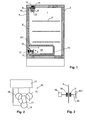
- Fig. 1 an embodiment of the invention will be described with reference to a refrigerator.
- the refrigerator has a working space 1, in which, for example, grid 2 are arranged for receiving the goods to be cooled.
- a working space 1 At the front of the utility room 1 is closed by a door 3, on the other pages, the Nutzraumcondition 4 of insulated wall elements educated.
- a cooling unit 5 In the area of the door 3 opposite the rear wall of the work space 1, a cooling unit 5 is arranged, with which the work space 1 is cooled.
- two fans 6, 7 are arranged in the work space, but only one fan or more than two fans can be provided.
- a first fan 6 is arranged by way of example in the area of the ceiling of the work space 1 and generates a flow of air running along the rear wall in order to continue the cooling from the cooling unit 5.
- the first fan 6 is rotatably mounted in a bracket 8, which in turn is held in a holder 9 on the Nutzraumwand, in such a way that the fan can be removed in a simple manner and without tools the work space to a cleaning of the area concerned enable.
- the fan 6 is connected via a shaft 10 to a rotor 11.
- a rotor 11 This is located near the utility wall, e.g. Less than 1 cm from the Nutzraumwand, but still within the Nutzraums 1.
- a stator 12 On the opposite side of the Nutzraumwand a stator 12 is provided which generates a magnetic rotating field, with which the rotor 9 can be rotated.
- the structure of the stator 12 and the rotor 9 will be described in more detail below.
- the shaft 10 may also be omitted if the rotor 11 is connected directly to the fan 6.
- the second fan 7 is located in a chamber 13.
- This chamber 13 is fixedly or removably disposed in the work space 1 and partially or completely separated from the work space via chamber walls, so that in the chamber 13 a different from the rest of the work space climate can be maintained eg with different temperature and / or humidity.
- the second fan 7 serves to move the air in the chamber 13 and in this way for a more homogeneous climate (temperature, humidity) within the chamber 13 to provide.
- the chamber 13 may e.g. at least partially formed by a removable from the use of space 1 insert 14, on which the fan 7 is arranged. In this way, the fan 7 can be removed together with the use of the device.
- the insert 14 may e.g. form an optional accessory of the device.
- the insert 14 is a drawer, which forms a separate chamber 13 from the rest of the useful space 1 in the inserted state together with the partition wall 131.
- Such a chamber can form its own climatic zone in which different climatic conditions can be maintained compared to the rest of the useful space.
- the insert 14 is preferably designed to be at least partially open, so that air can be conveyed through this side with the fan 7.
- Fig. 1 illustrates where the fan 7 at the back of the insert 14, ie the side facing away from the door 3, is open.
- the fan 7 is designed to have a (in Fig. 1 shown with arrows) generates air flow to this side, which thus run along a part of the rear wall of the working space 1 and can effect an efficient heat exchange with the same.
- the drive of the second fan 7 is the same as that of the first fan 6, i. the fan 7 is connected via a shaft 10 to a rotor 11 which is driven by a stator 12 for rotation.
- the rotor 11 consists of a body containing at least one permanent magnet (referred to in the claims as a "fan-side permanent magnet") and / or at least one ferritic iron core.
- a Permanent magnet or iron core can be driven to rotate with a suitable, time-varying magnetic field (a so-called rotating field).
- stator 12 The rotating field is generated by the stator 12.
- stator 12 In the design, the in Fig. 2 is shown, the stator 12 consists of three on a circular line concentric with the shaft 11 arranged coils 16, which are powered by a coil drive 17 with power.
- the coil drive 17 generates in a known manner three mutually phase-shifted alternating currents, which are passed through the coils.
- stator 12 may be constructed in other ways.
- An example is in Fig. 3 illustrates where the stator 12 is formed by a magnet 18, which is referred to in the claims as "stator-side magnet", and by a magnetic drive 19.
- the magnet 18 is preferably a permanent magnet with a pole direction perpendicular to the shaft 10. It can be rotated by the magnetic drive 19 about the axis of the shaft 10 and thus generates the magnetic field mentioned above.
- the magnetic drive 19 is an electric motor.
- stator is to be understood as that component which generates the magnetic field with which the rotor is driven. But the term stator does not imply that all parts of the stator are at rest.
- the rotor 11 is designed as a permanent magnet.
- the rotor 11 may also be a short-circuit winding, in which the rotating field of the stator induces a current, which in turn leads to a magnetic field which interacts with the rotating field and drives the rotor.
- the drive operates in the manner of an asynchronous AC motor.
- the Nutzraumwand 4 between the stator 12 and the rotor 11 should be permeable to the rotating field.
- it should be non-conductive to avoid eddy currents.
- it is made of plastic or, for example, for applications in an oven, ceramic or glass.
- Fig. 1 shows only two possible arrangements of the fan 6 or 7 in the working space 1.
- the fan can also be arranged at other locations of the work space 1, for example on a side wall and / or in the region of the door. 3
- the inventive design makes it possible to sell the household appliance with or without a fan, without the structural changes are necessary.
- An existing device as far as it already contains the stator, can be upgraded by simple installation of the rotor and fan.
Landscapes
- Engineering & Computer Science (AREA)
- Chemical & Material Sciences (AREA)
- Combustion & Propulsion (AREA)
- Mechanical Engineering (AREA)
- General Engineering & Computer Science (AREA)
- Power Engineering (AREA)
- Physics & Mathematics (AREA)
- Thermal Sciences (AREA)
- Structures Of Non-Positive Displacement Pumps (AREA)
- Cold Air Circulating Systems And Constructional Details In Refrigerators (AREA)
Abstract
Description
- Die Erfindung betrifft ein Haushaltsgerät, insbesondere einen Kühlschrank, mit einem Nutzraum, einer den Nutzraum begrenzenden Nutzraumwand, mindestens einem im Nutzraum angeordneten Ventilator und mit einem Antrieb umfassend einen Stator und einen mit dem Ventilator gekoppelten Rotor, wobei der Rotor vom Stator elektromagnetisch zur Rotation angetrieben werden kann.
- Um die Wirkung von Haushaltgeräten zu verbessern, wurde vorgeschlagen, in deren Innenraum einen Ventilator anzuordnen. Mit dieser Massnahme kann beispielsweise die Temperaturverteilung im Innenraum verbessert werden. Zum Antreiben des Ventilators ist ausserhalb des Nutzraums ein Elektromotor vorgesehen. Dieser besitzt in bekannter Weise einen Stator und einen Rotor, wobei der Rotor von einem vom Stator erzeugten Feld rotiert wird. In der Nutzraumwand ist eine Durchbrechung vorgesehen, m eine Antriebswelle zum Ventilator zu führen. Alternativ befindet sich der ganze Ventilator mit Rotor und Stator im Nutzraum, wobei für die Stromzufuhr eine Durchbrechung in der Nutzraumwand notwendig ist und der Ventilatorkörper fest mit der Nutzraumwand verbunden ist
- Eine derartige Lösung, und insbesondere die Durchbrechung in der Nutzraumwand, wird jedoch als nachteilig empfunden, weil die Reinigung des Nutzraums erschwert wird und weil eine ausreichend dichte Durchführung im Bereich der Durchbrechung aufwändig ist.
- Es stellt sich deshalb die Aufgabe, ein Haushaltsgerät der eingangs genannten Art bereitzustellen, das diese Nachteile mindestens teilweise vermeidet.
- Diese Aufgabe wird vom Haushaltsgerät gemäss Anspruch 1 gelöst. Demgemäss ist der Stator ausserhalb des Nutzraums und der Rotor innerhalb des Nutzraums angeordnet. Mit einer solchen Anordnung kann der Ventilator durch die Nutzraumwand angetrieben werden, ohne dass eine Durchbrechung der Nutzraumwand erforderlich ist.
- In einer bevorzugten Variante der Erfindung ist der Rotor innerhalb einer Kammer untergebracht. Die Kammer kann dabei so ausgestaltet sein, dass zumindest ein Teil der Kammer im Nutzraum beweglich gelagert ist.
- Der Rotor kann einen oder mehrere ventilatorseitigen Permanentmagneten oder ferritische Eisenkern(e) aufweisen, der vom Feld des Stators angetrieben wird, d.h. der Antrieb kann als Synchronmotor ausgestaltet sein. Der Rotor kann jedoch auch eine Kurzschlusswicklung und/oder einen Metallkörper (z.B. Scheibe aus Aluminium) aufweisen, in welcher bzw. welchem mit dem Stator Ströme werden können, d.h. der Antrieb kann als Asynchronmotor ausgestaltet sein.
- Der Stator kann mehrere Spulen umfassen, die von einer Spulenansteuerung mit Strom versorgt werden. Die Spulenansteuerung ist so ausgestaltet, dass sie die Spulen mit zueinander phasenverschobenen Strömen beaufschlagt, um so ein magnetisches Drehfeld zu erzeugen.
- Denkbar ist auch, dass der "Stator" einen statorseitigen Magneten und einen mechanischen Antrieb aufweist. Mit dem Antrieb kann der statorseitige Magnet rotiert werden, um so ein magnetisches Drehfeld zum Antrieben Rotors zu erzeugen.
- Beim erfindungsgemässen Haushaltsgerät handelt es sich vorzugsweise um einen Kühlschrank. Die Erfindung kann aber z.B. auch in einem Tiefkühler, einem Backofen, einem Mikrowellengerät oder einem Dampfgargerät eingesetzt werden.
- Weitere Ausgestaltungen, Vorteile und Anwendungen der Erfindung ergeben sich aus den abhängigen Ansprüchen und aus der nun folgenden Beschreibung anhand der Figuren. Dabei zeigen:
-
Fig. 1 einen Schnitt durch einen Kühlschrank, -
Fig. 2 eine schematische Darstellung eines Stators und eines Rotors und -
Fig. 3 eine alternative Ausführung eines Stators und eines Rotors. - In
Fig. 1 wird ein Ausführungsbeispiel der Erfindung anhand eines Kühlschranks beschrieben. - Der Kühlschrank besitzt einen Nutzraum 1, in welchem z.B. Gitter 2 zur Aufnahme des zu kühlenden Guts angeordnet sind. An der Vorderseite ist der Nutzraum 1 von einer Türe 3 verschlossen, auf den übrigen Seiten werden die Nutzraumwände 4 von isolierten Wandelementen gebildet. Im Bereich der der Türe 3 gegenüberliegenden Rückwand des Nutzraums 1 ist ein Kühlaggregat 5 angeordnet, mit welchem der Nutzraum 1 gekühlt wird.
- Im vorliegenden Beispiel sind im Nutzraum zwei Ventilatoren 6, 7 angeordnet, wobei jedoch auch nur ein Ventilator oder mehr als zwei Ventilatoren vorgesehen sein können.
- Ein erster Ventilator 6 ist beispielhaft im Bereich der Decke des Nutzraums 1 angeordnet und erzeugt einen der Rückwand entlang laufenden Luftstrom, um die Kälte vom Kühlaggregat 5 fortzuführen.
- Der erste Ventilator 6 ist drehbar in einem Bügel 8 befestigt, der seinerseits in einer Halterung 9 an der Nutzraumwand gehalten wird, und zwar so, dass der Ventilator in einfacher Weise und ohne Werkzeug dem Nutzraum entnommen werden kann, um eine Reinigung des betreffenden Bereichs zu ermöglichen.
- Der Ventilator 6 ist über eine Welle 10 mit einem Rotor 11 verbunden. Dieser befindet sich nahe der Nutzraumwand, z.B. weniger als 1 cm von der Nutzraumwand entfernt, aber noch innerhalb des Nutzraums 1. Auf der gegenüber liegenden Seite der Nutzraumwand ist ein Stator 12 vorgesehen, der ein magnetisches Drehfeld erzeugt, mit welchem der Rotor 9 in Drehung versetzt werden kann. Der Aufbau des Stators 12 und des Rotors 9 wird weiter unten genauer beschrieben. Die Welle 10 kann jedoch auch entfallen, wenn der Rotor 11 direkt mit dem Ventilator 6 verbunden wird.
- Der zweite Ventilator 7 befindet sich in einer Kammer 13. Diese Kammer 13 ist fest oder entnehmbar im Nutzraum 1 angeordnet und vom Nutzraum über Kammerwände teilweise oder vollständig abgetrennt, so dass in der Kammer 13 ein vom Rest des Nutzraums unterschiedliches Klima aufrecht erhalten werden kann, z.B. mit unterschiedlicher Temperatur und/oder Luftfeuchtigkeit.
- Der zweite Ventilator 7 dient dazu, die Luft in der Kammer 13 zu bewegen und auf diese Weise für ein homogeneres Klima (Temperatur, Feuchte) innerhalb der Kammer 13 zu sorgen.
- Die Kammer 13 kann z.B. mindestens teilweise von einem aus dem Nutzraum 1 entfernbaren Einsatz 14 gebildet werden, an welchem der Ventilator 7 angeordnet ist. Auf diese Weise kann der Ventilator 7 zusammen mit dem Einsatz dem Gerät entnommen werden. Der Einsatz 14 kann z.B. ein optionales Zubehör des Geräts bilden. In einer bevorzugten Ausführung ist der Einsatz 14 eine Schublade, die im eingesetzten Zustand zusammen mit der Trennwand 131 eine vom Rest des Nutzraums 1 getrennte Kammer 13 bildet. Eine solche Kammer vermag eine eigene klimatische Zone zu bilden, in der im Vergleich zum Rest des Nutzraums unterschiedliche klimatische Bedingungen aufrecht erhalten werden können.
- Auf derjenigen Seite, an welcher der Ventilator 7 angeordnet wird, ist der Einsatz 14 vorzugsweise mindestens teilweise offen ausgestaltet, so dass mit dem Ventilator 7 Luft durch diese Seite gefördert werden kann. Dies ist in
Fig. 1 illustriert, wo der Ventilator 7 an der Rückseite des Einsatzes 14, d.h. der der Türe 3 abgewandten Seite, offen ist. Der Ventilator 7 ist so ausgestaltet, dass er einen (inFig. 1 mit Pfeilen dargestellten) Luftstrom zu dieser Seite hin erzeugt, welcher so einem Teil der Rückwand des Nutzraums 1 entlang laufen und einen effizienten Wärmeaustausch mit derselben bewirken kann. - In der dargestellten Ausführung ist der Antrieb des zweiten Ventilators 7 gleich aufgebaut wie jener des ersten Ventilators 6, d.h. der Ventilator 7 ist über eine Welle 10 mit einem Rotor 11 verbunden, der von einem Stator 12 zur Drehung angetrieben wird.
- In einer bevorzugten Ausführung besteht der Rotor 11 aus einem Körper, welcher mindestens einen Permanentmagneten (der in den Ansprüchen als "ventilatorseitiger Permanentmagnet" bezeichnet wird) und/oder mindestens einen ferritischen Eisenkern enthält. Ein solcher Permanentmagnet bzw. Eisenkern kann mit einem geeigneten, sich zeitlich ändernden magnetischen Feld (einem sogenannten Drehfeld) zur Rotation angetrieben werden.
- Das Drehfeld wird vom Stator 12 erzeugt. In der Ausführung, die in
Fig. 2 dargestellt ist, besteht der Stator 12 aus drei auf einer Kreislinie konzentrisch zur Welle 11 angeordneten Spulen 16, die von einer Spulenansteuerung 17 mit Strom versorgt werden. Die Spulenansteuerung 17 erzeugt in bekannter Weise drei zueinander phasenverschobene Wechselströme, die durch die Spulen geleitet werden. - Der Stator 12 kann jedoch auch in anderer Weise aufgebaut sein. Ein Beispiel ist in
Fig. 3 illustriert, wo der Stator 12 von einem Magneten 18, der in den Ansprüchen als "statorseitiger Magnet" bezeichnet wird, und von einem Magnetantrieb 19 gebildet wird. Der Magnet 18 ist vorzugsweise ein Permanentmagnet mit einer Polrichtung senkrecht zur Welle 10. Er kann vom Magnetantrieb 19 um die Achse der Welle 10 gedreht werden und erzeugt so das oben erwähnte magnetische Drehfeld. Der Magnetantrieb 19 ist ein Elektromotor. - Wie die Ausführung nach
Fig. 3 zeigt, ist im vorliegenden Kontext der Begriff "Stator" als dasjenige Bauteil zu verstehen, welches das Magnetfeld erzeugt, mit den der Rotor angetrieben wird. Aber der Begriff Stator impliziert nicht, dass alle Teile des Stators ruhend sind. - In den Ausführungen nach
Fig. 1 - 3 ist der Rotor 11 als Permanentmagnet ausgestaltet. In einer alternativen Ausführung kann der Rotor 11 auch eine Kurzschlusswicklung sein, in welcher das Drehfeld des Stators einen Strom induziert, der seinerseits zu einem Magnetfeld führt, das mit dem Drehfeld wechselwirkt und den Rotor antreibt. In diesem Falle funktioniert der Antrieb in der Art eines Asynchron-Wechselstrommotors. - Die Nutzraumwand 4 zwischen dem Stator 12 und dem Rotor 11 sollte für das Drehfeld durchlässig sein. Zudem sollte sie zur Vermeidung von Wirbelströmen nicht leitfähig sein. Vorzugsweise besteht sie aus Kunststoff oder, z.B. für Anwendungen in einem Backofen, aus Keramik oder Glas.
-
Fig. 1 zeigt lediglich zwei mögliche Anordnungen des Ventilators 6 bzw. 7 im Nutzraum 1. Der Ventilator kann auch an anderen Orten des Nutzraums 1 angeordnet werden, z.B. an einer Seitenwand und/oder im Bereich der Türe 3. - Weiter kann, wie eingangs erwähnt, die vorliegende Erfindung auch bei anderen Geräten zum Einsatz kommen, beispielsweise:
- Das Haushaltsgerät kann ein Tiefkühler sein. In diesem Falle wird mit dem Ventilator z.B. ebenfalls ein Kühlelement angeblasen.
- Das Haushaltsgerät kann ein Backofen sein. In diesem Fall wird mit dem Ventilator z.B. ein Luftstrom entlang einem Heizelement erzeugt, um die Temperatur im Garraum zu homogenisieren.
- Das Haushaltsgerät kann ein Dampfgargerät sein. In diesem Fall kann mit dem Ventilator z.B. ein vom Dampferzeuger kommender Luftstrom im Garraum verteilt werden.
- Die erfindungsgemässe Ausgestaltung erlaubt es, das Haushaltsgerät mit oder ohne Ventilator zu verkaufen, ohne das konstruktive Änderungen notwendig sind. Ein bestehendes Gerät kann, soweit es den Stator bereits enthält, durch einfache Installation des Rotors und Ventilators aufgerüstet werden.
- Während in der vorliegenden Anmeldung bevorzugte Ausführungen der Erfindung beschrieben sind, ist klar darauf hinzuweisen, dass die Erfindung nicht auf diese beschränkt ist und in auch anderer Weise innerhalb des Umfangs der folgenden Ansprüche ausgeführt werden kann.
Claims (14)
- Haushaltsgerät mit einem Nutzraum (1), einer den Nutzraum (1) begrenzenden Nutzraumwand, mindestens einem im Nutzraum (1) angeordneten Ventilator (6, 7) und mit einem Antrieb umfassend einen Stator (12) und einen mit dem Ventilator (6, 7) gekoppelten Rotor (11), wobei der Rotor (11) vom Stator (12) elektromagnetisch zur Rotation antreibbar ist, dadurch gekennzeichnet, dass der Stator (12) ausserhalb des Nutzraums (1) und der Rotor (11) innerhalb des Nutzraums (1) angeordnet sind.
- Haushaltsgerät nach Anspruch 1 mit einer Kammer (13), welche im Nutzraum (1) anordenbar ist, wobei der Ventilator (7) in der Kammer (13) angeordnet ist.
- Haushaltsgerät nach Anspruch 2, wobei die Kammer (13) eine Trennwand (131) zum übrigen Nutzraum (1) hin aufweist.
- Haushaltsgerät nach Anspruch 2 oder 3, wobei die Kammer mindestens teilweise von einem im Nutzraum (1) beweglich angebrachten Einsatz (14) gebildet ist.
- Haushaltsgerät nach einem der Ansprüche 2 bis 4, wobei die Kammer mindestens teilweise von einem aus dem Nutzraum (1) entfernbaren Einsatz (14) gebildet ist, und wobei der Ventilator (7) am Einsatz (14) angeordnet ist.
- Haushaltsgerät nach einem der Ansprüche 2 bis 5, wobei der Einsatz eine Schublade ist.
- Haushaltsgerät nach einem der Ansprüche 3 bis 6, wobei der Einsatz (14) an der Seite, an welcher der Ventilator (7) angeordnet ist, mindestens teilweise offen ist, derart, dass mit dem Ventilator (7) Luft durch die Seite förderbar ist.
- Haushaltsgerät nach einem der Ansprüche 2 bis 7, aufweisend einen zweiten, ausserhalb der Kammer (13) angeordneten Ventilator (6).
- Haushaltsgerät nach nach einem der vorangehenden Ansprüche, wobei der Rotor (11) einen ventilatorseitigen Permanentmagneten und/oder einen ferritischen Eisenkern aufweist.
- Haushaltsgerät nach nach einem der vorangehenden Ansprüche, wobei der Rotor (11) mindestens einen Metallkörper und/oder mindestens eine Kurzschlusswicklung aufweist, in welchem bzw. welcher mit dem Stator Störme induzierbar sind
- Haushaltsgerät nach einem der vorangehenden Ansprüche, wobei der Stator (12) mehrere Spulen (16) und eine Spulenansteuerung (17) aufweist, wobei die Spulenansteuerung (17) dazu ausgestaltet ist, die Spulen (16) mit phasenverschobenen Strömen zu beaufschlagen.
- Haushaltsgerät nach einem der Ansprüche 9 bis 11, wobei der Stator (12) einen statorseitigen Magneten (18) und einen Magnetantrieb (19) aufweist, wobei der statorseitige Magnet (18) vom Magnetantrieb (19) rotierbar ist.
- Haushaltsgerät nach einem der vorangehenden Ansprüche, wobei im Nutzraum (1) eine Halterung angeordnet ist, zur entnehmbaren Aufnahme des Ventilators (6, 7) und des Rotors (11).
- Haushaltsgerät nach einem der vorangehenden Ansprüche, wobei das Haushaltsgerät ein Kühlschrank, ein Tiefkühler, ein Backofen oder ein Dampfgargerät ist.
Applications Claiming Priority (1)
| Application Number | Priority Date | Filing Date | Title |
|---|---|---|---|
| CH00231/12A CH704019B1 (de) | 2012-02-22 | 2012-02-22 | Haushaltsgerät, insbesondere Kühlschrank, mit einem Ventilator im Nutzraum. |
Publications (3)
| Publication Number | Publication Date |
|---|---|
| EP2631573A2 true EP2631573A2 (de) | 2013-08-28 |
| EP2631573A3 EP2631573A3 (de) | 2015-07-08 |
| EP2631573B1 EP2631573B1 (de) | 2019-12-18 |
Family
ID=45876970
Family Applications (1)
| Application Number | Title | Priority Date | Filing Date |
|---|---|---|---|
| EP13000652.1A Active EP2631573B1 (de) | 2012-02-22 | 2013-02-08 | Haushaltgerät, insbesondere Kühlschrank, mit einem Ventilator im Innenraum |
Country Status (2)
| Country | Link |
|---|---|
| EP (1) | EP2631573B1 (de) |
| CH (1) | CH704019B1 (de) |
Cited By (1)
| Publication number | Priority date | Publication date | Assignee | Title |
|---|---|---|---|---|
| DE102023114290A1 (de) | 2023-05-05 | 2024-11-07 | Liebherr-Hausgeräte Ochsenhausen GmbH | Kühl- und/oder Gefriergerät |
Families Citing this family (1)
| Publication number | Priority date | Publication date | Assignee | Title |
|---|---|---|---|---|
| EP2994706A1 (de) * | 2013-05-10 | 2016-03-16 | Arçelik Anonim Sirketi | Kühlschrank mit einem aufbewahrungsfach |
Family Cites Families (7)
| Publication number | Priority date | Publication date | Assignee | Title |
|---|---|---|---|---|
| IT1176782B (it) * | 1984-09-24 | 1987-08-18 | Eurodomestici Ind Riunite | Turbina operante col fluido frigorigeno ad alto contenuto entalpico di un circuito refrigerante, per l'azionamento di un organo rotante |
| JPH04320779A (ja) * | 1991-04-22 | 1992-11-11 | Mitsubishi Electric Corp | 冷蔵庫 |
| JPH08303928A (ja) * | 1995-05-08 | 1996-11-22 | Fuji Electric Co Ltd | 冷蔵庫 |
| FR2812349B1 (fr) * | 2000-07-31 | 2003-01-24 | Jouan | Enceinte de travail a helice de mise en mouvement de son atmosphere et helice correspondante |
| JP4178969B2 (ja) * | 2003-01-28 | 2008-11-12 | 三菱電機株式会社 | 冷凍冷蔵庫 |
| JP2004278994A (ja) * | 2003-03-18 | 2004-10-07 | Fujitsu General Ltd | 電気冷蔵庫 |
| US20090107168A1 (en) * | 2007-10-31 | 2009-04-30 | Premark Feg L.L.C. | Magnetically coupled fan blade and motor for a food cabinet |
-
2012
- 2012-02-22 CH CH00231/12A patent/CH704019B1/de not_active IP Right Cessation
-
2013
- 2013-02-08 EP EP13000652.1A patent/EP2631573B1/de active Active
Non-Patent Citations (1)
| Title |
|---|
| None |
Cited By (1)
| Publication number | Priority date | Publication date | Assignee | Title |
|---|---|---|---|---|
| DE102023114290A1 (de) | 2023-05-05 | 2024-11-07 | Liebherr-Hausgeräte Ochsenhausen GmbH | Kühl- und/oder Gefriergerät |
Also Published As
| Publication number | Publication date |
|---|---|
| CH704019B1 (de) | 2021-07-30 |
| EP2631573B1 (de) | 2019-12-18 |
| EP2631573A3 (de) | 2015-07-08 |
| CH704019A2 (de) | 2012-03-30 |
| CH704019A3 (de) | 2012-06-29 |
Similar Documents
| Publication | Publication Date | Title |
|---|---|---|
| DE102005044327B4 (de) | Elektrische Maschine mit Permanentmagneten | |
| AT513604B1 (de) | Elektrische Maschine, insbesondere Motor | |
| CH446410A (de) | Wärmepumpe | |
| DE2417622A1 (de) | Klimatisiervorrichtung | |
| DE102014217005A1 (de) | Verfahren zum Bremsen eines Verdichters und Verdichter eines Kältegerätes, Klimageräts oder einer Wärmepumpe sowie Kältegerätes, Klimageräts oder Wärmepumpe damit | |
| DE4222092A1 (de) | Backofen mit einem Kühlluftgebläse und/oder mit einem Heißluftgebläse | |
| EP2631573B1 (de) | Haushaltgerät, insbesondere Kühlschrank, mit einem Ventilator im Innenraum | |
| DE102010062271A1 (de) | Haushaltsgerät mit einem Antriebsmotor und Verfahren zum Betreiben eines Antriebsmotors in einem Haushaltsgerät | |
| EP2395144A2 (de) | Elektrischer Antrieb für Haushaltsgerät | |
| DE102012204234A1 (de) | Mikrowellen-Kombigerät mit einem Gebläse zur Kühlung | |
| EP2048461A2 (de) | Kühl- und/oder Gefriergerät | |
| DE102012207740A1 (de) | Verfahren zum beladungsabhängigen Betrieb eines Trockners sowie hierzu geeigneter Trockner | |
| DE102015114119A1 (de) | Lüftungsvorrichtung, Luftfahrzeug, das eine derartige Lüftungsvorrichtung umfasst und zugeordnetes Überwachungsverfahren | |
| DE102010010395A1 (de) | Permanentmagneterregte Maschine mit Innenkühlkreislauf | |
| DE102004015718B3 (de) | Nähmaschine | |
| DE202020104661U1 (de) | Motor zur Verwendung in einem externen Magnetfeld | |
| EP2880385B1 (de) | Kältegerät mit verdunstungsschale | |
| DE102016204674A1 (de) | Verfahren zur Rotorpositionserkennung eines BLDC Motors eines Hubkolbenverdichters, Verdichtersteuerung zur Durchführung des Verfahrens und Kältegerät mit dieser | |
| DE102023132254A1 (de) | System und Verfahren zur Steuerung eines permanentmagnetunterstützten Synchron-Reluktanzmotors aus Stillstand oder niedriger Drehzahl | |
| DE102004015716B3 (de) | Nähmaschine | |
| DE69408797T2 (de) | Elektrischer Kleinmotor, gekühlt mittels einer durch den Rotor fliessenden Luftstrom | |
| EP0888663A2 (de) | Strömungsmaschine, insbesondere für ein haushaltsgerät | |
| DE102016115769A1 (de) | Einphasiger Motor und diesen verwendende elektrische Vorrichtung | |
| DE876867C (de) | Geschlossene elektrische Maschine mit Aussenbelueftung | |
| DE10062823A1 (de) | Mehrphasiger Tauchspulenmotor ohne eigene Lagerung |
Legal Events
| Date | Code | Title | Description |
|---|---|---|---|
| PUAI | Public reference made under article 153(3) epc to a published international application that has entered the european phase |
Free format text: ORIGINAL CODE: 0009012 |
|
| AK | Designated contracting states |
Kind code of ref document: A2 Designated state(s): AL AT BE BG CH CY CZ DE DK EE ES FI FR GB GR HR HU IE IS IT LI LT LU LV MC MK MT NL NO PL PT RO RS SE SI SK SM TR |
|
| AX | Request for extension of the european patent |
Extension state: BA ME |
|
| PUAL | Search report despatched |
Free format text: ORIGINAL CODE: 0009013 |
|
| AK | Designated contracting states |
Kind code of ref document: A3 Designated state(s): AL AT BE BG CH CY CZ DE DK EE ES FI FR GB GR HR HU IE IS IT LI LT LU LV MC MK MT NL NO PL PT RO RS SE SI SK SM TR |
|
| AX | Request for extension of the european patent |
Extension state: BA ME |
|
| RIC1 | Information provided on ipc code assigned before grant |
Ipc: H02K 5/128 20060101ALI20150601BHEP Ipc: H02K 7/14 20060101ALN20150601BHEP Ipc: F24C 15/32 20060101ALN20150601BHEP Ipc: F25D 17/06 20060101AFI20150601BHEP |
|
| 17P | Request for examination filed |
Effective date: 20151228 |
|
| RBV | Designated contracting states (corrected) |
Designated state(s): AL AT BE BG CH CY CZ DE DK EE ES FI FR GB GR HR HU IE IS IT LI LT LU LV MC MK MT NL NO PL PT RO RS SE SI SK SM TR |
|
| RAP1 | Party data changed (applicant data changed or rights of an application transferred) |
Owner name: V-ZUG AG |
|
| RIC1 | Information provided on ipc code assigned before grant |
Ipc: H02K 5/128 20060101ALI20190529BHEP Ipc: H02K 7/14 20060101ALN20190529BHEP Ipc: F24C 15/32 20060101ALN20190529BHEP Ipc: F25D 17/06 20060101AFI20190529BHEP |
|
| GRAP | Despatch of communication of intention to grant a patent |
Free format text: ORIGINAL CODE: EPIDOSNIGR1 |
|
| STAA | Information on the status of an ep patent application or granted ep patent |
Free format text: STATUS: GRANT OF PATENT IS INTENDED |
|
| INTG | Intention to grant announced |
Effective date: 20190711 |
|
| RIC1 | Information provided on ipc code assigned before grant |
Ipc: H02K 7/14 20060101ALN20190701BHEP Ipc: F24C 15/32 20060101ALN20190701BHEP Ipc: F25D 17/06 20060101AFI20190701BHEP Ipc: H02K 5/128 20060101ALI20190701BHEP |
|
| GRAS | Grant fee paid |
Free format text: ORIGINAL CODE: EPIDOSNIGR3 |
|
| GRAA | (expected) grant |
Free format text: ORIGINAL CODE: 0009210 |
|
| STAA | Information on the status of an ep patent application or granted ep patent |
Free format text: STATUS: THE PATENT HAS BEEN GRANTED |
|
| RBV | Designated contracting states (corrected) |
Designated state(s): AL AT BE BG CY CZ DE DK EE ES FI FR GB GR HR HU IE IS IT LT LU LV MC MK MT NL NO PL PT RO RS SE SI SK SM TR |
|
| AK | Designated contracting states |
Kind code of ref document: B1 Designated state(s): AL AT BE BG CY CZ DE DK EE ES FI FR GB GR HR HU IE IS IT LT LU LV MC MK MT NL NO PL PT RO RS SE SI SK SM TR |
|
| REG | Reference to a national code |
Ref country code: GB Ref legal event code: FG4D Free format text: NOT ENGLISH |
|
| REG | Reference to a national code |
Ref country code: DE Ref legal event code: R096 Ref document number: 502013014066 Country of ref document: DE |
|
| REG | Reference to a national code |
Ref country code: IE Ref legal event code: FG4D Free format text: LANGUAGE OF EP DOCUMENT: GERMAN |
|
| REG | Reference to a national code |
Ref country code: AT Ref legal event code: REF Ref document number: 1215060 Country of ref document: AT Kind code of ref document: T Effective date: 20200115 |
|
| REG | Reference to a national code |
Ref country code: NL Ref legal event code: MP Effective date: 20191218 |
|
| PG25 | Lapsed in a contracting state [announced via postgrant information from national office to epo] |
Ref country code: LT Free format text: LAPSE BECAUSE OF FAILURE TO SUBMIT A TRANSLATION OF THE DESCRIPTION OR TO PAY THE FEE WITHIN THE PRESCRIBED TIME-LIMIT Effective date: 20191218 Ref country code: NO Free format text: LAPSE BECAUSE OF FAILURE TO SUBMIT A TRANSLATION OF THE DESCRIPTION OR TO PAY THE FEE WITHIN THE PRESCRIBED TIME-LIMIT Effective date: 20200318 Ref country code: GR Free format text: LAPSE BECAUSE OF FAILURE TO SUBMIT A TRANSLATION OF THE DESCRIPTION OR TO PAY THE FEE WITHIN THE PRESCRIBED TIME-LIMIT Effective date: 20200319 Ref country code: FI Free format text: LAPSE BECAUSE OF FAILURE TO SUBMIT A TRANSLATION OF THE DESCRIPTION OR TO PAY THE FEE WITHIN THE PRESCRIBED TIME-LIMIT Effective date: 20191218 Ref country code: LV Free format text: LAPSE BECAUSE OF FAILURE TO SUBMIT A TRANSLATION OF THE DESCRIPTION OR TO PAY THE FEE WITHIN THE PRESCRIBED TIME-LIMIT Effective date: 20191218 Ref country code: SE Free format text: LAPSE BECAUSE OF FAILURE TO SUBMIT A TRANSLATION OF THE DESCRIPTION OR TO PAY THE FEE WITHIN THE PRESCRIBED TIME-LIMIT Effective date: 20191218 Ref country code: BG Free format text: LAPSE BECAUSE OF FAILURE TO SUBMIT A TRANSLATION OF THE DESCRIPTION OR TO PAY THE FEE WITHIN THE PRESCRIBED TIME-LIMIT Effective date: 20200318 |
|
| REG | Reference to a national code |
Ref country code: LT Ref legal event code: MG4D |
|
| PG25 | Lapsed in a contracting state [announced via postgrant information from national office to epo] |
Ref country code: RS Free format text: LAPSE BECAUSE OF FAILURE TO SUBMIT A TRANSLATION OF THE DESCRIPTION OR TO PAY THE FEE WITHIN THE PRESCRIBED TIME-LIMIT Effective date: 20191218 Ref country code: HR Free format text: LAPSE BECAUSE OF FAILURE TO SUBMIT A TRANSLATION OF THE DESCRIPTION OR TO PAY THE FEE WITHIN THE PRESCRIBED TIME-LIMIT Effective date: 20191218 |
|
| PG25 | Lapsed in a contracting state [announced via postgrant information from national office to epo] |
Ref country code: AL Free format text: LAPSE BECAUSE OF FAILURE TO SUBMIT A TRANSLATION OF THE DESCRIPTION OR TO PAY THE FEE WITHIN THE PRESCRIBED TIME-LIMIT Effective date: 20191218 |
|
| PG25 | Lapsed in a contracting state [announced via postgrant information from national office to epo] |
Ref country code: PT Free format text: LAPSE BECAUSE OF FAILURE TO SUBMIT A TRANSLATION OF THE DESCRIPTION OR TO PAY THE FEE WITHIN THE PRESCRIBED TIME-LIMIT Effective date: 20200513 Ref country code: EE Free format text: LAPSE BECAUSE OF FAILURE TO SUBMIT A TRANSLATION OF THE DESCRIPTION OR TO PAY THE FEE WITHIN THE PRESCRIBED TIME-LIMIT Effective date: 20191218 Ref country code: RO Free format text: LAPSE BECAUSE OF FAILURE TO SUBMIT A TRANSLATION OF THE DESCRIPTION OR TO PAY THE FEE WITHIN THE PRESCRIBED TIME-LIMIT Effective date: 20191218 Ref country code: NL Free format text: LAPSE BECAUSE OF FAILURE TO SUBMIT A TRANSLATION OF THE DESCRIPTION OR TO PAY THE FEE WITHIN THE PRESCRIBED TIME-LIMIT Effective date: 20191218 Ref country code: CZ Free format text: LAPSE BECAUSE OF FAILURE TO SUBMIT A TRANSLATION OF THE DESCRIPTION OR TO PAY THE FEE WITHIN THE PRESCRIBED TIME-LIMIT Effective date: 20191218 |
|
| PG25 | Lapsed in a contracting state [announced via postgrant information from national office to epo] |
Ref country code: IS Free format text: LAPSE BECAUSE OF FAILURE TO SUBMIT A TRANSLATION OF THE DESCRIPTION OR TO PAY THE FEE WITHIN THE PRESCRIBED TIME-LIMIT Effective date: 20200418 Ref country code: SK Free format text: LAPSE BECAUSE OF FAILURE TO SUBMIT A TRANSLATION OF THE DESCRIPTION OR TO PAY THE FEE WITHIN THE PRESCRIBED TIME-LIMIT Effective date: 20191218 Ref country code: SM Free format text: LAPSE BECAUSE OF FAILURE TO SUBMIT A TRANSLATION OF THE DESCRIPTION OR TO PAY THE FEE WITHIN THE PRESCRIBED TIME-LIMIT Effective date: 20191218 |
|
| REG | Reference to a national code |
Ref country code: DE Ref legal event code: R097 Ref document number: 502013014066 Country of ref document: DE |
|
| PLBE | No opposition filed within time limit |
Free format text: ORIGINAL CODE: 0009261 |
|
| STAA | Information on the status of an ep patent application or granted ep patent |
Free format text: STATUS: NO OPPOSITION FILED WITHIN TIME LIMIT |
|
| REG | Reference to a national code |
Ref country code: BE Ref legal event code: MM Effective date: 20200229 |
|
| PG25 | Lapsed in a contracting state [announced via postgrant information from national office to epo] |
Ref country code: DK Free format text: LAPSE BECAUSE OF FAILURE TO SUBMIT A TRANSLATION OF THE DESCRIPTION OR TO PAY THE FEE WITHIN THE PRESCRIBED TIME-LIMIT Effective date: 20191218 Ref country code: MC Free format text: LAPSE BECAUSE OF FAILURE TO SUBMIT A TRANSLATION OF THE DESCRIPTION OR TO PAY THE FEE WITHIN THE PRESCRIBED TIME-LIMIT Effective date: 20191218 Ref country code: ES Free format text: LAPSE BECAUSE OF FAILURE TO SUBMIT A TRANSLATION OF THE DESCRIPTION OR TO PAY THE FEE WITHIN THE PRESCRIBED TIME-LIMIT Effective date: 20191218 Ref country code: LU Free format text: LAPSE BECAUSE OF NON-PAYMENT OF DUE FEES Effective date: 20200208 |
|
| 26N | No opposition filed |
Effective date: 20200921 |
|
| PG25 | Lapsed in a contracting state [announced via postgrant information from national office to epo] |
Ref country code: SI Free format text: LAPSE BECAUSE OF FAILURE TO SUBMIT A TRANSLATION OF THE DESCRIPTION OR TO PAY THE FEE WITHIN THE PRESCRIBED TIME-LIMIT Effective date: 20191218 |
|
| PG25 | Lapsed in a contracting state [announced via postgrant information from national office to epo] |
Ref country code: IE Free format text: LAPSE BECAUSE OF NON-PAYMENT OF DUE FEES Effective date: 20200208 Ref country code: IT Free format text: LAPSE BECAUSE OF FAILURE TO SUBMIT A TRANSLATION OF THE DESCRIPTION OR TO PAY THE FEE WITHIN THE PRESCRIBED TIME-LIMIT Effective date: 20191218 |
|
| PG25 | Lapsed in a contracting state [announced via postgrant information from national office to epo] |
Ref country code: BE Free format text: LAPSE BECAUSE OF NON-PAYMENT OF DUE FEES Effective date: 20200229 Ref country code: PL Free format text: LAPSE BECAUSE OF FAILURE TO SUBMIT A TRANSLATION OF THE DESCRIPTION OR TO PAY THE FEE WITHIN THE PRESCRIBED TIME-LIMIT Effective date: 20191218 |
|
| REG | Reference to a national code |
Ref country code: AT Ref legal event code: MM01 Ref document number: 1215060 Country of ref document: AT Kind code of ref document: T Effective date: 20200208 |
|
| PG25 | Lapsed in a contracting state [announced via postgrant information from national office to epo] |
Ref country code: AT Free format text: LAPSE BECAUSE OF NON-PAYMENT OF DUE FEES Effective date: 20200208 |
|
| PG25 | Lapsed in a contracting state [announced via postgrant information from national office to epo] |
Ref country code: TR Free format text: LAPSE BECAUSE OF FAILURE TO SUBMIT A TRANSLATION OF THE DESCRIPTION OR TO PAY THE FEE WITHIN THE PRESCRIBED TIME-LIMIT Effective date: 20191218 Ref country code: MT Free format text: LAPSE BECAUSE OF FAILURE TO SUBMIT A TRANSLATION OF THE DESCRIPTION OR TO PAY THE FEE WITHIN THE PRESCRIBED TIME-LIMIT Effective date: 20191218 Ref country code: CY Free format text: LAPSE BECAUSE OF FAILURE TO SUBMIT A TRANSLATION OF THE DESCRIPTION OR TO PAY THE FEE WITHIN THE PRESCRIBED TIME-LIMIT Effective date: 20191218 |
|
| PG25 | Lapsed in a contracting state [announced via postgrant information from national office to epo] |
Ref country code: MK Free format text: LAPSE BECAUSE OF FAILURE TO SUBMIT A TRANSLATION OF THE DESCRIPTION OR TO PAY THE FEE WITHIN THE PRESCRIBED TIME-LIMIT Effective date: 20191218 |
|
| PGFP | Annual fee paid to national office [announced via postgrant information from national office to epo] |
Ref country code: FR Payment date: 20230221 Year of fee payment: 11 |
|
| PGFP | Annual fee paid to national office [announced via postgrant information from national office to epo] |
Ref country code: GB Payment date: 20230220 Year of fee payment: 11 |
|
| P01 | Opt-out of the competence of the unified patent court (upc) registered |
Effective date: 20230502 |
|
| GBPC | Gb: european patent ceased through non-payment of renewal fee |
Effective date: 20240208 |
|
| PG25 | Lapsed in a contracting state [announced via postgrant information from national office to epo] |
Ref country code: GB Free format text: LAPSE BECAUSE OF NON-PAYMENT OF DUE FEES Effective date: 20240208 |
|
| PG25 | Lapsed in a contracting state [announced via postgrant information from national office to epo] |
Ref country code: FR Free format text: LAPSE BECAUSE OF NON-PAYMENT OF DUE FEES Effective date: 20240229 |
|
| PG25 | Lapsed in a contracting state [announced via postgrant information from national office to epo] |
Ref country code: GB Free format text: LAPSE BECAUSE OF NON-PAYMENT OF DUE FEES Effective date: 20240208 Ref country code: FR Free format text: LAPSE BECAUSE OF NON-PAYMENT OF DUE FEES Effective date: 20240229 |
|
| PGFP | Annual fee paid to national office [announced via postgrant information from national office to epo] |
Ref country code: DE Payment date: 20260218 Year of fee payment: 14 |