EP2631369A1 - Verkleidungselement für eines verstärkte Bodenstruktur - Google Patents
Verkleidungselement für eines verstärkte Bodenstruktur Download PDFInfo
- Publication number
- EP2631369A1 EP2631369A1 EP12305200.3A EP12305200A EP2631369A1 EP 2631369 A1 EP2631369 A1 EP 2631369A1 EP 12305200 A EP12305200 A EP 12305200A EP 2631369 A1 EP2631369 A1 EP 2631369A1
- Authority
- EP
- European Patent Office
- Prior art keywords
- facing
- face
- protective membrane
- facing element
- contact surface
- Prior art date
- Legal status (The legal status is an assumption and is not a legal conclusion. Google has not performed a legal analysis and makes no representation as to the accuracy of the status listed.)
- Granted
Links
Images

Classifications
-
- E—FIXED CONSTRUCTIONS
- E02—HYDRAULIC ENGINEERING; FOUNDATIONS; SOIL SHIFTING
- E02D—FOUNDATIONS; EXCAVATIONS; EMBANKMENTS; UNDERGROUND OR UNDERWATER STRUCTURES
- E02D29/00—Independent underground or underwater structures; Retaining walls
- E02D29/02—Retaining or protecting walls
-
- E—FIXED CONSTRUCTIONS
- E02—HYDRAULIC ENGINEERING; FOUNDATIONS; SOIL SHIFTING
- E02D—FOUNDATIONS; EXCAVATIONS; EMBANKMENTS; UNDERGROUND OR UNDERWATER STRUCTURES
- E02D29/00—Independent underground or underwater structures; Retaining walls
- E02D29/02—Retaining or protecting walls
- E02D29/0225—Retaining or protecting walls comprising retention means in the backfill
- E02D29/0233—Retaining or protecting walls comprising retention means in the backfill the retention means being anchors
-
- E—FIXED CONSTRUCTIONS
- E02—HYDRAULIC ENGINEERING; FOUNDATIONS; SOIL SHIFTING
- E02D—FOUNDATIONS; EXCAVATIONS; EMBANKMENTS; UNDERGROUND OR UNDERWATER STRUCTURES
- E02D29/00—Independent underground or underwater structures; Retaining walls
- E02D29/02—Retaining or protecting walls
- E02D29/0225—Retaining or protecting walls comprising retention means in the backfill
- E02D29/0241—Retaining or protecting walls comprising retention means in the backfill the retention means being reinforced earth elements
Definitions
- the present invention relates to the construction of stabilized earth, or reinforced soil, structures.
- the invention relates to facing elements for reinforced soil structure, the reinforced soil structure itself and a method of construction of such reinforced soil structure.
- the reinforced soil construction technique is commonly used to produce structures such as retaining walls or bridge abutments. This construction technique can also be particularly advantageous for producing structures such as dams, reservoirs etc...
- a stabilized earth structure combines a compacted fill, a facing and reinforcements usually connected to the facing.
- reinforcement for example galvanized steel
- synthetic for example based on polyester fibers
- They are placed in the earth with a density that is dependent on the stresses that might be exerted on the structure, the thrust of the soil being reacted by the friction between the earth and the reinforcements.
- the facing is usually made of facing elements, for example prefabricated concrete elements, in the form of slabs or blocks, juxtaposed to cover the front face of the structure. There may be horizontal steps on this front face between various levels of the facing, when the structure incorporates one or more terraces.
- the reinforcements placed in the fill are secured to the facing by mechanical connecting members that may take various forms. Once the structure is completed, the reinforcements distributed through the fill transmit high loads, that may range up to several tons. Their connection to the facing needs therefore to be robust in order to maintain the cohesion of the whole.
- One object of the present invention is to avoid the drawbacks cited above and in particular to provide a simple and low cost system of providing a protective membrane to a reinforced soil structure.
- the invention proposes a facing element for reinforced soil structure comprising:
- the fixing portion of the facing element according to the invention is an efficient and low cost mean for fastening the protective membrane against the second surface of the facing element.
- the invention further relates to a reinforced soil structure comprising:
- the invention further relates to a method for building a reinforced soil structure, comprising the steps of:
- the protective membrane is fixed to the facing elements by fastening the protective membrane between the tightening element and said contact surface, and the method further comprises sealing a patch over the fixing portions of the facing elements.
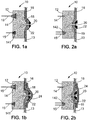
- Figure 1a represents a prefabricated facing element 10 according to a first embodiment of the invention.
- the facing element 10 comprises a first face 12 and a second face 16 opposed to the first face 12, said second face comprises a fixing portion.
- the first face 12 of the facing element 10 comprises a connecting member 14 configured to connect at least a reinforcement member 15 to said facing element 10.
- the connecting member 14 may be an embedded connecting member projecting from the first face 12 as projecting tabs having aligned, vertical passageways therethrough.
- Such reinforcement member reinforces the soil structure.
- Different types of reinforcements can be used: made of metal, for example galvanized steel strips or grids, or of synthetic material, such as stabilizing strips made for example of polyester fibres or polymeric grids.
- the stabilizing reinforcements usually comprise longitudinal portions of elongate shape. Their length is of the order of one metre. They can be several metres in length.
- the longitudinal portions of the reinforcements can be disposed in the soil one by one or assembled together by various means.
- the width and the thickness of such longitudinal portions are of the order of one centimetre and generally do not exceed about ten centimetres.
- the longitudinal portions can be disposed substantially perpendicularly to the facing or inclined relative to the facing.
- the longitudinal portions of the reinforcements are disposed in a substantially horizontal plane.
- the first face may further comprise a connecting member comprising a cavity 141 in which is arranged a liquidproof coating.
- the liquidproof coating for example waterproof coating is arranged in the cavity 141 so as to cover the inside walls of the cavity.
- said cavity forms a hollow space protected from liquids and arranged to receive and connect part of the reinforcement member 15 to the facing element.
- the cavity has a 'T' shape.
- the cavity may comprise a path formed for a reinforcement strip between two emergence points situated on a rear face of the facing.
- the path may comprise two adjacent portions respectively adjacent to the two emergence points and each disposed so as to position said strip in a respective emergence plane substantially perpendicular to the first face of the facing element.
- the two curved portions are provided as respective extensions of the two adjacent portions and are disposed so as to deviate the strip out of the emergence planes, and a connecting portion connecting together the two curved portions.
- the two emergence planes may be identical and the connecting portion comprises at least one loop situated outside the unique emergence plane.
- the two emergence planes may be distinct, separated by a physical separator and substantially parallel to each other in order to form top and bottom emergence planes, and the connecting portion comprises at least one loop situated outside the emergence planes and outside the space between said emergence planes.
- the path may be covered with a protective coating, for example a waterproof coating.
- connecting members are disclosed in application W02011/138105 .
- the second face 16 of the facing element 10 represented on figure 1a is opposed to the first face 12 and is intended to be at least partly covered with a protective membrane 13.
- Said second face 16 has an essentially plane surface intended to be the front or external surface of a reinforced soil structure.
- the facing element comprises a fixing portion intended to fix a protective membrane 13 to the facing element 10 so as to cover the second face 16 of said facing element 10.
- the fixing portion comprises:
- the contact surface 18 projects away from the plane surface of the second face 16 in a direction opposite to the first face 12 of the facing element 10.
- the thickness of the facing element 10 is not reduced by the presence of the contact surface 18.
- the contact surface has a flattened cone shape.
- a flattened cone shape is to be understood as defining a volume corresponding to a flattened cone or a sawn-off cone.
- Said cone may have a pyramidal, circular, square, rectangular or elliptical base.
- a fastening element 20 is anchored to the facing element.
- the fastening element 20 may be anchored to the facing element at the small base of the flattened cone contact surface 18. But it could also be anchored to a side of the flattened cone contact surface 18 or on the surface 16 in the vicinity of the flattened cone contact surface 18.
- the fastening element can be of any known kind, for example an anchor stud comprising a chemical fastening sheath or an anchor stud screwable into a finned tube, embedded in a cement mortar.
- the fastening element 20 is engageable with a tightening element 22 so as to fasten the tightening element against the contact surface.
- the tightening element acts like a hood having essentially the same shape as the contact surface.
- the tightening element 20 can be in plastic, for example thermoplastic, in resin, composite, concrete or fibre concrete, steel, aluminium or stainless steel.
- the tightening element when engaged with the fastening element fastens a protective membrane 13 to the second face 16 of the facing element 10 by pressing, for example sealingly, the protective membrane 13 against the contact surface 18.
- the protective membrane 13 is placed over the second face 16 of the facing element with the fastening element 20 that extends through a hole in the protective membrane 13.
- the tightening element 22 is engaged with the fastening element 20 and is fastened against the contact surface 18 of the facing element 10, thus providing a sealing pressure on the protective membrane 13.
- the protective membrane can for example be a waterproof protective membrane of synthetic resin material, or plastic material in general.
- a protective membrane comprises an elastically flexible and extensible sheet of plastic material, commonly known as "geomembrane", e.g. made of polyvinyl-chloride (PVC), or high density polyethylene (HDPE), polypropylene (PP), or thermal polyolefins (TPO).
- PVC polyvinyl-chloride
- HDPE high density polyethylene
- PP polypropylene
- TPO thermal polyolefins
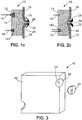
- Figure 2a illustrates a facing element according to an embodiment of the invention similar to the facing element represented on figure 1a , except for the contact surface 19 projecting away from the plane surface of the second face 16 in the direction of the first surface 12.
- the facing element 10 is easy to fabricate.
- the mould used to pour the concrete when fabricating the facing element does not require to be modified.
- the facing element may be obtained by simply placing an element having the desired shape, for example a flattened cone element, a spherical element, or a cylindrical element either at the bottom of the mould prior to poring the concrete or on the facing element before the concrete is solidified. It can also be obtained by placing the tightening element 22 itself in the mould.
- the first face 12 of the facing element illustrated on figure 2a further comprises a cavity 142 in which is arranged a liquidproof coating.
- the cavity 142 has essentially the same features as the cavity 141 of the facing element represented on figure 1a . However the cavity 142 has a 'U' shape.
- Figures 1b and 2b illustrate facing elements similar to the facing elements represented on figures 1a and 2a respectively, wherein a sealing patch 24, for example made of the same material as the protective membrane 13, is sealed to the protective membrane 13 over the tightening element 22.
- the patch is a sheet made of the same material as the protective membrane that covers the tightening element and that is sealed to said protective membrane 13.
- Figures 1b and 2b illustrate facing elements similar to the facing elements represented on figures 1a and 2a respectively, wherein an annular seal 25, for example a plastic annular joint, is provided between the protective membrane 13 and the tightening element 22 so as to ensure the sealing at the fastening point.
- the fixing portion may be positioned on the edge of the second face 16 of the facing element. In other words, the fixing portion may be positioned halfway between the second face and the side of the facing element.
- positioning the fixing means on the edge of the second face allows applying a protective membrane to a reinforced soil structure having an angle of less than 180° between two consecutive columns of facing elements, with the protective membrane always in contact with the external face of the reinforced soil structure.
- the contact surface 19 of the fixing portion has a spherical shape.
- a flattened cone or cylindrical shape could be used.
- the invention also relates to a reinforced soil structure comprising facing elements 10 according to the invention.
- the reinforced structure illustrated on figure 4 comprises:
- the protective membrane 13 may consist of a single protective membrane or of a plurality of protective membranes sealed together.
- the upstream area 34 may comprise a material such as a liquid, for example water, or polluted effluent.
- said upstream area 34 may comprise waste from which toxic liquid materials may escape, or any other elements which are to be confined in front of the front face 9 of the structure 1.
- said upstream area 34 may contain light fluids like gazes.
- the facing 3 is substantially vertical as illustrated in figure 4 , and comprises a front surface substantially the same as the front face 9 of the structure and against which the protective membrane 13 rests, and a back surface 32 situated on the opposite side from the front surface.
- the facing 3 is a concrete wall of any type of concrete known to the art.
- the wall may be constructed in a modular manner with facing elements 10, each of which is being connected to at least a reinforcement member 15 extending through a reinforced zone of the fill 2.
- Each facing element 10 has a first face with at least a connecting member configured to connect to said facing element at least one reinforcement member reinforcing the reinforced soil and a second face opposed to the first face.
- the facing elements are placed along the front face of the structure defined by the second face of the facing element.
- the facing 3 may rest on a specific foundation 5 arranged at the base of the structure, which may ensures the fluid-tightness relative to the underlying soil.
- At least part of the front face of the structure is covered with a protective membrane 13, for example a waterproof membrane. Furthermore, at least part of the substructure 30 is covered with a protective membrane continuously connected to the protective membrane 13 covering at least part of the front face of the structure.
- At least two facing elements of the reinforced structure are facing elements according to the invention, so as to fasten efficiently the protective membrane to the front face of the reinforced soil structure.
- all of the facing elements 10 are facing elements according to the invention.
- joints 36 between the facing elements that are covered with the protective membrane so as to provide the smoothest surface as possible for the protective membrane.
- Figure 5 represents a reinforced soil structure similar to the structure of figure 4 with in addition a protective membrane 17, for example waterproof membrane, on the inner face of the reinforced soil structure.
- the additional inner protective membrane reduces the risk of leak in case the exposed membrane is damaged.
- the inner and front membranes can be sealed together using sealing bridges between different facing elements.
- sealing bridges between different facing elements in case of a leak the fluid penetration between the two membranes could be limited to the sealed area.
- Leaks can be detected by providing detecting means between the two protective membranes.
- Detection means that may be used are thermometers or piezometers.
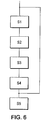
- the reinforced structure illustrated in figure 5 can be obtained by a method as illustrated on figure 6 .
- Said method may comprise:
- facing elements are provided, some of which are according to the invention.
- Said facing elements are positioned so as to have the second face of the facing element along the front face of the structure delimiting a volume to be filled during the positioning step S2.
- At least one reinforcement member is connected to each facing element so as to have the reinforcement member extending through a reinforced zone situated behind said front face.
- Fill material is introduced into said volume over, at least, the reinforced zone in which the reinforcement member extends, and compacted during the filling step S4.
- the optional internal protective membrane is sealed to the inner surface of the structure.
- the sealing of the inner protective membrane is detailed in W02011/138105 .
- the steps 1 to 4 are repeated so as to build the reinforced soil structure.
- a protective membrane is fixed to the front face of the structure using the fixing portions of the facing elements according to the invention.
- a hole is made in the protective membrane and said membrane is placed over the fastening element.
- An annular plastic joint may be added over the protective membrane. The tightening element is engaged with the fastening element and fastened against the contact surface using the fastening element, thus, providing a sealing contact between the protective membrane and the contact surface.
- the fastening of the tightening element also provides a small tension in the protective membrane reducing the risk of having wrinkles appear on the protective membrane.
- a sealing patch may be added over the tightening element to insure a better seal of the protective membrane over the front surface.
- plastic joints may be positioned between each facing elements so as to provide a smoother front face surface for the protective membrane to rest on.
Landscapes
- Engineering & Computer Science (AREA)
- Structural Engineering (AREA)
- Environmental & Geological Engineering (AREA)
- General Life Sciences & Earth Sciences (AREA)
- Mining & Mineral Resources (AREA)
- Paleontology (AREA)
- Civil Engineering (AREA)
- Life Sciences & Earth Sciences (AREA)
- General Engineering & Computer Science (AREA)
- Piles And Underground Anchors (AREA)
- Separation Using Semi-Permeable Membranes (AREA)
- Pit Excavations, Shoring, Fill Or Stabilisation Of Slopes (AREA)
- Retaining Walls (AREA)
- Bridges Or Land Bridges (AREA)
- Road Paving Structures (AREA)
- Working Measures On Existing Buildindgs (AREA)
Priority Applications (15)
| Application Number | Priority Date | Filing Date | Title |
|---|---|---|---|
| ES12305200.3T ES2524691T3 (es) | 2012-02-21 | 2012-02-21 | Un elemento de revestimiento para una estructura de suelo reforzado |
| EP12305200.3A EP2631369B1 (de) | 2012-02-21 | 2012-02-21 | Verkleidungselement für eines verstärkte Bodenstruktur |
| AU2013224174A AU2013224174B2 (en) | 2012-02-21 | 2013-02-19 | A facing element for reinforced soil structure |
| BR112014020473-0A BR112014020473B1 (pt) | 2012-02-21 | 2013-02-19 | elemento de revestimento para estrutura reforçada de solo |
| JP2014558080A JP6193270B2 (ja) | 2012-02-21 | 2013-02-19 | 補強された土壌構造のための壁面要素 |
| MX2014010024A MX343280B (es) | 2012-02-21 | 2013-02-19 | Un elemento de paramento para estructura de suelo reforzado. |
| KR1020147025837A KR20140147087A (ko) | 2012-02-21 | 2013-02-19 | 보강토 구조를 위한 페이싱 요소 |
| CA2864383A CA2864383C (en) | 2012-02-21 | 2013-02-19 | A facing element for reinforced soil structure |
| PE2014001290A PE20142221A1 (es) | 2012-02-21 | 2013-02-19 | Un elemento de paramento para estructura de suelo reforzado |
| PCT/EP2013/053298 WO2013124279A1 (en) | 2012-02-21 | 2013-02-19 | A facing element for reinforced soil structure |
| ARP130100524A AR090109A1 (es) | 2012-02-21 | 2013-02-21 | Un elemento de cobertura para estructura de suelo reforzado, estructura de suelo reforzado y metodo de construccion de una estructura de suelo reforzado |
| US14/379,934 US9175454B2 (en) | 2012-02-21 | 2013-08-19 | Facing element for reinforced soil structure |
| IL234088A IL234088A (en) | 2012-02-21 | 2014-08-12 | Frontal component for reinforced soil structure |
| ZA2014/05929A ZA201405929B (en) | 2012-02-21 | 2014-08-13 | A facing element for reinforced soil structure |
| CL2014002210A CL2014002210A1 (es) | 2012-02-21 | 2014-08-20 | Un elemento de paramento para estructura de suelo reforzado, porque comprende una primera cara que comprende al menos un miembro de conexion configurado para conectar a dicho elemento de paramento al menos un miembro de refuerzo pretendido para reforzar el suelo reforzado; una estructura de suelo reforzado; metodo para construir una estructura de suelo reforzado. |
Applications Claiming Priority (1)
| Application Number | Priority Date | Filing Date | Title |
|---|---|---|---|
| EP12305200.3A EP2631369B1 (de) | 2012-02-21 | 2012-02-21 | Verkleidungselement für eines verstärkte Bodenstruktur |
Publications (2)
| Publication Number | Publication Date |
|---|---|
| EP2631369A1 true EP2631369A1 (de) | 2013-08-28 |
| EP2631369B1 EP2631369B1 (de) | 2014-08-27 |
Family
ID=47740955
Family Applications (1)
| Application Number | Title | Priority Date | Filing Date |
|---|---|---|---|
| EP12305200.3A Active EP2631369B1 (de) | 2012-02-21 | 2012-02-21 | Verkleidungselement für eines verstärkte Bodenstruktur |
Country Status (15)
| Country | Link |
|---|---|
| US (1) | US9175454B2 (de) |
| EP (1) | EP2631369B1 (de) |
| JP (1) | JP6193270B2 (de) |
| KR (1) | KR20140147087A (de) |
| AR (1) | AR090109A1 (de) |
| AU (1) | AU2013224174B2 (de) |
| BR (1) | BR112014020473B1 (de) |
| CA (1) | CA2864383C (de) |
| CL (1) | CL2014002210A1 (de) |
| ES (1) | ES2524691T3 (de) |
| IL (1) | IL234088A (de) |
| MX (1) | MX343280B (de) |
| PE (1) | PE20142221A1 (de) |
| WO (1) | WO2013124279A1 (de) |
| ZA (1) | ZA201405929B (de) |
Families Citing this family (2)
| Publication number | Priority date | Publication date | Assignee | Title |
|---|---|---|---|---|
| WO2020227398A1 (en) * | 2019-05-07 | 2020-11-12 | E.C. Manufacturing, LLC | Landscaping walls, systems and methods |
| US20240169103A1 (en) * | 2022-11-11 | 2024-05-23 | Alejandro Omar Labala | Bio-climatically adapted zero- energy prefabricated modular building and methods thereof with thermal bridge breakages |
Citations (5)
| Publication number | Priority date | Publication date | Assignee | Title |
|---|---|---|---|---|
| US4674921A (en) * | 1984-05-04 | 1987-06-23 | Berger Lawrence E | Seawall |
| US5143480A (en) | 1990-05-29 | 1992-09-01 | Sibelon S.R.L. | Method for protecting dams, with pressureless dehydration by condensation and drainage of the water in the dam body |
| US5580191A (en) * | 1995-02-07 | 1996-12-03 | The Tensar Corporation | Marine wall |
| US20070014638A1 (en) * | 2005-01-19 | 2007-01-18 | Richard Brown | Stabilized earth structure reinforcing elements |
| WO2011138105A2 (en) | 2010-05-07 | 2011-11-10 | Terre Armee Internationale | Continuous fluid tightness for a civil engineering work |
Family Cites Families (11)
| Publication number | Priority date | Publication date | Assignee | Title |
|---|---|---|---|---|
| CA1243497A (en) * | 1986-01-15 | 1988-10-25 | Hugh G. Wilson | Retaining wall structure |
| CA1319261C (fr) * | 1989-08-21 | 1993-06-22 | Valerian Curt | Structures cellulaires pour murs de soutenement |
| GB2276899B (en) * | 1993-03-11 | 1995-12-20 | Cordek Ltd | Improvements in or relating to filling in a hollow in the ground |
| JP3162949B2 (ja) * | 1995-06-05 | 2001-05-08 | 修治 長野 | 廃棄物処分場における遮水シートの敷設構造 |
| GB2356003B (en) * | 1999-11-05 | 2003-10-01 | Rmc | Wall lining method and system |
| JP4287011B2 (ja) * | 2000-02-02 | 2009-07-01 | 東洋建設株式会社 | 遮水シートの敷設構造及び遮水シートの敷設方法 |
| JP3971917B2 (ja) * | 2001-11-26 | 2007-09-05 | 東洋ゴム工業株式会社 | 壁面の表面遮水工に使用される遮水シートの水密性確認方法 |
| JP4230858B2 (ja) * | 2003-08-27 | 2009-02-25 | 三ツ星ベルト株式会社 | 遮水シートの壁面固定構造および同固定方法 |
| JP4368690B2 (ja) * | 2004-01-13 | 2009-11-18 | シバタ工業株式会社 | 海洋構造物の遮水構造 |
| JP5300549B2 (ja) * | 2008-03-24 | 2013-09-25 | 旭化成ジオテック株式会社 | 土構造物の構築方法 |
| JP5388646B2 (ja) * | 2008-03-24 | 2014-01-15 | 旭化成ジオテック株式会社 | 土木用複合体及び土構造物の構築方法 |
-
2012
- 2012-02-21 ES ES12305200.3T patent/ES2524691T3/es active Active
- 2012-02-21 EP EP12305200.3A patent/EP2631369B1/de active Active
-
2013
- 2013-02-19 KR KR1020147025837A patent/KR20140147087A/ko not_active Withdrawn
- 2013-02-19 PE PE2014001290A patent/PE20142221A1/es active IP Right Grant
- 2013-02-19 JP JP2014558080A patent/JP6193270B2/ja active Active
- 2013-02-19 BR BR112014020473-0A patent/BR112014020473B1/pt not_active IP Right Cessation
- 2013-02-19 MX MX2014010024A patent/MX343280B/es active IP Right Grant
- 2013-02-19 WO PCT/EP2013/053298 patent/WO2013124279A1/en not_active Ceased
- 2013-02-19 AU AU2013224174A patent/AU2013224174B2/en not_active Ceased
- 2013-02-19 CA CA2864383A patent/CA2864383C/en active Active
- 2013-02-21 AR ARP130100524A patent/AR090109A1/es active IP Right Grant
- 2013-08-19 US US14/379,934 patent/US9175454B2/en active Active
-
2014
- 2014-08-12 IL IL234088A patent/IL234088A/en active IP Right Grant
- 2014-08-13 ZA ZA2014/05929A patent/ZA201405929B/en unknown
- 2014-08-20 CL CL2014002210A patent/CL2014002210A1/es unknown
Patent Citations (5)
| Publication number | Priority date | Publication date | Assignee | Title |
|---|---|---|---|---|
| US4674921A (en) * | 1984-05-04 | 1987-06-23 | Berger Lawrence E | Seawall |
| US5143480A (en) | 1990-05-29 | 1992-09-01 | Sibelon S.R.L. | Method for protecting dams, with pressureless dehydration by condensation and drainage of the water in the dam body |
| US5580191A (en) * | 1995-02-07 | 1996-12-03 | The Tensar Corporation | Marine wall |
| US20070014638A1 (en) * | 2005-01-19 | 2007-01-18 | Richard Brown | Stabilized earth structure reinforcing elements |
| WO2011138105A2 (en) | 2010-05-07 | 2011-11-10 | Terre Armee Internationale | Continuous fluid tightness for a civil engineering work |
Also Published As
| Publication number | Publication date |
|---|---|
| PE20142221A1 (es) | 2014-12-24 |
| BR112014020473B1 (pt) | 2021-02-09 |
| CA2864383A1 (en) | 2013-08-29 |
| EP2631369B1 (de) | 2014-08-27 |
| IL234088A (en) | 2017-04-30 |
| IL234088A0 (en) | 2014-09-30 |
| JP6193270B2 (ja) | 2017-09-06 |
| ES2524691T3 (es) | 2014-12-11 |
| US20150030394A1 (en) | 2015-01-29 |
| CA2864383C (en) | 2020-09-08 |
| CL2014002210A1 (es) | 2014-12-19 |
| ZA201405929B (en) | 2015-11-25 |
| MX343280B (es) | 2016-10-28 |
| AU2013224174B2 (en) | 2016-11-10 |
| US9175454B2 (en) | 2015-11-03 |
| AU2013224174A1 (en) | 2014-08-28 |
| KR20140147087A (ko) | 2014-12-29 |
| AR090109A1 (es) | 2014-10-22 |
| WO2013124279A1 (en) | 2013-08-29 |
| JP2015508135A (ja) | 2015-03-16 |
| MX2014010024A (es) | 2014-12-05 |
Similar Documents
| Publication | Publication Date | Title |
|---|---|---|
| AU2013263720B2 (en) | Wall Seal System | |
| KR100416570B1 (ko) | 수압구조물에대한불투과성보호막제작방법 | |
| AU2009291241B2 (en) | Method and system for punctual fastening a waterproofing membrane to hydraulic works | |
| EP2567032B1 (de) | Kontinuierliche flüssigkeitsdicke für eine bauarbeit | |
| RS50131B (sr) | Nasip i postupak hidroizolacije | |
| EP2631369B1 (de) | Verkleidungselement für eines verstärkte Bodenstruktur | |
| JP2611940B2 (ja) | 暗渠形組立式水路 |
Legal Events
| Date | Code | Title | Description |
|---|---|---|---|
| PUAI | Public reference made under article 153(3) epc to a published international application that has entered the european phase |
Free format text: ORIGINAL CODE: 0009012 |
|
| AK | Designated contracting states |
Kind code of ref document: A1 Designated state(s): AL AT BE BG CH CY CZ DE DK EE ES FI FR GB GR HR HU IE IS IT LI LT LU LV MC MK MT NL NO PL PT RO RS SE SI SK SM TR |
|
| AX | Request for extension of the european patent |
Extension state: BA ME |
|
| 17P | Request for examination filed |
Effective date: 20140227 |
|
| RBV | Designated contracting states (corrected) |
Designated state(s): AL AT BE BG CH CY CZ DE DK EE ES FI FR GB GR HR HU IE IS IT LI LT LU LV MC MK MT NL NO PL PT RO RS SE SI SK SM TR |
|
| GRAP | Despatch of communication of intention to grant a patent |
Free format text: ORIGINAL CODE: EPIDOSNIGR1 |
|
| INTG | Intention to grant announced |
Effective date: 20140411 |
|
| GRAS | Grant fee paid |
Free format text: ORIGINAL CODE: EPIDOSNIGR3 |
|
| GRAA | (expected) grant |
Free format text: ORIGINAL CODE: 0009210 |
|
| AK | Designated contracting states |
Kind code of ref document: B1 Designated state(s): AL AT BE BG CH CY CZ DE DK EE ES FI FR GB GR HR HU IE IS IT LI LT LU LV MC MK MT NL NO PL PT RO RS SE SI SK SM TR |
|
| REG | Reference to a national code |
Ref country code: GB Ref legal event code: FG4D |
|
| REG | Reference to a national code |
Ref country code: CH Ref legal event code: EP |
|
| REG | Reference to a national code |
Ref country code: AT Ref legal event code: REF Ref document number: 684612 Country of ref document: AT Kind code of ref document: T Effective date: 20140915 |
|
| REG | Reference to a national code |
Ref country code: IE Ref legal event code: FG4D |
|
| REG | Reference to a national code |
Ref country code: DE Ref legal event code: R096 Ref document number: 602012002906 Country of ref document: DE Effective date: 20141009 |
|
| REG | Reference to a national code |
Ref country code: ES Ref legal event code: FG2A Ref document number: 2524691 Country of ref document: ES Kind code of ref document: T3 Effective date: 20141211 |
|
| REG | Reference to a national code |
Ref country code: NL Ref legal event code: T3 |
|
| REG | Reference to a national code |
Ref country code: AT Ref legal event code: MK05 Ref document number: 684612 Country of ref document: AT Kind code of ref document: T Effective date: 20140827 |
|
| REG | Reference to a national code |
Ref country code: NO Ref legal event code: T2 Effective date: 20140827 |
|
| REG | Reference to a national code |
Ref country code: LT Ref legal event code: MG4D |
|
| PG25 | Lapsed in a contracting state [announced via postgrant information from national office to epo] |
Ref country code: BG Free format text: LAPSE BECAUSE OF FAILURE TO SUBMIT A TRANSLATION OF THE DESCRIPTION OR TO PAY THE FEE WITHIN THE PRESCRIBED TIME-LIMIT Effective date: 20141127 Ref country code: LT Free format text: LAPSE BECAUSE OF FAILURE TO SUBMIT A TRANSLATION OF THE DESCRIPTION OR TO PAY THE FEE WITHIN THE PRESCRIBED TIME-LIMIT Effective date: 20140827 Ref country code: PT Free format text: LAPSE BECAUSE OF FAILURE TO SUBMIT A TRANSLATION OF THE DESCRIPTION OR TO PAY THE FEE WITHIN THE PRESCRIBED TIME-LIMIT Effective date: 20141229 Ref country code: SE Free format text: LAPSE BECAUSE OF FAILURE TO SUBMIT A TRANSLATION OF THE DESCRIPTION OR TO PAY THE FEE WITHIN THE PRESCRIBED TIME-LIMIT Effective date: 20140827 Ref country code: FI Free format text: LAPSE BECAUSE OF FAILURE TO SUBMIT A TRANSLATION OF THE DESCRIPTION OR TO PAY THE FEE WITHIN THE PRESCRIBED TIME-LIMIT Effective date: 20140827 Ref country code: GR Free format text: LAPSE BECAUSE OF FAILURE TO SUBMIT A TRANSLATION OF THE DESCRIPTION OR TO PAY THE FEE WITHIN THE PRESCRIBED TIME-LIMIT Effective date: 20141128 |
|
| REG | Reference to a national code |
Ref country code: FR Ref legal event code: CA Effective date: 20150112 |
|
| REG | Reference to a national code |
Ref country code: FR Ref legal event code: PLFP Year of fee payment: 4 |
|
| PG25 | Lapsed in a contracting state [announced via postgrant information from national office to epo] |
Ref country code: HR Free format text: LAPSE BECAUSE OF FAILURE TO SUBMIT A TRANSLATION OF THE DESCRIPTION OR TO PAY THE FEE WITHIN THE PRESCRIBED TIME-LIMIT Effective date: 20140827 Ref country code: CY Free format text: LAPSE BECAUSE OF FAILURE TO SUBMIT A TRANSLATION OF THE DESCRIPTION OR TO PAY THE FEE WITHIN THE PRESCRIBED TIME-LIMIT Effective date: 20140827 Ref country code: IS Free format text: LAPSE BECAUSE OF FAILURE TO SUBMIT A TRANSLATION OF THE DESCRIPTION OR TO PAY THE FEE WITHIN THE PRESCRIBED TIME-LIMIT Effective date: 20141227 Ref country code: AT Free format text: LAPSE BECAUSE OF FAILURE TO SUBMIT A TRANSLATION OF THE DESCRIPTION OR TO PAY THE FEE WITHIN THE PRESCRIBED TIME-LIMIT Effective date: 20140827 Ref country code: LV Free format text: LAPSE BECAUSE OF FAILURE TO SUBMIT A TRANSLATION OF THE DESCRIPTION OR TO PAY THE FEE WITHIN THE PRESCRIBED TIME-LIMIT Effective date: 20140827 Ref country code: RS Free format text: LAPSE BECAUSE OF FAILURE TO SUBMIT A TRANSLATION OF THE DESCRIPTION OR TO PAY THE FEE WITHIN THE PRESCRIBED TIME-LIMIT Effective date: 20140827 |
|
| PG25 | Lapsed in a contracting state [announced via postgrant information from national office to epo] |
Ref country code: EE Free format text: LAPSE BECAUSE OF FAILURE TO SUBMIT A TRANSLATION OF THE DESCRIPTION OR TO PAY THE FEE WITHIN THE PRESCRIBED TIME-LIMIT Effective date: 20140827 Ref country code: SK Free format text: LAPSE BECAUSE OF FAILURE TO SUBMIT A TRANSLATION OF THE DESCRIPTION OR TO PAY THE FEE WITHIN THE PRESCRIBED TIME-LIMIT Effective date: 20140827 Ref country code: DK Free format text: LAPSE BECAUSE OF FAILURE TO SUBMIT A TRANSLATION OF THE DESCRIPTION OR TO PAY THE FEE WITHIN THE PRESCRIBED TIME-LIMIT Effective date: 20140827 Ref country code: CZ Free format text: LAPSE BECAUSE OF FAILURE TO SUBMIT A TRANSLATION OF THE DESCRIPTION OR TO PAY THE FEE WITHIN THE PRESCRIBED TIME-LIMIT Effective date: 20140827 Ref country code: RO Free format text: LAPSE BECAUSE OF FAILURE TO SUBMIT A TRANSLATION OF THE DESCRIPTION OR TO PAY THE FEE WITHIN THE PRESCRIBED TIME-LIMIT Effective date: 20140827 |
|
| REG | Reference to a national code |
Ref country code: DE Ref legal event code: R097 Ref document number: 602012002906 Country of ref document: DE |
|
| PG25 | Lapsed in a contracting state [announced via postgrant information from national office to epo] |
Ref country code: PL Free format text: LAPSE BECAUSE OF FAILURE TO SUBMIT A TRANSLATION OF THE DESCRIPTION OR TO PAY THE FEE WITHIN THE PRESCRIBED TIME-LIMIT Effective date: 20140827 |
|
| PG25 | Lapsed in a contracting state [announced via postgrant information from national office to epo] |
Ref country code: BE Free format text: LAPSE BECAUSE OF NON-PAYMENT OF DUE FEES Effective date: 20150228 |
|
| PLBE | No opposition filed within time limit |
Free format text: ORIGINAL CODE: 0009261 |
|
| STAA | Information on the status of an ep patent application or granted ep patent |
Free format text: STATUS: NO OPPOSITION FILED WITHIN TIME LIMIT |
|
| 26N | No opposition filed |
Effective date: 20150528 |
|
| PG25 | Lapsed in a contracting state [announced via postgrant information from national office to epo] |
Ref country code: LU Free format text: LAPSE BECAUSE OF FAILURE TO SUBMIT A TRANSLATION OF THE DESCRIPTION OR TO PAY THE FEE WITHIN THE PRESCRIBED TIME-LIMIT Effective date: 20150221 |
|
| PG25 | Lapsed in a contracting state [announced via postgrant information from national office to epo] |
Ref country code: MC Free format text: LAPSE BECAUSE OF FAILURE TO SUBMIT A TRANSLATION OF THE DESCRIPTION OR TO PAY THE FEE WITHIN THE PRESCRIBED TIME-LIMIT Effective date: 20140827 |
|
| PG25 | Lapsed in a contracting state [announced via postgrant information from national office to epo] |
Ref country code: SI Free format text: LAPSE BECAUSE OF FAILURE TO SUBMIT A TRANSLATION OF THE DESCRIPTION OR TO PAY THE FEE WITHIN THE PRESCRIBED TIME-LIMIT Effective date: 20140827 |
|
| REG | Reference to a national code |
Ref country code: FR Ref legal event code: PLFP Year of fee payment: 5 |
|
| PG25 | Lapsed in a contracting state [announced via postgrant information from national office to epo] |
Ref country code: BE Free format text: LAPSE BECAUSE OF FAILURE TO SUBMIT A TRANSLATION OF THE DESCRIPTION OR TO PAY THE FEE WITHIN THE PRESCRIBED TIME-LIMIT Effective date: 20140827 |
|
| PG25 | Lapsed in a contracting state [announced via postgrant information from national office to epo] |
Ref country code: MT Free format text: LAPSE BECAUSE OF FAILURE TO SUBMIT A TRANSLATION OF THE DESCRIPTION OR TO PAY THE FEE WITHIN THE PRESCRIBED TIME-LIMIT Effective date: 20140827 |
|
| REG | Reference to a national code |
Ref country code: FR Ref legal event code: PLFP Year of fee payment: 6 |
|
| PG25 | Lapsed in a contracting state [announced via postgrant information from national office to epo] |
Ref country code: HU Free format text: LAPSE BECAUSE OF FAILURE TO SUBMIT A TRANSLATION OF THE DESCRIPTION OR TO PAY THE FEE WITHIN THE PRESCRIBED TIME-LIMIT; INVALID AB INITIO Effective date: 20120221 Ref country code: SM Free format text: LAPSE BECAUSE OF FAILURE TO SUBMIT A TRANSLATION OF THE DESCRIPTION OR TO PAY THE FEE WITHIN THE PRESCRIBED TIME-LIMIT Effective date: 20140827 |
|
| REG | Reference to a national code |
Ref country code: FR Ref legal event code: PLFP Year of fee payment: 7 |
|
| PG25 | Lapsed in a contracting state [announced via postgrant information from national office to epo] |
Ref country code: MK Free format text: LAPSE BECAUSE OF FAILURE TO SUBMIT A TRANSLATION OF THE DESCRIPTION OR TO PAY THE FEE WITHIN THE PRESCRIBED TIME-LIMIT Effective date: 20140827 |
|
| PG25 | Lapsed in a contracting state [announced via postgrant information from national office to epo] |
Ref country code: AL Free format text: LAPSE BECAUSE OF FAILURE TO SUBMIT A TRANSLATION OF THE DESCRIPTION OR TO PAY THE FEE WITHIN THE PRESCRIBED TIME-LIMIT Effective date: 20140827 |
|
| PGFP | Annual fee paid to national office [announced via postgrant information from national office to epo] |
Ref country code: NL Payment date: 20200127 Year of fee payment: 9 Ref country code: IT Payment date: 20200121 Year of fee payment: 9 Ref country code: NO Payment date: 20200127 Year of fee payment: 9 |
|
| PGFP | Annual fee paid to national office [announced via postgrant information from national office to epo] |
Ref country code: CH Payment date: 20200123 Year of fee payment: 9 |
|
| REG | Reference to a national code |
Ref country code: NO Ref legal event code: MMEP |
|
| PG25 | Lapsed in a contracting state [announced via postgrant information from national office to epo] |
Ref country code: CH Free format text: LAPSE BECAUSE OF NON-PAYMENT OF DUE FEES Effective date: 20210228 Ref country code: LI Free format text: LAPSE BECAUSE OF NON-PAYMENT OF DUE FEES Effective date: 20210228 |
|
| PG25 | Lapsed in a contracting state [announced via postgrant information from national office to epo] |
Ref country code: NO Free format text: LAPSE BECAUSE OF NON-PAYMENT OF DUE FEES Effective date: 20210228 |
|
| REG | Reference to a national code |
Ref country code: NL Ref legal event code: MM Effective date: 20210301 |
|
| PG25 | Lapsed in a contracting state [announced via postgrant information from national office to epo] |
Ref country code: NL Free format text: LAPSE BECAUSE OF NON-PAYMENT OF DUE FEES Effective date: 20210301 |
|
| PG25 | Lapsed in a contracting state [announced via postgrant information from national office to epo] |
Ref country code: IT Free format text: LAPSE BECAUSE OF NON-PAYMENT OF DUE FEES Effective date: 20210221 |
|
| P01 | Opt-out of the competence of the unified patent court (upc) registered |
Effective date: 20230526 |
|
| PGFP | Annual fee paid to national office [announced via postgrant information from national office to epo] |
Ref country code: ES Payment date: 20240301 Year of fee payment: 13 Ref country code: IE Payment date: 20240125 Year of fee payment: 13 |
|
| PGFP | Annual fee paid to national office [announced via postgrant information from national office to epo] |
Ref country code: DE Payment date: 20240123 Year of fee payment: 13 Ref country code: GB Payment date: 20240123 Year of fee payment: 13 |
|
| PGFP | Annual fee paid to national office [announced via postgrant information from national office to epo] |
Ref country code: TR Payment date: 20240129 Year of fee payment: 13 Ref country code: FR Payment date: 20240123 Year of fee payment: 13 |
|
| REG | Reference to a national code |
Ref country code: DE Ref legal event code: R119 Ref document number: 602012002906 Country of ref document: DE |
|
| GBPC | Gb: european patent ceased through non-payment of renewal fee |
Effective date: 20250221 |
|
| PG25 | Lapsed in a contracting state [announced via postgrant information from national office to epo] |
Ref country code: DE Free format text: LAPSE BECAUSE OF NON-PAYMENT OF DUE FEES Effective date: 20250902 |
|
| PG25 | Lapsed in a contracting state [announced via postgrant information from national office to epo] |
Ref country code: GB Free format text: LAPSE BECAUSE OF NON-PAYMENT OF DUE FEES Effective date: 20250221 |
|
| PG25 | Lapsed in a contracting state [announced via postgrant information from national office to epo] |
Ref country code: FR Free format text: LAPSE BECAUSE OF NON-PAYMENT OF DUE FEES Effective date: 20250228 |
|
| PG25 | Lapsed in a contracting state [announced via postgrant information from national office to epo] |
Ref country code: IE Free format text: LAPSE BECAUSE OF NON-PAYMENT OF DUE FEES Effective date: 20250221 |
|
| REG | Reference to a national code |
Ref country code: ES Ref legal event code: FD2A Effective date: 20260406 |
|
| PG25 | Lapsed in a contracting state [announced via postgrant information from national office to epo] |
Ref country code: ES Free format text: LAPSE BECAUSE OF NON-PAYMENT OF DUE FEES Effective date: 20250222 |