EP2629961B1 - Additive fabrication apparatus and method of layerwise production of a tangible object - Google Patents
Additive fabrication apparatus and method of layerwise production of a tangible object Download PDFInfo
- Publication number
- EP2629961B1 EP2629961B1 EP11776603.0A EP11776603A EP2629961B1 EP 2629961 B1 EP2629961 B1 EP 2629961B1 EP 11776603 A EP11776603 A EP 11776603A EP 2629961 B1 EP2629961 B1 EP 2629961B1
- Authority
- EP
- European Patent Office
- Prior art keywords
- foil
- liquid
- orifice
- applicator
- stage
- Prior art date
- Legal status (The legal status is an assumption and is not a legal conclusion. Google has not performed a legal analysis and makes no representation as to the accuracy of the status listed.)
- Active
Links
Images


Classifications
-
- B—PERFORMING OPERATIONS; TRANSPORTING
- B29—WORKING OF PLASTICS; WORKING OF SUBSTANCES IN A PLASTIC STATE IN GENERAL
- B29C—SHAPING OR JOINING OF PLASTICS; SHAPING OF MATERIAL IN A PLASTIC STATE, NOT OTHERWISE PROVIDED FOR; AFTER-TREATMENT OF THE SHAPED PRODUCTS, e.g. REPAIRING
- B29C64/00—Additive manufacturing, i.e. manufacturing of three-dimensional [3D] objects by additive deposition, additive agglomeration or additive layering, e.g. by 3D printing, stereolithography or selective laser sintering
- B29C64/10—Processes of additive manufacturing
- B29C64/106—Processes of additive manufacturing using only liquids or viscous materials, e.g. depositing a continuous bead of viscous material
- B29C64/124—Processes of additive manufacturing using only liquids or viscous materials, e.g. depositing a continuous bead of viscous material using layers of liquid which are selectively solidified
-
- B—PERFORMING OPERATIONS; TRANSPORTING
- B29—WORKING OF PLASTICS; WORKING OF SUBSTANCES IN A PLASTIC STATE IN GENERAL
- B29C—SHAPING OR JOINING OF PLASTICS; SHAPING OF MATERIAL IN A PLASTIC STATE, NOT OTHERWISE PROVIDED FOR; AFTER-TREATMENT OF THE SHAPED PRODUCTS, e.g. REPAIRING
- B29C67/00—Shaping techniques not covered by groups B29C39/00 - B29C65/00, B29C70/00 or B29C73/00
-
- B—PERFORMING OPERATIONS; TRANSPORTING
- B29—WORKING OF PLASTICS; WORKING OF SUBSTANCES IN A PLASTIC STATE IN GENERAL
- B29C—SHAPING OR JOINING OF PLASTICS; SHAPING OF MATERIAL IN A PLASTIC STATE, NOT OTHERWISE PROVIDED FOR; AFTER-TREATMENT OF THE SHAPED PRODUCTS, e.g. REPAIRING
- B29C35/00—Heating, cooling or curing, e.g. crosslinking or vulcanising; Apparatus therefor
- B29C35/02—Heating or curing, e.g. crosslinking or vulcanizing during moulding, e.g. in a mould
- B29C35/08—Heating or curing, e.g. crosslinking or vulcanizing during moulding, e.g. in a mould by wave energy or particle radiation
- B29C35/0805—Heating or curing, e.g. crosslinking or vulcanizing during moulding, e.g. in a mould by wave energy or particle radiation using electromagnetic radiation
-
- B—PERFORMING OPERATIONS; TRANSPORTING
- B29—WORKING OF PLASTICS; WORKING OF SUBSTANCES IN A PLASTIC STATE IN GENERAL
- B29C—SHAPING OR JOINING OF PLASTICS; SHAPING OF MATERIAL IN A PLASTIC STATE, NOT OTHERWISE PROVIDED FOR; AFTER-TREATMENT OF THE SHAPED PRODUCTS, e.g. REPAIRING
- B29C64/00—Additive manufacturing, i.e. manufacturing of three-dimensional [3D] objects by additive deposition, additive agglomeration or additive layering, e.g. by 3D printing, stereolithography or selective laser sintering
- B29C64/20—Apparatus for additive manufacturing; Details thereof or accessories therefor
- B29C64/205—Means for applying layers
-
- B—PERFORMING OPERATIONS; TRANSPORTING
- B29—WORKING OF PLASTICS; WORKING OF SUBSTANCES IN A PLASTIC STATE IN GENERAL
- B29C—SHAPING OR JOINING OF PLASTICS; SHAPING OF MATERIAL IN A PLASTIC STATE, NOT OTHERWISE PROVIDED FOR; AFTER-TREATMENT OF THE SHAPED PRODUCTS, e.g. REPAIRING
- B29C64/00—Additive manufacturing, i.e. manufacturing of three-dimensional [3D] objects by additive deposition, additive agglomeration or additive layering, e.g. by 3D printing, stereolithography or selective laser sintering
- B29C64/20—Apparatus for additive manufacturing; Details thereof or accessories therefor
- B29C64/245—Platforms or substrates
-
- B—PERFORMING OPERATIONS; TRANSPORTING
- B33—ADDITIVE MANUFACTURING TECHNOLOGY
- B33Y—ADDITIVE MANUFACTURING, i.e. MANUFACTURING OF THREE-DIMENSIONAL [3-D] OBJECTS BY ADDITIVE DEPOSITION, ADDITIVE AGGLOMERATION OR ADDITIVE LAYERING, e.g. BY 3-D PRINTING, STEREOLITHOGRAPHY OR SELECTIVE LASER SINTERING
- B33Y10/00—Processes of additive manufacturing
-
- B—PERFORMING OPERATIONS; TRANSPORTING
- B33—ADDITIVE MANUFACTURING TECHNOLOGY
- B33Y—ADDITIVE MANUFACTURING, i.e. MANUFACTURING OF THREE-DIMENSIONAL [3-D] OBJECTS BY ADDITIVE DEPOSITION, ADDITIVE AGGLOMERATION OR ADDITIVE LAYERING, e.g. BY 3-D PRINTING, STEREOLITHOGRAPHY OR SELECTIVE LASER SINTERING
- B33Y30/00—Apparatus for additive manufacturing; Details thereof or accessories therefor
Definitions
- the invention relates to an additive fabrication apparatus and method for layerwise production of a tangible object. It is known to press a small volume of liquid between a foil and a tangible object to provide a thin liquid layer than can be solidified.
- the flexible foil is preferably transparent to curing radiation.
- a firstly formed solid layer of the tangible object is adhered to the underside of the carrier plate by selectively solidifying the liquid. Consecutively formed solid layers are each adhered to a previously formed solid layer, respectively.
- a foil guiding stage is moved to peel off the foil from the earlier solidified layers adhered thereon in order to separate the last formed solid layer from the foil.
- Non-solidified parts of the liquid layer remain on the foil and need to be reconditioned when a new solidification starts.
- EP-A-2199067 discloses the respective preambles of claims 1, 8 and 17.
- an additive fabrication apparatus comprising: a carrier plate (150) capable of supporting a tangible object (50); a foil (6) capable of supporting a liquid layer (30); said carrier plate (150) and foil (6) capable of relative movement with respect to each other so as to bring the liquid layer (30) into contact with the carrier plate or the tangible object (50); an energy source (90) arranged for at least partially solidifying at least part of an intersection pattern in the liquid layer arranged on the foil and in contact with the tangible object; and an applicator system (2) for applying the liquid layer (30) on the foil (6) comprising a first applicator, wherein the first applicator is arranged to alternate between providing a supply condition wherein liquid is supplied to the foil via an orifice and providing an uptake condition wherein liquid is taken up from the foil via the orifice.
- a single orifice may be used for both supply and uptake, or a different orifice may be used in the same applicator for the supply condition and the uptake condition.
- the applicator may be moveable and the supply condition or uptake condition may be dependent on the movement of the applicator.
- a method of layerwise production of a tangible object comprising: moving a foil guiding stage having a contact face and comprising on opposite sides of the contact face a pair of upper and lower foil guiding elements, the lower foil guiding element defining a foil height position (H0) distanced from the contact face, to guide a portion of the foil including a liquid layer from the foil height position H(0), along the contact face to contact a tangible object by movement of the foil guiding stage along the tangible object while keeping the portion of the foil contacting the tangible object stationary relative to the object; providing a liquid supply condition by applying the liquid layer on the foil; at least partially solidifying at least part of an intersection pattern in the liquid layer arranged on the foil and in contact with the tangible object by an energy source; and providing a liquid uptake condition wherein liquid is taken up from the foil into an orifice movable with the foil guiding stage; the uptake condition being dependent on a movement direction of the orifice so that liquid is taken up from the foil into the orifice after solidification of at
- FIG. 1 shows a system 1 according to the invention. While the solidifying method can be applied either in a unidirectional way or in a bidirectional way, an advantage of bidirectional use may be that process time can be gained by avoiding to have to return all the process stages back to their start position before a new cycle can be started. Instead, after a pass in one direction, the stage(s) can reverse instantly and start the process in the opposite direction. This requires a certain mirror symmetry in the machine, so certain elements can switch functions when the direction is switched.
- the system 1 comprises a liquid applicator 2 which, in the shown example, is filled with a liquid 3.
- the system 1 further comprises a construction shape in the form of a flexible foil 6. On the foil 6, a liquid layer is formed of limited height to be brought in contact with the tangible object 50.
- the system 1 further comprises a energy source 90 for solidifying a predetermined area 30 of a layer of the liquid 3, said liquid layer 30 adjoining the construction shape 6, so as to obtain a solid layer of the tangible object 50, the solid layer thus having a predetermined shape.
- the energy source 90 is an energy source arranged to project a pattern through the foil 6 when the liquid layer 30 contacts the tangible object 50.
- the energy source 90 is arranged for at least partially curing at least part of an intersection pattern in the liquid layer 30.
- the construction shape 6 flexible foil 6) is preferably substantially transparent to the radiation.
- carrier plate (z-stage) 150 together with the tangible object 50 including solidified layers adhered thereon are moved upwards.
- the method for layerwise production of a tangible object is a cyclic method, wherein the described steps of positioning, solidifying, and separating together are comprised in a single cycle step of the method.
- the flexible foil 6 has a liquid contacting side for being in contact with the liquid 3 to form liquid layer 30.
- At least a contact face 181 in Figure 1 of the guide 180 is in pressing contact with a side of the flexible foil 6 opposite to the liquid contacting side.
- said pressing contact is realized by a sliding or rolling movement of the guide 180 along said opposite side of the flexible foil 6.
- Lower parts in Figure 1 of the guide 180 are in rolling contact with a support platform by means of rollers 190. 191.
- Both the guide 180 and the energy source 90 are movable relative to the platform 7 via these rollers 17 in either or both directions indicated by arrow 73 in Figure 1 .
- the energy source 90 may be movable respective to the guide 180.
- the foil 6 is transparent to radiation from energy source 90.
- the guide 180 and the energy source 90 are synchronously moving in the right-hand direction of arrow 73 in Figure 1 .
- these contacting parts 30 are time-dependently varying.
- the contacting parts 30 may vary depending, in particular, of the position of the guide 180 relative to the tangible object 50.
- Two foil guiding elements (190, 191) arranged on the stage 180 define a contact height defined by a height H where the tangible object 50 contacts the liquid layer 30 and at least one position H0 distanced from the contact height H, for guiding the foil 6 to or from the contact height to contact the tangible object 50 by movement along the tangible object 50 while keeping the foil fixed relative to the tangible object 50 at least during contacting.
- the foil 6 can be arranged for carrying the solidifiable layer material 30 supplied from a dispenser 2 to the tangible object 50 and for carrying the removed uncured material away from the tangible object 50.
- the uncured material outside the intersection pattern sticks to the moving foil 6 because the adhesive force between the uncured material and the foil 6 are larger than the adhesive force between the uncured material and the tangible object 50.
- the energy source 90 comprises a plurality of individually operable LEDs arranged in rows and columns (not shown).
- the motion of the energy source 90 may be controlled by a controller, which also controls the lighting of the LEDs.
- the energy source 90 may be moved rectilinearly in a direction that extends at an angle with the directions of the rows and columns of a LED array to enhance the effective resolution of the system.
- This technique is described in more detail in copending application EP 07150447.6 in the name of Nederlandse, Organisatie Voor Toegepast- Natuurwetenschappelijk Onderzoek (TNO), which is incorporated herein by reference for further information regarding this aspect.
- the energy source 90 may be positioned on the movable foil guiding stage 180, between the protruding foil guiding elements 190, 191 so as to expose the layer of uncured material through the foil 6.
- the energy source may be covered by a transparent plate, e.g. a glass plate to improve the guidance of the foil 6.
- an energy source 90 is typically limited in length, for example, for working areas of about 50 cm, only about 6 cm length can be realised with elements ('pixels', each having a LED+microlens) of 2 x 2 mm2, and still provide a high resolution of about 15 pixels per mm of working-area-width.
- the term 'solidifiable material' includes any material which is solidifiable (i.e., which can by polymerized and/or cross-linked) by, for example, a UV light, a laser, ionizing radiation (including but not limited to an electron beam, gamma rays or x-rays), or a combination of any of the foregoing.
- the term 'solidifiable material' shall also be construed to mean a composite material comprising a mixture of both solidifiable and non-solidifiable materials, such as a resin in which fibers and/or fillers are intermixed.
- Partially curing comprises curing to such a degree that the intersection pattern remains stable while removing the uncured material from the layer outside the intersection pattern.
- the solidifiable material is not fully cured, but only to such an extent that the material is sufficiently stabilized that it is not removed with the uncured material during the step of removing the uncured material outside the intersection pattern.
- Fully curing an intersection pattern needs a certain exposure time. Partially curing the intersection pattern means curing the pattern to a lower degree. When the energy source operates at the same power with which the full curing is done, the exposure may be shorter and the speed of the RM and RP processes increases.
- the transition of a resin cured by UV from liquid to solid passes a so-called gel-point.
- gel-point one first observes the visible formation of a gel or insoluble polymer fraction .
- the gel point is alternately taken as the point at which the system loses fluidity as measured by the failure of an air bubble to rise in it.
- ... The gel corresponds to the formation of an infinite network in which polymer molecules have been crosslinked to each other to form a macroscopic molecule.
- the gel is in fact considered as one molecule.
- the nongel portion of the polymer remains soluble in solvents and is referred to as sol.
- the degree of curing desired in partially curing may be defined by curing the solidifiable material to a degree on or near the gel-point degree of the material, where the intersection pattern remains stable while removing the uncured material from the layer outside the intersection pattern.
- curing to a degree on or near the gel-point degree may be interpreted as a degree within a range of about 80% - 120% of the gel-point degree.
- Curing at least part of the intersection pattern includes fully curing as well, as opposed to the partially curing being described above, of a raster pattern in the layer of solidifiable material 3, said raster pattern being dimensioned to hold uncured material.
- the material may thus be fully cured, but only a raster pattern is cured instead of the complete intersection pattern.
- a laser source may e.g. travel a shorter path, which increases the RP and RM speed.
- a combination of partially curing and curing at least part of an intersection pattern for example, curing a raster of the intersection pattern to a certain degree only, is also possible. This may further speed up the RP and RM process.
- the squeegee is formed as a wedged plate part having a wedge side adjacent the foil.
- this squeegee makes an angle alpha of approximately 10 degrees with the foil 6, that is, the wedge side is angled relative to the plane of foil 6. This approximate angle was found to have the best scraping capability in one direction and the capability to allow resin to pass in the opposite direction, thus retrieving any resin left on the foil rather than pushing it to the edge of the machine.
- the wedged plate part retains the resin on a side away from the wedge side. Accordingly, reservoir 3 is enclosed all around: by the squeegee 1001 and by the upward running part of the foil 6.
- the squeegee 1001 may include extensions having openings for passing shafts of lower roller 190, and seals around the shaft passings. In a bidirectional embodiment, a reservoir 3 is formed on each side of the roller 190. Accordingly, the applicator 2 discloses the wedged plate part 1001 having a wedge side 103, the wedged plate part 1001 enclosing the resin on a side away from the wedge side 103, the wedge side adjacent and being angled relative to the plane of foil.
- a liquid layer 30 providing profiled roller (e.g., a Meyer bar) 190 also on each side of the foil guiding stage.
- the application roller 190 is arranged to apply the resin layer on the side away from the liquid bath 3.
- the wedged plate part 1001 is arranged opposite profiled application roller 190 to form a resin bath 3.
- the thickness of the liquid layer 30 provided by the coater bars is at least equal to the thickness of the next layer, but preferably a bit more.
- a good value for the liquid layer 30 thickness is around 70 - 80 um.
- the rollers that provide the liquid layer 30 are preferably knurled, or profiled, so that the amount of resin that is transported in the recesses of the Meyer bar from the reservoir side of the Meyer bar to the exposure unit side of the Meyer bar is sufficient to provide the desired (in the example: 70 - 80 um) thickness of liquid layer 30.
- the liquid in the recesses only partly remains on the foil behind the Meyer bars, and part stays on the Meyer bar. Therefore the size of the recesses has to be determined experimentally.
- a typical groove width of the Meyer bar is 0.5 mm and a groove height can be also around 0.5 mm.
- the outer ridges of the grooves of the bar are about 50 micron distanced from the foil.
- the resin For the building process to work well, between the exposure and the separation from the foil, the resin should be cured to a certain extent, in order for the newly formed layer to adhere to the previously built layers of the object.
- resins e.g. DSM Somos ® 8120 (an epoxy acrylate), exposed at 365 nm, curing is faster at a higher temperature.
- the mentioned resin is found in an embodiment to work well when used above room temperature, preferably approximately between 30 and 40 °C.
- the foil side facing the liquid layer 30 should easily separate from (fully or partially) cured resin.
- Materials that meet this condition include but are not limited to TPX (bulk), silicone (applied as a coating on a foil of different material) and other materials that allow for easy separation.
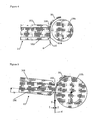
- Figure 2 provides additional disclosure of a bidirectional embodiment wherein the stage is segmented in sub stages supporting lower and upper rollers 19aL, 19aH, energy source 90 and lower and upper rollers 19bL, 19bH respectively.
- advantageously separate sub stages for the exposure unit (180 c) and for the equipment on either side of the exposure unit (180 a and 180 b) are used in contrast to previously disclosed single stages. This has the advantage that the distance between the stage can be optimized for the movement direction, in dependency of the times required for the different subprocesses.
- Lower roller 19aL has the function of providing the liquid layer 30
- upper roller 19aH has the function of lifting the coated foil up to the level H;
- Figure 3 shows a detailed view on an alternative wedged plate configuration. While in the previous embodiment the wedged plate arranged to retain the liquid on one side of the plate; in another embodiment, the wedge plate can be provided with a second wedge plate to form a slotted orifice 21 arranged to apply the liquid layer 30 with ambient environment exposure only when the liquid layer 30 is formed. In this configuration the exposure of the liquid layer 30 to the ambience is further reduced relative to the previous embodiment because the liquid volume 3 inside the orifice 21 is unexposed.
- Plate part 100 is arranged opposite a second wedge shaped plate 101 part to form the orifice 21 for resin supply.
- the second wedge shaped plate part 101 defines a smallest distance to the foil in a range of 50 - 200 micron to apply the resin layer 30 on the side away from the first plate part 100.
- the orifice 21 is shaped as a flat rectangular channel of which the bottom and top walls are formed by wedge shaped plate parts 100, 101.
- the plate part 100 can be slightly distanced from the foil 6, typically, the wedge side 103 defines a smallest distance to the foil in a range of 10 -100 micron. This small gap may result in decreasing foil tension and it may prevent mechanical wear of the applicator foil 6 while still performing a removing function to keep the foil clear from liquid in the area away from the stage 180 and keeping the liquid well conditioned by preventing exposure to the ambient environment so that can be prevented that oxygen diffusion into the liquid layer reaches an unacceptable level.
- Oxygen can inhibit the radical polymerisation process of resin, which may compromise the curing process.
- the resin comprises acrylate components which may evaporate substantially faster than epoxy components, depending on chemical structure. Therefore, longer exposure to the ambient environment may result in evaporation which can change the composition of the resin and increases the viscosity of the resin, which may complicate handling of the resin.
- the supply can be provided on any position between upper and lower foil guiding elements 19h and 191 respectively- preferably near upper guiding element 19h as close to the contact face 181 as possible.
- transport times of the liquid layer to the curing section can be reduced since the slotted resin supplies 21, 22 can be placed very close to the section 181 of the foil 6 that is brought in contact with the object.
- Figure 4 shows an advantageous position of the liquid supply 21, wherein at least one of the plate parts is arranged adjacent an upper foil guiding element.
- the term adjacent is used to indicate that the edges are in near abutment of the foil guiding element 19h.
- the gap between the wedged plate's lower edge 104 and the foil guiding element 19h, extending in a plane parallel to the wedge plates defines a smallest distance to the foil in a range of 10 -200 micron. This distance is small enough to retain the resin on the plate 100 and not damage the foil 6.
- the gap between the wedged plate's upper edge 105 and the foil guiding element 19h, extending in a plane parallel to the wedge plate 101 defines a smallest distance to the foil in a range of 50 - 200 micron.
- the plate thickness may be in the order of 1-3 mm.
- a typical layer thickness is about 100 micron, preferably in the order of 50 - 250 micron.
- This arrangement further reduces the time that the resin layer 30 is exposed to the atmosphere so that evaporation and oxygen diffusion can be reduced and resin quality can be controlled during the whole object building process.
- Figure 5 shows a variation of the embodiment of Figure 4 .
- the liquid gap II-II defining the layer thickness is provided between an outer edge 105 of the wedge side 101 and the foil support 19h which may enhance the layer thickness stability since it is made substantially independent of the foil tension.
- the orifice 21 is has a slight tilt with respect to a normal direction N out of a plane parallel to the foil 6, so that outflowing resin 3 is directed with a slight velocity component v against the foil movement V relative to the orifice 21.
- a realistic foil velocity may be in the order of 50-100 mm/s.
- the angled resin outflow may prevent instabilities in layer 30 forming such as air inclusions or layer width variations in the resin.
- a typical angle ranges between 5 and 20 degrees respective to the normal of the foil and can depend on process parameters such as gap width, foil speed, resin viscosity and resin surface tension.
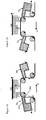
- Figure 6 shows an embodiment having two pressurized orifices 21, 22 substantially symmetrically arranged adjacent both sides of stage 180.
- the resin supply comprises a resin pressurizer P1, P2 to provide a supply or uptake condition depending on a stage movement direction P.
- P1, P2 to provide a supply or uptake condition depending on a stage movement direction P.
- the resin layer 30 is applied by providing a slight overpressure that is sufficient to allow the layer to be formed.
- a typical pressure may be in the order of 0.5 bar, typically 3-6x10 ⁇ 4 Pa with a gradient of about -3x10 ⁇ 7 Pa/m over the plate thickness.
- Figure 7 shows a further embodiment wherein the tilt angle of the orifice is controlled by pivoting the orifice 21, 22 on a pivot point that is close to the outer edge 104 of the wedge side defining the smallest gap height relative to the foil 6 (see Figure 5 ).
- the orifices 21, 22 are tiltably mounted on the stage to have a tilted orientation depending on the supply or uptake condition.
- the orifices on either side of the stage 180 are kept substantially aligned with a slight tilt with respect to a normal direction out of a plane parallel to the foil.
- Figure 7A illustrates this with the stage 180 moving to right in direction Q: effectively the foil moves in upward direction on the right side, while the orifice 22 is oriented with slight tilt with respect to a normal direction out of a plane parallel to the foil so that outflowing resin is directed with a slight velocity component against the foil movement relative to the orifice as illustrated in detail in Figure 5 .
- the left orifice 21 functions as resin uptake by applying a slight under pressure and has a tilt angle which reduces the angle of flow between the liquid layer on the foil and the flow direction in the orifice. It is noted that the angles of left and right orifices in Figure 7A can be favorably mechanically combined but need not be identical.
- Figure 7B shows the reverse direction with the stage 180 moving in a direction P from right to left: here the angles and pressures are reversed dependent on the movement direction respective to Figure 7A .
- the movement direction of the applicator system may be described as, for instance, relative to the tangible object and/or along the foil.
- the orifices 21, 22 may be additionally provided with heating or ultrasound excitation to result in a lower viscosity locally in the slot die, which may improve the liquid supply resin and control over the layer thickness while reducing the over- and underpressures to be provided.
Landscapes
- Engineering & Computer Science (AREA)
- Chemical & Material Sciences (AREA)
- Materials Engineering (AREA)
- Manufacturing & Machinery (AREA)
- Physics & Mathematics (AREA)
- Mechanical Engineering (AREA)
- Optics & Photonics (AREA)
- Health & Medical Sciences (AREA)
- Electromagnetism (AREA)
- Toxicology (AREA)
- Oral & Maxillofacial Surgery (AREA)
- Thermal Sciences (AREA)
Priority Applications (1)
| Application Number | Priority Date | Filing Date | Title |
|---|---|---|---|
| EP11776603.0A EP2629961B1 (en) | 2010-10-22 | 2011-10-21 | Additive fabrication apparatus and method of layerwise production of a tangible object |
Applications Claiming Priority (3)
| Application Number | Priority Date | Filing Date | Title |
|---|---|---|---|
| EP10188605 | 2010-10-22 | ||
| PCT/NL2011/050718 WO2012053895A1 (en) | 2010-10-22 | 2011-10-21 | Additive fabrication apparatus and method of layerwise production of a tangible object |
| EP11776603.0A EP2629961B1 (en) | 2010-10-22 | 2011-10-21 | Additive fabrication apparatus and method of layerwise production of a tangible object |
Publications (2)
| Publication Number | Publication Date |
|---|---|
| EP2629961A1 EP2629961A1 (en) | 2013-08-28 |
| EP2629961B1 true EP2629961B1 (en) | 2015-09-02 |
Family
ID=44898147
Family Applications (1)
| Application Number | Title | Priority Date | Filing Date |
|---|---|---|---|
| EP11776603.0A Active EP2629961B1 (en) | 2010-10-22 | 2011-10-21 | Additive fabrication apparatus and method of layerwise production of a tangible object |
Country Status (5)
| Country | Link |
|---|---|
| US (1) | US20130241113A1 (enExample) |
| EP (1) | EP2629961B1 (enExample) |
| JP (1) | JP6086065B2 (enExample) |
| KR (1) | KR20130141489A (enExample) |
| WO (1) | WO2012053895A1 (enExample) |
Families Citing this family (22)
| Publication number | Priority date | Publication date | Assignee | Title |
|---|---|---|---|---|
| US9636873B2 (en) | 2012-05-03 | 2017-05-02 | B9Creations, LLC | Solid image apparatus with improved part separation from the image plate |
| JP6503375B2 (ja) * | 2014-05-08 | 2019-04-17 | ストラタシス リミテッド | 選択的焼結による3d印刷のための方法及び装置 |
| TWI580519B (zh) * | 2014-06-26 | 2017-05-01 | 三緯國際立體列印科技股份有限公司 | 立體列印裝置 |
| US20180200946A1 (en) * | 2015-07-15 | 2018-07-19 | Stichting Energieonderzoek Centrum Nederland | Method and apparatus for forming thin layers of slurries for additive manufacturing |
| JP6835362B2 (ja) * | 2015-07-15 | 2021-02-24 | アドマテック ヨーロッパ ベー.フェー. | 三次元物体を製造するための付加製造装置 |
| ITUB20154169A1 (it) * | 2015-10-02 | 2017-04-02 | Thelyn S R L | Metodo e apparato di foto-indurimento a substrato auto-lubrificante per la formazione di oggetti tridimensionali. |
| US12064919B2 (en) | 2015-10-15 | 2024-08-20 | Saint-Gobain Ceramics & Plastics, Inc. | Method for forming a three dimensional body from a mixture with a high content of solid particles |
| EP3838442A1 (en) | 2016-04-11 | 2021-06-23 | Stratasys Ltd. | Method and apparatus for additive manufacturing with powder material |
| GB201610267D0 (en) | 2016-06-13 | 2016-07-27 | Digital Metal Ab | Slot die manufacturing apparatus and manufacturing method |
| KR20190126909A (ko) | 2017-03-20 | 2019-11-12 | 스트라타시스 엘티디. | 분말 재료를 이용한 적층 제조용 방법 및 시스템 |
| EP3655465B1 (en) | 2017-07-21 | 2024-09-11 | Saint-Gobain Performance Plastics Corporation | Method of forming a three-dimensional body |
| US11254052B2 (en) | 2017-11-02 | 2022-02-22 | General Electric Company | Vatless additive manufacturing apparatus and method |
| US10682812B2 (en) | 2018-01-10 | 2020-06-16 | General Electric Company | Powder spreader and additive manufacturing apparatus thereof |
| JP7353352B2 (ja) | 2018-07-20 | 2023-09-29 | スリーエム イノベイティブ プロパティズ カンパニー | オブジェクトを層ごとにビルドアップする方法及びこのような方法を実行するための3d印刷装置 |
| US11446860B2 (en) * | 2019-08-16 | 2022-09-20 | General Electric Company | Method and apparatus for separation of cured resin layer from resin support in additive manufacturing |
| US11413819B2 (en) | 2020-09-03 | 2022-08-16 | NEXA3D Inc. | Multi-material membrane for vat polymerization printer |
| KR102255247B1 (ko) * | 2020-10-20 | 2021-05-21 | 손승범 | 바텀 업 타입의 3d 프린터 및 이를 이용한 3d 프린팅 조형물 제조 방법 |
| US11707883B2 (en) | 2020-11-20 | 2023-07-25 | General Electric Company | Foil interaction device for additive manufacturing |
| US11865780B2 (en) * | 2021-02-26 | 2024-01-09 | General Electric Company | Accumalator assembly for additive manufacturing |
| US11826950B2 (en) | 2021-07-09 | 2023-11-28 | General Electric Company | Resin management system for additive manufacturing |
| US20240140031A1 (en) * | 2022-10-26 | 2024-05-02 | Align Technology, Inc. | Additive manufacturing systems with fixed substrates |
| KR102796819B1 (ko) * | 2024-04-12 | 2025-04-18 | 프로토팹 주식회사 | 탑다운 방식의 고점도 3d 프린팅 장치 및 그 3d 프린팅 방법 |
Family Cites Families (6)
| Publication number | Priority date | Publication date | Assignee | Title |
|---|---|---|---|---|
| US5192559A (en) * | 1990-09-27 | 1993-03-09 | 3D Systems, Inc. | Apparatus for building three-dimensional objects with sheets |
| US5922364A (en) * | 1997-03-03 | 1999-07-13 | Young, Jr.; Albert C. | Stereolithography layering control system |
| FR2790418B1 (fr) * | 1999-03-01 | 2001-05-11 | Optoform Sarl Procedes De Prot | Procede de prototypage rapide permettant l'utilisation de materiaux pateux, et dispositif pour sa mise en oeuvre |
| JP2006001259A (ja) * | 2004-06-17 | 2006-01-05 | Isao Ishizaka | 透明フィルムを用いた光造形装置 |
| WO2010074566A1 (en) * | 2008-12-22 | 2010-07-01 | Nederlandse Organisatie Voor Toegepast-Natuurwetenschappelijk Onderzoek Tno | Method and apparatus for layerwise production of a 3d object |
| EP2199067A1 (en) * | 2008-12-22 | 2010-06-23 | Nederlandse Centrale Organisatie Voor Toegepast Natuurwetenschappelijk Onderzoek TNO | Additional light source |
-
2011
- 2011-10-21 JP JP2013534842A patent/JP6086065B2/ja not_active Expired - Fee Related
- 2011-10-21 EP EP11776603.0A patent/EP2629961B1/en active Active
- 2011-10-21 WO PCT/NL2011/050718 patent/WO2012053895A1/en not_active Ceased
- 2011-10-21 KR KR1020137010116A patent/KR20130141489A/ko not_active Withdrawn
- 2011-10-21 US US13/824,118 patent/US20130241113A1/en not_active Abandoned
Also Published As
| Publication number | Publication date |
|---|---|
| EP2629961A1 (en) | 2013-08-28 |
| JP6086065B2 (ja) | 2017-03-01 |
| WO2012053895A1 (en) | 2012-04-26 |
| KR20130141489A (ko) | 2013-12-26 |
| JP2013543801A (ja) | 2013-12-09 |
| US20130241113A1 (en) | 2013-09-19 |
Similar Documents
| Publication | Publication Date | Title |
|---|---|---|
| EP2629961B1 (en) | Additive fabrication apparatus and method of layerwise production of a tangible object | |
| JP2013543801A5 (enExample) | ||
| US8678805B2 (en) | System and method for layerwise production of a tangible object | |
| US8777602B2 (en) | Method and apparatus for layerwise production of a 3D object | |
| EP2379310B1 (en) | Method and apparatus for layerwise production of a 3d object | |
| JP7645266B2 (ja) | リソグラフィに基づく3次元(3d)構造体の付加製造のためのシステム及び方法 | |
| CN112437719B (zh) | 分层构建对象的方法及用于执行此类方法的3d打印装置 | |
| US7467939B2 (en) | Material delivery tension and tracking system for use in solid imaging | |
| US20150131074A1 (en) | Method for the Construction of a Shaped Body | |
| CA2251827A1 (en) | Continuous production of cross-linked resin relief images for printing plates | |
| US12353135B2 (en) | Apparatus and method for generating a relief carrier by irradiation | |
| CN120886469A (zh) | 三维打印设备及三维打印方法 | |
| US12427713B2 (en) | Apparatus and method for generating a 3D structure | |
| CN113290845A (zh) | 一种高粘度及多材料3d打印设备 | |
| EP2272653A1 (en) | Method and apparatus for layerwise production of a 3D object | |
| CN203995001U (zh) | 用于分层生产有形物体的设备 | |
| JP2007290273A (ja) | 光学物品の製造方法及び光学物品及び画像投影スクリ−ン及び画像投影装置 |
Legal Events
| Date | Code | Title | Description |
|---|---|---|---|
| PUAI | Public reference made under article 153(3) epc to a published international application that has entered the european phase |
Free format text: ORIGINAL CODE: 0009012 |
|
| 17P | Request for examination filed |
Effective date: 20130422 |
|
| AK | Designated contracting states |
Kind code of ref document: A1 Designated state(s): AL AT BE BG CH CY CZ DE DK EE ES FI FR GB GR HR HU IE IS IT LI LT LU LV MC MK MT NL NO PL PT RO RS SE SI SK SM TR |
|
| REG | Reference to a national code |
Ref country code: HK Ref legal event code: DE Ref document number: 1182667 Country of ref document: HK |
|
| DAX | Request for extension of the european patent (deleted) | ||
| GRAP | Despatch of communication of intention to grant a patent |
Free format text: ORIGINAL CODE: EPIDOSNIGR1 |
|
| INTG | Intention to grant announced |
Effective date: 20150410 |
|
| GRAS | Grant fee paid |
Free format text: ORIGINAL CODE: EPIDOSNIGR3 |
|
| GRAA | (expected) grant |
Free format text: ORIGINAL CODE: 0009210 |
|
| AK | Designated contracting states |
Kind code of ref document: B1 Designated state(s): AL AT BE BG CH CY CZ DE DK EE ES FI FR GB GR HR HU IE IS IT LI LT LU LV MC MK MT NL NO PL PT RO RS SE SI SK SM TR |
|
| REG | Reference to a national code |
Ref country code: GB Ref legal event code: FG4D |
|
| REG | Reference to a national code |
Ref country code: AT Ref legal event code: REF Ref document number: 746282 Country of ref document: AT Kind code of ref document: T Effective date: 20150915 Ref country code: CH Ref legal event code: EP |
|
| REG | Reference to a national code |
Ref country code: IE Ref legal event code: FG4D |
|
| REG | Reference to a national code |
Ref country code: DE Ref legal event code: R096 Ref document number: 602011019424 Country of ref document: DE |
|
| REG | Reference to a national code |
Ref country code: AT Ref legal event code: MK05 Ref document number: 746282 Country of ref document: AT Kind code of ref document: T Effective date: 20150902 |
|
| REG | Reference to a national code |
Ref country code: FR Ref legal event code: PLFP Year of fee payment: 5 |
|
| PG25 | Lapsed in a contracting state [announced via postgrant information from national office to epo] |
Ref country code: GR Free format text: LAPSE BECAUSE OF FAILURE TO SUBMIT A TRANSLATION OF THE DESCRIPTION OR TO PAY THE FEE WITHIN THE PRESCRIBED TIME-LIMIT Effective date: 20151203 Ref country code: LT Free format text: LAPSE BECAUSE OF FAILURE TO SUBMIT A TRANSLATION OF THE DESCRIPTION OR TO PAY THE FEE WITHIN THE PRESCRIBED TIME-LIMIT Effective date: 20150902 Ref country code: FI Free format text: LAPSE BECAUSE OF FAILURE TO SUBMIT A TRANSLATION OF THE DESCRIPTION OR TO PAY THE FEE WITHIN THE PRESCRIBED TIME-LIMIT Effective date: 20150902 Ref country code: NO Free format text: LAPSE BECAUSE OF FAILURE TO SUBMIT A TRANSLATION OF THE DESCRIPTION OR TO PAY THE FEE WITHIN THE PRESCRIBED TIME-LIMIT Effective date: 20151202 Ref country code: LV Free format text: LAPSE BECAUSE OF FAILURE TO SUBMIT A TRANSLATION OF THE DESCRIPTION OR TO PAY THE FEE WITHIN THE PRESCRIBED TIME-LIMIT Effective date: 20150902 |
|
| REG | Reference to a national code |
Ref country code: NL Ref legal event code: MP Effective date: 20150902 Ref country code: LT Ref legal event code: MG4D |
|
| PG25 | Lapsed in a contracting state [announced via postgrant information from national office to epo] |
Ref country code: SE Free format text: LAPSE BECAUSE OF FAILURE TO SUBMIT A TRANSLATION OF THE DESCRIPTION OR TO PAY THE FEE WITHIN THE PRESCRIBED TIME-LIMIT Effective date: 20150902 Ref country code: RS Free format text: LAPSE BECAUSE OF FAILURE TO SUBMIT A TRANSLATION OF THE DESCRIPTION OR TO PAY THE FEE WITHIN THE PRESCRIBED TIME-LIMIT Effective date: 20150902 Ref country code: AT Free format text: LAPSE BECAUSE OF FAILURE TO SUBMIT A TRANSLATION OF THE DESCRIPTION OR TO PAY THE FEE WITHIN THE PRESCRIBED TIME-LIMIT Effective date: 20150902 Ref country code: ES Free format text: LAPSE BECAUSE OF FAILURE TO SUBMIT A TRANSLATION OF THE DESCRIPTION OR TO PAY THE FEE WITHIN THE PRESCRIBED TIME-LIMIT Effective date: 20150902 Ref country code: HR Free format text: LAPSE BECAUSE OF FAILURE TO SUBMIT A TRANSLATION OF THE DESCRIPTION OR TO PAY THE FEE WITHIN THE PRESCRIBED TIME-LIMIT Effective date: 20150902 Ref country code: PL Free format text: LAPSE BECAUSE OF FAILURE TO SUBMIT A TRANSLATION OF THE DESCRIPTION OR TO PAY THE FEE WITHIN THE PRESCRIBED TIME-LIMIT Effective date: 20150902 |
|
| PG25 | Lapsed in a contracting state [announced via postgrant information from national office to epo] |
Ref country code: IS Free format text: LAPSE BECAUSE OF FAILURE TO SUBMIT A TRANSLATION OF THE DESCRIPTION OR TO PAY THE FEE WITHIN THE PRESCRIBED TIME-LIMIT Effective date: 20160102 Ref country code: NL Free format text: LAPSE BECAUSE OF FAILURE TO SUBMIT A TRANSLATION OF THE DESCRIPTION OR TO PAY THE FEE WITHIN THE PRESCRIBED TIME-LIMIT Effective date: 20150902 Ref country code: EE Free format text: LAPSE BECAUSE OF FAILURE TO SUBMIT A TRANSLATION OF THE DESCRIPTION OR TO PAY THE FEE WITHIN THE PRESCRIBED TIME-LIMIT Effective date: 20150902 Ref country code: SK Free format text: LAPSE BECAUSE OF FAILURE TO SUBMIT A TRANSLATION OF THE DESCRIPTION OR TO PAY THE FEE WITHIN THE PRESCRIBED TIME-LIMIT Effective date: 20150902 Ref country code: CZ Free format text: LAPSE BECAUSE OF FAILURE TO SUBMIT A TRANSLATION OF THE DESCRIPTION OR TO PAY THE FEE WITHIN THE PRESCRIBED TIME-LIMIT Effective date: 20150902 |
|
| PG25 | Lapsed in a contracting state [announced via postgrant information from national office to epo] |
Ref country code: RO Free format text: LAPSE BECAUSE OF FAILURE TO SUBMIT A TRANSLATION OF THE DESCRIPTION OR TO PAY THE FEE WITHIN THE PRESCRIBED TIME-LIMIT Effective date: 20150902 Ref country code: PT Free format text: LAPSE BECAUSE OF FAILURE TO SUBMIT A TRANSLATION OF THE DESCRIPTION OR TO PAY THE FEE WITHIN THE PRESCRIBED TIME-LIMIT Effective date: 20160104 |
|
| REG | Reference to a national code |
Ref country code: DE Ref legal event code: R097 Ref document number: 602011019424 Country of ref document: DE |
|
| PG25 | Lapsed in a contracting state [announced via postgrant information from national office to epo] |
Ref country code: MC Free format text: LAPSE BECAUSE OF FAILURE TO SUBMIT A TRANSLATION OF THE DESCRIPTION OR TO PAY THE FEE WITHIN THE PRESCRIBED TIME-LIMIT Effective date: 20150902 |
|
| PLBE | No opposition filed within time limit |
Free format text: ORIGINAL CODE: 0009261 |
|
| STAA | Information on the status of an ep patent application or granted ep patent |
Free format text: STATUS: NO OPPOSITION FILED WITHIN TIME LIMIT |
|
| REG | Reference to a national code |
Ref country code: IE Ref legal event code: MM4A |
|
| 26N | No opposition filed |
Effective date: 20160603 |
|
| PG25 | Lapsed in a contracting state [announced via postgrant information from national office to epo] |
Ref country code: DK Free format text: LAPSE BECAUSE OF FAILURE TO SUBMIT A TRANSLATION OF THE DESCRIPTION OR TO PAY THE FEE WITHIN THE PRESCRIBED TIME-LIMIT Effective date: 20150902 Ref country code: SI Free format text: LAPSE BECAUSE OF FAILURE TO SUBMIT A TRANSLATION OF THE DESCRIPTION OR TO PAY THE FEE WITHIN THE PRESCRIBED TIME-LIMIT Effective date: 20150902 |
|
| REG | Reference to a national code |
Ref country code: FR Ref legal event code: PLFP Year of fee payment: 6 |
|
| PG25 | Lapsed in a contracting state [announced via postgrant information from national office to epo] |
Ref country code: IE Free format text: LAPSE BECAUSE OF NON-PAYMENT OF DUE FEES Effective date: 20151021 |
|
| REG | Reference to a national code |
Ref country code: DE Ref legal event code: R079 Ref document number: 602011019424 Country of ref document: DE Free format text: PREVIOUS MAIN CLASS: B29C0067000000 Ipc: B29C0064106000 |
|
| PG25 | Lapsed in a contracting state [announced via postgrant information from national office to epo] |
Ref country code: SM Free format text: LAPSE BECAUSE OF FAILURE TO SUBMIT A TRANSLATION OF THE DESCRIPTION OR TO PAY THE FEE WITHIN THE PRESCRIBED TIME-LIMIT Effective date: 20150902 Ref country code: HU Free format text: LAPSE BECAUSE OF FAILURE TO SUBMIT A TRANSLATION OF THE DESCRIPTION OR TO PAY THE FEE WITHIN THE PRESCRIBED TIME-LIMIT; INVALID AB INITIO Effective date: 20111021 Ref country code: BG Free format text: LAPSE BECAUSE OF FAILURE TO SUBMIT A TRANSLATION OF THE DESCRIPTION OR TO PAY THE FEE WITHIN THE PRESCRIBED TIME-LIMIT Effective date: 20150902 |
|
| PG25 | Lapsed in a contracting state [announced via postgrant information from national office to epo] |
Ref country code: CY Free format text: LAPSE BECAUSE OF FAILURE TO SUBMIT A TRANSLATION OF THE DESCRIPTION OR TO PAY THE FEE WITHIN THE PRESCRIBED TIME-LIMIT Effective date: 20150902 |
|
| PG25 | Lapsed in a contracting state [announced via postgrant information from national office to epo] |
Ref country code: MT Free format text: LAPSE BECAUSE OF FAILURE TO SUBMIT A TRANSLATION OF THE DESCRIPTION OR TO PAY THE FEE WITHIN THE PRESCRIBED TIME-LIMIT Effective date: 20150902 |
|
| REG | Reference to a national code |
Ref country code: FR Ref legal event code: PLFP Year of fee payment: 7 |
|
| PG25 | Lapsed in a contracting state [announced via postgrant information from national office to epo] |
Ref country code: LU Free format text: LAPSE BECAUSE OF NON-PAYMENT OF DUE FEES Effective date: 20151021 |
|
| PG25 | Lapsed in a contracting state [announced via postgrant information from national office to epo] |
Ref country code: MK Free format text: LAPSE BECAUSE OF FAILURE TO SUBMIT A TRANSLATION OF THE DESCRIPTION OR TO PAY THE FEE WITHIN THE PRESCRIBED TIME-LIMIT Effective date: 20150902 Ref country code: TR Free format text: LAPSE BECAUSE OF FAILURE TO SUBMIT A TRANSLATION OF THE DESCRIPTION OR TO PAY THE FEE WITHIN THE PRESCRIBED TIME-LIMIT Effective date: 20150902 |
|
| REG | Reference to a national code |
Ref country code: FR Ref legal event code: PLFP Year of fee payment: 8 |
|
| PG25 | Lapsed in a contracting state [announced via postgrant information from national office to epo] |
Ref country code: AL Free format text: LAPSE BECAUSE OF FAILURE TO SUBMIT A TRANSLATION OF THE DESCRIPTION OR TO PAY THE FEE WITHIN THE PRESCRIBED TIME-LIMIT Effective date: 20150902 |
|
| REG | Reference to a national code |
Ref country code: HK Ref legal event code: WD Ref document number: 1182667 Country of ref document: HK |
|
| REG | Reference to a national code |
Ref country code: DE Ref legal event code: R081 Ref document number: 602011019424 Country of ref document: DE Owner name: COVESTRO (NETHERLANDS) B.V., NL Free format text: FORMER OWNER: DSM IP ASSETS B.V., HEERLEN, NL Ref country code: DE Ref legal event code: R081 Ref document number: 602011019424 Country of ref document: DE Owner name: STRATASYS, INC., EDEN PRAIRIE, US Free format text: FORMER OWNER: DSM IP ASSETS B.V., HEERLEN, NL |
|
| REG | Reference to a national code |
Ref country code: GB Ref legal event code: 732E Free format text: REGISTERED BETWEEN 20210923 AND 20210929 |
|
| REG | Reference to a national code |
Ref country code: BE Ref legal event code: PD Owner name: MS HOLDING B.V.; NL Free format text: DETAILS ASSIGNMENT: CHANGE OF OWNER(S), ASSIGNMENT; FORMER OWNER NAME: DSM IP ASSETS B.V. Effective date: 20211015 Ref country code: BE Ref legal event code: HC Owner name: COVESTRO (NETHERLANDS) B.V.; NL Free format text: DETAILS ASSIGNMENT: CHANGE OF OWNER(S), CHANGE OF OWNER(S) NAME; FORMER OWNER NAME: MS HOLDING B.V. Effective date: 20211015 |
|
| REG | Reference to a national code |
Ref country code: DE Ref legal event code: R081 Ref document number: 602011019424 Country of ref document: DE Owner name: COVESTRO (NETHERLANDS) B.V., NL Free format text: FORMER OWNER: COVESTRO (NETHERLANDS) B.V., NIEUWEGEIN, NL Ref country code: DE Ref legal event code: R081 Ref document number: 602011019424 Country of ref document: DE Owner name: STRATASYS, INC., EDEN PRAIRIE, US Free format text: FORMER OWNER: COVESTRO (NETHERLANDS) B.V., NIEUWEGEIN, NL |
|
| PGFP | Annual fee paid to national office [announced via postgrant information from national office to epo] |
Ref country code: BE Payment date: 20220927 Year of fee payment: 12 |
|
| PGFP | Annual fee paid to national office [announced via postgrant information from national office to epo] |
Ref country code: IT Payment date: 20220927 Year of fee payment: 12 |
|
| REG | Reference to a national code |
Ref country code: DE Ref legal event code: R081 Ref document number: 602011019424 Country of ref document: DE Owner name: STRATASYS, INC., EDEN PRAIRIE, US Free format text: FORMER OWNER: COVESTRO (NETHERLANDS) B.V., GELEEN, NL |
|
| REG | Reference to a national code |
Ref country code: BE Ref legal event code: MM Effective date: 20231031 |
|
| PG25 | Lapsed in a contracting state [announced via postgrant information from national office to epo] |
Ref country code: BE Free format text: LAPSE BECAUSE OF NON-PAYMENT OF DUE FEES Effective date: 20231031 |
|
| PG25 | Lapsed in a contracting state [announced via postgrant information from national office to epo] |
Ref country code: IT Free format text: LAPSE BECAUSE OF NON-PAYMENT OF DUE FEES Effective date: 20231021 |
|
| PG25 | Lapsed in a contracting state [announced via postgrant information from national office to epo] |
Ref country code: IT Free format text: LAPSE BECAUSE OF NON-PAYMENT OF DUE FEES Effective date: 20231021 |
|
| PGFP | Annual fee paid to national office [announced via postgrant information from national office to epo] |
Ref country code: DE Payment date: 20240919 Year of fee payment: 14 |
|
| PGFP | Annual fee paid to national office [announced via postgrant information from national office to epo] |
Ref country code: CH Payment date: 20241101 Year of fee payment: 14 |
|
| PGFP | Annual fee paid to national office [announced via postgrant information from national office to epo] |
Ref country code: GB Payment date: 20250923 Year of fee payment: 15 |
|
| PGFP | Annual fee paid to national office [announced via postgrant information from national office to epo] |
Ref country code: FR Payment date: 20250924 Year of fee payment: 15 |
|
| REG | Reference to a national code |
Ref country code: CH Ref legal event code: U11 Free format text: ST27 STATUS EVENT CODE: U-0-0-U10-U11 (AS PROVIDED BY THE NATIONAL OFFICE) Effective date: 20251101 |