EP2629063A2 - Fotoelektrischer Kodierer - Google Patents
Fotoelektrischer Kodierer Download PDFInfo
- Publication number
- EP2629063A2 EP2629063A2 EP13155387.7A EP13155387A EP2629063A2 EP 2629063 A2 EP2629063 A2 EP 2629063A2 EP 13155387 A EP13155387 A EP 13155387A EP 2629063 A2 EP2629063 A2 EP 2629063A2
- Authority
- EP
- European Patent Office
- Prior art keywords
- light beam
- light
- diffraction
- diffraction light
- scale
- Prior art date
- Legal status (The legal status is an assumption and is not a legal conclusion. Google has not performed a legal analysis and makes no representation as to the accuracy of the status listed.)
- Granted
Links
Images


Classifications
-
- G—PHYSICS
- G01—MEASURING; TESTING
- G01D—MEASURING NOT SPECIALLY ADAPTED FOR A SPECIFIC VARIABLE; ARRANGEMENTS FOR MEASURING TWO OR MORE VARIABLES NOT COVERED IN A SINGLE OTHER SUBCLASS; TARIFF METERING APPARATUS; MEASURING OR TESTING NOT OTHERWISE PROVIDED FOR
- G01D5/00—Mechanical means for transferring the output of a sensing member; Means for converting the output of a sensing member to another variable where the form or nature of the sensing member does not constrain the means for converting; Transducers not specially adapted for a specific variable
- G01D5/26—Mechanical means for transferring the output of a sensing member; Means for converting the output of a sensing member to another variable where the form or nature of the sensing member does not constrain the means for converting; Transducers not specially adapted for a specific variable characterised by optical transfer means, i.e. using infrared, visible, or ultraviolet light
- G01D5/32—Mechanical means for transferring the output of a sensing member; Means for converting the output of a sensing member to another variable where the form or nature of the sensing member does not constrain the means for converting; Transducers not specially adapted for a specific variable characterised by optical transfer means, i.e. using infrared, visible, or ultraviolet light with attenuation or whole or partial obturation of beams of light
- G01D5/34—Mechanical means for transferring the output of a sensing member; Means for converting the output of a sensing member to another variable where the form or nature of the sensing member does not constrain the means for converting; Transducers not specially adapted for a specific variable characterised by optical transfer means, i.e. using infrared, visible, or ultraviolet light with attenuation or whole or partial obturation of beams of light the beams of light being detected by photocells
- G01D5/347—Mechanical means for transferring the output of a sensing member; Means for converting the output of a sensing member to another variable where the form or nature of the sensing member does not constrain the means for converting; Transducers not specially adapted for a specific variable characterised by optical transfer means, i.e. using infrared, visible, or ultraviolet light with attenuation or whole or partial obturation of beams of light the beams of light being detected by photocells using displacement encoding scales
- G01D5/34746—Linear encoders
-
- G—PHYSICS
- G01—MEASURING; TESTING
- G01D—MEASURING NOT SPECIALLY ADAPTED FOR A SPECIFIC VARIABLE; ARRANGEMENTS FOR MEASURING TWO OR MORE VARIABLES NOT COVERED IN A SINGLE OTHER SUBCLASS; TARIFF METERING APPARATUS; MEASURING OR TESTING NOT OTHERWISE PROVIDED FOR
- G01D5/00—Mechanical means for transferring the output of a sensing member; Means for converting the output of a sensing member to another variable where the form or nature of the sensing member does not constrain the means for converting; Transducers not specially adapted for a specific variable
- G01D5/26—Mechanical means for transferring the output of a sensing member; Means for converting the output of a sensing member to another variable where the form or nature of the sensing member does not constrain the means for converting; Transducers not specially adapted for a specific variable characterised by optical transfer means, i.e. using infrared, visible, or ultraviolet light
- G01D5/32—Mechanical means for transferring the output of a sensing member; Means for converting the output of a sensing member to another variable where the form or nature of the sensing member does not constrain the means for converting; Transducers not specially adapted for a specific variable characterised by optical transfer means, i.e. using infrared, visible, or ultraviolet light with attenuation or whole or partial obturation of beams of light
- G01D5/34—Mechanical means for transferring the output of a sensing member; Means for converting the output of a sensing member to another variable where the form or nature of the sensing member does not constrain the means for converting; Transducers not specially adapted for a specific variable characterised by optical transfer means, i.e. using infrared, visible, or ultraviolet light with attenuation or whole or partial obturation of beams of light the beams of light being detected by photocells
- G01D5/344—Mechanical means for transferring the output of a sensing member; Means for converting the output of a sensing member to another variable where the form or nature of the sensing member does not constrain the means for converting; Transducers not specially adapted for a specific variable characterised by optical transfer means, i.e. using infrared, visible, or ultraviolet light with attenuation or whole or partial obturation of beams of light the beams of light being detected by photocells using polarisation
- G01D5/345—Polarising encoders
Definitions
- the present invention relates to a photoelectric encoder which is used in a linear encoder etc.
- Photoelectric encoders are used for precise measurements of linear displacements etc.
- a 2-phase detection type photoelectric encoder is widely known which detects light reception quantities of two light beams diffracted by a scale (refer to Fig. 5 of Patent document 1).
- scales are made of an emulsion. The optical characteristics of the scale are varied due to a temperature or humidity variation, as a result of which the measurement accuracy of the photoelectric encoder is lowered.
- One or more exemplary embodiments of the present invention provide a photoelectric encoder in which the degradation in measurement accuracy due to a temperature or humidity variation is suppressed.
- a photoelectric encoder includes an irradiation unit configured to apply first and second irradiation light beams having a first linear polarization direction, a scale configured to produce first and second diffraction light beams having the first linear polarization direction by diffracting the first and second irradiation light beams, respectively, the scale having a glass plate whose front surface has a grating shape, a polarizing unit configured to convert the first diffraction light beam into a third diffraction light beam having a second linear polarization direction which is perpendicular to the first linear polarization direction, to produce first and second composite light beams by combining the second diffraction light beam and the third diffraction light beam, and to convert the first composite light beam into a circularly polarized third composite light beam, and a light receiver configured to receive the second composite light beam and the third composite light beam.
- the invention makes it possible to provide a photoelectric encoder in which the degradation in measurement accuracy due to a temperature or humidity variation is suppressed.
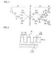
- Fig. 1 is a schematic diagram of a photoelectric encoder according to a first embodiment.
- the photoelectric encoder includes an irradiation unit 10, a scale 20, a polarizing unit 30, and a light receiver 40.
- the photoelectric encoder receives light that is irradiated from the irradiation unit 10 via the scale 20 and the polarizing unit 30.
- the irradiation unit 10, the polarizing unit 30, and the light receiver 40 are moved relative to the scale 20 in the measurement axis direction (i.e., the longitudinal direction of the scale 20), and their movement length is determined on the basis of variations of the light reception quantities of the light receiver 40.
- the irradiation unit 10 outputs s-polarized irradiation light beams L1a and L1b.
- the irradiation unit 10 has a light source 11, a non-polarizing beam splitter 12, and mirrors 13a and 13b.
- the light source 11 applies irradiation light L0 to the non-polarizing beam splitter 12 according to a drive current.
- the wavelength of the irradiation light L0 is set at 655 nm.
- the non-polarizing beam splitter 12 splits the irradiation light L0 into irradiation light beams L1a and L1b and applies them to the respective mirrors 13a and 13b.
- the non-polarizing beam splitter 12 is used to fix the splitting ratio of the s-polarized component (or the p-polarized component).
- the mirrors 13a and 13b reflect the respective irradiation light beams L1a and L1b, and apply the resulting reflection light beams L1a and L1b to the scale 20.
- the mirrors 13a and 13b are disposed symmetrically with respect to the plane that is perpendicular to the measurement axis.
- the scale 20 transmits and diffracts the irradiation light L1a and thereby produces s-polarized diffraction light L2a, and transmits and diffracts the irradiation light L1b and thereby produces s-polarized diffraction light L2b.
- the diffraction light beams L2a and L2b are first-order diffraction light beams of the irradiation light beams L1a and L1b, respectively.
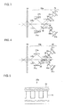
- a diffraction grating 21 is formed on the front surface of the scale 20 by etching a glass substrate directly.
- the diffraction grating 21 formed by etching a glass substrate has an advantage that they are varied less in optical characteristics due to a temperature or humidity variation than a diffraction grating made of an emulsion.
- the thus-formed scale 20 has a disadvantage that the first-order diffraction efficiency of p-polarized light is extremely lower than that of s-polarized light.
- the diffraction grating 21 of the scale 20 is formed by projections and recesses each of which is 0.2 ⁇ m in width and 700 nm in height or depth, and that irradiation light beams L1a and L1b having a wavelength 655 nm are incident onto the scale 20 at an incident angle 54.5°.
- the efficiency of first-order diffraction of p-polarized light by the scale 20 is about 1/10 of that of s-polarized light.
- the diffraction grating 21 of the scale 20 may be formed by projections and recesses each of which is 0.2 ⁇ m in width and 650 to 750 nm in height or depth.
- the angle of incidence of irradiation light beams L1a and L1b on the scale 20 is set at 45° to 65°.
- the efficiency of first-order diffraction of p-polarized light by the scale 20 is about 1/20 to 1/6 of that of s-polarized light.
- the polarizing unit 30 converts the s-polarized diffraction light L2a into p-polarized diffraction light L2c which is perpendicular to the former in polarization direction.
- the polarizing unit 30 produces composite light beams L3a and L3b by combining the diffraction light beams L2b and L2c. Furthermore, the polarizing unit 30 converts the composite light L3a into circularly polarized light L3c.
- the polarizing unit 30 having the above functions can be constructed by mirrors 31a and 31b, a half-wave plate 32, a non-polarizing beam splitter 33, a quarter-wave plate 34, and polarizing plates 35a and 35b.
- the mirrors 31a and 31b reflect the respective diffraction light beams L2a and L2b.
- the mirrors 31a and 31b are disposed symmetrically with respect to the plane that is perpendicular to the measurement axis.
- the half-wave plate 32 converts the s-polarized diffraction light L2a into p-polarized diffraction light L2c by rotating the polarization direction of the former by 90°.
- the non-polarizing beam splitter 33 produces composite light beams L3a and L3b by combining the diffraction light beams L2b and L2c.
- the quarter-wave plate 34 converts the composite light L3a into circularly polarized light L3c by giving a 90° phase difference to the two polarization components of the composite light L3a.
- the polarizing plates 35a and 35b which are disposed in such a manner that their optical axes form 45° with the composite light beams L3c and L3b, respectively, causes the two polarization components to interfere with each other. Resulting interference light beams are received by the light receiver 40.
- the light receiver 40 has an A-phase light receiver 41a and a B-phase light receiver 41b which receive the composite light beams L3c and L3b having a 90° phase difference.
- a direction and a length of a movement of the light receiver 40 relative to the scale 20 are detected on the basis of light reception quantities of the composite light beams L3c and L3b.
- the scale 20 is formed by processing the front surface of a glass substrate into the diffraction grating 21 having the above-described shape. Glass is varied less in optical characteristics due to a temperature or humidity variation than emulsion. Therefore, the photoelectric encoder according to the first embodiment can suppress degradation in measurement accuracy due to a temperature or humidity variation. Furthermore, since the scale 20 used in the first embodiment produces only s-polarized first-order diffraction light beams with high first-order diffraction efficiency (higher than in the case of producing p-polarized first-order diffraction light beams), the light receiver 40 can receive composite light beams L3c and L3b so as to produce large light reception quantities.
- the characteristic of the half-wave plate 32 has a variation. If the polarization direction rotation angle is deviated by such a variation, a phase difference occurs between composite light beams L3c and L3b which are received by the light receiver 40. In view of this, to decrease such a phase difference occurring between the composite light beams L3c and L3b, a polarizing unit 30a used in the second embodiment is constructed so as to be able to decrease the optical path difference between diffraction light beams L2c and L2b.
- the second embodiment is different from the first embodiment only in this feature.
- the polarizing unit 30a used in the second embodiment is constructed so that the angles of the respective mirrors 31a and 31b with respect to the measurement axis are adjustable. The angles of the respective mirrors 31a and 31b with respect to the scale 20 are adjusted so that the optical path difference between the diffraction light beams L2c and L2b is decreased. As described above, in the second embodiment, the polarizing unit 30a is constructed so as to be able to decrease the optical path difference between diffraction light beams L2c and L2b. If the optical path difference between diffraction light beams L2c and L2b is large, the variation of the coherency (signal efficiency) increases in accordance with the wavelength variation of the irradiation light.
- the photoelectric encoder according to the second embodiment since the optical path difference between diffraction light beams L2c and L2b is small, the signal can be stabilized. Further, this variation increases at an accelerated rate as the optical path difference becomes large. However, in the photoelectric encoder according to the second embodiment, since the optical path difference between diffraction light beams L2c and L2b is small, the influence of the dynamic variation (temperature variation, posture variation) of the optical path difference can be made small.
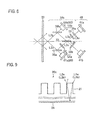
- a photoelectric encoder according to a third embodiment will be described with reference to Fig. 4 .
- a polarizing unit 30b used in the third embodiment is constructed so as to be able to decrease the optical path difference between diffraction light beams L2c and L2b.
- the polarizing unit 30b is constructed so that the angle and the position of the non-polarizing beam splitter 33 with respect to the scale 20 are adjustable. The angle and the position of the non-polarizing beam splitter 33 with respect to the scale 20 are adjusted so that the optical path difference between diffraction light beams L2c and L2b is decreased.
- the fourth embodiment is different from the first to third embodiments only in a scale 20a.
- the scale 20a has a protective layer 22 which covers the front surface of a glass plate 21 and transmits light.
- the protective layer 22 prevents the glass plate 21 from being scratched or stained.
- the protective layer 22 is made of glass or plastic, for example.
- the fifth embodiment is different from the first to fourth embodiments only in a scale 20b.
- the scale 20b has a reflection suppressing layer 23 which is formed on the back surface of a glass plate 21 and suppresses reflection of light. Since the reflection suppressing layer 23 increases the efficiency of first-order diffraction, the intensities of diffraction light beams L2a and L2b can be made higher than in the first embodiment.
- the reflection suppressing layer 23 is an AR coating, for example.
- the photoelectric encoder according to the sixth embodiment includes a light shield 50 in addition to the components of the photoelectric encoder according to the first embodiment.
- the light shield 50 is disposed between the scale 20 and the polarizing unit 30 and interrupts 0th-order diffraction components of respective irradiation light beams L1a and L1b.
- the measurement accuracy can be made higher than in the first embodiment.
- the photoelectric encoder according to the seventh embodiment includes a light receiver 60 in addition to the components of the photoelectric encoder according to the first embodiment.
- the light receiver 60 receives diffraction light beams L2a and L2b and measures light reception quantities S1a and S1b, respectively.
- a polarizing unit 30c has non-polarizing beam splitters 36a and 36b in place of the mirrors 31a and 31b.
- the light receiver 60 has output monitoring light receivers 61a and 61b.
- the non-polarizing beam splitter 36a applies part of the diffraction light L2a to the output monitoring light receiver 61a, and applies the other part of the diffraction light L2a to the non-polarizing beam splitter 33.
- the non-polarizing beam splitter 36b applies part of the diffraction light L2b to the output monitoring light receiver 61b, and applies the other part of the diffraction light L2b to the non-polarizing beam splitter 33.
- the output monitoring light receiver 61a receives the diffraction light L2a and measures a light reception quantity S1a
- the output monitoring light receiver 61b receives the diffraction light L2b and measures a light reception quantity S1b.
- the drive current of the light source 11 is controlled on the basis of the light reception quantities S1a and S1b, whereby the light quantity of irradiation light L0 (L1a and L1b) is controlled so as to be kept constant.
- the eighth embodiment is different from the first to seventh embodiments only in a scale 20c. Whereas scales 20, 20a, and 20b used in the above embodiments transmit light, the scale 20c used in the eighth embodiment reflects light.
- the scale 20c has a reflection layer 24 which is formed on the back surface of a glass substrate 21 and reflects light. Irradiation light beams L1a and L1b incident onto the front surface of the glass substrate 21 are diffracted by the glass substrate 21, reflected by the reflection layer 24, and become diffraction light beams L2a and L2b.
- the reflection layer 24 is made of a metal, for example.
- a reflection photoelectric encoder can be constructed using the scale 20c, in contrast to the fact that transmission photoelectric encoders are constructed according to the first to seventh embodiments.
- a photoelectric encoder according to a ninth embodiment will be described with reference to Fig. 10 .
- a polarizing unit 30d used in the ninth embodiment is constructed so as to be able to decrease the optical path difference between diffraction light beams L2c and L2b.
- the polarizing unit 30d has an optical path length correction member 36 in addition to the components of the polarizing unit 30 according to the first embodiment.
- the optical path length correction member 36 and the half-wave plate 32 are disposed symmetrically with respect to the plane that is perpendicular to the measurement axis.
- the optical path length correction member 36 corrects the optical path length of the diffraction light beam L2b so as to decrease the optical path difference between diffraction light beams L2c and L2b.
- the optical path length correction member 36 is made of a transparent glass plate whose thickness is equal to that of the half-wave plate 32 (the thickness of 0.4mm, for example).
- the optical path length correction member 36 is not limited to this, but, its thickness may be different from that of the half-wave plate 32.
- the optical path length correction member 36 may be a half-wave plate 32 instead of the glass plate. In this case, the direction of an optical axis of the optical path length correction member 36 has to be rotated by 90° with respect to the half-wave plate 32.
- the invention is not limited to them and various modifications, additions, etc. are possible without departing from the spirit and scope of the invention.
- two p-polarized irradiation light beams may be applied to the scale 20. In this case, satisfactory results are obtained as long as the efficiency of first-order diffraction of s-polarized light by the scale 20 is smaller than that of p-polarized light.
- the invention may be combination of the third embodiment and the ninth embodiment.
- such a combination can be decrease the optical path difference between diffraction light beams L2c and L2b based on the amendment of the optical path length of the diffraction light beams L2b by the optical path length correction member 36 and the adjustment of the angle and the position of the non-polarizing beam splitter 33.
Landscapes
- Physics & Mathematics (AREA)
- General Physics & Mathematics (AREA)
- Optical Transform (AREA)
Applications Claiming Priority (1)
| Application Number | Priority Date | Filing Date | Title |
|---|---|---|---|
| JP2012033290A JP6093965B2 (ja) | 2012-02-17 | 2012-02-17 | 光電式エンコーダ |
Publications (3)
| Publication Number | Publication Date |
|---|---|
| EP2629063A2 true EP2629063A2 (de) | 2013-08-21 |
| EP2629063A3 EP2629063A3 (de) | 2014-04-23 |
| EP2629063B1 EP2629063B1 (de) | 2018-10-24 |
Family
ID=47713967
Family Applications (1)
| Application Number | Title | Priority Date | Filing Date |
|---|---|---|---|
| EP13155387.7A Active EP2629063B1 (de) | 2012-02-17 | 2013-02-15 | Fotoelektrischer Kodierer |
Country Status (3)
| Country | Link |
|---|---|
| US (1) | US9329059B2 (de) |
| EP (1) | EP2629063B1 (de) |
| JP (1) | JP6093965B2 (de) |
Families Citing this family (5)
| Publication number | Priority date | Publication date | Assignee | Title |
|---|---|---|---|---|
| WO2014061079A1 (ja) * | 2012-10-15 | 2014-04-24 | 富士通株式会社 | 方向検知装置、方向検知方法、方向検知制御プログラム |
| JP6427399B2 (ja) * | 2014-04-14 | 2018-11-21 | Dmg森精機株式会社 | 変位検出装置 |
| US10126560B2 (en) * | 2016-02-18 | 2018-11-13 | National Engineering Research Center for Optical Instrumentation | Spectrum-generation system based on multiple-diffraction optical phasometry |
| JP7102058B2 (ja) * | 2017-05-22 | 2022-07-19 | 株式会社ミツトヨ | 光電式エンコーダ |
| DE102017213330A1 (de) * | 2017-08-02 | 2019-02-07 | Dr. Johannes Heidenhain Gmbh | Abtastplatte für eine optische Positionsmesseinrichtung |
Citations (1)
| Publication number | Priority date | Publication date | Assignee | Title |
|---|---|---|---|---|
| JP2003247867A (ja) | 2002-02-25 | 2003-09-05 | Mitsutoyo Corp | 格子干渉型変位測定装置 |
Family Cites Families (8)
| Publication number | Priority date | Publication date | Assignee | Title |
|---|---|---|---|---|
| JP3407477B2 (ja) * | 1995-06-08 | 2003-05-19 | 松下電器産業株式会社 | 位相格子とその作製方法並びに光学式エンコーダ |
| JP4154038B2 (ja) * | 1998-08-20 | 2008-09-24 | ソニーマニュファクチュアリングシステムズ株式会社 | 光学式変位測定装置 |
| JP4023923B2 (ja) | 1998-07-02 | 2007-12-19 | ソニーマニュファクチュアリングシステムズ株式会社 | 光学式変位測定装置 |
| KR100531458B1 (ko) | 1998-08-20 | 2005-11-25 | 소니 매뉴펙츄어링 시스템즈 코포레이션 | 광학식 변위측정장치 |
| KR100388232B1 (ko) * | 2000-08-22 | 2003-06-19 | (주)해빛정보 | 유리기판상의 격자패턴 형성방법 |
| EP2818927B1 (de) * | 2007-07-18 | 2016-04-27 | Nikon Corporation | Messverfahren, Trägervorrichtung und Belichtungsvorrichtung |
| JP2011053495A (ja) * | 2009-09-02 | 2011-03-17 | Sony Corp | 光学素子、およびその製造方法 |
| JP5724213B2 (ja) * | 2010-05-13 | 2015-05-27 | セイコーエプソン株式会社 | 検出装置 |
-
2012
- 2012-02-17 JP JP2012033290A patent/JP6093965B2/ja active Active
-
2013
- 2013-02-14 US US13/767,101 patent/US9329059B2/en active Active
- 2013-02-15 EP EP13155387.7A patent/EP2629063B1/de active Active
Patent Citations (1)
| Publication number | Priority date | Publication date | Assignee | Title |
|---|---|---|---|---|
| JP2003247867A (ja) | 2002-02-25 | 2003-09-05 | Mitsutoyo Corp | 格子干渉型変位測定装置 |
Also Published As
| Publication number | Publication date |
|---|---|
| US9329059B2 (en) | 2016-05-03 |
| EP2629063B1 (de) | 2018-10-24 |
| US20130214137A1 (en) | 2013-08-22 |
| JP2013170852A (ja) | 2013-09-02 |
| EP2629063A3 (de) | 2014-04-23 |
| JP6093965B2 (ja) | 2017-03-15 |
Similar Documents
| Publication | Publication Date | Title |
|---|---|---|
| US9097511B2 (en) | Displacement detecting device with a polarization change to a twice-diffracted beam | |
| US8687202B2 (en) | Displacement detecting device | |
| EP2629063B1 (de) | Fotoelektrischer Kodierer | |
| US9175987B2 (en) | Displacement detecting device | |
| US9080857B2 (en) | Device for interferential distance measurement | |
| US11199400B2 (en) | Optical angle sensor | |
| CN104729402A (zh) | 基于平面镜的高光学细分光栅干涉仪 | |
| CN104729411B (zh) | 基于高密度光栅的高分辨率光栅干涉仪 | |
| US6956654B2 (en) | Displacement measuring device with interference grating | |
| KR101822566B1 (ko) | 위치 검출 장치 | |
| CN104634280A (zh) | 通用水平转台绝对角度和旋转角度的测量方法 | |
| CN112097652A (zh) | 光栅位移测量装置 | |
| CN116804588A (zh) | 一种光栅衍射效率测量装置 | |
| JP5235554B2 (ja) | 光学式変位測定装置 | |
| CN105180800B (zh) | 自准直光栅干涉仪的高光学细分结构 | |
| US9863810B2 (en) | Optical device for improved wavelength resolution and wavelength accuracy | |
| KR100997948B1 (ko) | 변위와 변각을 동시에 측정하는 장치 | |
| JP5923132B2 (ja) | レーザ加工装置用の偏光状態変換素子 | |
| JPH046884B2 (de) | ||
| WO2024146600A1 (zh) | 干涉解调装置和干涉测量系统 | |
| US7933023B2 (en) | Displacement detection apparatus, displacement measurement apparatus and fixed point detection apparatus | |
| JP2003035570A (ja) | 回折干渉式リニアスケール | |
| JP2557967B2 (ja) | 格子干渉型変位計 | |
| TWI414756B (zh) | Dual grating signal measurement system | |
| JP2020076593A (ja) | 変位検出装置 |
Legal Events
| Date | Code | Title | Description |
|---|---|---|---|
| PUAI | Public reference made under article 153(3) epc to a published international application that has entered the european phase |
Free format text: ORIGINAL CODE: 0009012 |
|
| AK | Designated contracting states |
Kind code of ref document: A2 Designated state(s): AL AT BE BG CH CY CZ DE DK EE ES FI FR GB GR HR HU IE IS IT LI LT LU LV MC MK MT NL NO PL PT RO RS SE SI SK SM TR |
|
| AX | Request for extension of the european patent |
Extension state: BA ME |
|
| PUAL | Search report despatched |
Free format text: ORIGINAL CODE: 0009013 |
|
| AK | Designated contracting states |
Kind code of ref document: A3 Designated state(s): AL AT BE BG CH CY CZ DE DK EE ES FI FR GB GR HR HU IE IS IT LI LT LU LV MC MK MT NL NO PL PT RO RS SE SI SK SM TR |
|
| AX | Request for extension of the european patent |
Extension state: BA ME |
|
| RIC1 | Information provided on ipc code assigned before grant |
Ipc: G01D 5/26 20060101AFI20140319BHEP |
|
| 17P | Request for examination filed |
Effective date: 20140902 |
|
| RBV | Designated contracting states (corrected) |
Designated state(s): AL AT BE BG CH CY CZ DE DK EE ES FI FR GB GR HR HU IE IS IT LI LT LU LV MC MK MT NL NO PL PT RO RS SE SI SK SM TR |
|
| 17Q | First examination report despatched |
Effective date: 20160629 |
|
| REG | Reference to a national code |
Ref country code: DE Ref legal event code: R079 Ref document number: 602013045438 Country of ref document: DE Free format text: PREVIOUS MAIN CLASS: G01D0005260000 Ipc: G01D0005340000 |
|
| STAA | Information on the status of an ep patent application or granted ep patent |
Free format text: STATUS: EXAMINATION IS IN PROGRESS |
|
| RIC1 | Information provided on ipc code assigned before grant |
Ipc: G01D 5/347 20060101ALI20170824BHEP Ipc: G01D 5/34 20060101AFI20170824BHEP |
|
| GRAP | Despatch of communication of intention to grant a patent |
Free format text: ORIGINAL CODE: EPIDOSNIGR1 |
|
| STAA | Information on the status of an ep patent application or granted ep patent |
Free format text: STATUS: GRANT OF PATENT IS INTENDED |
|
| INTG | Intention to grant announced |
Effective date: 20180518 |
|
| GRAS | Grant fee paid |
Free format text: ORIGINAL CODE: EPIDOSNIGR3 |
|
| GRAA | (expected) grant |
Free format text: ORIGINAL CODE: 0009210 |
|
| STAA | Information on the status of an ep patent application or granted ep patent |
Free format text: STATUS: THE PATENT HAS BEEN GRANTED |
|
| AK | Designated contracting states |
Kind code of ref document: B1 Designated state(s): AL AT BE BG CH CY CZ DE DK EE ES FI FR GB GR HR HU IE IS IT LI LT LU LV MC MK MT NL NO PL PT RO RS SE SI SK SM TR |
|
| REG | Reference to a national code |
Ref country code: CH Ref legal event code: EP |
|
| REG | Reference to a national code |
Ref country code: IE Ref legal event code: FG4D |
|
| REG | Reference to a national code |
Ref country code: AT Ref legal event code: REF Ref document number: 1057237 Country of ref document: AT Kind code of ref document: T Effective date: 20181115 |
|
| REG | Reference to a national code |
Ref country code: DE Ref legal event code: R096 Ref document number: 602013045438 Country of ref document: DE |
|
| REG | Reference to a national code |
Ref country code: NL Ref legal event code: MP Effective date: 20181024 |
|
| REG | Reference to a national code |
Ref country code: LT Ref legal event code: MG4D |
|
| REG | Reference to a national code |
Ref country code: AT Ref legal event code: MK05 Ref document number: 1057237 Country of ref document: AT Kind code of ref document: T Effective date: 20181024 |
|
| PG25 | Lapsed in a contracting state [announced via postgrant information from national office to epo] |
Ref country code: NL Free format text: LAPSE BECAUSE OF FAILURE TO SUBMIT A TRANSLATION OF THE DESCRIPTION OR TO PAY THE FEE WITHIN THE PRESCRIBED TIME-LIMIT Effective date: 20181024 |
|
| PG25 | Lapsed in a contracting state [announced via postgrant information from national office to epo] |
Ref country code: AT Free format text: LAPSE BECAUSE OF FAILURE TO SUBMIT A TRANSLATION OF THE DESCRIPTION OR TO PAY THE FEE WITHIN THE PRESCRIBED TIME-LIMIT Effective date: 20181024 Ref country code: HR Free format text: LAPSE BECAUSE OF FAILURE TO SUBMIT A TRANSLATION OF THE DESCRIPTION OR TO PAY THE FEE WITHIN THE PRESCRIBED TIME-LIMIT Effective date: 20181024 Ref country code: LT Free format text: LAPSE BECAUSE OF FAILURE TO SUBMIT A TRANSLATION OF THE DESCRIPTION OR TO PAY THE FEE WITHIN THE PRESCRIBED TIME-LIMIT Effective date: 20181024 Ref country code: NO Free format text: LAPSE BECAUSE OF FAILURE TO SUBMIT A TRANSLATION OF THE DESCRIPTION OR TO PAY THE FEE WITHIN THE PRESCRIBED TIME-LIMIT Effective date: 20190124 Ref country code: LV Free format text: LAPSE BECAUSE OF FAILURE TO SUBMIT A TRANSLATION OF THE DESCRIPTION OR TO PAY THE FEE WITHIN THE PRESCRIBED TIME-LIMIT Effective date: 20181024 Ref country code: FI Free format text: LAPSE BECAUSE OF FAILURE TO SUBMIT A TRANSLATION OF THE DESCRIPTION OR TO PAY THE FEE WITHIN THE PRESCRIBED TIME-LIMIT Effective date: 20181024 Ref country code: IS Free format text: LAPSE BECAUSE OF FAILURE TO SUBMIT A TRANSLATION OF THE DESCRIPTION OR TO PAY THE FEE WITHIN THE PRESCRIBED TIME-LIMIT Effective date: 20190224 Ref country code: ES Free format text: LAPSE BECAUSE OF FAILURE TO SUBMIT A TRANSLATION OF THE DESCRIPTION OR TO PAY THE FEE WITHIN THE PRESCRIBED TIME-LIMIT Effective date: 20181024 Ref country code: PL Free format text: LAPSE BECAUSE OF FAILURE TO SUBMIT A TRANSLATION OF THE DESCRIPTION OR TO PAY THE FEE WITHIN THE PRESCRIBED TIME-LIMIT Effective date: 20181024 Ref country code: BG Free format text: LAPSE BECAUSE OF FAILURE TO SUBMIT A TRANSLATION OF THE DESCRIPTION OR TO PAY THE FEE WITHIN THE PRESCRIBED TIME-LIMIT Effective date: 20190124 |
|
| PG25 | Lapsed in a contracting state [announced via postgrant information from national office to epo] |
Ref country code: GR Free format text: LAPSE BECAUSE OF FAILURE TO SUBMIT A TRANSLATION OF THE DESCRIPTION OR TO PAY THE FEE WITHIN THE PRESCRIBED TIME-LIMIT Effective date: 20190125 Ref country code: AL Free format text: LAPSE BECAUSE OF FAILURE TO SUBMIT A TRANSLATION OF THE DESCRIPTION OR TO PAY THE FEE WITHIN THE PRESCRIBED TIME-LIMIT Effective date: 20181024 Ref country code: PT Free format text: LAPSE BECAUSE OF FAILURE TO SUBMIT A TRANSLATION OF THE DESCRIPTION OR TO PAY THE FEE WITHIN THE PRESCRIBED TIME-LIMIT Effective date: 20190224 Ref country code: SE Free format text: LAPSE BECAUSE OF FAILURE TO SUBMIT A TRANSLATION OF THE DESCRIPTION OR TO PAY THE FEE WITHIN THE PRESCRIBED TIME-LIMIT Effective date: 20181024 Ref country code: RS Free format text: LAPSE BECAUSE OF FAILURE TO SUBMIT A TRANSLATION OF THE DESCRIPTION OR TO PAY THE FEE WITHIN THE PRESCRIBED TIME-LIMIT Effective date: 20181024 |
|
| REG | Reference to a national code |
Ref country code: DE Ref legal event code: R097 Ref document number: 602013045438 Country of ref document: DE |
|
| PG25 | Lapsed in a contracting state [announced via postgrant information from national office to epo] |
Ref country code: DK Free format text: LAPSE BECAUSE OF FAILURE TO SUBMIT A TRANSLATION OF THE DESCRIPTION OR TO PAY THE FEE WITHIN THE PRESCRIBED TIME-LIMIT Effective date: 20181024 Ref country code: CZ Free format text: LAPSE BECAUSE OF FAILURE TO SUBMIT A TRANSLATION OF THE DESCRIPTION OR TO PAY THE FEE WITHIN THE PRESCRIBED TIME-LIMIT Effective date: 20181024 Ref country code: IT Free format text: LAPSE BECAUSE OF FAILURE TO SUBMIT A TRANSLATION OF THE DESCRIPTION OR TO PAY THE FEE WITHIN THE PRESCRIBED TIME-LIMIT Effective date: 20181024 |
|
| PG25 | Lapsed in a contracting state [announced via postgrant information from national office to epo] |
Ref country code: RO Free format text: LAPSE BECAUSE OF FAILURE TO SUBMIT A TRANSLATION OF THE DESCRIPTION OR TO PAY THE FEE WITHIN THE PRESCRIBED TIME-LIMIT Effective date: 20181024 Ref country code: SM Free format text: LAPSE BECAUSE OF FAILURE TO SUBMIT A TRANSLATION OF THE DESCRIPTION OR TO PAY THE FEE WITHIN THE PRESCRIBED TIME-LIMIT Effective date: 20181024 Ref country code: EE Free format text: LAPSE BECAUSE OF FAILURE TO SUBMIT A TRANSLATION OF THE DESCRIPTION OR TO PAY THE FEE WITHIN THE PRESCRIBED TIME-LIMIT Effective date: 20181024 Ref country code: SK Free format text: LAPSE BECAUSE OF FAILURE TO SUBMIT A TRANSLATION OF THE DESCRIPTION OR TO PAY THE FEE WITHIN THE PRESCRIBED TIME-LIMIT Effective date: 20181024 |
|
| PLBE | No opposition filed within time limit |
Free format text: ORIGINAL CODE: 0009261 |
|
| STAA | Information on the status of an ep patent application or granted ep patent |
Free format text: STATUS: NO OPPOSITION FILED WITHIN TIME LIMIT |
|
| REG | Reference to a national code |
Ref country code: CH Ref legal event code: PL |
|
| 26N | No opposition filed |
Effective date: 20190725 |
|
| PG25 | Lapsed in a contracting state [announced via postgrant information from national office to epo] |
Ref country code: MC Free format text: LAPSE BECAUSE OF FAILURE TO SUBMIT A TRANSLATION OF THE DESCRIPTION OR TO PAY THE FEE WITHIN THE PRESCRIBED TIME-LIMIT Effective date: 20181024 Ref country code: SI Free format text: LAPSE BECAUSE OF FAILURE TO SUBMIT A TRANSLATION OF THE DESCRIPTION OR TO PAY THE FEE WITHIN THE PRESCRIBED TIME-LIMIT Effective date: 20181024 Ref country code: LU Free format text: LAPSE BECAUSE OF NON-PAYMENT OF DUE FEES Effective date: 20190215 |
|
| REG | Reference to a national code |
Ref country code: BE Ref legal event code: MM Effective date: 20190228 |
|
| REG | Reference to a national code |
Ref country code: IE Ref legal event code: MM4A |
|
| PG25 | Lapsed in a contracting state [announced via postgrant information from national office to epo] |
Ref country code: CH Free format text: LAPSE BECAUSE OF NON-PAYMENT OF DUE FEES Effective date: 20190228 Ref country code: LI Free format text: LAPSE BECAUSE OF NON-PAYMENT OF DUE FEES Effective date: 20190228 |
|
| PG25 | Lapsed in a contracting state [announced via postgrant information from national office to epo] |
Ref country code: IE Free format text: LAPSE BECAUSE OF NON-PAYMENT OF DUE FEES Effective date: 20190215 |
|
| PG25 | Lapsed in a contracting state [announced via postgrant information from national office to epo] |
Ref country code: BE Free format text: LAPSE BECAUSE OF NON-PAYMENT OF DUE FEES Effective date: 20190228 Ref country code: FR Free format text: LAPSE BECAUSE OF NON-PAYMENT OF DUE FEES Effective date: 20190228 |
|
| PG25 | Lapsed in a contracting state [announced via postgrant information from national office to epo] |
Ref country code: TR Free format text: LAPSE BECAUSE OF FAILURE TO SUBMIT A TRANSLATION OF THE DESCRIPTION OR TO PAY THE FEE WITHIN THE PRESCRIBED TIME-LIMIT Effective date: 20181024 |
|
| PG25 | Lapsed in a contracting state [announced via postgrant information from national office to epo] |
Ref country code: MT Free format text: LAPSE BECAUSE OF NON-PAYMENT OF DUE FEES Effective date: 20190215 |
|
| PG25 | Lapsed in a contracting state [announced via postgrant information from national office to epo] |
Ref country code: CY Free format text: LAPSE BECAUSE OF FAILURE TO SUBMIT A TRANSLATION OF THE DESCRIPTION OR TO PAY THE FEE WITHIN THE PRESCRIBED TIME-LIMIT Effective date: 20181024 |
|
| PG25 | Lapsed in a contracting state [announced via postgrant information from national office to epo] |
Ref country code: HU Free format text: LAPSE BECAUSE OF FAILURE TO SUBMIT A TRANSLATION OF THE DESCRIPTION OR TO PAY THE FEE WITHIN THE PRESCRIBED TIME-LIMIT; INVALID AB INITIO Effective date: 20130215 |
|
| PG25 | Lapsed in a contracting state [announced via postgrant information from national office to epo] |
Ref country code: MK Free format text: LAPSE BECAUSE OF FAILURE TO SUBMIT A TRANSLATION OF THE DESCRIPTION OR TO PAY THE FEE WITHIN THE PRESCRIBED TIME-LIMIT Effective date: 20181024 |
|
| PGFP | Annual fee paid to national office [announced via postgrant information from national office to epo] |
Ref country code: GB Payment date: 20260219 Year of fee payment: 14 |
|
| PGFP | Annual fee paid to national office [announced via postgrant information from national office to epo] |
Ref country code: DE Payment date: 20260218 Year of fee payment: 14 |