EP2628962A2 - Druckkopplungssystem zur verwendung zwischen kopplungselementen oder -teilen - Google Patents
Druckkopplungssystem zur verwendung zwischen kopplungselementen oder -teilen Download PDFInfo
- Publication number
- EP2628962A2 EP2628962A2 EP11832798.0A EP11832798A EP2628962A2 EP 2628962 A2 EP2628962 A2 EP 2628962A2 EP 11832798 A EP11832798 A EP 11832798A EP 2628962 A2 EP2628962 A2 EP 2628962A2
- Authority
- EP
- European Patent Office
- Prior art keywords
- coupling member
- tubular
- male coupling
- retention
- section
- Prior art date
- Legal status (The legal status is an assumption and is not a legal conclusion. Google has not performed a legal analysis and makes no representation as to the accuracy of the status listed.)
- Withdrawn
Links
Images


Classifications
-
- B—PERFORMING OPERATIONS; TRANSPORTING
- B21—MECHANICAL METAL-WORKING WITHOUT ESSENTIALLY REMOVING MATERIAL; PUNCHING METAL
- B21D—WORKING OR PROCESSING OF SHEET METAL OR METAL TUBES, RODS OR PROFILES WITHOUT ESSENTIALLY REMOVING MATERIAL; PUNCHING METAL
- B21D39/00—Application of procedures in order to connect objects or parts, e.g. coating with sheet metal otherwise than by plating; Tube expanders
- B21D39/04—Application of procedures in order to connect objects or parts, e.g. coating with sheet metal otherwise than by plating; Tube expanders of tubes with tubes; of tubes with rods
- B21D39/044—Application of procedures in order to connect objects or parts, e.g. coating with sheet metal otherwise than by plating; Tube expanders of tubes with tubes; of tubes with rods perpendicular
-
- F—MECHANICAL ENGINEERING; LIGHTING; HEATING; WEAPONS; BLASTING
- F16—ENGINEERING ELEMENTS AND UNITS; GENERAL MEASURES FOR PRODUCING AND MAINTAINING EFFECTIVE FUNCTIONING OF MACHINES OR INSTALLATIONS; THERMAL INSULATION IN GENERAL
- F16B—DEVICES FOR FASTENING OR SECURING CONSTRUCTIONAL ELEMENTS OR MACHINE PARTS TOGETHER, e.g. NAILS, BOLTS, CIRCLIPS, CLAMPS, CLIPS OR WEDGES; JOINTS OR JOINTING
- F16B7/00—Connections of rods or tubes, e.g. of non-circular section, mutually, including resilient connections
- F16B7/04—Clamping or clipping connections
- F16B7/044—Clamping or clipping connections for rods or tubes being in angled relationship
-
- E—FIXED CONSTRUCTIONS
- E04—BUILDING
- E04H—BUILDINGS OR LIKE STRUCTURES FOR PARTICULAR PURPOSES; SWIMMING OR SPLASH BATHS OR POOLS; MASTS; FENCING; TENTS OR CANOPIES, IN GENERAL
- E04H17/00—Fencing, e.g. fences, enclosures, corrals
- E04H17/14—Fences constructed of rigid elements, e.g. with additional wire fillings or with posts
- E04H17/1413—Post-and-rail fences, e.g. without vertical cross-members
- E04H17/1417—Post-and-rail fences, e.g. without vertical cross-members with vertical cross-members
- E04H17/1426—Picket fences
- E04H17/143—Picket fences with separate pickets attached to the side of the horizontal members
-
- E—FIXED CONSTRUCTIONS
- E04—BUILDING
- E04F—FINISHING WORK ON BUILDINGS, e.g. STAIRS, FLOORS
- E04F11/00—Stairways, ramps, or like structures; Balustrades; Handrails
- E04F11/18—Balustrades; Handrails
-
- E—FIXED CONSTRUCTIONS
- E04—BUILDING
- E04H—BUILDINGS OR LIKE STRUCTURES FOR PARTICULAR PURPOSES; SWIMMING OR SPLASH BATHS OR POOLS; MASTS; FENCING; TENTS OR CANOPIES, IN GENERAL
- E04H17/00—Fencing, e.g. fences, enclosures, corrals
- E04H17/14—Fences constructed of rigid elements, e.g. with additional wire fillings or with posts
- E04H17/1413—Post-and-rail fences, e.g. without vertical cross-members
- E04H17/1417—Post-and-rail fences, e.g. without vertical cross-members with vertical cross-members
- E04H17/1426—Picket fences
- E04H17/1439—Picket fences with separate pickets going through the horizontal members
-
- E—FIXED CONSTRUCTIONS
- E04—BUILDING
- E04H—BUILDINGS OR LIKE STRUCTURES FOR PARTICULAR PURPOSES; SWIMMING OR SPLASH BATHS OR POOLS; MASTS; FENCING; TENTS OR CANOPIES, IN GENERAL
- E04H17/00—Fencing, e.g. fences, enclosures, corrals
- E04H17/14—Fences constructed of rigid elements, e.g. with additional wire fillings or with posts
- E04H17/1413—Post-and-rail fences, e.g. without vertical cross-members
- E04H17/1447—Details of connections between rails and posts
- E04H17/1465—Details of connections between rails and posts the rails being supported within blind or through holes of the posts
- E04H17/1469—Snap connections
-
- E—FIXED CONSTRUCTIONS
- E04—BUILDING
- E04H—BUILDINGS OR LIKE STRUCTURES FOR PARTICULAR PURPOSES; SWIMMING OR SPLASH BATHS OR POOLS; MASTS; FENCING; TENTS OR CANOPIES, IN GENERAL
- E04H17/00—Fencing, e.g. fences, enclosures, corrals
- E04H17/14—Fences constructed of rigid elements, e.g. with additional wire fillings or with posts
- E04H17/20—Posts therefor
- E04H17/21—Posts therefor with hollow cross sections
-
- F—MECHANICAL ENGINEERING; LIGHTING; HEATING; WEAPONS; BLASTING
- F16—ENGINEERING ELEMENTS AND UNITS; GENERAL MEASURES FOR PRODUCING AND MAINTAINING EFFECTIVE FUNCTIONING OF MACHINES OR INSTALLATIONS; THERMAL INSULATION IN GENERAL
- F16B—DEVICES FOR FASTENING OR SECURING CONSTRUCTIONAL ELEMENTS OR MACHINE PARTS TOGETHER, e.g. NAILS, BOLTS, CIRCLIPS, CLAMPS, CLIPS OR WEDGES; JOINTS OR JOINTING
- F16B7/00—Connections of rods or tubes, e.g. of non-circular section, mutually, including resilient connections
- F16B7/04—Clamping or clipping connections
- F16B7/044—Clamping or clipping connections for rods or tubes being in angled relationship
- F16B7/0446—Clamping or clipping connections for rods or tubes being in angled relationship for tubes using the innerside thereof
-
- F—MECHANICAL ENGINEERING; LIGHTING; HEATING; WEAPONS; BLASTING
- F16—ENGINEERING ELEMENTS AND UNITS; GENERAL MEASURES FOR PRODUCING AND MAINTAINING EFFECTIVE FUNCTIONING OF MACHINES OR INSTALLATIONS; THERMAL INSULATION IN GENERAL
- F16B—DEVICES FOR FASTENING OR SECURING CONSTRUCTIONAL ELEMENTS OR MACHINE PARTS TOGETHER, e.g. NAILS, BOLTS, CIRCLIPS, CLAMPS, CLIPS OR WEDGES; JOINTS OR JOINTING
- F16B7/00—Connections of rods or tubes, e.g. of non-circular section, mutually, including resilient connections
- F16B7/20—Connections of rods or tubes, e.g. of non-circular section, mutually, including resilient connections using bayonet connections
-
- B—PERFORMING OPERATIONS; TRANSPORTING
- B21—MECHANICAL METAL-WORKING WITHOUT ESSENTIALLY REMOVING MATERIAL; PUNCHING METAL
- B21D—WORKING OR PROCESSING OF SHEET METAL OR METAL TUBES, RODS OR PROFILES WITHOUT ESSENTIALLY REMOVING MATERIAL; PUNCHING METAL
- B21D39/00—Application of procedures in order to connect objects or parts, e.g. coating with sheet metal otherwise than by plating; Tube expanders
- B21D39/03—Application of procedures in order to connect objects or parts, e.g. coating with sheet metal otherwise than by plating; Tube expanders of sheet metal otherwise than by folding
- B21D39/038—Perpendicular plate connections
-
- F—MECHANICAL ENGINEERING; LIGHTING; HEATING; WEAPONS; BLASTING
- F16—ENGINEERING ELEMENTS AND UNITS; GENERAL MEASURES FOR PRODUCING AND MAINTAINING EFFECTIVE FUNCTIONING OF MACHINES OR INSTALLATIONS; THERMAL INSULATION IN GENERAL
- F16B—DEVICES FOR FASTENING OR SECURING CONSTRUCTIONAL ELEMENTS OR MACHINE PARTS TOGETHER, e.g. NAILS, BOLTS, CIRCLIPS, CLAMPS, CLIPS OR WEDGES; JOINTS OR JOINTING
- F16B21/00—Means for preventing relative axial movement of a pin, spigot, shaft or the like and a member surrounding it; Stud-and-socket releasable fastenings
- F16B21/06—Releasable fastening devices with snap-action
- F16B21/08—Releasable fastening devices with snap-action in which the stud, pin, or spigot has a resilient part
- F16B21/088—Releasable fastening devices with snap-action in which the stud, pin, or spigot has a resilient part the stud, pin or spigot being integrally formed with the component to be fastened, e.g. forming part of the sheet, plate or strip
-
- Y—GENERAL TAGGING OF NEW TECHNOLOGICAL DEVELOPMENTS; GENERAL TAGGING OF CROSS-SECTIONAL TECHNOLOGIES SPANNING OVER SEVERAL SECTIONS OF THE IPC; TECHNICAL SUBJECTS COVERED BY FORMER USPC CROSS-REFERENCE ART COLLECTIONS [XRACs] AND DIGESTS
- Y10—TECHNICAL SUBJECTS COVERED BY FORMER USPC
- Y10T—TECHNICAL SUBJECTS COVERED BY FORMER US CLASSIFICATION
- Y10T24/00—Buckles, buttons, clasps, etc.
- Y10T24/45—Separable-fastener or required component thereof [e.g., projection and cavity to complete interlock]
- Y10T24/45225—Separable-fastener or required component thereof [e.g., projection and cavity to complete interlock] including member having distinct formations and mating member selectively interlocking therewith
- Y10T24/45241—Slot and tab or tongue
Definitions
- This invention refers to a snap coupling system which allows instant coupling and safely linking of several coupling members to each other, wherein one or more retention tabs of one male tubular coupling member is temporally flexed to enter into guides or receiving cavities of another female tubular coupling member in which the tabs snaps are engaged; and more particularly is related to a special snap coupling system for joining at least one tubular member to another tubular or flat member in different coupling angles.
- Snap joins are well known, these are commonly used to instantly coupling and securing a variety of tubular coupling members to each other, particularly of plastic materials because the plastic material is particularly suitable because of its flexibility which allows that coupling protrusions of the snap joints could be temporarily flexed to be introduced into a coupling receptacle of another tubular member.
- the advantage of the snap joint couplings is that allow to couple two tubular coupling members without the necessity to use adhesives, bolts, screws, nor special tools to thermally join said tubular coupling members, for which it is necessary to use qualified manpower.
- the thermal join by means of welding or fusion is the common way of permanently joining said metallic or non-metallic coupling members.
- Other joining methods of metallic or non-metallic coupling members involve the use of adhesives or the use of a third holding member to carry out the joining or holding of the elements to each other.
- the joining by means of welding requires special tools as well as qualified manpower and safety equipment. Additionally, the application of welding requires counting with a power source of fuel, as well as measuring and calibration instruments for the materials in order to achieve a squaring of the join (use of levels and squares).
- two metallic or non metallic coupling members can be permanently or semi permanently joined in diverse coupling angles, without the necessity of use welding, adhesives, additional holding elements, instruments or tools, with which time is saving by avoiding the use of welding.
- the snap coupling uses guides to carry out said coupling, the necessity to measure and size the coupling members is avoided in order to achieve a precise joining, with which one can obtain additional time saving in the joining of the metallic or non-metallic coupling members.
- the coupling members can be easily assembled in the place wherein these will be used, it is not necessary to transport to the assembling place the assembled or welded pieces in structures which can be too large and difficult to transport.
- the snap coupling system of the present invention promotes the design of individual pieces or coupling members to be assembled, which can be efficiently packed and translated.
- the snap coupling system, of the present invention which is useful for the assembling of elements of structural use such as those used in the manufacture of: railings, fences, bars and protective fences, gates, surrounding fences, protective screens, carpots, trailers, greenhouses, racks, disassembled structures, pergolas, and canopies, automotive, with line furniture, chassis, metallic furniture, among others.
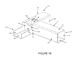
- the retention tabs 6a and 6b are flexed inwardly of the inner surface of the side walls 3a and 3b of the tubular male coupling member 1, conversely to the embodiment illustrated in Figure 1 .
- the a tubular male coupling member of a quadrangular cross section, comprising two retention tabs 6a, 6b (not illustrated) lifted in an angle directed outwardly, each of which placed in each of the respective side walls 3a and 3b of the first end 2a of the a tubular male coupling member 1, and two retention tabs 6c, 6d (not illustrated) lifted also in an angle directed outwardly, placed at the same height of the tabs 6a and 6b (not illustrated), each of which placed in each of the respective upper and lower walls 4a and 4b in the same first end of the a tubular male coupling member 1; and; the tubular female coupling member 10, of a quadrangular cross section, showing a quadrangular retention aperture 15 in an intermediate portion of the side wall 12a of the a tubular female coupling member 10, to be assembled with the a tubular male coupling member 1, in a "T" fashion, constituting another preferred embodiment of the system of Figure 1 , according with the present invention.
- tubular male coupling member could include only one tab lifted outwardly or inwardly; and the tubular female coupling member could include a single slot, to give a required assembling force.
- one of the walls of the a tubular male coupling member could include a first tab in one of its walls and a second tab in an opposite wall, placed opposite to the first tab, both lifted outwardly; and the tubular female coupling member could have a quadrangular aperture, to provide stronger assembling force.
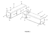
- the parallel transversal slots 14a and 14b ( Figure 1 ) or the quadrangular aperture 15 ( Figure 1C ) are made with means which allow high precision cuts such as a cutter by water jet cutting, oxygen cut , plasma cutting and laser cutting and precision die cut, to mention some of them, in order to obtain precision cuts allowing the insertion of the first and second projections 5a and 5b with very close tolerances which provides an optimum adjustment to the joining.
- the projections and/or the tabs of the tubular male coupling member should be dimensioned such that they could enter into the slots or quadrangular apertures of the tubular female coupling member.
- the retention tabs 6a and 6b of the first and second projections 5a and 5b are formed in said projections by means of a semi quadrangular cut which defines the form of each tab, and afterwards each tab 6a, 6b already formed, is flexed and lifted in an angle directed inwardly or outwardly regarding the plane of the corresponding projections 5a and 5b, such that the retention edge 7a and 7b remain protruded outwardly or inwardly of the a tubular male coupling member 1, so that they locked leaning on the inner edge of the slots 14a and 14b of the tubular female coupling member 10.
- each tab 6a, 6b can include a notch in a central portion of the end thereof in order to introduce a tool there through and facilitate flexing of the tab to a desired position.
- the first and second projections 6a, 6b of the a tubular male coupling member 1 are perpendicularly inserted into the first and second parallel slots 14a, 14b of the a tubular female coupling member 10, such that the retention tab 6a, 6b of each projection 5a, 5b are flexed staying in the same plane as the corresponding projection 5a and 5b, until it completely enters perpendicularly into the parallel slots 14a, 14b of the a tubular female coupling member 10, and turns back by deflection to its lifted or sunken position, such that the retention edge 7a, 7b of each tab 6a, 6b, form a padlock being locked on the inner surface of the inner surface of the first side wall 12a of the a tubular female coupling member 10, as it is shown in Figures 1 , 1A , 1 B, 1C and 1 D , avoiding that the projection 6a, 6b could slide outside of the slot 14a, 14b of the a
- the projections 6a, 6b of the a tubular male coupling member 1 cannot be withdrawn from the a tubular female coupling member 10, they also cannot turn because of the closed tolerance with which they were inserted, because there is no space of "backlash" between the projections 5a and 5b, the parallel transversal slots 14a, 14b and the inner surface of the first side wall 12a of the a tubular female coupling member 10.
- the joining between the a tubular male coupling member 1 and the a tubular female coupling member 10, can or cannot be disassembled, depending of the position and angle of each tab in the moment of the insertion of the projections. In the preferred embodiments of the invention, the joining is permanent.
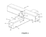
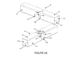
- the tubular female coupling member 40 can include, beside of the slots 43a and 43b and the quadrangular cut 44, a first retention tab 45a and a second retaining tab 45b, both practiced between the slots 43a and 43b, in each lateral wall 41 a and 41 b, starting from the edge of the lower wall 42b to the upper wall 42a, presenting a retention edge 46a and 46b (not illustrated), respectively, staying in this way firmly coupled the tubular male coupling member 20 with the tubular female coupling member 40 in a "+" fashion.
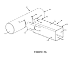
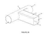
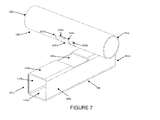
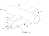
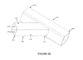
- the snap coupling system between a tubular male coupling member, of a quadrangular cross section, to be coupled in a "T" fashion with a tubular female coupling member, of a circular cross section, of the present invention, this comprises:
- the retention tabs 55a and 55b stay flexed inwardly of the inner surface of the side walls 52a and 52b of the tubular male coupling member 50, inversely from the embodiment illustrated in Figure 3 .
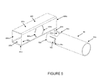
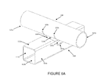
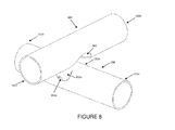
- the snap coupling system between a tubular male coupling member, of a circular cross section, to be assembled in a "T" fashion with a tubular female coupling member, of a circular cross section, of the present invention, this comprises:
- the retention tabs 73a and 73b are flexed inwardly of the inner surface of the tubular male coupling member 70, inversely to the embodiment illustrated in Figure 4 .
- the snap coupling system between tubular male coupling member, of a circular cross section to be assembled in a "T" fashion, with a tubular female coupling member, of quadrangular cross section, of the present invention, this comprises:
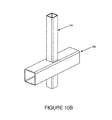
- the snap coupling system between a tubular male coupling member, of a circular cross section, to be assembled in a "+" fashion with a tubular female coupling member, of a quadrangular cross section, of the present invention comprises:
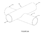
- the snap coupling system between a tubular male coupling member, of a circular cross section, to be assembled in a "+" fashion with a tubular female coupling member, of a circular cross section, of the present invention comprises:
- tubular female coupling member 180 can include a pair of slots (not illustrated) in its side walls 182b to angularly coupling an additional tubular male coupling member, similar and opposite to the 170.
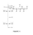
- each retention tab of the tubular male coupling member 190 comprising a first retention tab LR1 starting from an intermediate PI of one of its walls 192a, 192b, 193a, 193b, directed to the first end 191 a of the tubular male coupling member 190, and a second retention tab LR2 starting of the same intermediate portion PI of the same wall as the retention tab LR1, but directed to the end 191 b of the tubular male coupling member 190; both retention tabs LR1 and LR2 being distributed at an space similar to the cross section of the tubular female coupling member 200, such that on passing the tubular male coupling member between the passing through the quadrangular retention aperture 204 of the tubular female coupling member 200, each tab LR1 and LR2 being bilaterally locked both to the first end 191 a, as to the second end 191 b of the tubular male coupling member 190.
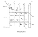
- each of the tubular male coupling member 210 has a retention tab 214a, 216b with its retention edge 215a, 217b, directed to the first end 211a, in its first side wall 212a and a retention wall 214a, 216b, with its retention edge 215a, 217b, in its second side wall 212b, but directed to the second end 211 b, in such a way that each of the tubular male coupling members being retained in both senses by its respective intermediate parts.
- the fence or gate assembled in accordance to the formerly described can comprise a plurality of tubular male coupling members and tubular female coupling members, under the condition that include the tabs and slots corresponding to the number of coupling members.
- tubular female coupling members can be solid of quadrangular or rectangular cross section, as may be the cross section form of the tubular male coupling member.
- tubular male and female coupling members can have a circular cross section.
- tubular female coupling members of the present invention, all of them present at least a flat or curved surface, with its coupling slots at a unique surface, without the rest of the surrounding walls, which could be only a single flat or curved wall.
Landscapes
- Engineering & Computer Science (AREA)
- Architecture (AREA)
- General Engineering & Computer Science (AREA)
- Civil Engineering (AREA)
- Structural Engineering (AREA)
- Mechanical Engineering (AREA)
- Quick-Acting Or Multi-Walled Pipe Joints (AREA)
- Mutual Connection Of Rods And Tubes (AREA)
- Insertion Pins And Rivets (AREA)
- Connection Of Plates (AREA)
Applications Claiming Priority (2)
| Application Number | Priority Date | Filing Date | Title |
|---|---|---|---|
| US12/906,067 US9353546B2 (en) | 2010-10-15 | 2010-10-15 | Snap locking coupling system for pieces or coupling members |
| PCT/MX2011/000123 WO2012050414A2 (es) | 2010-10-15 | 2011-10-12 | Sistema de acoplamiento de enganche a presión entre piezas o miembros de acoplamiento |
Publications (2)
| Publication Number | Publication Date |
|---|---|
| EP2628962A2 true EP2628962A2 (de) | 2013-08-21 |
| EP2628962A4 EP2628962A4 (de) | 2016-08-17 |
Family
ID=45932817
Family Applications (1)
| Application Number | Title | Priority Date | Filing Date |
|---|---|---|---|
| EP11832798.0A Withdrawn EP2628962A4 (de) | 2010-10-15 | 2011-10-12 | Druckkopplungssystem zur verwendung zwischen kopplungselementen oder -teilen |
Country Status (11)
| Country | Link |
|---|---|
| US (2) | US9353546B2 (de) |
| EP (1) | EP2628962A4 (de) |
| JP (1) | JP5947305B2 (de) |
| KR (1) | KR101746897B1 (de) |
| CN (1) | CN103299092A (de) |
| BR (1) | BR112013009140A2 (de) |
| CA (1) | CA2814855C (de) |
| CL (1) | CL2013001045A1 (de) |
| CO (1) | CO6700857A2 (de) |
| MX (1) | MX353050B (de) |
| WO (1) | WO2012050414A2 (de) |
Cited By (1)
| Publication number | Priority date | Publication date | Assignee | Title |
|---|---|---|---|---|
| ES2685267A1 (es) * | 2017-03-31 | 2018-10-08 | Christian GONZÁLEZ IRIARTE | Sistema de retención para uniones |
Families Citing this family (35)
| Publication number | Priority date | Publication date | Assignee | Title |
|---|---|---|---|---|
| CA2669440C (en) | 2009-06-18 | 2019-01-08 | Vision Extrusions Limited | Picket fence |
| US20140034890A1 (en) * | 2012-07-31 | 2014-02-06 | Barrette Outdoor Living, Inc. | Blow molded fencing system |
| JP6119265B2 (ja) * | 2013-01-23 | 2017-04-26 | 沖電気工業株式会社 | 媒体収容装置及び媒体処理装置 |
| AU2014227749C1 (en) * | 2013-03-15 | 2018-04-26 | James E. Green | Self-supporting and load bearing structural joint |
| CN103711762A (zh) * | 2014-01-04 | 2014-04-09 | 李理 | 一种组合式货架的支架连接器 |
| WO2017110601A1 (ja) * | 2015-12-22 | 2017-06-29 | 三菱電機株式会社 | ディスプレイ装置 |
| US11015365B2 (en) * | 2016-09-30 | 2021-05-25 | AP Global Innovations LLC | Fence system and method |
| JP2018105327A (ja) * | 2016-12-22 | 2018-07-05 | 株式会社アマダホールディングス | 接合部材の組合せ方法及び組合せ構造 |
| US10239702B2 (en) * | 2017-01-06 | 2019-03-26 | Roach Manufacturing Corporation | Tubular mezzanine and conveyor support structures and stiffener brackets for assembly thereof |
| CN108283400B (zh) * | 2017-06-07 | 2024-04-05 | 际诺思股份公司 | 一种适用于柱形管体的插接固定结构及床架 |
| CN108286548A (zh) * | 2017-06-07 | 2018-07-17 | 际诺思(厦门)轻工制品有限公司 | 一种适用于多棱柱件的错位插装结构、置物架及组装方法 |
| CN108223523A (zh) * | 2017-06-20 | 2018-06-29 | 际诺思(厦门)轻工制品有限公司 | 一种嵌入式插接结构及桌子 |
| KR102055437B1 (ko) * | 2017-09-22 | 2020-01-23 | 주식회사 더큐브시스템 | 조립식 파이프 결합구조 |
| KR101962885B1 (ko) * | 2017-10-25 | 2019-03-28 | 박종길 | 난간용 조립식 파이프 결합구조 |
| CA3024059A1 (en) | 2017-11-14 | 2019-05-14 | Vision Extrusions Group Limited | Railing system |
| CA3023636A1 (en) | 2017-11-14 | 2019-05-14 | Vision Extrusions Group Limited | Fence panel system |
| CN108237336A (zh) * | 2018-04-09 | 2018-07-03 | 广东泰格威机器人科技有限公司 | 一种用于加强管件焊接的方法及其焊接结构 |
| JP6514814B1 (ja) * | 2018-07-25 | 2019-05-15 | シルックス株式会社 | チューブステントデリバリーシステム |
| KR102120878B1 (ko) * | 2018-12-26 | 2020-06-09 | (주)동광명품도어 | 나사결합식 무용접 프레임 조립구조 |
| KR102209278B1 (ko) * | 2019-05-03 | 2021-01-28 | 신영환 | 이동식 천막 구조물 |
| EP3981071B1 (de) * | 2019-06-10 | 2024-08-28 | Origami Solar, Inc. | Verfahren und systeme für solarpaneele mit gefaltetem rahmen |
| KR102264186B1 (ko) * | 2019-09-02 | 2021-06-11 | 윤희남 | 화단겸용담장 |
| KR102125654B1 (ko) * | 2019-11-06 | 2020-07-07 | 한지현 | 파이프 조인트 및 이를 사용한 파이프 조립물 |
| US11585114B2 (en) * | 2020-03-30 | 2023-02-21 | Andrew Row Smith | Fence rail fork |
| US11542721B2 (en) | 2020-06-08 | 2023-01-03 | Origin Point Brands, Llc | Prefabricated modular fencing with advantageously-shaped connectors |
| CN112780648B (zh) * | 2020-12-30 | 2024-08-02 | 黄建华 | 矩形管固定结构 |
| MX2021011602A (es) * | 2021-09-23 | 2023-03-24 | Eduardo Calderon Abad | Tejido plastico de ensamble rotativo. |
| US12416152B2 (en) * | 2021-11-12 | 2025-09-16 | Arktura Llc | Architectural fixture connection system |
| CN113982297B (zh) * | 2021-12-02 | 2023-03-14 | 中国十七冶集团有限公司 | 一种建筑安全预警用智能防护装置及防护网安装方法 |
| KR102699012B1 (ko) * | 2022-06-08 | 2024-08-26 | 주식회사 동희산업 | 차량용 서브프레임 |
| US20240229479A1 (en) * | 2023-01-10 | 2024-07-11 | Greg Hyde HRYNIEWICZ | Framing system including tubes joined with slots, hooks and wedges integrated into the tubes |
| TWI831726B (zh) * | 2023-09-06 | 2024-02-01 | 廈興國際股份有限公司 | 籬笆的邊柱結構改良 |
| TWI831728B (zh) * | 2023-09-19 | 2024-02-01 | 廈興國際股份有限公司 | 護欄的直桿與橫桿結合結構 |
| TWI844504B (zh) * | 2024-01-18 | 2024-06-01 | 廈興國際股份有限公司 | 護欄的直桿與橫桿結合結構 |
| JP7583979B2 (ja) * | 2023-12-22 | 2024-11-15 | Wachstum株式会社 | 部材の接合構造および構造体 |
Family Cites Families (27)
| Publication number | Priority date | Publication date | Assignee | Title |
|---|---|---|---|---|
| US562067A (en) * | 1896-06-16 | Frame for velocipedes | ||
| US603224A (en) * | 1898-04-26 | platt | ||
| US2846241A (en) * | 1953-08-24 | 1958-08-05 | Gen Motors Corp | Pipe end to pipe side joint |
| US2869694A (en) * | 1954-07-23 | 1959-01-20 | Air Filter Corp | Frame construction for filter units |
| US3009719A (en) * | 1959-06-19 | 1961-11-21 | Aluminum Extrusions Inc | Locking mortise and tenon joint |
| US3746379A (en) * | 1971-09-09 | 1973-07-17 | Flangeklamp Corp | Locking connection for supporting grid systems |
| US3748814A (en) * | 1971-09-16 | 1973-07-31 | Capitol Prod Corp | Decorative metal grid system for windows |
| US3822053A (en) * | 1971-12-16 | 1974-07-02 | Daily Corp | Tubular picket fence |
| US4034534A (en) * | 1973-04-30 | 1977-07-12 | Intalite International | Louvered ceiling |
| US3927950A (en) * | 1975-01-24 | 1975-12-23 | G S Beckwith Gilbert | Half-lapped tube joint |
| US4007919A (en) * | 1975-07-24 | 1977-02-15 | Totten Clyde D | Fence structure |
| CA1089422A (en) * | 1977-10-24 | 1980-11-11 | Allan T. Bishop | Door panel for mail box unit |
| US4145858A (en) * | 1977-11-03 | 1979-03-27 | Nathan Dovman | Window grille construction |
| US4479737A (en) * | 1982-02-01 | 1984-10-30 | Bergh Bros. Co., Inc. | Positive interlock |
| JPS6099606U (ja) * | 1983-11-24 | 1985-07-06 | 山崎 慶市郎 | 手摺等の接合構造 |
| US4596104A (en) * | 1984-10-18 | 1986-06-24 | Keiichiro Yamazaki | Joint structure for a structural bar assembly |
| GB2174783A (en) * | 1985-05-01 | 1986-11-12 | Abacus Municipal Ltd | Jointing system |
| JPS6446353U (de) * | 1987-09-18 | 1989-03-22 | ||
| JPH0542182Y2 (de) * | 1988-05-12 | 1993-10-25 | ||
| JPH0545693Y2 (de) * | 1988-05-12 | 1993-11-25 | ||
| JPH0542183Y2 (de) * | 1988-06-01 | 1993-10-25 | ||
| US5018332A (en) * | 1989-05-11 | 1991-05-28 | Ying Kit Choi | Grating |
| US5249818A (en) * | 1991-07-26 | 1993-10-05 | Cannondale Corporation | Method of making frames from tubular members and frames made by the method |
| US5190207A (en) * | 1992-06-02 | 1993-03-02 | Deere & Company | Method for welding rectangular tubes |
| CN1617969A (zh) * | 2001-12-18 | 2005-05-18 | 沃尔特·曼弗雷德·库尼茨 | 栅栏装置 |
| FR2839101B1 (fr) * | 2002-04-24 | 2005-09-16 | Rienzo Jean Pierre Di | Element de barriere a montage simplifiee, barriere comprenant un tel element et procede d'assemblage d'un tel element |
| JP4170373B2 (ja) * | 2007-08-24 | 2008-10-22 | 株式会社オノックスエムティーティー | 角パイプの構造体 |
-
2010
- 2010-10-15 US US12/906,067 patent/US9353546B2/en not_active Expired - Fee Related
-
2011
- 2011-08-10 MX MX2011008420A patent/MX353050B/es active IP Right Grant
- 2011-10-12 EP EP11832798.0A patent/EP2628962A4/de not_active Withdrawn
- 2011-10-12 KR KR1020137012437A patent/KR101746897B1/ko active Active
- 2011-10-12 BR BR112013009140A patent/BR112013009140A2/pt not_active Application Discontinuation
- 2011-10-12 WO PCT/MX2011/000123 patent/WO2012050414A2/es not_active Ceased
- 2011-10-12 CA CA2814855A patent/CA2814855C/en active Active
- 2011-10-12 CN CN2011800607593A patent/CN103299092A/zh active Pending
- 2011-10-12 JP JP2013533786A patent/JP5947305B2/ja not_active Expired - Fee Related
-
2013
- 2013-04-15 CO CO13096799A patent/CO6700857A2/es unknown
- 2013-04-15 CL CL2013001045A patent/CL2013001045A1/es unknown
-
2016
- 2016-04-29 US US15/142,314 patent/US10458147B2/en active Active
Cited By (1)
| Publication number | Priority date | Publication date | Assignee | Title |
|---|---|---|---|---|
| ES2685267A1 (es) * | 2017-03-31 | 2018-10-08 | Christian GONZÁLEZ IRIARTE | Sistema de retención para uniones |
Also Published As
| Publication number | Publication date |
|---|---|
| CA2814855C (en) | 2015-04-07 |
| WO2012050414A2 (es) | 2012-04-19 |
| MX353050B (es) | 2017-12-06 |
| WO2012050414A3 (es) | 2012-08-02 |
| CL2013001045A1 (es) | 2014-04-11 |
| EP2628962A4 (de) | 2016-08-17 |
| JP5947305B2 (ja) | 2016-07-06 |
| US20160244991A1 (en) | 2016-08-25 |
| KR101746897B1 (ko) | 2017-06-14 |
| JP2013540970A (ja) | 2013-11-07 |
| US10458147B2 (en) | 2019-10-29 |
| CN103299092A (zh) | 2013-09-11 |
| BR112013009140A2 (pt) | 2019-05-07 |
| CA2814855A1 (en) | 2012-04-19 |
| US9353546B2 (en) | 2016-05-31 |
| KR20140021519A (ko) | 2014-02-20 |
| US20120090140A1 (en) | 2012-04-19 |
| MX2011008420A (es) | 2012-04-16 |
| CO6700857A2 (es) | 2013-06-28 |
Similar Documents
| Publication | Publication Date | Title |
|---|---|---|
| EP2628962A2 (de) | Druckkopplungssystem zur verwendung zwischen kopplungselementen oder -teilen | |
| US4099887A (en) | Structural joints | |
| US4544069A (en) | Modular elements for composing frames for the construction of cabinet structures and containers for electrical, electromechanical and electronic components, for internal and external use | |
| CA2496475A1 (en) | Connecting device | |
| US20180305924A1 (en) | Interlocking panels | |
| US4221038A (en) | Method for forming a frame | |
| US8381478B2 (en) | Retaining wall block | |
| KR101762194B1 (ko) | 절곡조립식 창틀 및 창호 조립구조 | |
| SK500182020U1 (sk) | Stavebnica so základným prvkom a spojovacím kolíkom | |
| JP2012241835A (ja) | 角パイプの直交連結構造 | |
| EP1775481B1 (de) | Verbindungsstruktur für Rohre | |
| US20140013663A1 (en) | Modular planter box | |
| CN110475979A (zh) | 用于联结的保持系统 | |
| US12146312B2 (en) | Modular building system | |
| GB2379257A (en) | Tube joints | |
| JP7213496B2 (ja) | 棒状体固定構造とそれを用いた搬送容器 | |
| HK1188477A (en) | Pressure-coupling system for use between coupling members or parts | |
| JP7249651B2 (ja) | 接合部材の製造方法、接合部材、及び、骨組み構造体 | |
| EP1181695B1 (de) | Behälter für kernbrennelemente | |
| US20240229479A1 (en) | Framing system including tubes joined with slots, hooks and wedges integrated into the tubes | |
| WO2002018724A8 (fr) | Assemblage d'elements verriers | |
| CA2751120A1 (en) | Slide corner connector for flange | |
| WO2019220116A1 (en) | Modular frame | |
| KR102622505B1 (ko) | 다축으로 결합되는 파이프 구조 | |
| JPH0547204Y2 (de) |
Legal Events
| Date | Code | Title | Description |
|---|---|---|---|
| PUAI | Public reference made under article 153(3) epc to a published international application that has entered the european phase |
Free format text: ORIGINAL CODE: 0009012 |
|
| 17P | Request for examination filed |
Effective date: 20130416 |
|
| AK | Designated contracting states |
Kind code of ref document: A2 Designated state(s): AL AT BE BG CH CY CZ DE DK EE ES FI FR GB GR HR HU IE IS IT LI LT LU LV MC MK MT NL NO PL PT RO RS SE SI SK SM TR |
|
| DAX | Request for extension of the european patent (deleted) | ||
| A4 | Supplementary search report drawn up and despatched |
Effective date: 20160720 |
|
| RIC1 | Information provided on ipc code assigned before grant |
Ipc: E04H 17/14 20060101ALI20160714BHEP Ipc: F16B 7/04 20060101AFI20160714BHEP Ipc: F16B 21/08 20060101ALI20160714BHEP Ipc: E04F 11/18 20060101ALI20160714BHEP |
|
| STAA | Information on the status of an ep patent application or granted ep patent |
Free format text: STATUS: REQUEST FOR EXAMINATION WAS MADE |
|
| STAA | Information on the status of an ep patent application or granted ep patent |
Free format text: STATUS: THE APPLICATION IS DEEMED TO BE WITHDRAWN |
|
| 18D | Application deemed to be withdrawn |
Effective date: 20200603 |