EP2628693B1 - Adapter für Sprühdosen - Google Patents
Adapter für Sprühdosen Download PDFInfo
- Publication number
- EP2628693B1 EP2628693B1 EP12178775.8A EP12178775A EP2628693B1 EP 2628693 B1 EP2628693 B1 EP 2628693B1 EP 12178775 A EP12178775 A EP 12178775A EP 2628693 B1 EP2628693 B1 EP 2628693B1
- Authority
- EP
- European Patent Office
- Prior art keywords
- nozzle
- adaptor
- cylindrical
- holder
- connector
- Prior art date
- Legal status (The legal status is an assumption and is not a legal conclusion. Google has not performed a legal analysis and makes no representation as to the accuracy of the status listed.)
- Active
Links
Images


Classifications
-
- B—PERFORMING OPERATIONS; TRANSPORTING
- B65—CONVEYING; PACKING; STORING; HANDLING THIN OR FILAMENTARY MATERIAL
- B65D—CONTAINERS FOR STORAGE OR TRANSPORT OF ARTICLES OR MATERIALS, e.g. BAGS, BARRELS, BOTTLES, BOXES, CANS, CARTONS, CRATES, DRUMS, JARS, TANKS, HOPPERS, FORWARDING CONTAINERS; ACCESSORIES, CLOSURES, OR FITTINGS THEREFOR; PACKAGING ELEMENTS; PACKAGES
- B65D83/00—Containers or packages with special means for dispensing contents
- B65D83/14—Containers for dispensing liquid or semi-liquid contents by internal gaseous pressure, i.e. aerosol containers comprising propellant
- B65D83/28—Nozzles, nozzle fittings or accessories specially adapted therefor
- B65D83/30—Nozzles, nozzle fittings or accessories specially adapted therefor for guiding the flow of the dispensed content, e.g. funnels or hoods
-
- B—PERFORMING OPERATIONS; TRANSPORTING
- B05—SPRAYING OR ATOMISING IN GENERAL; APPLYING FLUENT MATERIALS TO SURFACES, IN GENERAL
- B05B—SPRAYING APPARATUS; ATOMISING APPARATUS; NOZZLES
- B05B1/00—Nozzles, spray heads or other outlets, with or without auxiliary devices such as valves, heating means
- B05B1/14—Nozzles, spray heads or other outlets, with or without auxiliary devices such as valves, heating means with multiple outlet openings; with strainers in or outside the outlet opening
- B05B1/16—Nozzles, spray heads or other outlets, with or without auxiliary devices such as valves, heating means with multiple outlet openings; with strainers in or outside the outlet opening having selectively- effective outlets
- B05B1/1627—Nozzles, spray heads or other outlets, with or without auxiliary devices such as valves, heating means with multiple outlet openings; with strainers in or outside the outlet opening having selectively- effective outlets with a selecting mechanism comprising a gate valve, a sliding valve or a cock
- B05B1/1636—Nozzles, spray heads or other outlets, with or without auxiliary devices such as valves, heating means with multiple outlet openings; with strainers in or outside the outlet opening having selectively- effective outlets with a selecting mechanism comprising a gate valve, a sliding valve or a cock by relative rotative movement of the valve elements
- B05B1/1645—Nozzles, spray heads or other outlets, with or without auxiliary devices such as valves, heating means with multiple outlet openings; with strainers in or outside the outlet opening having selectively- effective outlets with a selecting mechanism comprising a gate valve, a sliding valve or a cock by relative rotative movement of the valve elements the outlets being rotated during selection
-
- B—PERFORMING OPERATIONS; TRANSPORTING
- B05—SPRAYING OR ATOMISING IN GENERAL; APPLYING FLUENT MATERIALS TO SURFACES, IN GENERAL
- B05B—SPRAYING APPARATUS; ATOMISING APPARATUS; NOZZLES
- B05B1/00—Nozzles, spray heads or other outlets, with or without auxiliary devices such as valves, heating means
- B05B1/14—Nozzles, spray heads or other outlets, with or without auxiliary devices such as valves, heating means with multiple outlet openings; with strainers in or outside the outlet opening
- B05B1/16—Nozzles, spray heads or other outlets, with or without auxiliary devices such as valves, heating means with multiple outlet openings; with strainers in or outside the outlet opening having selectively- effective outlets
- B05B1/169—Nozzles, spray heads or other outlets, with or without auxiliary devices such as valves, heating means with multiple outlet openings; with strainers in or outside the outlet opening having selectively- effective outlets having three or more selectively effective outlets
-
- B—PERFORMING OPERATIONS; TRANSPORTING
- B05—SPRAYING OR ATOMISING IN GENERAL; APPLYING FLUENT MATERIALS TO SURFACES, IN GENERAL
- B05B—SPRAYING APPARATUS; ATOMISING APPARATUS; NOZZLES
- B05B11/00—Single-unit hand-held apparatus in which flow of contents is produced by the muscular force of the operator at the moment of use
- B05B11/0005—Components or details
- B05B11/0027—Means for neutralising the actuation of the sprayer ; Means for preventing access to the sprayer actuation means
- B05B11/0029—Valves not actuated by pressure
-
- B—PERFORMING OPERATIONS; TRANSPORTING
- B05—SPRAYING OR ATOMISING IN GENERAL; APPLYING FLUENT MATERIALS TO SURFACES, IN GENERAL
- B05B—SPRAYING APPARATUS; ATOMISING APPARATUS; NOZZLES
- B05B15/00—Details of spraying plant or spraying apparatus not otherwise provided for; Accessories
- B05B15/60—Arrangements for mounting, supporting or holding spraying apparatus
- B05B15/65—Mounting arrangements for fluid connection of the spraying apparatus or its outlets to flow conduits
- B05B15/658—Mounting arrangements for fluid connection of the spraying apparatus or its outlets to flow conduits the spraying apparatus or its outlet axis being perpendicular to the flow conduit
-
- B—PERFORMING OPERATIONS; TRANSPORTING
- B65—CONVEYING; PACKING; STORING; HANDLING THIN OR FILAMENTARY MATERIAL
- B65D—CONTAINERS FOR STORAGE OR TRANSPORT OF ARTICLES OR MATERIALS, e.g. BAGS, BARRELS, BOTTLES, BOXES, CANS, CARTONS, CRATES, DRUMS, JARS, TANKS, HOPPERS, FORWARDING CONTAINERS; ACCESSORIES, CLOSURES, OR FITTINGS THEREFOR; PACKAGING ELEMENTS; PACKAGES
- B65D83/00—Containers or packages with special means for dispensing contents
- B65D83/14—Containers for dispensing liquid or semi-liquid contents by internal gaseous pressure, i.e. aerosol containers comprising propellant
- B65D83/16—Actuating means
- B65D83/164—Actuators comprising a manually operated valve and being attachable to the aerosol container, e.g. downstream a valve fitted to the container; Actuators associated to container valves with valve seats located outside the aerosol container
-
- B—PERFORMING OPERATIONS; TRANSPORTING
- B65—CONVEYING; PACKING; STORING; HANDLING THIN OR FILAMENTARY MATERIAL
- B65D—CONTAINERS FOR STORAGE OR TRANSPORT OF ARTICLES OR MATERIALS, e.g. BAGS, BARRELS, BOTTLES, BOXES, CANS, CARTONS, CRATES, DRUMS, JARS, TANKS, HOPPERS, FORWARDING CONTAINERS; ACCESSORIES, CLOSURES, OR FITTINGS THEREFOR; PACKAGING ELEMENTS; PACKAGES
- B65D83/00—Containers or packages with special means for dispensing contents
- B65D83/14—Containers for dispensing liquid or semi-liquid contents by internal gaseous pressure, i.e. aerosol containers comprising propellant
- B65D83/16—Actuating means
- B65D83/20—Actuator caps
-
- B—PERFORMING OPERATIONS; TRANSPORTING
- B65—CONVEYING; PACKING; STORING; HANDLING THIN OR FILAMENTARY MATERIAL
- B65D—CONTAINERS FOR STORAGE OR TRANSPORT OF ARTICLES OR MATERIALS, e.g. BAGS, BARRELS, BOTTLES, BOXES, CANS, CARTONS, CRATES, DRUMS, JARS, TANKS, HOPPERS, FORWARDING CONTAINERS; ACCESSORIES, CLOSURES, OR FITTINGS THEREFOR; PACKAGING ELEMENTS; PACKAGES
- B65D83/00—Containers or packages with special means for dispensing contents
- B65D83/14—Containers for dispensing liquid or semi-liquid contents by internal gaseous pressure, i.e. aerosol containers comprising propellant
- B65D83/28—Nozzles, nozzle fittings or accessories specially adapted therefor
- B65D83/30—Nozzles, nozzle fittings or accessories specially adapted therefor for guiding the flow of the dispensed content, e.g. funnels or hoods
- B65D83/303—Nozzles, nozzle fittings or accessories specially adapted therefor for guiding the flow of the dispensed content, e.g. funnels or hoods using extension tubes located in or at the nozzle outlets
-
- B—PERFORMING OPERATIONS; TRANSPORTING
- B65—CONVEYING; PACKING; STORING; HANDLING THIN OR FILAMENTARY MATERIAL
- B65D—CONTAINERS FOR STORAGE OR TRANSPORT OF ARTICLES OR MATERIALS, e.g. BAGS, BARRELS, BOTTLES, BOXES, CANS, CARTONS, CRATES, DRUMS, JARS, TANKS, HOPPERS, FORWARDING CONTAINERS; ACCESSORIES, CLOSURES, OR FITTINGS THEREFOR; PACKAGING ELEMENTS; PACKAGES
- B65D83/00—Containers or packages with special means for dispensing contents
- B65D83/14—Containers for dispensing liquid or semi-liquid contents by internal gaseous pressure, i.e. aerosol containers comprising propellant
- B65D83/56—Containers for dispensing liquid or semi-liquid contents by internal gaseous pressure, i.e. aerosol containers comprising propellant with arrangements for interruption of dispensing when the container is inverted
-
- B—PERFORMING OPERATIONS; TRANSPORTING
- B65—CONVEYING; PACKING; STORING; HANDLING THIN OR FILAMENTARY MATERIAL
- B65D—CONTAINERS FOR STORAGE OR TRANSPORT OF ARTICLES OR MATERIALS, e.g. BAGS, BARRELS, BOTTLES, BOXES, CANS, CARTONS, CRATES, DRUMS, JARS, TANKS, HOPPERS, FORWARDING CONTAINERS; ACCESSORIES, CLOSURES, OR FITTINGS THEREFOR; PACKAGING ELEMENTS; PACKAGES
- B65D83/00—Containers or packages with special means for dispensing contents
- B65D83/14—Containers for dispensing liquid or semi-liquid contents by internal gaseous pressure, i.e. aerosol containers comprising propellant
- B65D83/567—Containers for dispensing liquid or semi-liquid contents by internal gaseous pressure, i.e. aerosol containers comprising propellant with means for preventing delivery
-
- F—MECHANICAL ENGINEERING; LIGHTING; HEATING; WEAPONS; BLASTING
- F16—ENGINEERING ELEMENTS AND UNITS; GENERAL MEASURES FOR PRODUCING AND MAINTAINING EFFECTIVE FUNCTIONING OF MACHINES OR INSTALLATIONS; THERMAL INSULATION IN GENERAL
- F16N—LUBRICATING
- F16N3/00—Devices for supplying lubricant by manual action
- F16N3/02—Devices for supplying lubricant by manual action delivering oil
- F16N3/04—Oil cans; Oil syringes
- F16N3/06—Oil cans; Oil syringes delivering on squeezing
-
- F—MECHANICAL ENGINEERING; LIGHTING; HEATING; WEAPONS; BLASTING
- F16—ENGINEERING ELEMENTS AND UNITS; GENERAL MEASURES FOR PRODUCING AND MAINTAINING EFFECTIVE FUNCTIONING OF MACHINES OR INSTALLATIONS; THERMAL INSULATION IN GENERAL
- F16N—LUBRICATING
- F16N21/00—Conduits; Junctions; Fittings for lubrication apertures
- F16N21/04—Nozzles for connection of lubricating equipment to nipples
-
- F—MECHANICAL ENGINEERING; LIGHTING; HEATING; WEAPONS; BLASTING
- F16—ENGINEERING ELEMENTS AND UNITS; GENERAL MEASURES FOR PRODUCING AND MAINTAINING EFFECTIVE FUNCTIONING OF MACHINES OR INSTALLATIONS; THERMAL INSULATION IN GENERAL
- F16N—LUBRICATING
- F16N25/00—Distributing equipment with or without proportioning devices
Definitions
- the present invention relates to an adaptor for spray cans.
- dental instruments such as, merely by way of example, turbines and contra-angles, require lubrication of all the moving parts at least daily and in any case, always before sterilisation.
- Such instruments are generally provided with a special aperture which the nozzle of a spray can of appropriate lubricant can be inserted in.
- JP 10 014949 A discloses a dispensing device for a container of a washing liquid containing a foaming component that requires turning upside-down the container to dispense the liquid.
- the problem which the present invention sets out to resolve is that of making a system available which overcomes the drawbacks spoken of above.
- One object of the invention is therefore an adaptor for spray cans which has a plurality of dispenser nozzles, each suitable for application to various mechanical instruments.
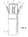
- the adaptor according to the invention comprises a body 2 to which a plurality of nozzle-holders 3 may be joined, an actuator 4 for operating the dispenser of a spray can (indicted by B in figure 8 ) and a closure cap 5.
- the body 2 can be inscribed in a cylinder or in a truncated cone and is hollow so as to form a cylindrical channel 8 which runs longitudinally all along the body 2.
- the body 2 comprises a base portion 6 and an upper cylindrical portion 7 having a diameter less than that of the base portion 6 so as to form a shoulder 6a with it.
- a plurality of parallel pairs of fins spread out in a fan shape from the cylindrical portion 7.
- the fins 9 extend in height all along the cylindrical portion 7 and in depth as far as connecting to the rim of the base 6, so as to define one or more sectors 11, each positioned between a pair of parallel fins 9, alternated with two or more V-shaped sectors 10.
- each sector 11 positioned between the pairs of parallel fins 9 each form a seat for housing a nozzle-holder 3.
- the lower portion of each sector 11 comprises, along the fins 9, two hook elements 9a. It also has, along the rim of the shoulder 6a, a notch 14, the function of which will be clear from the rest of the description.
- each sector 11 further comprises, on the surface of the cylindrical portion 7 of the body 2, a hole 12 which places the outside in communication with the cylindrical channel 8 inside the body 2.
- a hole 12 which places the outside in communication with the cylindrical channel 8 inside the body 2.
- an annular seat 13 is placed for a gasket 13', generally an O-ring in elastomeric material.
- the surface of the shoulder 6a comprises a notch 14', the function of which will be clear from the rest of the description.
- the base portion of the body 2 further comprises, along the lower rim of the cylindrical channel 8, coupling means 32 to the neck of a spray can B.
- such coupling means 32 are composed of a plurality of teeth suitable for snap-catching to the rim of the neck of a can.
- these may consist of a magnetic ring suitable for magnetically coupling to said rim of the can, generally made in ferrous material.
- the nozzle-holder 3 comprises a coupling portion 15 to the hook elements 9a joined to the parallel fins 9 and a connector portion 16.
- the coupling portion 15 is a substantially cylindrical shape and comprises, at the two sides, two pins 17 destined to couple to the hook elements 9a.
- the coupling portion 15 further comprises a tooth 18, which extends from the cylindrical surface of the coupling portion 15, such tooth 18 being destined to facilitate the lowering of the nozzle-holder 3 from the closed to the operating position - constituting a gripping surface for the finger of a user - and to sustain and stop the nozzle-holder 3 at 90° from the vertical when in the operating position.
- the connector portion 16 is a substantially cylindrical shape and extends starting from the cylindrical surface of the coupling portion 15, in an adjacent position to the tooth 18.
- the connector portion 16 comprises a threading 50 for a stable coupling with a nozzle U, in turn fitted with a complementary threading on its inner surface.
- the nozzle-holder 3 is hollow and comprises internally a channel which connects the aperture 19 of the connector portion 16 to a hole 20 positioned on the coupling portion in alignment with said aperture 19.
- the cylindrical channel 8 of the body 2 is in flow communication with the outside and the adaptor 1 according to the invention is placed in an operating condition.
- the nozzle-holder 3 is made to rotate so that the connector portion 16 is facing upwards, the hole 12 of the body 2 and the hole 20 of the nozzle-holder become misaligned, interrupting the flow communication between the inside and the outside of the body 2.
- the gasket 13' ensures a seal against the cylindrical surface of the coupling portion 15 of the nozzle-holder 3 at all times, while the connector portion 16 is enclosed between the fins 9, minimising obstruction.
- the notch 14 acts as a drainage channel and ensures the outflow of the residual lubricant oil inside the nozzle-holder 3 and in the nozzle U (lubricant oil which remains inside the nozzle-holder after dispensing) downwards.
- the lower side of the base portion 6, that is the side opposite the shoulder 6a can house a ring of absorbent material (not shown), such as a ring of foam rubber, felt or other material, having the function of absorbing the lubricant oil dripping from the nozzle-holder 3 after each use.
- a ring of absorbent material such as a ring of foam rubber, felt or other material, having the function of absorbing the lubricant oil dripping from the nozzle-holder 3 after each use.
- the actuator 4 has an outer diameter such as to be inserted so as to slide inside the cylindrical channel 8 of the body 2.
- the actuator 4 comprises a central portion 21, which in turn comprises a button portion 22 at one end and a distal portion 23 at the opposite end.
- the central portion 21 is substantially inscribable in a cylinder and comprises two end discs 21a, 21b connected by a central stem 24 and by ribs 25 (four in the drawing) which extend from the stem 24 as far as the perimeter of the two end discs 21a, 21b.
- This structure makes it possible to lighten the central portion 21, saving material, without however jeopardising the rigidity of the structure.
- the button portion 22 also a substantially cylindrical shape, has a smaller diameter than that of the end disc 21a it is joined to, so as to form a recessed rim 26.
- the distal portion 23 extends from the lower terminal disc 21b with a slightly smaller diameter than that of the disc 21b and ends in a beak 27.
- the distal portion 23 comprises a duct 28 which ends underneath in the beak 27 with an engagement aperture 29 with the nozzle of the can B.
- the duct 28 ends at the opposite end with an orifice 30 positioned on the cylindrical surface of the distal portion 23.
- gaskets 31', 31" On the cylindrical surface of the distal portion 23 two gaskets 31', 31" a r e also positioned, longitudinally distanced so as to enclose between them the orifice 30 and such as to interfere with the surface of the cylindrical channel 8 so as to seal it.
- An annular channel 33 is thereby formed between the two gaskets 31', 31".
- the gaskets 31', 31" may typically be O-rings in elastomeric material.
- the orifice 30 is positioned at a distance from the aperture 29 such that, when the actuator 4 is inserted in the cylindrical channel 8 of the body 2 and is pressed to operate the spray can, the annular channel 33 will be level with the apertures 12 of the various sectors 11.
- a spring 40 preferably a helical spring, which presses on one side on the lower surface of the distal portion 23 and on the other on the upper surface of the inner rim 166 of the body 2 is positioned around the beak 27.
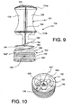
- the actuator 104 comprises two separate parts, that is a mobile pusher 151 and a fixed dispenser connector 152. Both have an outer diameter such as to be inserted so as to slide inside the cylindrical channel 8 of the body 2.
- the pusher 151 is substantially inscribable in a cylinder and comprises two end discs 121a, 121b connected by a central stem 124 and by ribs 125 (four in the drawing) which extend from the stem 124 as far as the perimeter of the two end discs 121a, 121b.
- a button portion 122 is positioned above the upper end disc 121a.
- the button portion 122 also a substantially cylindrical shape, has a smaller diameter than that of the end disc 121a it is joined to, so as to form a recessed rim 126.
- the central stem 124 extends, under the lower end disc 121b, to form a thrust finger 153, the lower end 154 of which is a convex shape.
- the dispenser connector 152 is slightly smaller in diameter than the end disc 121b and is a cylindrical shape with an inner cavity 155, open at both ends.
- a connector element 156 destined to engage with the nozzle of the can B is positioned in a central position inside the cavity 155.
- the connector element 156 comprises an aperture 157 on the side facing downwards, which the nozzle of the can B is inserted in.
- the aperture 157 is surrounded by a flared rim 158.
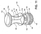
- the connector element 156 On the opposite side, facing upwards, the connector element 156 has a closed surface 159.
- the pusher 151 presses on such closed surface 159.
- the surface 159 is preferably concave, so as to achieve a shaped coupling with the convex surface of the lower end 154 of the pusher 151.
- both the lower end 154 of the pusher 151 and the closed surface 159 of the connector element 156 will however be possible to configure both the lower end 154 of the pusher 151 and the closed surface 159 of the connector element 156 differently, for example envisaging flat surfaces.
- the connector element 156 is connected to the inner cylindrical surface 160 of the dispenser connector 152 by means of a peduncle 161.
- a duct 128 which originates from the aperture 157 of the connector element 156 and ends at the opposite end with an orifice 130 positioned on the outer cylindrical surface of the dispenser connector 152 is housed.
- Annular grooves 162', 162" are also positioned on the cylindrical outer surface of the dispenser connector 152, the grooves being destined to house two gaskets (not shown), longitudinally distanced so as to enclose between them the orifice 130 and such as to interfere with the surface of the cylindrical channel 8 so as to seal it.
- the gaskets may typically be O-rings in elastomeric material.
- the orifice 130 is in turn positioned on the bottom of an annular groove 133.
- the annular groove 133 which houses the orifice 130 is positioned level with the apertures 12 of the various sectors 11, so that, when the device is actuated, the lubricant liquid vaporised by the can B passes through the duct 128 and to the orifice 130 and can be dispensed through the selected nozzle-holder 3.
- the upper rim 163 of the dispenser connector 152 is configured in such a way as to act as an abutment surface for the pusher 151, thereby limiting its downward stroke. Excessive pressure could in fact damage or break the peduncle 161.
- the dispenser connector 152 or at least the peduncle 161 is made in a sufficiently flexible material as to permit the flexion of the peduncle when the pressure of a finger is applied to the button portion 122 of the pusher 151.
- the dispenser connector 152 may be made in a plastic material such as polypropylene.
- Elastic means 164 are positioned between the pusher 151 and the dispenser connector 152 to permit the upward return of the pusher 151.
- the elastic means 164 press on a shoulder 165 positioned at the bottom of the upper rim 163 of the dispenser connector 152 and on the lower surface of the pusher 151.
- the closure cap 5 comprises an upper portion 34, from the perimeter of which a plurality of tabs 36 extend downwards. Each tab 36 terminates at the bottom with a tooth 37 of a size and shape as to be inserted in a notch 14' present in each of the V-shaped sectors 10 of the body 2. The space separating one tab 36 from that adjacent to it corresponds rather to the extension in width of a sector 11 of the body 2.
- the upper portion 34 of the closure cap 5 has a central hole 35 of such diameter as to permit the introduction of the button portion 22, 122 of the actuator 4 and such as to constitute a stop for the recessed rim 26, 126.
- the adaptor 1 is assembled by introducing the actuator 4 inside the cylindrical channel 8 of the body 2 and positioning above it the closure cap 5 until the teeth 37 snap into the respective notches 14'.
- the actuator 4 is in turn assembled by first introducing the dispenser connector 152 in the cylindrical channel 8 until it abuts with the inner rim 166 (see figure 3 ) of the body 2; the elastic means 164 are then positioned and lastly the pusher 151 is introduced.
- the cap 5 may be attached to the body 2 by chemical (glues) or mechanical means (such as ultrasound soldering for example). This way, the closure cap 5 presses upwards against the recessed rim 26, 126 of the actuator 4, preventing it from being extracted from above. Before or after such operation, the nozzle-holder 3 can be fitted in the respective seats of the sector 11 as described above.
- the adaptor 1 functions as follows:
- the adaptor 1 is fitted onto a can B ( Figure 8 ) in such a way that the coupling means 32 block it to the neck of the can.
- the beak 27 or, in the embodiment shown in figures 9-11 the connector element 156 of the actuator 4 will be joined to the dispenser nozzle of the can (not shown) without however exerting a dispensing pressure on it.
- the button portion 22, 122 of the actuator 4 must be pressed. The return of the actuator 4 to the rest position is ensured by the same dispenser nozzle of the can and by the spring 40 or by the elastic means 164.
- the nozzle-holder 3 To achieve the dispensing of the spray from one of the nozzle-holders, the nozzle-holder 3 must however be placed in the operating condition, that is to say in a position in which the connector portion 16 is horizontal and the hole 20 of the coupling portion 15 is aligned with the hole 12 of the body 2.
- the actuator 4 when the actuator 4 is pressed to dispense the spray, the fluid passes through the duct 28, 128 and the orifice 30, 130 until it reaches the annular channel 33,133, from which it passes into the nozzle-holder 3 which is positioned in an operative condition.
- gaskets 31', 31" or, in the embodiment in figures 9-11 , the gaskets housed in the annular grooves 162', 162", prevent the exit of the fluid from the annular channel 33, 133 while the gaskets 13 of the other non-selected holes 12 prevent the exit of fluid outwards.
- a nozzle U may be fitted suitable for the various devices to be serviced.
- the various nozzles U may be different colours, so as to facilitate the selection of the nozzle U suitable for the specific instrument to be lubricated.
- nozzles for dispensing the fluid, typically a lubricant, in different models and brands of instrument.
- nozzles may be pre-fitted to respective nozzle-holders 3, thereby saving time and cost to the user.
- the latter in fact will not need to have a number of cans available, each with a different nozzle, or instead have to attach and detach different nozzles to the same can as required.
- the adaptor according to the invention may be made in plastic with a consequent low production cost.
- the adaptor according to the invention has been designed in particular for use in lubricating dental instruments, it is clear that it may also be applied to all those mechanical instruments which require this type of maintenance, as indeed to any other use in which the introduction of a vaporised fluid from a spray can by means of a predefined connector is required.
Landscapes
- Engineering & Computer Science (AREA)
- Chemical & Material Sciences (AREA)
- Mechanical Engineering (AREA)
- Dispersion Chemistry (AREA)
- General Engineering & Computer Science (AREA)
- Oil, Petroleum & Natural Gas (AREA)
- Containers And Packaging Bodies Having A Special Means To Remove Contents (AREA)
Claims (17)
- Adapter (1) für Sprühdosen (B), umfassend einen Körper (2), welcher an dem Hals einer Dose (B) positioniert werden kann, und einen Aktuator (4, 104) zum Bedienen der Ausgabedüse der Sprühdose (B), wobei der Körper (2) einen Basisabschnitt (6), einen oberen zylindrischen Abschnitt (7) und einen zylindrischen Kanal (8) umfasst, wobei der Aktuator (4, 104) einführbar ist, um in den zylindrischen Kanal (8) zu gleiten, wobei der Adapter (1) eine Mehrzahl von Düsen-Haltern (3) umfasst, von welchen jeder dazu geeignet ist, mit einer Düse (U) zum Ausgeben an ein mechanisches Instrument verbunden zu werden, dadurch gekennzeichnet, dass jeder der Düsen-Halter (3) einen Kopplungsabschnitt (15) an den Körper (2) und einen Verbindungsabschnitt (16) an eine Düse (U) umfasst, ebenfalls umfassend einen Kanal, welcher eine Öffnung (19) des Verbindungsabschnitts (16) mit einem an dem Kopplungsabschnitt (15) in Ausrichtung mit der Öffnung (19) positioniertes Loch (20) umfasst, wobei, wenn der Düsen-Halter (3) in dem Betriebszustand ist, das Loch (20) des Düsen-Halters (3) mit einem Loch (12) an dem zylindrischen Abschnitt (7) des Körpers (2) ausgerichtet ist, um es zu versiegeln, wobei umgekehrt, wenn der Düsen-Halter (3) in der Ruheposition ist, das Loch (12) des Körpers (2) und das Loch (20) des Düsen-Halters (3) versetzt sind, und eine Dichtung (13') ein Abdichten gegen die zylindrische Fläche des Kopplungsabschnitts (15) des Düsen-Halters (3) sicherstellt.
- Adapter (1) nach Anspruch 1, wobei der obere zylindrische Abschnitt (7) einen Durchmesser aufweist, welcher kleiner ist als derjenige des Basisabschnitts (6), um eine Schulter (6a) damit zu bilden, wobei eine Mehrzahl von parallelen Paaren von Graten (9) sich fächerförmig von dem zylindrischen Abschnitt (7) erstrecken, wobei zwischen ihnen zwei oder mehrere Sektoren (11) definiert sind, wobei jeder der Sektoren (11) einen Sitz zum Aufnehmen eines Düsen-Halters (3) bildet.
- Adapter (1) nach Anspruch 2, wobei der untere Abschnitt von jedem Sektor (11) entlang der Grate (9) zwei Hakenelemente (9a) umfasst und eine Nut (14) entlang dem Rand der Schulter (6a) darstellt, wobei der Sektor (11) ferner an der Fläche des zylindrischen Abschnitts (7) des Körpers (2) das Loch (12) umfasst, wodurch es in Verbindung mit dem zylindrischen Kanal (8) innerhalb des Körpers (2) gebracht ist, wobei die Dichtung (13') um das Loch (12) herum platziert ist.
- Adapter (1) nach einem der Ansprüche 1 bis 3, wobei der Basisabschnitt (6) des Körpers (2) entlang des unteren Rings des zylindrischen Kanals (8) Kopplungsmittel (32) an den Hals der Dose (B) umfasst.
- Adapter (1) nach Anspruch 4, wobei die Kopplungsmittel (32) magnetisch sind.
- Adapter (1) nach einem der Ansprüche 1 bis 5, wobei der Kopplungsabschnitt (15) von einer im Wesentlichen zylindrischen Form ist und an den beiden Seiten zwei Stifte (17) umfasst, welche dazu vorgesehen sind, mit den Hakenelementen (9a) des Körpers (2) zu koppeln, wobei der Kopplungsabschnitt (15) ferner einen Zahn (18) umfasst, welcher dazu vorgesehen ist, das Absenken des Düsen-Halters (3) von der geschlossenen in die Betriebsposition zu erleichtern und den Düsen-Halter (3) bei 90° aus der Vertikalen zu halten und zu stoppen, wenn er sich in der Betriebsposition auf der Fläche der Schulter (6a) des entsprechenden Sektors (11) ruhend befindet; und wobei der Verbindungsabschnitt (16) sich beginnend von der zylindrischen Fläche des Kopplungsabschnitts (15) in einer benachbarten Position zu dem Zahn (18) erstreckt.
- Adapter (1) nach einem der Ansprüche 1 bis 6, wobei der Aktuator (4) einen zentralen Abschnitt (21) umfasst, welcher wiederum einen Knopfabschnitt (22) an einem Ende und an dem gegenüberliegenden Ende einen distalen Abschnitt (23) umfasst, wobei der distale Abschnitt (23) mit einer Tülle (27) endet und eine Leitung (28) umfasst, welche unterhalb in der Tülle (27) endet, wobei eine Eingriffsöffnung (29) mit der Ausgabedüse der Dose (B) und an dem gegenüberliegenden Ende mit einer Mündung (30) an der zylindrischen Fläche des distalen Abschnitts (23) positioniert ist.
- Adapter (1) nach Anspruch 7, wobei zwei Dichtungen (31', 31") an der zylindrischen Fläche des distalen Abschnitts (23) positioniert sind, wobei die Dichtungen (31', 31") zwischen einander die Mündung (30) einschließen und zwar derart, dass sie mit der Fläche des zylindrischen Kanals (8) derart wechselwirken, dass sie ihn versiegeln, wobei ein ringförmiger Kanal (33) zwischen den beiden Dichtungen (31', 31") gebildet ist.
- Adapter (1) nach Anspruch 7 oder 8, wobei der zentrale Abschnitt (21) zwei Endscheiben (21 a, 21 b) umfasst, die durch einen zentralen Schaft (24) und durch Rippen (25) verbunden sind, die sich von dem Schaft (24) bis zu dem Umfang der beiden Endscheiben (21 a, 21 b) erstrecken.
- Adapter (1) nach einem der Ansprüche 1 bis 6, wobei der Aktuator (104) einen bewegbaren Stößel (151) und ein festgelegtes Ausgabe-Verbindungselement (152) umfasst.
- Adapter (1) nach Anspruch 10, wobei der Stößel (151) zwei Endscheiben (121 a, 121b) umfasst, welche durch einen zentralen Schaft (124) und durch Rippen (125), welche sich beginnend von dem Schaft (124) erstrecken, verbunden sind, wobei sich der zentrale Schaft (124) unter der unteren Endscheibe (121b) erstreckt, um einen Schubfinger (153) zu bilden.
- Adapter (1) nach Anspruch 10 oder 11, wobei das Ausgabe-Verbindungselement (152) von einer zylindrischen Form ist und einen inneren Hohlraum (155), welcher an beiden Enden geöffnet ist, ein Verbindungselement (156), welches dazu vorgesehen ist, mit der Düse einer Dose (B) in eingriff zu treten, welche in einer zentralen Position innerhalb des Hohlraums (155) angeordnet ist, aufweist.
- Adapter (1) nach Anspruch 12, wobei das Verbindungselement (156) eine Öffnung (157) an der nach unten weisenden Seite, in welche die Düse der Dose (B) eingeführt werden kann, und eine geschlossene Fläche (159) umfasst, welche an der gegenüberliegenden Seite nach oben weisend positioniert ist, wobei die Fläche (159) dazu vorgesehen ist, mit dem Stößel (151) zu wechselwirken.
- Adapter (1) nach Anspruch 13, wobei das Verbindungselement (156) mit der inneren zylindrischen Fläche (160) des Ausgabe-Verbindungselements (152) mittels eines Stiels (161) verbunden ist, wobei der Stiel (161) ausreichend flexibel ist, um sein Biegen zu erlauben, wenn der Druck eines Fingers auf den Stößel (151) ausgeübt wird, wobei innerhalb des Stiels (161) eine Leitung (128), welche von der Öffnung (157) des Verbindungselements (156) her stammt und an dem gegenüberliegenden Ende mit einer Mündung (130) endet, welche an der äußeren zylindrischen Fläche des Ausgabe-Verbindungselements positioniert ist, aufgenommen ist.
- Adapter (1) nach einem der Ansprüche 10 bis 14, wobei ringförmige Nuten (162', 162"), welche dazu vorgesehen sind, zwei Dichtungen aufzunehmen, an der zylindrischen äußeren Fläche des Ausgabe-Verbindungselements (152) positioniert sind, wobei die ringförmige Nuten (162', 162") longitudinal beabstandet sind, so dass sie zwischen einander die Mündung (130) einschließen.
- Adapter (1) nach einem der Ansprüche 10 bis 15, wobei zwischen dem Stößel (151) und dem Ausgabe-Verbindungselement (152) elastische Mittel (164), wie beispielsweise eine Spiralfeder, positioniert sind.
- Adapter (1) nach einem der Ansprüche 6 bis 16, wobei der Verbindungsabschnitt (16) des Düsen-Halters (3) ein Gewinde (50) für ein stabiles Koppeln mit einer Düse (U) umfasst, wobei die Düse (U) wiederum mit einem komplementären Gewinde an ihrer inneren Fläche ausgestattet ist.
Priority Applications (1)
| Application Number | Priority Date | Filing Date | Title |
|---|---|---|---|
| PL12178775T PL2628693T3 (pl) | 2012-02-15 | 2012-08-01 | Adapter do pojemników aerozolu |
Applications Claiming Priority (1)
| Application Number | Priority Date | Filing Date | Title |
|---|---|---|---|
| IT000212A ITMI20120212A1 (it) | 2012-02-15 | 2012-02-15 | Adattatore per bombolette spray |
Publications (2)
| Publication Number | Publication Date |
|---|---|
| EP2628693A1 EP2628693A1 (de) | 2013-08-21 |
| EP2628693B1 true EP2628693B1 (de) | 2014-11-05 |
Family
ID=46582623
Family Applications (1)
| Application Number | Title | Priority Date | Filing Date |
|---|---|---|---|
| EP12178775.8A Active EP2628693B1 (de) | 2012-02-15 | 2012-08-01 | Adapter für Sprühdosen |
Country Status (6)
| Country | Link |
|---|---|
| US (1) | US9126746B2 (de) |
| EP (1) | EP2628693B1 (de) |
| ES (1) | ES2529421T3 (de) |
| IT (1) | ITMI20120212A1 (de) |
| PL (1) | PL2628693T3 (de) |
| WO (1) | WO2013120545A1 (de) |
Cited By (1)
| Publication number | Priority date | Publication date | Assignee | Title |
|---|---|---|---|---|
| DE102021116565A1 (de) | 2021-06-26 | 2022-12-29 | IC Medical GmbH | #Adapter zur Kopplung eines Hohlkörpers im medizinischen Bereich mit einem Vorratsbehälter für ein Behandlungsmittel |
Families Citing this family (2)
| Publication number | Priority date | Publication date | Assignee | Title |
|---|---|---|---|---|
| US10625930B2 (en) * | 2016-01-29 | 2020-04-21 | Daizo Corporation | Ejection member and aerosol product using same |
| CN106216122B (zh) * | 2016-06-15 | 2018-09-28 | 中交一公局桥隧工程有限公司 | 一种用于盾构施工中渣土改良试验的多孔发泡喷头 |
Family Cites Families (10)
| Publication number | Priority date | Publication date | Assignee | Title |
|---|---|---|---|---|
| US3269608A (en) * | 1964-09-24 | 1966-08-30 | Time Mist Inc | Aerosol dispenser with magnetic support |
| CA938595A (en) * | 1970-06-22 | 1973-12-18 | Imperial Oil Limited | Multipattern spraying apparatus |
| US3703994A (en) * | 1971-07-06 | 1972-11-28 | Gillette Co | Adjustable spray rate actuator |
| US3795366A (en) * | 1971-08-12 | 1974-03-05 | Colgate Palmolive Co | Multiple spray pattern device |
| US6328185B1 (en) * | 1992-02-24 | 2001-12-11 | Homax Products, Inc. | Aerosol spray texturing device with deformable outlet member |
| US5253807A (en) * | 1992-03-17 | 1993-10-19 | Wade Manufacturing Co. | Multi-outlet emitter and method |
| US5385303A (en) * | 1993-10-12 | 1995-01-31 | The Procter & Gamble Company | Adjustable aerosol spray package |
| JP3597950B2 (ja) * | 1996-07-02 | 2004-12-08 | カネボウ株式会社 | 歯洗浄容器 |
| DE102005037068A1 (de) * | 2005-03-13 | 2006-09-14 | Benedict Johannes Meier | Sprühkopf für Aerosoldosen mit 4 getrennt nutzbaren Düsen |
| US8276832B2 (en) * | 2009-07-22 | 2012-10-02 | S.C. Johnson & Son, Inc. | Multiple spray actuator overcap |
-
2012
- 2012-02-15 IT IT000212A patent/ITMI20120212A1/it unknown
- 2012-08-01 PL PL12178775T patent/PL2628693T3/pl unknown
- 2012-08-01 EP EP12178775.8A patent/EP2628693B1/de active Active
- 2012-08-01 US US13/563,801 patent/US9126746B2/en active Active
- 2012-08-01 ES ES12178775.8T patent/ES2529421T3/es active Active
- 2012-08-01 WO PCT/EP2012/064990 patent/WO2013120545A1/en not_active Ceased
Cited By (2)
| Publication number | Priority date | Publication date | Assignee | Title |
|---|---|---|---|---|
| DE102021116565A1 (de) | 2021-06-26 | 2022-12-29 | IC Medical GmbH | #Adapter zur Kopplung eines Hohlkörpers im medizinischen Bereich mit einem Vorratsbehälter für ein Behandlungsmittel |
| WO2022268532A1 (de) | 2021-06-26 | 2022-12-29 | IC Medical GmbH | Adapter zur kopplung eines hohlkörpers im medizinischen bereich mit einem vorratsbehälter für ein behandlungsmittel |
Also Published As
| Publication number | Publication date |
|---|---|
| ITMI20120212A1 (it) | 2013-08-16 |
| WO2013120545A1 (en) | 2013-08-22 |
| US20130206869A1 (en) | 2013-08-15 |
| US9126746B2 (en) | 2015-09-08 |
| EP2628693A1 (de) | 2013-08-21 |
| ES2529421T3 (es) | 2015-02-19 |
| PL2628693T3 (pl) | 2015-04-30 |
Similar Documents
| Publication | Publication Date | Title |
|---|---|---|
| US8839994B2 (en) | Aerosol can spray nozzle extension tube adapter | |
| EP3731709B1 (de) | Spendersystem | |
| US10202224B2 (en) | Liquid dispensing nozzle and device comprising a cap | |
| US5730322A (en) | Multiple flow volume dispensing cap | |
| EP2628693B1 (de) | Adapter für Sprühdosen | |
| EP2130788A1 (de) | Ausgabekappe für unter Druck stehenden Container | |
| US20220250811A1 (en) | Liquid dispenser with securing mechanism | |
| US8066682B2 (en) | Eye drops container | |
| US20150335475A1 (en) | Device for dispensing drops | |
| JP2017105510A (ja) | 薬液塗布器具及び薬液塗布具 | |
| US11414315B2 (en) | Dispensing system including a dispensing tap and an integrated measuring cap/cup | |
| JP2019532878A (ja) | キャップ付きディスペンサ | |
| KR20220045581A (ko) | 액체 분사를 위한 용기 | |
| JP5469919B2 (ja) | 計量塗布容器 | |
| JP6267999B2 (ja) | 吐出容器 | |
| US7229229B2 (en) | Liquid dispenser | |
| US3091367A (en) | Two-part dispensing cap with registerable openings | |
| KR20190066618A (ko) | 단일 손가락 분무 물품 | |
| WO2005074543A3 (en) | High precision ophthalmic composition dropper tips and related methods | |
| EP4108960B1 (de) | Ventilanordnung | |
| JP2014144782A (ja) | 流体用コネクタ、閉栓部材および閉栓部材付き容器 | |
| US20070158365A1 (en) | Rubber liquid spray lid having embedded pumping device | |
| RU2229432C1 (ru) | Кран | |
| US20240016280A1 (en) | Cosmetic container for a brush-applied cosmetic | |
| JP5554160B2 (ja) | 塗布具付き注出器 |
Legal Events
| Date | Code | Title | Description |
|---|---|---|---|
| PUAI | Public reference made under article 153(3) epc to a published international application that has entered the european phase |
Free format text: ORIGINAL CODE: 0009012 |
|
| AK | Designated contracting states |
Kind code of ref document: A1 Designated state(s): AL AT BE BG CH CY CZ DE DK EE ES FI FR GB GR HR HU IE IS IT LI LT LU LV MC MK MT NL NO PL PT RO RS SE SI SK SM TR |
|
| AX | Request for extension of the european patent |
Extension state: BA ME |
|
| 17P | Request for examination filed |
Effective date: 20140212 |
|
| RBV | Designated contracting states (corrected) |
Designated state(s): AL AT BE BG CH CY CZ DE DK EE ES FI FR GB GR HR HU IE IS IT LI LT LU LV MC MK MT NL NO PL PT RO RS SE SI SK SM TR |
|
| GRAP | Despatch of communication of intention to grant a patent |
Free format text: ORIGINAL CODE: EPIDOSNIGR1 |
|
| INTG | Intention to grant announced |
Effective date: 20140528 |
|
| INTG | Intention to grant announced |
Effective date: 20140603 |
|
| GRAS | Grant fee paid |
Free format text: ORIGINAL CODE: EPIDOSNIGR3 |
|
| GRAA | (expected) grant |
Free format text: ORIGINAL CODE: 0009210 |
|
| AK | Designated contracting states |
Kind code of ref document: B1 Designated state(s): AL AT BE BG CH CY CZ DE DK EE ES FI FR GB GR HR HU IE IS IT LI LT LU LV MC MK MT NL NO PL PT RO RS SE SI SK SM TR |
|
| REG | Reference to a national code |
Ref country code: GB Ref legal event code: FG4D |
|
| REG | Reference to a national code |
Ref country code: CH Ref legal event code: EP |
|
| REG | Reference to a national code |
Ref country code: AT Ref legal event code: REF Ref document number: 694479 Country of ref document: AT Kind code of ref document: T Effective date: 20141115 |
|
| REG | Reference to a national code |
Ref country code: IE Ref legal event code: FG4D |
|
| REG | Reference to a national code |
Ref country code: DE Ref legal event code: R096 Ref document number: 602012003639 Country of ref document: DE Effective date: 20141218 |
|
| REG | Reference to a national code |
Ref country code: ES Ref legal event code: FG2A Ref document number: 2529421 Country of ref document: ES Kind code of ref document: T3 Effective date: 20150219 |
|
| REG | Reference to a national code |
Ref country code: NL Ref legal event code: VDEP Effective date: 20141105 |
|
| REG | Reference to a national code |
Ref country code: LT Ref legal event code: MG4D |
|
| PG25 | Lapsed in a contracting state [announced via postgrant information from national office to epo] |
Ref country code: LT Free format text: LAPSE BECAUSE OF FAILURE TO SUBMIT A TRANSLATION OF THE DESCRIPTION OR TO PAY THE FEE WITHIN THE PRESCRIBED TIME-LIMIT Effective date: 20141105 Ref country code: FI Free format text: LAPSE BECAUSE OF FAILURE TO SUBMIT A TRANSLATION OF THE DESCRIPTION OR TO PAY THE FEE WITHIN THE PRESCRIBED TIME-LIMIT Effective date: 20141105 Ref country code: IS Free format text: LAPSE BECAUSE OF FAILURE TO SUBMIT A TRANSLATION OF THE DESCRIPTION OR TO PAY THE FEE WITHIN THE PRESCRIBED TIME-LIMIT Effective date: 20150305 Ref country code: NL Free format text: LAPSE BECAUSE OF FAILURE TO SUBMIT A TRANSLATION OF THE DESCRIPTION OR TO PAY THE FEE WITHIN THE PRESCRIBED TIME-LIMIT Effective date: 20141105 Ref country code: NO Free format text: LAPSE BECAUSE OF FAILURE TO SUBMIT A TRANSLATION OF THE DESCRIPTION OR TO PAY THE FEE WITHIN THE PRESCRIBED TIME-LIMIT Effective date: 20150205 Ref country code: PT Free format text: LAPSE BECAUSE OF FAILURE TO SUBMIT A TRANSLATION OF THE DESCRIPTION OR TO PAY THE FEE WITHIN THE PRESCRIBED TIME-LIMIT Effective date: 20150305 |
|
| REG | Reference to a national code |
Ref country code: PL Ref legal event code: T3 |
|
| PG25 | Lapsed in a contracting state [announced via postgrant information from national office to epo] |
Ref country code: GR Free format text: LAPSE BECAUSE OF FAILURE TO SUBMIT A TRANSLATION OF THE DESCRIPTION OR TO PAY THE FEE WITHIN THE PRESCRIBED TIME-LIMIT Effective date: 20150206 Ref country code: SE Free format text: LAPSE BECAUSE OF FAILURE TO SUBMIT A TRANSLATION OF THE DESCRIPTION OR TO PAY THE FEE WITHIN THE PRESCRIBED TIME-LIMIT Effective date: 20141105 Ref country code: HR Free format text: LAPSE BECAUSE OF FAILURE TO SUBMIT A TRANSLATION OF THE DESCRIPTION OR TO PAY THE FEE WITHIN THE PRESCRIBED TIME-LIMIT Effective date: 20141105 Ref country code: LV Free format text: LAPSE BECAUSE OF FAILURE TO SUBMIT A TRANSLATION OF THE DESCRIPTION OR TO PAY THE FEE WITHIN THE PRESCRIBED TIME-LIMIT Effective date: 20141105 Ref country code: CY Free format text: LAPSE BECAUSE OF FAILURE TO SUBMIT A TRANSLATION OF THE DESCRIPTION OR TO PAY THE FEE WITHIN THE PRESCRIBED TIME-LIMIT Effective date: 20141105 Ref country code: RS Free format text: LAPSE BECAUSE OF FAILURE TO SUBMIT A TRANSLATION OF THE DESCRIPTION OR TO PAY THE FEE WITHIN THE PRESCRIBED TIME-LIMIT Effective date: 20141105 |
|
| PG25 | Lapsed in a contracting state [announced via postgrant information from national office to epo] |
Ref country code: DK Free format text: LAPSE BECAUSE OF FAILURE TO SUBMIT A TRANSLATION OF THE DESCRIPTION OR TO PAY THE FEE WITHIN THE PRESCRIBED TIME-LIMIT Effective date: 20141105 Ref country code: EE Free format text: LAPSE BECAUSE OF FAILURE TO SUBMIT A TRANSLATION OF THE DESCRIPTION OR TO PAY THE FEE WITHIN THE PRESCRIBED TIME-LIMIT Effective date: 20141105 Ref country code: SK Free format text: LAPSE BECAUSE OF FAILURE TO SUBMIT A TRANSLATION OF THE DESCRIPTION OR TO PAY THE FEE WITHIN THE PRESCRIBED TIME-LIMIT Effective date: 20141105 Ref country code: CZ Free format text: LAPSE BECAUSE OF FAILURE TO SUBMIT A TRANSLATION OF THE DESCRIPTION OR TO PAY THE FEE WITHIN THE PRESCRIBED TIME-LIMIT Effective date: 20141105 |
|
| REG | Reference to a national code |
Ref country code: DE Ref legal event code: R097 Ref document number: 602012003639 Country of ref document: DE |
|
| PLBE | No opposition filed within time limit |
Free format text: ORIGINAL CODE: 0009261 |
|
| STAA | Information on the status of an ep patent application or granted ep patent |
Free format text: STATUS: NO OPPOSITION FILED WITHIN TIME LIMIT |
|
| 26N | No opposition filed |
Effective date: 20150806 |
|
| PG25 | Lapsed in a contracting state [announced via postgrant information from national office to epo] |
Ref country code: SI Free format text: LAPSE BECAUSE OF FAILURE TO SUBMIT A TRANSLATION OF THE DESCRIPTION OR TO PAY THE FEE WITHIN THE PRESCRIBED TIME-LIMIT Effective date: 20141105 |
|
| PG25 | Lapsed in a contracting state [announced via postgrant information from national office to epo] |
Ref country code: MC Free format text: LAPSE BECAUSE OF FAILURE TO SUBMIT A TRANSLATION OF THE DESCRIPTION OR TO PAY THE FEE WITHIN THE PRESCRIBED TIME-LIMIT Effective date: 20141105 Ref country code: LU Free format text: LAPSE BECAUSE OF FAILURE TO SUBMIT A TRANSLATION OF THE DESCRIPTION OR TO PAY THE FEE WITHIN THE PRESCRIBED TIME-LIMIT Effective date: 20150801 |
|
| REG | Reference to a national code |
Ref country code: CH Ref legal event code: PL |
|
| PG25 | Lapsed in a contracting state [announced via postgrant information from national office to epo] |
Ref country code: LI Free format text: LAPSE BECAUSE OF NON-PAYMENT OF DUE FEES Effective date: 20150831 Ref country code: CH Free format text: LAPSE BECAUSE OF NON-PAYMENT OF DUE FEES Effective date: 20150831 |
|
| PG25 | Lapsed in a contracting state [announced via postgrant information from national office to epo] |
Ref country code: RO Free format text: LAPSE BECAUSE OF FAILURE TO SUBMIT A TRANSLATION OF THE DESCRIPTION OR TO PAY THE FEE WITHIN THE PRESCRIBED TIME-LIMIT Effective date: 20141105 |
|
| REG | Reference to a national code |
Ref country code: IE Ref legal event code: MM4A |
|
| REG | Reference to a national code |
Ref country code: AT Ref legal event code: UEP Ref document number: 694479 Country of ref document: AT Kind code of ref document: T Effective date: 20141105 |
|
| PG25 | Lapsed in a contracting state [announced via postgrant information from national office to epo] |
Ref country code: IE Free format text: LAPSE BECAUSE OF NON-PAYMENT OF DUE FEES Effective date: 20150801 |
|
| REG | Reference to a national code |
Ref country code: FR Ref legal event code: PLFP Year of fee payment: 5 |
|
| PG25 | Lapsed in a contracting state [announced via postgrant information from national office to epo] |
Ref country code: MT Free format text: LAPSE BECAUSE OF FAILURE TO SUBMIT A TRANSLATION OF THE DESCRIPTION OR TO PAY THE FEE WITHIN THE PRESCRIBED TIME-LIMIT Effective date: 20141105 |
|
| PG25 | Lapsed in a contracting state [announced via postgrant information from national office to epo] |
Ref country code: HU Free format text: LAPSE BECAUSE OF FAILURE TO SUBMIT A TRANSLATION OF THE DESCRIPTION OR TO PAY THE FEE WITHIN THE PRESCRIBED TIME-LIMIT; INVALID AB INITIO Effective date: 20120801 Ref country code: BG Free format text: LAPSE BECAUSE OF FAILURE TO SUBMIT A TRANSLATION OF THE DESCRIPTION OR TO PAY THE FEE WITHIN THE PRESCRIBED TIME-LIMIT Effective date: 20141105 Ref country code: SM Free format text: LAPSE BECAUSE OF FAILURE TO SUBMIT A TRANSLATION OF THE DESCRIPTION OR TO PAY THE FEE WITHIN THE PRESCRIBED TIME-LIMIT Effective date: 20141105 |
|
| REG | Reference to a national code |
Ref country code: FR Ref legal event code: PLFP Year of fee payment: 6 |
|
| PG25 | Lapsed in a contracting state [announced via postgrant information from national office to epo] |
Ref country code: BE Free format text: LAPSE BECAUSE OF FAILURE TO SUBMIT A TRANSLATION OF THE DESCRIPTION OR TO PAY THE FEE WITHIN THE PRESCRIBED TIME-LIMIT Effective date: 20141105 |
|
| PG25 | Lapsed in a contracting state [announced via postgrant information from national office to epo] |
Ref country code: MK Free format text: LAPSE BECAUSE OF FAILURE TO SUBMIT A TRANSLATION OF THE DESCRIPTION OR TO PAY THE FEE WITHIN THE PRESCRIBED TIME-LIMIT Effective date: 20141105 Ref country code: TR Free format text: LAPSE BECAUSE OF FAILURE TO SUBMIT A TRANSLATION OF THE DESCRIPTION OR TO PAY THE FEE WITHIN THE PRESCRIBED TIME-LIMIT Effective date: 20141105 |
|
| REG | Reference to a national code |
Ref country code: FR Ref legal event code: PLFP Year of fee payment: 7 |
|
| PG25 | Lapsed in a contracting state [announced via postgrant information from national office to epo] |
Ref country code: AL Free format text: LAPSE BECAUSE OF FAILURE TO SUBMIT A TRANSLATION OF THE DESCRIPTION OR TO PAY THE FEE WITHIN THE PRESCRIBED TIME-LIMIT Effective date: 20141105 |
|
| PGFP | Annual fee paid to national office [announced via postgrant information from national office to epo] |
Ref country code: PL Payment date: 20210630 Year of fee payment: 10 |
|
| PGFP | Annual fee paid to national office [announced via postgrant information from national office to epo] |
Ref country code: AT Payment date: 20210820 Year of fee payment: 10 |
|
| PGFP | Annual fee paid to national office [announced via postgrant information from national office to epo] |
Ref country code: GB Payment date: 20220822 Year of fee payment: 11 |
|
| REG | Reference to a national code |
Ref country code: AT Ref legal event code: MM01 Ref document number: 694479 Country of ref document: AT Kind code of ref document: T Effective date: 20220801 |
|
| PG25 | Lapsed in a contracting state [announced via postgrant information from national office to epo] |
Ref country code: AT Free format text: LAPSE BECAUSE OF NON-PAYMENT OF DUE FEES Effective date: 20220801 |
|
| PG25 | Lapsed in a contracting state [announced via postgrant information from national office to epo] |
Ref country code: PL Free format text: LAPSE BECAUSE OF NON-PAYMENT OF DUE FEES Effective date: 20220801 |
|
| GBPC | Gb: european patent ceased through non-payment of renewal fee |
Effective date: 20230801 |
|
| PG25 | Lapsed in a contracting state [announced via postgrant information from national office to epo] |
Ref country code: GB Free format text: LAPSE BECAUSE OF NON-PAYMENT OF DUE FEES Effective date: 20230801 |
|
| PG25 | Lapsed in a contracting state [announced via postgrant information from national office to epo] |
Ref country code: GB Free format text: LAPSE BECAUSE OF NON-PAYMENT OF DUE FEES Effective date: 20230801 |
|
| PGFP | Annual fee paid to national office [announced via postgrant information from national office to epo] |
Ref country code: DE Payment date: 20240812 Year of fee payment: 13 |
|
| PGFP | Annual fee paid to national office [announced via postgrant information from national office to epo] |
Ref country code: FR Payment date: 20240730 Year of fee payment: 13 |
|
| PGFP | Annual fee paid to national office [announced via postgrant information from national office to epo] |
Ref country code: ES Payment date: 20240902 Year of fee payment: 13 |
|
| PGFP | Annual fee paid to national office [announced via postgrant information from national office to epo] |
Ref country code: IT Payment date: 20240705 Year of fee payment: 13 |