EP2625870B1 - Modularer hornlautsprecher und gruppe von hornlautsprechern - Google Patents
Modularer hornlautsprecher und gruppe von hornlautsprechern Download PDFInfo
- Publication number
- EP2625870B1 EP2625870B1 EP11770257.1A EP11770257A EP2625870B1 EP 2625870 B1 EP2625870 B1 EP 2625870B1 EP 11770257 A EP11770257 A EP 11770257A EP 2625870 B1 EP2625870 B1 EP 2625870B1
- Authority
- EP
- European Patent Office
- Prior art keywords
- acoustic
- horn
- modules
- horns
- duct
- Prior art date
- Legal status (The legal status is an assumption and is not a legal conclusion. Google has not performed a legal analysis and makes no representation as to the accuracy of the status listed.)
- Active
Links
Images






Classifications
-
- H—ELECTRICITY
- H04—ELECTRIC COMMUNICATION TECHNIQUE
- H04R—LOUDSPEAKERS, MICROPHONES, GRAMOPHONE PICK-UPS OR LIKE ACOUSTIC ELECTROMECHANICAL TRANSDUCERS; ELECTRIC HEARING AIDS; PUBLIC ADDRESS SYSTEMS
- H04R1/00—Details of transducers, loudspeakers or microphones
- H04R1/20—Arrangements for obtaining desired frequency or directional characteristics
- H04R1/22—Arrangements for obtaining desired frequency or directional characteristics for obtaining desired frequency characteristic only
- H04R1/30—Combinations of transducers with horns, e.g. with mechanical matching means, i.e. front-loaded horns
-
- G—PHYSICS
- G10—MUSICAL INSTRUMENTS; ACOUSTICS
- G10K—SOUND-PRODUCING DEVICES; METHODS OR DEVICES FOR PROTECTING AGAINST, OR FOR DAMPING, NOISE OR OTHER ACOUSTIC WAVES IN GENERAL; ACOUSTICS NOT OTHERWISE PROVIDED FOR
- G10K11/00—Methods or devices for transmitting, conducting or directing sound in general; Methods or devices for protecting against, or for damping, noise or other acoustic waves in general
- G10K11/02—Mechanical acoustic impedances; Impedance matching, e.g. by horns; Acoustic resonators
- G10K11/025—Mechanical acoustic impedances; Impedance matching, e.g. by horns; Acoustic resonators horns for impedance matching
-
- G—PHYSICS
- G10—MUSICAL INSTRUMENTS; ACOUSTICS
- G10K—SOUND-PRODUCING DEVICES; METHODS OR DEVICES FOR PROTECTING AGAINST, OR FOR DAMPING, NOISE OR OTHER ACOUSTIC WAVES IN GENERAL; ACOUSTICS NOT OTHERWISE PROVIDED FOR
- G10K11/00—Methods or devices for transmitting, conducting or directing sound in general; Methods or devices for protecting against, or for damping, noise or other acoustic waves in general
- G10K11/18—Methods or devices for transmitting, conducting or directing sound
- G10K11/26—Sound-focusing or directing, e.g. scanning
-
- H—ELECTRICITY
- H04—ELECTRIC COMMUNICATION TECHNIQUE
- H04R—LOUDSPEAKERS, MICROPHONES, GRAMOPHONE PICK-UPS OR LIKE ACOUSTIC ELECTROMECHANICAL TRANSDUCERS; ELECTRIC HEARING AIDS; PUBLIC ADDRESS SYSTEMS
- H04R1/00—Details of transducers, loudspeakers or microphones
- H04R1/20—Arrangements for obtaining desired frequency or directional characteristics
- H04R1/32—Arrangements for obtaining desired frequency or directional characteristics for obtaining desired directional characteristic only
- H04R1/34—Arrangements for obtaining desired frequency or directional characteristics for obtaining desired directional characteristic only by using a single transducer with sound reflecting, diffracting, directing or guiding means
- H04R1/345—Arrangements for obtaining desired frequency or directional characteristics for obtaining desired directional characteristic only by using a single transducer with sound reflecting, diffracting, directing or guiding means for loudspeakers
-
- H—ELECTRICITY
- H04—ELECTRIC COMMUNICATION TECHNIQUE
- H04R—LOUDSPEAKERS, MICROPHONES, GRAMOPHONE PICK-UPS OR LIKE ACOUSTIC ELECTROMECHANICAL TRANSDUCERS; ELECTRIC HEARING AIDS; PUBLIC ADDRESS SYSTEMS
- H04R1/00—Details of transducers, loudspeakers or microphones
- H04R1/20—Arrangements for obtaining desired frequency or directional characteristics
- H04R1/32—Arrangements for obtaining desired frequency or directional characteristics for obtaining desired directional characteristic only
- H04R1/40—Arrangements for obtaining desired frequency or directional characteristics for obtaining desired directional characteristic only by combining a number of identical transducers
- H04R1/403—Arrangements for obtaining desired frequency or directional characteristics for obtaining desired directional characteristic only by combining a number of identical transducers loud-speakers
-
- H—ELECTRICITY
- H04—ELECTRIC COMMUNICATION TECHNIQUE
- H04R—LOUDSPEAKERS, MICROPHONES, GRAMOPHONE PICK-UPS OR LIKE ACOUSTIC ELECTROMECHANICAL TRANSDUCERS; ELECTRIC HEARING AIDS; PUBLIC ADDRESS SYSTEMS
- H04R2400/00—Loudspeakers
- H04R2400/13—Use or details of compression drivers
-
- Y—GENERAL TAGGING OF NEW TECHNOLOGICAL DEVELOPMENTS; GENERAL TAGGING OF CROSS-SECTIONAL TECHNOLOGIES SPANNING OVER SEVERAL SECTIONS OF THE IPC; TECHNICAL SUBJECTS COVERED BY FORMER USPC CROSS-REFERENCE ART COLLECTIONS [XRACs] AND DIGESTS
- Y10—TECHNICAL SUBJECTS COVERED BY FORMER USPC
- Y10T—TECHNICAL SUBJECTS COVERED BY FORMER US CLASSIFICATION
- Y10T29/00—Metal working
- Y10T29/49—Method of mechanical manufacture
- Y10T29/4957—Sound device making
- Y10T29/49575—Sound device making including diaphragm or support therefor
Definitions
- This specification describes a modular horn type loudspeaker and horn loudspeaker arrays formed with modular horn type loudspeakers.
- US 6,394,223 B1 shows such a horn type loudspeaker which may be stacked to form an array of loudspeakers.
- an apparatus in one aspect, includes a first acoustic horn.
- the first acoustic horn includes a first acoustic module.
- the first acoustic module includes a first acoustic driver and a first acoustic duct, for conducting acoustic energy from the first acoustic driver.
- the first acoustic duct has a first opening through which acoustic energy is radiated.
- the first acoustic duct is characterized by a first centerline.
- the apparatus also includes a second acoustic module.
- the second module includes a second acoustic driver and a second acoustic duct, for conducting acoustic energy from the acoustic driver.
- the second acoustic duct has a second opening through which acoustic energy is radiated.
- the second acoustic duct is characterized by a second centerline.
- the first module and the second module are configured to be positioned and held in place so that the first and second openings are aligned to form a substantially continuous diffraction slot and so that the first and second centerlines are normal to an arc and intersect at a first one of a plurality of angles.
- the apparatus may include an additional plurality of acoustic modules.
- Each of the additional acoustic modules may include an acoustic driver and an acoustic duct.
- Each duct may include an opening through which acoustic energy is radiated.
- Each duct may be characterized by a centerline.
- Each of the additional plurality of acoustic modules may be configured to be positioned and held in place so that the opening of each of the additional plurality of acoustic modules is aligned with the openings of the others of the plurality of acoustic modules and with the openings of the first and second acoustic modules to form a substantially continuous diffraction slot.
- the first module, the second module, and the plurality of additional modules may be substantially identical.
- the additional plurality of acoustic modules may be configured to be positioned and held in place so that the centerlines of the additional plurality of modules intersect at the one angle of the plurality of angles.
- the first module and the second module may be substantially identical.
- the first module and the second module may be asymmetric about at least one axis, and wherein the first module may be oriented so that the first module is rotated 180 degrees about the axis relative to the second module.
- the plane of the first opening and the second opening may intersect at a first angle, and the apparatus may further includes a second acoustic horn.
- the second acoustic horn may include a third acoustic module.
- the third acoustic module may include a third acoustic driver and a third acoustic duct, for conducting acoustic energy from the third acoustic driver.
- the third acoustic duct may have a third opening through which acoustic energy is radiated.
- the third acoustic module may be characterized by a third centerline.
- the second acoustic horn may include a fourth acoustic module.
- the fourth acoustic module may include a fourth acoustic driver; and a fourth acoustic duct, for conducting acoustic energy from the acoustic driver.
- the fourth acoustic duct may have a fourth opening through which acoustic energy is radiated.
- the fourth acoustic duct may be characterized by a fourth centerline.
- the third module and the fourth module may be configured to be positioned and held in place so that the third and fourth openings are aligned to form a substantially continuous diffraction slot and so that the third centerline and the fourth centerline are normal to an arc and so that the third and fourth centerline intersect at a second angle, different from the first angle.
- the first acoustic horn and the second acoustic horn may be arranged so that the first horn diffraction slot and the second horn diffraction slot are aligned to form a combined diffraction slot with no gap substantially larger than the combined thickness of a top of one of the acoustic horns and the bottom of the other of the acoustic horns.
- the first module, the second module, the third module and the fourth module may be substantially identical.
- the first acoustic horn may further include a top and a bottom.
- the apparatus may be configured so that the top and bottom used when the centerlines intersect at the first of the plurality of angles is the same as when the centerlines intersect at another of the plurality of angles.
- an apparatus in another aspect, includes a first acoustic horn.
- the first acoustic horn includes a first acoustic module.
- the first acoustic module includes a first acoustic driver; and a first acoustic duct, for conducting acoustic energy from the first acoustic driver.
- the first acoustic duct has a first elongated planar opening through which acoustic energy is radiated.
- the apparatus further includes a second acoustic module.
- the second acoustic module may include a second acoustic driver and a second acoustic duct, for conducting acoustic energy from the acoustic driver.
- the second acoustic duct may have a second elongated planar opening through which acoustic energy is radiated.
- the first module and the second module may be configured to be positioned so that the first and second elongated planar openings are aligned in the direction of elongation to form a substantially continuous diffraction slot and so that the plane of the first elongated planar opening intersect the plane of the second elongated planar opening at any one of a plurality of angles.
- the apparatus further includes a bracket to hold the acoustic modules in a desired position and orientation.
- the apparatus may further include an additional plurality of acoustic modules.
- Each of the additional acoustic modules may include an acoustic driver and an acoustic duct. Each duct may have an elongated planar opening through which acoustic energy is radiated. Each of the additional plurality of acoustic modules may be configured to be positioned so that the opening of each of the additional plurality of acoustic modules is aligned in the direction of elongation with the openings of the others of the plurality of acoustic modules and with the openings of the first and second acoustic modules to form a substantially continuous diffraction slot.
- the first module, the second module, and the plurality of additional modules may be substantially identical.
- the additional plurality of acoustic modules may be configured to be positioned so that the plane of the elongated opening intersects with the plane of the elongated opening of an adjacent acoustic module at the one of the plurality of angles.
- the first module and the second module may be substantially identical.
- the first module and the second module may be asymmetric about at least one axis and the first module may be oriented so that the first module is rotated 180 degrees about the axis relative to the second module.
- the plane of the first elongated planar opening and the plane of the second elongated planar opening may intersect at a first one of the plurality of angles.
- the apparatus may further include a second acoustic horn.
- the second acoustic horn may include a third acoustic module.
- the third acoustic module may include a third acoustic driver and a third acoustic duct, for conducting acoustic energy from the third acoustic driver.
- the third acoustic duct may have a third elongated planar opening through which acoustic energy is radiated.
- the apparatus may include a fourth acoustic module includes a fourth acoustic driver and a fourth acoustic duct, for conducting acoustic energy from the acoustic driver.
- the fourth acoustic duct may have a fourth elongated planar opening through which acoustic energy is radiated.
- the third module and the fourth module may be configured to be positioned so that the third and fourth openings are aligned in the direction of elongation to form a substantially continuous diffraction slot and so that the plane of the third elongated planar intersects the plane of the fourth elongated planar opening at a second one of the plurality of angles, different from the first one of the plurality of angles.
- the first acoustic horn and the second acoustic horn may be arranged so that the first horn diffraction slot and the second horn diffraction slot are aligned to form a combined diffraction slot with no gap substantially larger than the combined thickness of a top of one of the acoustic horns and the bottom of the other of the acoustic horns.
- the first module, the second module, the third module and the fourth module may be substantially identical.
- the apparatus may further include a top a bottom. The apparatus may be configured so that the top and the bottom used when the planes intersect at the one of the plurality of angles can be used when the planes intersect at a second one of the plurality of angles.
- a method for forming loudspeaker arrays includes providing at least two acoustic horns from a first plurality of acoustic horns each of the plurality of acoustic horns having a top having a planar top surface and a bottom having a planar bottom surface. The top and the bottom are characterized by a thickness. Each of the plurality of horns has a different vertical dispersion angle. Each horn includes a diffraction slot. The method further includes arranging the plurality so that a top surface of one acoustic horn is parallel to, and in planar contact with, the bottom surface of an adjacent acoustic horn.
- the horn diffraction slots are aligned to form an array diffraction slot with gaps not substantially larger than the combined thickness of the top of the one horn and the bottom of the adjacent acoustic horn.
- the providing may include forming a first of the acoustic horns from a first plurality of substantially identical acoustic modules. Each module may include an acoustic driver and an acoustic duct having an opening. Each acoustic duct may be characterized by a centerline.
- the forming may include arranging the first plurality of acoustic modules so that the centerlines are normal to a first arc and intersect at an angle and so that the openings are aligned to form the first acoustic horn diffraction slot.
- the method may further include forming a second of the acoustic horns from a second plurality of acoustic modules, substantially identical to the first plurality of acoustic modules.
- Each module may include an acoustic driver and an acoustic duct having an opening.
- Each acoustic duct may be characterized by a centerline.
- the forming may includes arranging the second plurality of acoustic modules so that the centerlines are normal to a second arc and so that the openings are aligned to form the second acoustic horn diffraction slot.
- the forming of the first of the acoustic horns may further include arranging the first plurality of acoustic modules so that the centerlines intersect at a first one of a plurality of angles.
- the forming of the second of the acoustic horns may include arranging the second plurality of acoustic modules so that the centerlines intersect at a second one of the plurality of angles, different from the first one of the plurality of angles.
- Fig. 1 shows a horn type loudspeaker 10 for explaining some of the terms that are used in this specification.
- the direction of intended radiation, indicated by arrow 28, is along the Y-axis.
- the X-axis is horizontal relative to the loudspeaker in the orientation of Fig. 1 , and perpendicular to the Y-axis, and the Z-axis is vertical and perpendicular to the plane defined by the Y-axis and the X-axis.
- "Forward” and “front” etc. will refer to a location or direction in the + direction along the Y-axis.
- Fig. 1 is a diagrammatic view of a horn loudspeaker 10.
- a plurality, in this example four, of acoustic drivers 12 are acoustically coupled to the throat 13 of an acoustic horn 15 by acoustic ducts 16.
- the duct outlet end (that is, the end of the duct that is acoustically coupled to the throat) may be mechanically coupled to the throat 13 directly.
- the outlet ends of the ducts may be combined into a manifold which is acoustically coupled to the throat 13.
- the outlet ends of the ducts may be elongated.
- the elongated outlet openings of the acoustic ducts or the outlet of the manifold may be aligned in the direction of elongation at the throat to form a diffraction slot.
- the acoustic horn 15 includes horn side walls 18A and 18B and top and bottom walls 20A and 20B. In order to show details of the side walls 18A and 18B, top and bottom walls 20A and 20B are not shown in the top view.
- the side walls 18A and 18B flare outwardly. In some implementations, the walls may flare outwardly linearly. In other implementations, such as the implementation of Fig.
- the side walls 18A and 18B can have two planar sections, a first planar section 21A and 21B flaring linearly outwardly at one rate and a second planar section 23A and 23B flaring outwardly linearly at a different rate.
- the horn walls make have a different geometry.
- the walls may flare linearly or curve outwardly according to a continuous curve, such as an exponential curve or conic curve.
- the side walls may flare out asymmetrically.
- the top and bottom walls 20A and 20B may be flared down and up, respectively, from the mouth 17 at an angle ⁇ so that the vertical dispersion angle is 2 ⁇ .
- the horn may be partially enclosed in an enclosure 22, shown in dotted line in the side view only.
- top wall 24A and the bottom wall 24B may be non-parallel with each other and with the top and bottom 20A and 20B of the horn, respectively.
- the acoustic drivers 12 and the ducts 16 will be discussed in more detail below.
- the enclosure 22 may have side walls or a back wall, but they are not germane to this application and are not shown in the figures.
- the acoustic drivers transduce electrical energy into acoustic energy, which is conducted to the acoustic horn.
- the acoustic energy enters the acoustic horn at the throat 13 and exits the horn at the mouth 17 in a controlled and predictable radiation pattern.
- Fig. 2 is a diagrammatic view of an acoustic duct 16 for the purpose of explaining some terms used in the specification.
- the duct 16 may be characterized by a centerline 202 that passes through the geometric center of the duct opening and is perpendicular to the opening at the geometric center.
- the duct opening is substantially planar, so that the centerline 202 is perpendicular to the plane of the duct opening.
- the duct 16 is shown as straight and symmetric, but in an actual implementation, it may be curved and asymmetric about one or more axes.
- horns it is desirable to use horns to radiate a full range of frequencies, including high frequencies, and to radiate the acoustic energy, particularly the high frequency acoustic energy, in a controlled and predictable radiation pattern.
- the individual acoustic drivers may exhibit radiation patterns that make it difficult to predict and control the radiation pattern of the horn loudspeaker.
- Using small diameter acoustic drivers is impractical, because radiating the sound pressure levels required of horn type loudspeakers would require a very large number of acoustic drivers.
- One frequently used element to radiate high amplitudes of high frequency acoustic energy is a diffraction slot.
- the high frequency radiation is radiated by an acoustic driver and passes through an elongated diffraction slot, in some implementations via an intervening acoustic duct.
- the elongated slot may have, for example, a height of 34.3 cm (13.5 inches) and a width of, for example, 1.91 cm (0.75 inches), so the height is about 18 times the width.
- the diffraction slot diffracts the sound waves so that, in the horizontal direction, the sound waves behave as if they were radiated by an acoustic driver with a diameter of about the width of the diffraction slot, in this case 1.91 cm.
- a wavelength of 1.91 cm corresponds with a frequency of approximately 18 kHz.
- horn type loudspeakers To radiate high frequencies, horn type loudspeakers frequently use compression drivers and phase plugs.
- One suitable type of compression driver and phase plug arrangement is described in Wendell et. al. "Electroacoustic Transducing with Bridged Phase Plug", U.S. Patent Application 112/490463 .
- the acoustic driver has a dome size of 5.1 cm (2 inches) is enclosed in an enclosure with and outside diameter of, for example, 10.2 cm (four inches) and radiates into a phase plug with an exit diameter of 2.5cm (1 inch).
- This combination of acoustic drivers, phase plugs, and diffraction slot dimensions permits the radiation of high amplitudes of high frequency acoustic energy with a practical number of acoustic drivers.
- Horn type loudspeakers are often used in audio systems for large venues, such as large sports arenas or outdoor venues, where it is necessary to radiate acoustic energy over large distances to large areas. Frequently the total amount of acoustic energy that must be radiated is more than a single horn type loudspeaker can radiate. In addition, frequently the area to which sound is to be radiated is too large to practically radiate from a single horn loudspeaker. In such situations a plurality of horn type loudspeakers may be arrayed. One common arrangement is a "J" shaped configuration as shown in Fig. 3 .
- the horn loudspeakers of an array may have a grille 130 covering the front of the horn for cosmetic purposes or to protect the horn from damage.
- a "J" shaped arrangement it is desirable for the individual horns to be arranged so that the diffraction slots are aligned. It is desirable to minimize the separation between the diffraction slots of adjacent horn loudspeakers in the array, or, in other words, to minimize the distance between the top end of the diffraction slot of one horn loudspeaker and the bottom end of the diffraction slot of the next horn loudspeaker above it in the array.
- the top 24A and bottom 24B of the enclosure may be configured so that the height of the enclosure at the front 90 is greater that the height at the back 92 to permit the horns to be stacked at angle, as shown in Fig. 4 .
- a typical angle ⁇ is five degrees.
- the acoustic drivers 12, the acoustic ducts 16, and the throat 13 are omitted in Fig. 5 If the horns are stacked so that they are not angled (e.g. at the straight part of the "J"), the top of one horn may be non-coplanar with the bottom of the horn above, as shown in Fig. 6 .
- the plane of the bottom 24B of the enclosure is non-parallel with the plane of the horn bottom 20A, there is a gap 30 between the top edge of the diffraction slot 14A of one horn loudspeaker and the bottom edge of the diffraction slot of the loudspeaker above in the array because the diffraction slot does not extend the entire height of the horn loudspeaker cabinet. Less commonly, the top and bottom are parallel. With this configuration, if the horns are stacked so that they are angled, as in Fig.
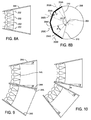
- Fig. 8A shows another horn type loudspeaker arrangement in which the horn is configured so the acoustic paths from each acoustic driver to the combined diffraction slot are of equal length and so that centerlines 202 of the ducts are normal to an arc 204.
- Arranging the ducts so that the centerlines 202 are in an arc permits the he top wall 20A (of previous figures) and the bottom wall 20B (of previous figures) of the horn to coincide with the top 24A and bottom 24B of the enclosure; for convenience, the top and bottom of the horn and the top and bottom of the enclosure will both be referred to by reference numbers 24A and 24B.
- the only significant gap in between the diffraction slots 14A and 14B is the thickness of the top wall of one horn loudspeaker and the bottom wall of the horn loudspeaker above.
- a typical thickness for the top wall and the bottom wall is 1.3 cm (0.5 inches) so that the gap is about 2.6 cm (1.0 inches).
- the walls of acoustic ducts are typically about 3 mm (0.12 inches) thick, so the gaps are about 6 mm (0.24 inches).
- Gaps of less than an 1 cm generally do not affect the radiation pattern by a significant amount, so diffraction slot or diffraction slot section with gaps of less than 1 cm will be considered substantially continuous.
- horn loudspeaker array configurations such as to form a "J" shaped horn array, with a continuous diffraction slot
- Fig. 9 an undesirable space between the horns and an undesirable gap in the diffraction slot will occur.
- Having horns with a variety of vertical dispersion angles permits the arrays to be formed without undesirable spaces between the horns and without undesirable gaps in the diffraction slot.
- the angle ⁇ of Fig. 9 could be as small as five degrees or even zero degrees (so that the horn is rectangular when viewed from the side) or as large as thirty degrees or larger.
- the top and bottom may be flared at the same angle, so that the combined flare of the enclosure top 24A and bottom 24B is 2 ⁇ degrees.
- top wall 20A (of previous figures) and the bottom wall 20B (of previous figures) of the horn are also the top 24A and bottom 24B of the enclosure, the combined flare of the top and bottom is the same as the vertical dispersion angle of the horn.
- Horns can be constructed so that any vertical dispersion can be provided, or the angle can be varied incrementally, for example in five or ten degree increments.
- Fig. 8B shows illustrates some features of the horn loudspeaker of Fig. 8A .
- Lines 204A - 204D represent the ducts of four acoustic modules arranged to form a single continuous diffraction slot.
- Each of the ducts has a centerline 202A - 202D, respectively.
- the centerlines are normal to an arc that is a portion of circle 206.
- the centerlines intersect at a point 208 at an angle ⁇ .
- Line 210 from intersection point 208 to one end of the diffraction slot and line 212 form the intersection point 208 to the other end of the diffraction slot intersect at angle VD, which is the vertical dispersion angle of the horn loudspeaker.
- Lines 204A - 204D also represent the planes of the openings of the outlet ends of the acoustic ducts. The planes intersect at an angle P. Rearranging the ducts to change the vertical dispersion angle also causes the angle P to change.
- a difficulty with horn loudspeakers according to Fig. 8 with large vertical dispersion angles is that if the acoustic driver and acoustic duct assemblies are arranged so that the exits of the acoustic ducts are normal to an arc, the acoustic drivers and/or the acoustic ducts may overlap vertically. In that case, the acoustic ducts and the acoustic drivers may be displaced horizontally, as shown in Fig. 11 . This allows the top and bottom walls 20A and 20B to coincide with the top and bottom walls 24A and 24B for larger vertical dispersion angles than are possible if the acoustic ducts and acoustic drivers are not displaced horizontally.
- the acoustic ducts may be curved, as shown in Fig. 12 .
- the curve may extend so far that one or more of the acoustic drivers may be partially or wholly forward of the throat 13. In addition to decreasing the depth of the overall assembly, this has the advantage of moving the acoustic drivers to a location where there is more vertical room for them, allowing the use of drivers with larger outer diameters.
- Fig. 13 shows a horn loudspeaker in which two acoustic drivers 12A and 12B are acoustically coupled to acoustic ducts 16A and 16B, respectively.
- acoustic ducts are merged at a position between the acoustic drivers and the throat 13, so that combined acoustic energy radiated by acoustic drivers 12A and 12B is radiated into the horn through the diffraction slot in about the same vertical space that the acoustic energy from one acoustic driver is radiated into the horn through the diffraction slot in configurations such as Fig. 1 .
- Fig. 14 shows a first modular assembly 120A including an acoustic driver 12A and acoustic duct 16A and a second modular assembly 120B including an acoustic driver 12B and acoustic duct 16B.
- Modules 120A and 120B are asymmetric about the Y-Axis.
- the acoustic ducts are curved as in Fig. 12 .
- the modular assembly 120B is substantially identical to the modular assembly 120A, but the second modular assembly 120B is rotated 180 degrees about the Y-axis relative to the orientation of modular assembly 120A.
- the opening at the outlet end of each of the ducts has a height of about 5.7 cm (2.25 inches) and a width of about 1.9 cm (0.75 inches).
- the modular assemblies 120A and 120B are positioned so that the outlet ends are aligned in the direction of elongation and held in that position by attaching them to a mounting plate, or "keel", most clearly seen in Figs. 16 , 20 , 21 , and 23 .
- Additional modular assemblies can be similarly aligned to form an acoustic assembly that can be acoustically coupled to the throat of a horn to form a horn loudspeaker.
- six modular assemblies are aligned in the manner shown in Fig. 14 , with the outlet ends arranged as in Fig. 8 .
- the six modular assemblies can be mechanically and acoustically coupled to the throat of an acoustic horn to form a horn loudspeaker.
- the combined outlet end openings operate as a diffraction slot for the acoustic horn.
- the outlet ends of the acoustic ducts 120A and 120B may have vertical flanges 68A and 68B to facilitate mating with the horn wall and may have horizontal flanges 66A and 66B to facilitate mating with other acoustic ducts to form a diffraction slot, as will be described below.
- a modular assembly such as modular assemblies 120A and 120B is advantageous because it enables providing horn loudspeakers with a wide range of horizontal and vertical dispersion angles with many of the parts being standard.
- the assemblies 120A and 120B including the acoustic driver 12A and 12B, respectively, and the acoustic duct 16A and 16B, respectively, are standard, as are the top wall 24A and the bottom wall 24B, and the bass modules 80A and 80B of Fig. 24 , including bass enclosures 82A and 82B (of Fig. 24 ) and woofer drivers 86 (of Fig. 24 ).
- Only side walls 18A and 18B, keel 56 (most clearly seen in Figs. 16 , 20 , 21 , and 23 ) and side bracket 57 (of Fig. 24 ) vary from horn to horn.
- Fig. 15 shows a modular assembly with mounting plates 112A and 112B, for two acoustic drivers (not shown in this view) in a configuration similar to the acoustic duct of Fig. 13 .
- Modular assemblies such as shown in Fig. 15 can be positioned in the same manner as modular assemblies 120A and 120B of Fig. 14 .
- Figs. 16 and 17 show a front view and a rear view, respectively, of an assembly of six acoustic drivers 12A - 12F and six acoustic ducts 16A - 16F.
- the outlets of the acoustic ducts 16A - 16F are aligned to form the diffraction slot 14.
- the acoustic ducts are positioned by, and held in place by, the keel 56.
- the keel 56 orients the outlets of the acoustic ducts normal to an arc and holds the acoustic modules in the desired position and orientation.
- Gaskets (not identified in this view) may be placed between the lower edge of one acoustic duct and the top edge of the acoustic duct below to prevent airflow leakage or airflow disturbances.
- Figs. 18A - 18E show side views of six modular assemblies 120A - 120F positioned to form an acoustic assembly 150 to mate with the throat of a horn to form a horn loudspeaker.
- Fig. 18A shows the orientation of the acoustic drivers and acoustic ducts assemblies with a vertical dispersion angle of five degrees; the curve of the arc is barely perceptible and there is moderate vertical overlap between the acoustic drivers 12A - 12F.
- Figs. 18B - 18E show the orientation of the acoustic driver and acoustic duct assemblies with vertical dispersion angles of 10 degrees, 20 degrees, 40 degrees, and 60 degrees, respectively. The curve of the arc becomes more pronounced and there is significant vertical overlap between the acoustic drivers 14A - 14F.
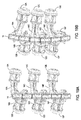
- Figs. 19A and 19B show front oblique isometric views of an acoustic assembly similar to the acoustic assemblies of Figs. 18A - 18E , with vertical dispersion angles of 5 degrees and 60 degrees, respectively.
- Figs. 19A and 19B show how the openings at the outlet end of the acoustic ducts are aligned to form an arcuate diffraction slot 14. In Fig. 19A , the arc is barely perceptible, while in Fig. 19B , the arc is more pronounced.
- Figs. 20 and 21 show a top view and an oblique back isometric view, respectively, of an acoustic driver and acoustic duct assembly according to Figs. 19A and 19B , with the horn side walls 18A and 18B.
- he horn side walls 18A and 18B are not planar and have some curvature, so a portion of the surface of the side walls is visible in the top view of Fig. 19A .
- the top and bottom walls are omitted from this view.
- the side walls 18A and 18B are shown as flaring symmetrically in the X-Y plane. In some implementations, the side walls may flare asymmetrically in the X-Y plane.
- Fig. 22 shows an assembly including twelve acoustic drivers.
- six acoustic drivers 12A - 12F are visible, a seventh acoustic driver 12G is partially obscured and the remaining five acoustic drivers are hidden in this view.
- the twelve acoustic drivers are arranged in six pairs. Each pair of acoustic drivers are acoustically coupled to an acoustic duct 16A - 16F according to Figs. 13 and 15 .
- a portion of each of the acoustic drivers (for example acoustic driver 12A) is forward of the diffraction slot which is positioned at the throat 13 of the horn.
- the horn of Fig. 22 is formed according to U.S. Pat. App. US Pat. App. 12/557,885 .
- a similar acoustic driver and acoustic duct arrangement can be implemented with a horn according to this specification.
- Fig. 23 shows an oblique isometric front view of the assembly of Figs. 20 and 21 with the top and bottom enclosure walls 24A and 24B (which, as described above in the discussion of Fig. 8 also are the top and bottom horn walls) angled to provide a 40 degree vertical dispersion angle.
- the curve of the front edge 70 of the keel 56 is visible.
- the top wall 24A and the bottom wall 24B may be mechanically fastened to the ends of keel 56.
- the enclosure 22 has no sides or back, and the same parts can be used for the top wall 24A and bottom wall 24B regardless of the vertical dispersion angle.
- the horn side walls 18A and 18B may be held in place by mechanical fastening to the keel 56 and by inserting the top and bottom edges of the side walls into slots 74 in the top and bottom 24A and 24B.
- Fig. 24 shows the assembly of Fig. 23 with bass modules 80A and 80B.
- Bass modules 80A and 80B may includes a 25.4 cm (10 inch) nominal woofer driver 86 mounted in a bass enclosure 82 with a port 84.
- the bass modules may be mechanically fastened to a side bracket 57 which may be mechanically fastened to the top wall 24A and bottom wall 24B.
- the assembly of Fig. 23 enables providing horn loudspeakers with a wide range of vertical dispersion angle and horizontal dispersion angles with many parts that are standard for all vertical and horizontal dispersion angles and with a minimum of variation in the manufacturing process.
- the top wall 24A, the bottom wall 24B, the acoustic drivers, acoustic ducts and the bass module may all be standard. Only the keel 56, the side bracket 57, and the horn side walls 18A and 18B need to be varied to vary the vertical dispersion angle.
- the horizontal dispersion angle can be varied by varying the orientation of the slots 74.
- the assembly process for all horn loudspeakers, regardless of vertical or horizontal dispersion angle, is substantially identical.
Landscapes
- Health & Medical Sciences (AREA)
- Otolaryngology (AREA)
- Physics & Mathematics (AREA)
- Engineering & Computer Science (AREA)
- Acoustics & Sound (AREA)
- Signal Processing (AREA)
- Multimedia (AREA)
- Obtaining Desirable Characteristics In Audible-Bandwidth Transducers (AREA)
- Details Of Audible-Bandwidth Transducers (AREA)
Claims (6)
- Verfahren zum Bilden von Lautsprechergruppen, das Folgendes umfasst:Bereitstellen von mindestens zwei Schalltrichtern aus einer ersten Mehrzahl von Schalltrichtern, wobei jede der Mehrzahl von Schalltrichtern einen unterschiedlichen vertikalen Abstrahlwinkel hat, Seitenwände (18A, 18B) und eine Oberseite, die eine flache Oberfläche (24A) hat, und einen Boden, der eine flache Bodenfläche (24B) ungeachtet des jeweiligen Abstrahlwinkels hat, wobei die Oberseite und der Boden eine Stärke haben und an Enden eines Kiels (56) befestigt sind, an dem modulare Anordnungen (120A, 120B), die einen akustischen Treiber (12A, 12B) und einen akustischen Kanal (16A, 16B) aufweisen, befestigt sind, und wobei jeder Schalltrichter einen Brechungsschlitz umfasst,Bereitstellen von Schlitzen (74) in der Oberseite und dem Boden jedes Schalltrichters, wobei die Ausrichtung der Schlitze variiert wird, um den horizontalen Abstrahlwinkel des Schalltrichters zu variieren, und Platzieren der Seitenwände in dem Schalltrichter durch Befestigen der Seitenwände an dem Kiel und durch Einfügen oberer und unterer Kanten der Seitenwände in die Schlitze,Einrichten der Mehrzahl von Schalltrichtern derart, dass die Oberfläche eines Schalltrichters parallel zu und in flachem Kontakt mit der Bodenfläche eines benachbarten Schalltrichters ist, und derart, dass die Schalltrichter-Brechungsschlitze ausgerichtet sind, um eine Brechungsschlitzgruppe mit Spalten zu bilden, die nicht wesentlich größer sind als die kombinierte Stärke der Oberseite des einen Schalltrichters und des Bodens des anderen benachbarten Schalltrichters.
- Verfahren nach Anspruch 1, wobei das Bereitstellen
das Bilden eines ersten der Schalltrichter aus einer Mehrzahl aus im Wesentlichen identischen Schallmodulen umfasst, wobei jedes Modul einen akustischen Treiber und einen akustischen Kanal umfasst, der eine Öffnung hat, wobei jeder akustische Kanal durch eine Mittenlinie gekennzeichnet ist,
wobei das Bilden das Einrichten der ersten Mehrzahl akustischer Module derart umfasst, dass die Mittenlinien zu einem ersten Bogen senkrecht sind und an einem Winkel schneiden, und derart, dass die Öffnungen ausgerichtet sind, um den ersten Schalltrichter-Brechungsschlitz zu bilden; und
Bilden eines zweiten der Schalltrichter aus einer zweiten Mehrzahl akustischer Module, die im Wesentlichen mit der ersten Mehrzahl akustischer Module identisch ist, wobei jedes Modul einen akustischen Treiber und einen akustischen Kanal umfasst, der eine Öffnung hat, wobei jeder akustische Kanal durch eine Mittenlinie gekennzeichnet ist,
wobei das Bilden das Einrichten der zweiten Mehrzahl akustischer Module derart umfasst, dass die Mittenlinie zu einem zweiten Bogen senkrecht sind, und derart, dass die Öffnungen ausgerichtet sind, um den zweiten Schalltrichter-Brechungsschlitz zu bilden. - Verfahren nach Anspruch 2, wobei das Bilden des ersten der akustischen Schalltrichter ferner das Einrichten der ersten Mehrzahl akustischer Module derart umfasst, dass sich die Mittenlinien an einer ersten Mehrzahl von Winkeln schneiden.
- Verfahren nach Anspruch 3, wobei das Bilden des zweiten der akustischen Schalltrichter das Einrichten der zweiten Mehrzahl akustischer Module derart umfasst, dass die Mittenlinien sich an einem zweiten der Mehrzahl von Winkeln, der von dem ersten der Mehrzahl von Winkeln unterschiedlich ist, schneiden.
- Verfahren nach Anspruch 2, wobei die erste Mehrzahl akustischer Module und die zweite Mehrzahl akustischer Module im Wesentlichen identisch sind.
- Verfahren nach Anspruch 2, wobei akustische Module der ersten und/oder zweiten Mehrzahl um mindestens eine Achse asymmetrisch und um 180° um die Achse in Bezug zueinander gedreht sind.
Applications Claiming Priority (2)
| Application Number | Priority Date | Filing Date | Title |
|---|---|---|---|
| US12/898,947 US9111521B2 (en) | 2009-09-11 | 2010-10-06 | Modular acoustic horns and horn arrays |
| PCT/US2011/053635 WO2012047694A1 (en) | 2010-10-06 | 2011-09-28 | Modular acoustic horns and horn arrays |
Publications (2)
| Publication Number | Publication Date |
|---|---|
| EP2625870A1 EP2625870A1 (de) | 2013-08-14 |
| EP2625870B1 true EP2625870B1 (de) | 2016-05-18 |
Family
ID=44801177
Family Applications (1)
| Application Number | Title | Priority Date | Filing Date |
|---|---|---|---|
| EP11770257.1A Active EP2625870B1 (de) | 2010-10-06 | 2011-09-28 | Modularer hornlautsprecher und gruppe von hornlautsprechern |
Country Status (5)
| Country | Link |
|---|---|
| US (3) | US9111521B2 (de) |
| EP (1) | EP2625870B1 (de) |
| JP (1) | JP2013542463A (de) |
| CN (1) | CN103262569B (de) |
| WO (1) | WO2012047694A1 (de) |
Families Citing this family (35)
| Publication number | Priority date | Publication date | Assignee | Title |
|---|---|---|---|---|
| US10110993B1 (en) * | 2015-12-02 | 2018-10-23 | Ati Systems, Inc. | High-power electronic omnidirectional speaker array |
| KR101166794B1 (ko) | 2011-07-08 | 2012-07-31 | 주식회사 도담시스템스 | 압축드라이버 다중 입력 방식의 고출력 지향성 라우드 스피커 |
| GB2493922A (en) * | 2011-08-19 | 2013-02-27 | Flare Audio Holdings Ltd | Symmetric multi-horn loudspeaker system |
| US9219954B2 (en) * | 2013-03-15 | 2015-12-22 | Loud Technologies Inc | Acoustic horn manifold |
| US9911406B2 (en) | 2013-03-15 | 2018-03-06 | Loud Audio, Llc | Method and system for large scale audio system |
| USRE49437E1 (en) | 2014-09-30 | 2023-02-28 | Apple Inc. | Audio driver and power supply unit architecture |
| CN115550821A (zh) | 2014-09-30 | 2022-12-30 | 苹果公司 | 具有减小的由来自表面的反射导致的音频染色的扬声器 |
| US9769560B2 (en) * | 2015-06-09 | 2017-09-19 | Harman International Industries, Incorporated | Manifold for multiple compression drivers with a single point source exit |
| US10547934B2 (en) * | 2015-11-24 | 2020-01-28 | Lloyd Baggs Innovations, Llc | Speaker assemblies with wide dispersion patterns |
| US9716942B2 (en) * | 2015-12-22 | 2017-07-25 | Bose Corporation | Mitigating effects of cavity resonance in speakers |
| US9712911B2 (en) * | 2015-12-22 | 2017-07-18 | Bose Corporation | Conformable adaptors for diffraction slots in speakers |
| US10602263B2 (en) | 2016-02-24 | 2020-03-24 | Dolby Laboratories Licensing Corporation | Planar loudspeaker manifold for improved sound dispersion |
| US9860633B2 (en) * | 2016-06-03 | 2018-01-02 | Harman International Industries, Incorporated | Baffle for line array loudspeaker |
| ITUA20164154A1 (it) * | 2016-06-07 | 2017-12-07 | Zingali Loudspeaker Srl | Diffusore acustico e procedimento di realizzazione dello stesso |
| ITUA20164157A1 (it) * | 2016-06-07 | 2017-12-07 | Zingali Loudspeaker Srl | Diffusore acustico |
| CN106098055A (zh) * | 2016-08-11 | 2016-11-09 | 广州励丰文化科技股份有限公司 | 一种波导管装置 |
| KR101840939B1 (ko) * | 2016-08-30 | 2018-05-04 | 박상일 | 고성능 확성기를 이용한 기동형 대형 확성장치 |
| US10631071B2 (en) | 2016-09-23 | 2020-04-21 | Apple Inc. | Cantilevered foot for electronic device |
| US10257608B2 (en) | 2016-09-23 | 2019-04-09 | Apple Inc. | Subwoofer with multi-lobe magnet |
| USD886764S1 (en) | 2016-11-09 | 2020-06-09 | Lloyd Baggs Innovations, Llc | Speaker |
| CN106597450B (zh) * | 2016-12-09 | 2019-07-30 | 中国科学院电子学研究所 | 一种声探测与定位系统 |
| CN107071663B (zh) * | 2017-04-26 | 2022-09-06 | 大连理工大学 | 宽带超薄声波扩散结构 |
| WO2019140011A1 (en) | 2018-01-09 | 2019-07-18 | Qsc, Llc | Multi-way acoustic waveguide for a speaker assembly |
| US10225648B1 (en) | 2018-01-17 | 2019-03-05 | Harman International Industries, Incorporated | Horn array |
| US10587951B1 (en) * | 2018-09-13 | 2020-03-10 | Plantronics, Inc. | Equipment including down-firing speaker |
| CN109547900B (zh) * | 2018-11-22 | 2020-10-30 | 斯贝克电子(嘉善)有限公司 | 一种号角 |
| CN109462784B (zh) * | 2018-12-06 | 2023-09-08 | 宁波东源音响器材有限公司 | 一种带压缩设计的阵列音箱 |
| US11558691B2 (en) | 2019-02-22 | 2023-01-17 | MTD Designs L.L.C. | Loudspeaker array cabinet |
| US11206504B2 (en) | 2019-04-02 | 2021-12-21 | Syng, Inc. | Systems and methods for spatial audio rendering |
| GB2583075A (en) * | 2019-04-02 | 2020-10-21 | Em Acoustics Ltd | Manifold for a loudspeaker |
| WO2021195342A1 (en) | 2020-03-25 | 2021-09-30 | Qsc, Llc | Acoustic waveguide |
| JP7635267B2 (ja) * | 2020-06-10 | 2025-02-25 | ドルビー ラボラトリーズ ライセンシング コーポレイション | 非対称音響ホーン |
| US11681044B2 (en) * | 2021-06-21 | 2023-06-20 | Navico, Inc. | Sonar beam shape controlling horn |
| EP4434031A4 (de) | 2021-11-15 | 2025-10-15 | Syng Inc | Systeme und verfahren zur darstellung von räumlichem audio unter verwendung von verräumlichtungsshadern |
| CN117202013B (zh) * | 2023-08-18 | 2026-02-27 | 广州市有米声学科技有限公司 | 一种双声源波前不共腔水平耦合高音波导 |
Family Cites Families (64)
| Publication number | Priority date | Publication date | Assignee | Title |
|---|---|---|---|---|
| US2089391A (en) * | 1936-06-12 | 1937-08-10 | Electrical Res Prod Inc | Sound reproducing apparatus |
| US3234559A (en) * | 1960-05-07 | 1966-02-08 | Telefunken Patent | Multiple horn feed for parabolic reflector with phase and power adjustments |
| JPS4869325U (de) | 1971-12-07 | 1973-09-03 | ||
| US3977006A (en) * | 1975-05-12 | 1976-08-24 | Cutler-Hammer, Inc. | Compensated traveling wave slotted waveguide feed for cophasal arrays |
| US4171734A (en) * | 1977-11-10 | 1979-10-23 | Beta Sound, Incorporated | Exponential horn speaker |
| US4308932A (en) * | 1980-05-06 | 1982-01-05 | James B. Lansing Sound, Inc. ("Jbl") | Loudspeaker horn |
| US4344504A (en) * | 1981-03-27 | 1982-08-17 | Community Light & Sound, Inc. | Directional loudspeaker |
| US4580655A (en) | 1983-10-05 | 1986-04-08 | Jbl Incorporated | Defined coverage loudspeaker horn |
| US4629029A (en) * | 1985-11-15 | 1986-12-16 | Electro-Voice, Inc. | Multiple driver manifold |
| US4882562A (en) * | 1986-03-11 | 1989-11-21 | Turbosound Limited | Adaptor for coupling plural compression drivers to a common horn |
| US4845759A (en) * | 1986-04-25 | 1989-07-04 | Intersonics Incorporated | Sound source having a plurality of drivers operating from a virtual point |
| JP2945983B2 (ja) * | 1987-03-25 | 1999-09-06 | 久次 中村 | スピーカ装置 |
| US5020630A (en) | 1989-12-08 | 1991-06-04 | Electro-Voice, Inc. | Loudspeaker and horn therefor |
| JP3148954B2 (ja) | 1992-08-25 | 2001-03-26 | ティーオーエー株式会社 | スロート具 |
| WO1994019915A1 (en) * | 1993-02-25 | 1994-09-01 | Heinz Ralph D | Multiple-driver single horn loudspeaker |
| US5325439A (en) * | 1993-10-13 | 1994-06-28 | Smiley Jack R | Loudspeaker apparatus |
| JPH07143588A (ja) * | 1993-11-12 | 1995-06-02 | Hisaji Nakamura | 垂直アレイ型スピーカ装置 |
| JP3792285B2 (ja) | 1995-11-14 | 2006-07-05 | 松下電器産業株式会社 | スピーカ用ホーン |
| US6744899B1 (en) * | 1996-05-28 | 2004-06-01 | Robert M. Grunberg | Direct coupling of waveguide to compression driver having matching slot shaped throats |
| US5925856A (en) * | 1996-06-17 | 1999-07-20 | Meyer Sound Laboratories Incorporated | Loudspeaker horn |
| US5750943A (en) * | 1996-10-02 | 1998-05-12 | Renkus-Heinz, Inc. | Speaker array with improved phase characteristics |
| GB2325603B (en) | 1997-05-24 | 2001-08-22 | Celestion Internat Ltd | Acoustic horns for loudspeakers |
| US6016353A (en) | 1997-08-29 | 2000-01-18 | Eastern Acoustic Works, Inc. | Large scale sound reproduction system having cross-cabinet horizontal array of horn elements |
| US6009182A (en) * | 1997-08-29 | 1999-12-28 | Eastern Acoustic Works, Inc. | Down-fill speaker for large scale sound reproduction system |
| US6059069A (en) * | 1999-03-05 | 2000-05-09 | Peavey Electronics Corporation | Loudspeaker waveguide design |
| US6112847A (en) * | 1999-03-15 | 2000-09-05 | Clair Brothers Audio Enterprises, Inc. | Loudspeaker with differentiated energy distribution in vertical and horizontal planes |
| US6394223B1 (en) * | 1999-03-12 | 2002-05-28 | Clair Brothers Audio Enterprises, Inc. | Loudspeaker with differential energy distribution in vertical and horizontal planes |
| US6343133B1 (en) * | 1999-07-22 | 2002-01-29 | Alan Brock Adamson | Axially propagating mid and high frequency loudspeaker systems |
| US20010040974A1 (en) * | 2000-01-13 | 2001-11-15 | Steckling Jerome D. | Horn mode tuning |
| EP1358780A2 (de) * | 2000-05-30 | 2003-11-05 | Mark S. Ureda | Cross-fired multi-horn lautsprecherssystem |
| US6393131B1 (en) * | 2000-06-16 | 2002-05-21 | Scott Michael Rexroat | Loudspeaker |
| US6581719B2 (en) * | 2000-08-02 | 2003-06-24 | Alan Brock Adamson | Wave shaping sound chamber |
| FR2813986B1 (fr) | 2000-09-08 | 2002-11-29 | Eric Vincenot | Dispositif de sonorisation a guide d'onde acoustique |
| AU2000276332B2 (en) | 2000-09-22 | 2005-03-10 | Robert Grunberg | Direct coupling of waveguide to compression driver having matching slot shaped throats |
| WO2002056293A1 (en) * | 2001-01-11 | 2002-07-18 | Meyer Sound Laboratories Incorporated | Manifold for a horn loudspeaker |
| US7236606B2 (en) * | 2001-03-07 | 2007-06-26 | Harman International Industries, Incorporated | Sound system having a HF horn coaxially aligned in the mouth of a midrange horn |
| ITBS20010073A1 (it) | 2001-10-03 | 2003-04-03 | Outline Di Noselli G & C S N C | Altoparlante a guida d'onda a dispersione controllata e regolabile |
| US7177437B1 (en) * | 2001-10-19 | 2007-02-13 | Duckworth Holding, Llc C/O Osc Audio Products, Inc. | Multiple aperture diffraction device |
| US7936892B2 (en) | 2002-01-14 | 2011-05-03 | Harman International Industries, Incorporated | Constant coverage waveguide |
| GB0202284D0 (en) * | 2002-01-31 | 2002-03-20 | Martin Audio Ltd | Directional loudspeaker |
| US7392880B2 (en) * | 2002-04-02 | 2008-07-01 | Gibson Guitar Corp. | Dual range horn with acoustic crossover |
| US7278513B2 (en) | 2002-04-05 | 2007-10-09 | Harman International Industries, Incorporated | Internal lens system for loudspeaker waveguides |
| ITBS20020063A1 (it) * | 2002-07-09 | 2004-01-09 | Outline Di Noselli G & S N C | Guida d'onda a singola e multipla riflessione |
| JP2004064507A (ja) | 2002-07-30 | 2004-02-26 | Matsushita Electric Ind Co Ltd | スピーカ装置及びスピーカシステム |
| AU2002951421A0 (en) * | 2002-09-17 | 2002-10-03 | Krix Loudspeakers Pty Ltd | Constant directivity acoustic horn |
| US7299893B2 (en) * | 2003-02-21 | 2007-11-27 | Meyer Sound Laboratories, Incorporated | Loudspeaker horn and method for controlling grating lobes in a line array of acoustic sources |
| GB0306415D0 (en) * | 2003-03-20 | 2003-04-23 | Andrews Anthony J | Loudspeaker array |
| US7590257B1 (en) * | 2004-12-22 | 2009-09-15 | Klipsch, Llc | Axially propagating horn array for a loudspeaker |
| US7275621B1 (en) * | 2005-01-18 | 2007-10-02 | Klipsch, Llc | Skew horn for a loudspeaker |
| ITBS20050006A1 (it) * | 2005-01-28 | 2006-07-29 | Outline Di Noselli G & C S N C | Elemento diffusore del suono per formare sistemi di diffusori in linea verticale a direttivita' regolabile sia orizzontalmente sia verticalmente |
| NO322654B1 (no) | 2005-02-21 | 2006-11-13 | Rune Skramstad | Hoyttaler |
| GB2423908B (en) | 2005-03-02 | 2008-04-02 | Kh Technology Corp | Loudspeaker |
| DE202005020757U1 (de) | 2005-09-28 | 2006-07-20 | Pintsch Bamag Antriebs- Und Verkehrstechnik Gmbh | Lautsprecher |
| US20080085026A1 (en) * | 2005-10-05 | 2008-04-10 | Qsc Audio Products, Inc. | Curved line array with horizontal coverage control |
| US7835537B2 (en) * | 2005-10-13 | 2010-11-16 | Cheney Brian E | Loudspeaker including slotted waveguide for enhanced directivity and associated methods |
| GB2432289A (en) | 2005-11-09 | 2007-05-16 | Martin Audio Ltd | Horn for a curved line array of loudspeakers |
| US7708112B2 (en) * | 2005-11-10 | 2010-05-04 | Earl Russell Geddes | Waveguide phase plug |
| JP4396646B2 (ja) | 2006-02-07 | 2010-01-13 | ヤマハ株式会社 | 応答波形合成方法、応答波形合成装置、音響設計支援装置および音響設計支援プログラム |
| US8081766B2 (en) * | 2006-03-06 | 2011-12-20 | Loud Technologies Inc. | Creating digital signal processing (DSP) filters to improve loudspeaker transient response |
| US20080059132A1 (en) * | 2006-09-04 | 2008-03-06 | Krix Loudspeakers Pty Ltd | Method of designing a sound waveguide surface |
| WO2008112175A1 (en) | 2007-03-09 | 2008-09-18 | One Systems Group Co., Ltd | Compression driver and horn structure |
| JP2009065609A (ja) | 2007-09-10 | 2009-03-26 | Panasonic Corp | スピーカ装置 |
| CN201290172Y (zh) | 2008-09-26 | 2009-08-12 | 国光电器股份有限公司 | 扬声器用音盆、使用该音盆的扬声器、使用该扬声器的电子产品 |
| US8917896B2 (en) | 2009-09-11 | 2014-12-23 | Bose Corporation | Automated customization of loudspeakers |
-
2010
- 2010-10-06 US US12/898,947 patent/US9111521B2/en active Active
-
2011
- 2011-09-28 JP JP2013532835A patent/JP2013542463A/ja active Pending
- 2011-09-28 CN CN201180048401.9A patent/CN103262569B/zh active Active
- 2011-09-28 WO PCT/US2011/053635 patent/WO2012047694A1/en not_active Ceased
- 2011-09-28 EP EP11770257.1A patent/EP2625870B1/de active Active
-
2014
- 2014-12-10 US US14/565,843 patent/US20150090521A1/en not_active Abandoned
-
2016
- 2016-09-02 US US15/255,358 patent/US9894432B2/en active Active
Non-Patent Citations (1)
| Title |
|---|
| None * |
Also Published As
| Publication number | Publication date |
|---|---|
| CN103262569A (zh) | 2013-08-21 |
| WO2012047694A1 (en) | 2012-04-12 |
| US9894432B2 (en) | 2018-02-13 |
| US20150090521A1 (en) | 2015-04-02 |
| CN103262569B (zh) | 2016-11-09 |
| EP2625870A1 (de) | 2013-08-14 |
| JP2013542463A (ja) | 2013-11-21 |
| US20160373856A1 (en) | 2016-12-22 |
| US20110069856A1 (en) | 2011-03-24 |
| US9111521B2 (en) | 2015-08-18 |
Similar Documents
| Publication | Publication Date | Title |
|---|---|---|
| EP2625870B1 (de) | Modularer hornlautsprecher und gruppe von hornlautsprechern | |
| JP2013542463A6 (ja) | モジュール式ホーンおよびホーンアレイ | |
| EP2676457B1 (de) | Verwaltung der verstärkung einer hupe | |
| US10721554B2 (en) | Audio directing loudspeaker grill | |
| EP3646616B1 (de) | Elektroakustischer wandler eines soundsystems | |
| EP1460880A2 (de) | Lautsprechersanordnung | |
| EP2293596B1 (de) | Multidirektionales Tonausgabesystem | |
| WO2016044616A1 (en) | Loudspeaker with narrow dispersion | |
| US7299893B2 (en) | Loudspeaker horn and method for controlling grating lobes in a line array of acoustic sources | |
| EP2974363B1 (de) | Verteiler für eine akustische hupe | |
| EP1941780B1 (de) | Elektroakustische line-array-wandlung | |
| EP3427489B1 (de) | Lautsprechermodule mit verschiedenen modulgehäusegeometrien und ähnlichen akustischen eigenschaften | |
| US8027493B2 (en) | Biplane line array speaker with arcuate tweeter array providing controlled directivity | |
| EP3420738B1 (de) | Planarlautsprecherverteiler für verbesserte schalldispersion | |
| EP3515091B1 (de) | Lautsprecher-hornarray | |
| HK1186035A (en) | Modular acoustic horns and horn arrays | |
| EP2724553B1 (de) | Hupengehäuse zum kombinieren von tonausgaben | |
| HK1121330B (en) | Line array electroacoustical transducing | |
| HK40017054A (en) | Electro-acoustical transducer arrangements of a sound system |
Legal Events
| Date | Code | Title | Description |
|---|---|---|---|
| PUAI | Public reference made under article 153(3) epc to a published international application that has entered the european phase |
Free format text: ORIGINAL CODE: 0009012 |
|
| 17P | Request for examination filed |
Effective date: 20130402 |
|
| AK | Designated contracting states |
Kind code of ref document: A1 Designated state(s): AL AT BE BG CH CY CZ DE DK EE ES FI FR GB GR HR HU IE IS IT LI LT LU LV MC MK MT NL NO PL PT RO RS SE SI SK SM TR |
|
| DAX | Request for extension of the european patent (deleted) | ||
| 17Q | First examination report despatched |
Effective date: 20141008 |
|
| GRAP | Despatch of communication of intention to grant a patent |
Free format text: ORIGINAL CODE: EPIDOSNIGR1 |
|
| INTG | Intention to grant announced |
Effective date: 20160302 |
|
| GRAS | Grant fee paid |
Free format text: ORIGINAL CODE: EPIDOSNIGR3 |
|
| GRAA | (expected) grant |
Free format text: ORIGINAL CODE: 0009210 |
|
| AK | Designated contracting states |
Kind code of ref document: B1 Designated state(s): AL AT BE BG CH CY CZ DE DK EE ES FI FR GB GR HR HU IE IS IT LI LT LU LV MC MK MT NL NO PL PT RO RS SE SI SK SM TR |
|
| REG | Reference to a national code |
Ref country code: GB Ref legal event code: FG4D |
|
| REG | Reference to a national code |
Ref country code: CH Ref legal event code: EP |
|
| REG | Reference to a national code |
Ref country code: IE Ref legal event code: FG4D Ref country code: AT Ref legal event code: REF Ref document number: 801337 Country of ref document: AT Kind code of ref document: T Effective date: 20160615 |
|
| REG | Reference to a national code |
Ref country code: DE Ref legal event code: R096 Ref document number: 602011026741 Country of ref document: DE |
|
| REG | Reference to a national code |
Ref country code: NL Ref legal event code: MP Effective date: 20160518 |
|
| REG | Reference to a national code |
Ref country code: LT Ref legal event code: MG4D Ref country code: FR Ref legal event code: PLFP Year of fee payment: 6 |
|
| PG25 | Lapsed in a contracting state [announced via postgrant information from national office to epo] |
Ref country code: NL Free format text: LAPSE BECAUSE OF FAILURE TO SUBMIT A TRANSLATION OF THE DESCRIPTION OR TO PAY THE FEE WITHIN THE PRESCRIBED TIME-LIMIT Effective date: 20160518 Ref country code: NO Free format text: LAPSE BECAUSE OF FAILURE TO SUBMIT A TRANSLATION OF THE DESCRIPTION OR TO PAY THE FEE WITHIN THE PRESCRIBED TIME-LIMIT Effective date: 20160818 Ref country code: LT Free format text: LAPSE BECAUSE OF FAILURE TO SUBMIT A TRANSLATION OF THE DESCRIPTION OR TO PAY THE FEE WITHIN THE PRESCRIBED TIME-LIMIT Effective date: 20160518 Ref country code: FI Free format text: LAPSE BECAUSE OF FAILURE TO SUBMIT A TRANSLATION OF THE DESCRIPTION OR TO PAY THE FEE WITHIN THE PRESCRIBED TIME-LIMIT Effective date: 20160518 |
|
| REG | Reference to a national code |
Ref country code: AT Ref legal event code: MK05 Ref document number: 801337 Country of ref document: AT Kind code of ref document: T Effective date: 20160518 |
|
| PG25 | Lapsed in a contracting state [announced via postgrant information from national office to epo] |
Ref country code: HR Free format text: LAPSE BECAUSE OF FAILURE TO SUBMIT A TRANSLATION OF THE DESCRIPTION OR TO PAY THE FEE WITHIN THE PRESCRIBED TIME-LIMIT Effective date: 20160518 Ref country code: LV Free format text: LAPSE BECAUSE OF FAILURE TO SUBMIT A TRANSLATION OF THE DESCRIPTION OR TO PAY THE FEE WITHIN THE PRESCRIBED TIME-LIMIT Effective date: 20160518 Ref country code: GR Free format text: LAPSE BECAUSE OF FAILURE TO SUBMIT A TRANSLATION OF THE DESCRIPTION OR TO PAY THE FEE WITHIN THE PRESCRIBED TIME-LIMIT Effective date: 20160819 Ref country code: SE Free format text: LAPSE BECAUSE OF FAILURE TO SUBMIT A TRANSLATION OF THE DESCRIPTION OR TO PAY THE FEE WITHIN THE PRESCRIBED TIME-LIMIT Effective date: 20160518 Ref country code: RS Free format text: LAPSE BECAUSE OF FAILURE TO SUBMIT A TRANSLATION OF THE DESCRIPTION OR TO PAY THE FEE WITHIN THE PRESCRIBED TIME-LIMIT Effective date: 20160518 Ref country code: PT Free format text: LAPSE BECAUSE OF FAILURE TO SUBMIT A TRANSLATION OF THE DESCRIPTION OR TO PAY THE FEE WITHIN THE PRESCRIBED TIME-LIMIT Effective date: 20160919 Ref country code: ES Free format text: LAPSE BECAUSE OF FAILURE TO SUBMIT A TRANSLATION OF THE DESCRIPTION OR TO PAY THE FEE WITHIN THE PRESCRIBED TIME-LIMIT Effective date: 20160518 |
|
| PG25 | Lapsed in a contracting state [announced via postgrant information from national office to epo] |
Ref country code: IT Free format text: LAPSE BECAUSE OF FAILURE TO SUBMIT A TRANSLATION OF THE DESCRIPTION OR TO PAY THE FEE WITHIN THE PRESCRIBED TIME-LIMIT Effective date: 20160518 |
|
| PG25 | Lapsed in a contracting state [announced via postgrant information from national office to epo] |
Ref country code: EE Free format text: LAPSE BECAUSE OF FAILURE TO SUBMIT A TRANSLATION OF THE DESCRIPTION OR TO PAY THE FEE WITHIN THE PRESCRIBED TIME-LIMIT Effective date: 20160518 Ref country code: CZ Free format text: LAPSE BECAUSE OF FAILURE TO SUBMIT A TRANSLATION OF THE DESCRIPTION OR TO PAY THE FEE WITHIN THE PRESCRIBED TIME-LIMIT Effective date: 20160518 Ref country code: RO Free format text: LAPSE BECAUSE OF FAILURE TO SUBMIT A TRANSLATION OF THE DESCRIPTION OR TO PAY THE FEE WITHIN THE PRESCRIBED TIME-LIMIT Effective date: 20160518 Ref country code: DK Free format text: LAPSE BECAUSE OF FAILURE TO SUBMIT A TRANSLATION OF THE DESCRIPTION OR TO PAY THE FEE WITHIN THE PRESCRIBED TIME-LIMIT Effective date: 20160518 Ref country code: SK Free format text: LAPSE BECAUSE OF FAILURE TO SUBMIT A TRANSLATION OF THE DESCRIPTION OR TO PAY THE FEE WITHIN THE PRESCRIBED TIME-LIMIT Effective date: 20160518 |
|
| REG | Reference to a national code |
Ref country code: DE Ref legal event code: R097 Ref document number: 602011026741 Country of ref document: DE |
|
| PG25 | Lapsed in a contracting state [announced via postgrant information from national office to epo] |
Ref country code: BE Free format text: LAPSE BECAUSE OF NON-PAYMENT OF DUE FEES Effective date: 20160518 Ref country code: PL Free format text: LAPSE BECAUSE OF FAILURE TO SUBMIT A TRANSLATION OF THE DESCRIPTION OR TO PAY THE FEE WITHIN THE PRESCRIBED TIME-LIMIT Effective date: 20160518 Ref country code: SM Free format text: LAPSE BECAUSE OF FAILURE TO SUBMIT A TRANSLATION OF THE DESCRIPTION OR TO PAY THE FEE WITHIN THE PRESCRIBED TIME-LIMIT Effective date: 20160518 Ref country code: AT Free format text: LAPSE BECAUSE OF FAILURE TO SUBMIT A TRANSLATION OF THE DESCRIPTION OR TO PAY THE FEE WITHIN THE PRESCRIBED TIME-LIMIT Effective date: 20160518 |
|
| PLBE | No opposition filed within time limit |
Free format text: ORIGINAL CODE: 0009261 |
|
| STAA | Information on the status of an ep patent application or granted ep patent |
Free format text: STATUS: NO OPPOSITION FILED WITHIN TIME LIMIT |
|
| 26N | No opposition filed |
Effective date: 20170221 |
|
| PG25 | Lapsed in a contracting state [announced via postgrant information from national office to epo] |
Ref country code: MC Free format text: LAPSE BECAUSE OF FAILURE TO SUBMIT A TRANSLATION OF THE DESCRIPTION OR TO PAY THE FEE WITHIN THE PRESCRIBED TIME-LIMIT Effective date: 20160518 |
|
| REG | Reference to a national code |
Ref country code: CH Ref legal event code: PL |
|
| PG25 | Lapsed in a contracting state [announced via postgrant information from national office to epo] |
Ref country code: SI Free format text: LAPSE BECAUSE OF FAILURE TO SUBMIT A TRANSLATION OF THE DESCRIPTION OR TO PAY THE FEE WITHIN THE PRESCRIBED TIME-LIMIT Effective date: 20160518 |
|
| REG | Reference to a national code |
Ref country code: IE Ref legal event code: MM4A |
|
| PG25 | Lapsed in a contracting state [announced via postgrant information from national office to epo] |
Ref country code: LI Free format text: LAPSE BECAUSE OF NON-PAYMENT OF DUE FEES Effective date: 20160930 Ref country code: CH Free format text: LAPSE BECAUSE OF NON-PAYMENT OF DUE FEES Effective date: 20160930 Ref country code: IE Free format text: LAPSE BECAUSE OF NON-PAYMENT OF DUE FEES Effective date: 20160928 |
|
| PG25 | Lapsed in a contracting state [announced via postgrant information from national office to epo] |
Ref country code: LU Free format text: LAPSE BECAUSE OF NON-PAYMENT OF DUE FEES Effective date: 20160928 |
|
| REG | Reference to a national code |
Ref country code: FR Ref legal event code: PLFP Year of fee payment: 7 |
|
| PG25 | Lapsed in a contracting state [announced via postgrant information from national office to epo] |
Ref country code: HU Free format text: LAPSE BECAUSE OF FAILURE TO SUBMIT A TRANSLATION OF THE DESCRIPTION OR TO PAY THE FEE WITHIN THE PRESCRIBED TIME-LIMIT; INVALID AB INITIO Effective date: 20110928 Ref country code: CY Free format text: LAPSE BECAUSE OF FAILURE TO SUBMIT A TRANSLATION OF THE DESCRIPTION OR TO PAY THE FEE WITHIN THE PRESCRIBED TIME-LIMIT Effective date: 20160518 |
|
| PG25 | Lapsed in a contracting state [announced via postgrant information from national office to epo] |
Ref country code: MT Free format text: LAPSE BECAUSE OF NON-PAYMENT OF DUE FEES Effective date: 20160930 Ref country code: IS Free format text: LAPSE BECAUSE OF FAILURE TO SUBMIT A TRANSLATION OF THE DESCRIPTION OR TO PAY THE FEE WITHIN THE PRESCRIBED TIME-LIMIT Effective date: 20160518 Ref country code: TR Free format text: LAPSE BECAUSE OF FAILURE TO SUBMIT A TRANSLATION OF THE DESCRIPTION OR TO PAY THE FEE WITHIN THE PRESCRIBED TIME-LIMIT Effective date: 20160518 Ref country code: MK Free format text: LAPSE BECAUSE OF FAILURE TO SUBMIT A TRANSLATION OF THE DESCRIPTION OR TO PAY THE FEE WITHIN THE PRESCRIBED TIME-LIMIT Effective date: 20160518 |
|
| PG25 | Lapsed in a contracting state [announced via postgrant information from national office to epo] |
Ref country code: BG Free format text: LAPSE BECAUSE OF FAILURE TO SUBMIT A TRANSLATION OF THE DESCRIPTION OR TO PAY THE FEE WITHIN THE PRESCRIBED TIME-LIMIT Effective date: 20160518 |
|
| REG | Reference to a national code |
Ref country code: FR Ref legal event code: PLFP Year of fee payment: 8 |
|
| PG25 | Lapsed in a contracting state [announced via postgrant information from national office to epo] |
Ref country code: AL Free format text: LAPSE BECAUSE OF FAILURE TO SUBMIT A TRANSLATION OF THE DESCRIPTION OR TO PAY THE FEE WITHIN THE PRESCRIBED TIME-LIMIT Effective date: 20160518 |
|
| PGFP | Annual fee paid to national office [announced via postgrant information from national office to epo] |
Ref country code: FR Payment date: 20190925 Year of fee payment: 9 |
|
| PGFP | Annual fee paid to national office [announced via postgrant information from national office to epo] |
Ref country code: GB Payment date: 20190927 Year of fee payment: 9 |
|
| GBPC | Gb: european patent ceased through non-payment of renewal fee |
Effective date: 20200928 |
|
| PG25 | Lapsed in a contracting state [announced via postgrant information from national office to epo] |
Ref country code: FR Free format text: LAPSE BECAUSE OF NON-PAYMENT OF DUE FEES Effective date: 20200930 |
|
| PG25 | Lapsed in a contracting state [announced via postgrant information from national office to epo] |
Ref country code: GB Free format text: LAPSE BECAUSE OF NON-PAYMENT OF DUE FEES Effective date: 20200928 |
|
| PGFP | Annual fee paid to national office [announced via postgrant information from national office to epo] |
Ref country code: DE Payment date: 20250820 Year of fee payment: 15 |