EP3420738B1 - Planarlautsprecherverteiler für verbesserte schalldispersion - Google Patents
Planarlautsprecherverteiler für verbesserte schalldispersion Download PDFInfo
- Publication number
- EP3420738B1 EP3420738B1 EP17709266.5A EP17709266A EP3420738B1 EP 3420738 B1 EP3420738 B1 EP 3420738B1 EP 17709266 A EP17709266 A EP 17709266A EP 3420738 B1 EP3420738 B1 EP 3420738B1
- Authority
- EP
- European Patent Office
- Prior art keywords
- sound
- manifold
- driver
- loudspeaker
- dispersion
- Prior art date
- Legal status (The legal status is an assumption and is not a legal conclusion. Google has not performed a legal analysis and makes no representation as to the accuracy of the status listed.)
- Active
Links
- 239000006185 dispersion Substances 0.000 title claims description 85
- 230000005540 biological transmission Effects 0.000 claims description 13
- 238000000034 method Methods 0.000 claims description 13
- 150000001875 compounds Chemical class 0.000 claims description 4
- 230000005465 channeling Effects 0.000 claims description 3
- 230000005404 monopole Effects 0.000 claims description 3
- 230000000694 effects Effects 0.000 description 9
- 238000010586 diagram Methods 0.000 description 7
- 230000007812 deficiency Effects 0.000 description 6
- 230000005236 sound signal Effects 0.000 description 4
- 230000003287 optical effect Effects 0.000 description 3
- 125000006850 spacer group Chemical group 0.000 description 3
- 238000004836 empirical method Methods 0.000 description 2
- 239000000463 material Substances 0.000 description 2
- 230000004048 modification Effects 0.000 description 2
- 238000012986 modification Methods 0.000 description 2
- 230000008447 perception Effects 0.000 description 2
- 229920005439 Perspex® Polymers 0.000 description 1
- 238000003491 array Methods 0.000 description 1
- 239000004035 construction material Substances 0.000 description 1
- 238000009792 diffusion process Methods 0.000 description 1
- 239000011094 fiberboard Substances 0.000 description 1
- 239000011152 fibreglass Substances 0.000 description 1
- 230000006870 function Effects 0.000 description 1
- 230000008676 import Effects 0.000 description 1
- 239000004926 polymethyl methacrylate Substances 0.000 description 1
- 230000009467 reduction Effects 0.000 description 1
- 230000004044 response Effects 0.000 description 1
- 230000007480 spreading Effects 0.000 description 1
- 239000000758 substrate Substances 0.000 description 1
- 239000010409 thin film Substances 0.000 description 1
- 239000011800 void material Substances 0.000 description 1
- 239000002023 wood Substances 0.000 description 1
Images


Classifications
-
- H—ELECTRICITY
- H04—ELECTRIC COMMUNICATION TECHNIQUE
- H04R—LOUDSPEAKERS, MICROPHONES, GRAMOPHONE PICK-UPS OR LIKE ACOUSTIC ELECTROMECHANICAL TRANSDUCERS; DEAF-AID SETS; PUBLIC ADDRESS SYSTEMS
- H04R1/00—Details of transducers, loudspeakers or microphones
- H04R1/20—Arrangements for obtaining desired frequency or directional characteristics
- H04R1/32—Arrangements for obtaining desired frequency or directional characteristics for obtaining desired directional characteristic only
- H04R1/34—Arrangements for obtaining desired frequency or directional characteristics for obtaining desired directional characteristic only by using a single transducer with sound reflecting, diffracting, directing or guiding means
- H04R1/345—Arrangements for obtaining desired frequency or directional characteristics for obtaining desired directional characteristic only by using a single transducer with sound reflecting, diffracting, directing or guiding means for loudspeakers
-
- G—PHYSICS
- G10—MUSICAL INSTRUMENTS; ACOUSTICS
- G10K—SOUND-PRODUCING DEVICES; METHODS OR DEVICES FOR PROTECTING AGAINST, OR FOR DAMPING, NOISE OR OTHER ACOUSTIC WAVES IN GENERAL; ACOUSTICS NOT OTHERWISE PROVIDED FOR
- G10K11/00—Methods or devices for transmitting, conducting or directing sound in general; Methods or devices for protecting against, or for damping, noise or other acoustic waves in general
- G10K11/02—Mechanical acoustic impedances; Impedance matching, e.g. by horns; Acoustic resonators
-
- H—ELECTRICITY
- H04—ELECTRIC COMMUNICATION TECHNIQUE
- H04R—LOUDSPEAKERS, MICROPHONES, GRAMOPHONE PICK-UPS OR LIKE ACOUSTIC ELECTROMECHANICAL TRANSDUCERS; DEAF-AID SETS; PUBLIC ADDRESS SYSTEMS
- H04R9/00—Transducers of moving-coil, moving-strip, or moving-wire type
- H04R9/02—Details
- H04R9/025—Magnetic circuit
-
- H—ELECTRICITY
- H04—ELECTRIC COMMUNICATION TECHNIQUE
- H04R—LOUDSPEAKERS, MICROPHONES, GRAMOPHONE PICK-UPS OR LIKE ACOUSTIC ELECTROMECHANICAL TRANSDUCERS; DEAF-AID SETS; PUBLIC ADDRESS SYSTEMS
- H04R9/00—Transducers of moving-coil, moving-strip, or moving-wire type
- H04R9/02—Details
- H04R9/04—Construction, mounting, or centering of coil
- H04R9/046—Construction
- H04R9/047—Construction in which the windings of the moving coil lay in the same plane
- H04R9/048—Construction in which the windings of the moving coil lay in the same plane of the ribbon type
-
- H—ELECTRICITY
- H04—ELECTRIC COMMUNICATION TECHNIQUE
- H04R—LOUDSPEAKERS, MICROPHONES, GRAMOPHONE PICK-UPS OR LIKE ACOUSTIC ELECTROMECHANICAL TRANSDUCERS; DEAF-AID SETS; PUBLIC ADDRESS SYSTEMS
- H04R9/00—Transducers of moving-coil, moving-strip, or moving-wire type
- H04R9/06—Loudspeakers
- H04R9/063—Loudspeakers using a plurality of acoustic drivers
Definitions
- One or more implementations relate generally to audio speakers, and more specifically to manifold structures for planar loudspeakers to improve horizontal sound dispersion effects.
- a loudspeaker driver is a device that converts electrical energy into acoustic energy or sound waves.
- a typical loudspeaker driver consists of a coil of wire bonded to a cone or diaphragm and suspended such that the coil is in a magnetic field and such that the coil and cone or diaphragm can move or vibrate perpendicular to the magnetic field.
- An electrical audio signal is applied to the coil and the suspended components vibrate proportionally and generate sound.
- planar magnetic loudspeaker is a type of ribbon that has a lightweight, flat diaphragm suspended in a frame between magnets of alternating polarity. When current passes through the conductive traces that are bonded to the diaphragm, the traces move backward or forward in the magnetic field, causing the diaphragm to move.
- planar refers to the magnetic field that is distributed in the same plane (parallel) to the diaphragm. Planar magnetic diaphragms are thin and lightweight as opposed to the much heavier moving-coil or dome diaphragms found in "dynamic" drivers.
- the diaphragm is suspended in the magnetic fields created by the magnetic arrays and a printed circuit spread across the surface of a thin-film substrate is energized with an audio signal to interact with the magnetic field and produce an electromagnetic force that moves the diaphragm back and forth to create sound waves.
- EP 1 071 308 A2 discloses a ribbon tweeter for a high-frequency band reproduction with a combination of a phase plug with two entries and sound paths with reflecting surfaces and an output mouth for sound output superposition within a horn structure.
- US 4 091 891 A and US 5 163 167 A disclose a combination of a planar entry surface of an acoustic manifold with two or more sound paths within a horn structure, where the sound output is a superposition of the sound path outputs.
- US 5 900 593 A discloses an acoustic manifold for a planar tweeter with two symmetric or asymmetric sound paths combining their outputs at an entry of a horn structure.
- US2008/006476 A1 discloses a phase plug acoustic structure with two sound entries and a combined sound output formed at the respective output ports being adjacent. A curved structure with central elements divides the two sound paths.
- WO 02/056293 A1 discloses a combination of an acoustic manifold having multiple sound paths of different lengths with a horn structure for combined sound output of the tube outputs.
- FIG. 1A illustrates a planar magnetic loudspeaker 103 comprising a diaphragm frame 102 holding diaphragm 104 upon which are bonded conductive traces 108.
- Magnets 106 set up a magnetic field that creates the force to move the diaphragm in response to audio signal current passing through the conductive traces.
- a case having an upper case portion (or half) 101a and a lower case portion 101b surrounds and holds the diaphragm 102 and includes a plurality of openings or ports 110 through which the sound wave from moving diaphragm 104 is projected.
- FIG. 1B illustrates the example diaphragm and the arrangement of the conductive traces for the planar magnetic loudspeaker of FIG. 1A .
- the conductive traces are laid out and bonded onto diaphragm 104 in an appropriate coil configuration to distribute the electric signal over the area of the diaphragm within frame 102.
- Signal wires 112 coupled to the conductive traces provide the audio signal from an amplifier or audio playback system to the loudspeaker 103.
- FIG. 1C illustrates an example assembled planar magnetic loudspeaker driver for the diaphragm of FIG. 1B .
- diaphragm 104 is placed between the upper and lower case portions 101a and 101b.
- the upper case portion 101a has openings 110 arranged to allow the sound projected sound waves to pass out from the moving diaphragm.
- the number, size, and arrangement of the openings 110 may be of any appropriate configuration depending on the size, shape, material, and power rating of the loudspeaker, along with other relevant characteristics.
- FIG. ID illustrates an example planar magnetic loudspeaker driver with waveguides 112, which are added to the front of the driver to control the horizontal dispersion angle of sound waves from the diaphragm or ribbon transducer 104.
- the surfaces shown are approximately 45 degrees either side of the direction of sound, relative to the vertical axis. As such they limit the horizontal sound dispersion angle or beamwidth to approximately 90 degrees.
- FIG. ID also illustrates certain angle notations relative to the driver axes.
- the vertical axis 114 is assumed to be the long axis of the planar magnetic loudspeaker driver, and the horizontal axis 116 is assumed to be the short axis of the driver.
- the nominal direction of sound projection (in monopole operation) 118 is out the front of the driver at 0 degrees vertical and 0 degrees horizontal, as shown in FIG. 1D .
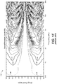
- FIG. 1E illustrates an example measured dispersion pattern for the loudspeaker and waveguide arrangement in FIG. 1D .
- the exit height is 120mm and the exit width, between the waveguides, is 24 mm.
- the horizontal beamwidth holds at approximately 90 degrees between approximately 5 kHz and 14 kHz.
- the beamwidth narrows as the sound wavelength becomes smaller than the width of the exit.
- FIG. IF shows the measured vertical dispersion pattern for the loudspeaker arrangement in FIG. 1D .
- plot 130 above approximately 2.8 kHz the beam narrows as the sound wavelength becomes smaller than the height of the exit.
- Embodiments are directed to a speaker manifold designed to alter a sound wavefront shape from a loudspeaker having a substantially planar driver, comprising a mounting surface configured to attach to a front surface of a case surrounding the driver and having two vertical openings matching corresponding vertical openings in the case to allow sound from the driver to project therethrough, and a waveguide portion coupled to the mounting surface and having a structure channeling sound projected from the driver through the two vertical openings to be combined in one output area, wherein the structure has a plurality of reflective surfaces configured to create output sound that has a consistent dispersion pattern over a defined area.
- the structure comprises two side walls within a manifold frame forming a single large vertical opening, and a central pillar running vertically between the side walls to form the two entry columns and the one output area.
- the reflective surfaces are formed from contours formed into the side walls and corresponding projections formed into the central pillar to form two entry columns representing sound transmission paths for the sound projected from the driver through the two vertical openings, and wherein the output area comprises an outwardly flared sound output area.
- the output area comprises an outwardly angled waveguide forming a dispersion angle along a horizontal axis of the loudspeaker, and wherein the dispersion angle is approximately 90 degrees.
- the sidewalls may be curved inward to form a narrower sound transmission area around a center of the loudspeaker and a wider sound transmission area around opposite ends of the loudspeaker.
- the angled waveguide of the output area may comprise a compound flared structure having a series of flared openings each waveguide angles increased at each additional flaring element.
- the manifold structure is configured to increase at least one of a vertical beamwidth or horizontal beamwidth of the projected sound so that listeners positioned off an axis of the loudspeaker will hear a wide range of frequencies at a substantially similar sound level, the range of frequencies comprising approximately 200Hz to 20kHz.
- the dispersion pattern of the output sound may be symmetric or asymmetric about both the vertical axis and horizontal axis of the loudspeaker.
- the loudspeaker may comprise a dipole speaker having a substantially planar driver disposed on opposite sides of the loudspeaker, where a manifold frame is coupled to each driver, and the manifold frames maybe of the same configuration or different configurations.
- Embodiments are further directed to a method of increasing one or more dispersion angles of a loudspeaker having a substantially planar driver projecting sound through a case having two separate vertical openings, by: directing the sound projected from the two vertical openings into two entry corresponding columns of an acoustic manifold attached to a front surface of the case; channeling the sound through two transmission paths of the two entry columns to combine and form a single sound output; and projecting the single sound output through a flared output area to create output sound that has a consistent dispersion pattern over a defined area of a listening environment.
- the two transmission paths each have a plurality of reflective surfaces formed from a structure comprising two side walls within a manifold frame forming a single large vertical opening, and a central pillar running vertically between the side walls to form the two entry columns and the flared output area.
- the reflective surfaces may be formed from contours formed into the side walls and corresponding projections formed into the central pillar to form two entry columns, and wherein the flared output area comprises an outwardly angled waveguide forming a dispersion angle along a horizontal axis of the loudspeaker.
- the angled waveguide may comprise a compound flared structure having a series of flared openings each waveguide angles increased at each additional flaring element.
- the manifold structure is configured to increase at least one of a vertical beamwidth or horizontal beamwidth of the projected sound so that listeners positioned off an axis of the loudspeaker will hear a wide range of audible frequencies at a substantially similar sound level.
- Embodiments are described for a novel loudspeaker manifold or horn structure that alters the dispersion pattern of a planar magnetic loudspeaker driver. Any of the described embodiments may be used alone or together with one another in any combination.
- the embodiments do not necessarily address any of these deficiencies. In other words, different embodiments may address different deficiencies that may be discussed in the specification. Some embodiments may only partially address some deficiencies or just one deficiency that may be discussed in the specification, and some embodiments may not address any of these deficiencies.
- the term “loudspeaker” means a complete loudspeaker cabinet incorporating one or more loudspeaker drivers; a “driver” or “loudspeaker driver” means a transducer which converts electrical energy into sound or acoustic energy.
- Sound dispersion describes the directional way sound from a source (e.g., a loudspeaker) is dispersed or projected. Wide dispersion, or low directivity, indicates that a source radiates sound widely and fairly consistently in many directions; the widest being omnidirectional where sound radiates in all directions. Narrow dispersion, or high directivity, indicates that a source radiates sound more in one direction and predominantly over a limited angle.
- Dispersion and directivity can be different in different axes (e.g., vertical and horizontal) and can be different at different frequencies. Dispersion can also be asymmetric; that is, the dispersion in one axis can also vary for different angles or directions on another axis.
- beamwidth means the angle between the points where the sound pressure level is 6dB lower than the level in the main direction of aim.
- Embodiments are directed to an acoustic manifold for use with a planar loudspeaker that widens the dispersion, and especially the vertical beamwidth of a planar magnetic loudspeaker driver.
- the device is compact enough that the planar magnetic driver can still be used as the high-frequency driver in front of a larger, low-frequency driver in a coaxial arrangement and without significantly altering the dispersion pattern of the low-frequency driver in the coaxial arrangement.
- FIG. 2 shows, by way of an optical lens example, an effect of beamwidth widening achieved by a loudspeaker manifold under some embodiments.
- a light beam of fixed width when passed through an optical bi-convex lens 204, becomes a light beam with an approximately fixed angle of dispersion.
- a fixed-width acoustic wavefront passes through the acoustic equivalent of a bi-convex lens, resulting in an example wavefront with an angle defined by the acoustic lens.
- the acoustic lens effect is created by specific reflection paths, as shown and described in greater detail below.
- FIG. 3 illustrates a manifold structure for a planar magnetic driver for improved sound dispersion under some embodiments.
- FIG. 3(a) illustrates a back side of manifold 302 and
- FIG. 3(b) illustrates a front side of manifold 302.
- the back side has a surface 304 that is mounted to or placed proximately in front of the diaphragm frame 102 of a planar magnetic loudspeaker.
- Input sound from the planar magnetic driver enters the manifold in the direction shown and through holes 306, and exits through the front side as shown in FIG. 3(b) .
- the size, shape, and arrangement of holes 306 in the manifold 302 are configured to match the hole configuration of the driver.
- the holes 306 are arranged in two columns of 6 holes each denoted entry column A (308a) and entry column B (308b) to correspond to the hole arrangement of a given planar magnetic driver, such as driver 109 in FIG. 1C .
- FIG. 4 shows the manifold of FIG. 3 with an example planar magnetic driver mounted onto the manifold.
- FIG. 4(a) shows how a transducer driver, such as driver 109 of FIG. 1C , is mounted to the back surface 304 of the manifold 302, and
- FIG. 4(b) shows the transducer driver 109 spaced slightly apart from the manifold 302 to show how the holes (e.g., holes 110 in FIG. 1C ) on the driver match the holes 306 on the entry to the manifold.
- FIGS. 4(c) and 4(d) show the back side of the arrangements shown in FIGS. 4(a) and 4(b) , respectively.
- Driver 109 is intended to represent any type of known planar magnetic driver that may be used with manifold 302, though embodiments are not so limited.
- the manifold 302 has two entry columns 308a and 308b, which match the exits of the planar magnetic loudspeaker (e.g., 109) in all dimensions.
- the holes are arranged in two columns with horizontal spacers dividing the entry columns vertically into smaller holes.
- the size of these horizontal spacers or cross-braces is not overly important; and in an embodiment, they are internally sloped to a point to reduce the effects of diffraction at the corresponding spaces on the planar magnetic driver.
- the two columns may be true uninterrupted columns, but spacers are often used exist to strengthen the case and hold the central magnets in place.
- the manifold 302 incorporates curved surfaces to impart an acoustic lens effect, similar to that shown in the optic analog of FIG. 2 .
- FIG. 5 illustrates an arrangement of curved surfaces relative to the manifold openings under some embodiments.
- manifold 502 includes a plurality of sound transmission holes arranged in two columns 308a and 308b. Curved surfaces 504 and 506 are attached to or formed into interior walls of the manifold. The length, curvature, and spacing of the curved surfaces 504 and 506 are selected to impart the desired dispersion effect to the sound as it is output from the driver through manifold 502.
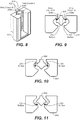
- FIG. 6 illustrates a cross-section view of a manifold having certain surfaces and curved elements under some embodiments.
- manifold 600 has a main frame structure 602 into which may be cut a curved open area 606.
- a central element 604 runs down the length of the manifold frame and provides angled surfaces 100 and 200 for reflection of sound as it passes from the diaphragm and through the manifold.
- FIG. 7 shows the manifold of FIG. 6 with surfaces provided by certain curved elements.
- curved surfaces denoted surfaces 101 and 201 are formed by respective curved elements or members attached to or formed into the frame of manifold 600.
- the surface labels shown in FIGS. 6 and 7 will be used below to show corresponding reflection points as sound passes through the manifold 600.
- FIG. 8 illustrates a cross-section of the manifold of FIG. 6 under some embodiments.
- the manifold comprises the frame 602 and center element 604 that defines the two entry columns 308a and 308b.
- the input sound 802 passes through the two entry columns around the center element 604.
- FIG. 9 illustrates the initial path of the input sound as it enters the manifold of FIG. 8 .
- the sound wavefront entering column A 308a reflects perpendicularly off straight surface 100.
- the sound wavefront entering column B 308b reflects perpendicularly off straight surface 200.
- the wavefront After reflecting off surface 100, the wavefront then reflects off curved surface 101; similarly, wavefront reflected off surface 200 then reflects off curved surface 201, as shown in FIG. 10 .
- surfaces 101 and 201 have the same arc angle. After reflecting of the first curved surfaces 101 and 201, both wavefronts are expanding vertically.
- FIG. 11 shows the path of the sound wavefront after the reflection of FIG. 10 .
- the sound wavefront After reflecting off curved surfaces 101 and 201, the sound wavefront progresses toward the front of the manifold through two interior, curved slots, shown in cross section in FIG. 7a . From this point, the wavefronts are brought back together to a common exit, as shown in FIG. 12.
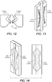
- FIG. 12 shows that the wavefront reflection from surface 101 then reflects off a second curved surface 102 and then reflects off the flat vertical surface 103.
- the wavefront from surface 201 reflects off a second curved surface 202, then reflects off the flat vertical surface 203.
- FIG. 13 illustrates the corresponding surfaces of FIG. 12 for the manifold of FIG. 6 . Sound from both paths 308a and 308b then exit together through the single opening 1202 of the manifold, as shown in FIG. 12.
- FIG. 14 illustrates a manifold with the second curved reflective surfaces 102 and 202 under some embodiments.
- FIG. 15 shows two different cross-sectional of the manifold, with FIG. 15(a) showing a cross-section at the center, and FIG. 15(c) showing a cross-section towards one end.
- the width of each entry column is denoted as W which can be represented in millimeters, inches or some other unit of distance.
- W can be represented in millimeters, inches or some other unit of distance.
- the tunnel widths be the same, again all denoted with a W.
- 15(b) and (d) show the example manifold horizontal tunnel dimensions as just described for each respective cross-section shown in FIGS. 15(a) and 15(c) .
- tunnel as used herein means the void area defined by the manifold frame 602 and center element 604 and represents the path of the sound waves through entry columns A and B (308a, 308b), as they enter the manifold and exit through port or opening 1200.
- FIGS. 16 and 17 illustrate optimum arc angles for the surfaces of the manifold of FIG. 6 under some embodiments.
- FIG. 16 shows a first side of the manifold with columns A (308a) and B (308b), and FIG. 17 shows the opposite side so that the columns 308a and 308b are reversed. Since the wavefront entering at column A reflects of two curved surfaces 101 (in FIG. 16 ) and 102 (in FIG. 17 ) as it passes through the manifold, each curved surface needs to only have an arc angle of approximately half the final desired dispersion angle, as shown in FIG. 17 . For example, for a 60 degree vertical beamwidth, each arc needs to only be approximately 30 degrees.
- FIG. 18 illustrates a desired vertical dispersion angle for a manifold under some embodiments. As shown in FIG. 18 , sound radiates outward in direction 1804 from manifold 1802. The desired dispersion angle 1806 shows the sound radiating outward along the vertical plan of manifold 1802.
- the dimensions of the may be tailored depending on system requirements, and many different configurations and sizes are possible.
- F L For example, for a dispersion angle of 60 degrees and lowest operating frequency of 1 kHz, the optimal mouth width is approximately 417 millimeters.
- FIG. 19 shows a representation of the vertical characteristics of a driver with a certain dispersion angle and corresponding reflection distances for a manifold for the example values given above.
- a distance D1 is the distance from the driver ribbon to the mouth, and D2 is the length created by the manifold sidewalls 1904.
- Diagram 1910 of FIG. 10 shows how the distances D1 and D2 in diagram 1900 relate to the actual manifold, in cross section.
- certain horn flaring techniques can be used to reduce dispersion narrowing.
- FIG. 20 illustrates a diagram of a horn utilizing this horn flaring technique. This empirical method generally involves flaring the last portion of the horn outward, such as flaring the last approximately 1/3 rd of the horn is flared to twice the desired dispersion angle.
- FIG. 20 shows a representation of the vertical characteristics of a flared driver with a certain dispersion angle and corresponding reflection distances for a manifold under an example embodiment.
- Diagram 2000 shows a 180mm planar magnetic driver mounted to a manifold with a vertical dispersion angle of 60 degrees.
- the "lens" 2002 is intended to conceptually represent the curved reflective surfaces and is not an actual element of the speaker or manifold system.
- FIG. 20 illustrates a diagram of a horn utilizing a horn flaring technique that reduces an effect of horn dispersion narrowing. This flared effect can be incorporated into the horn sidewalls 2004 by dividing the distance D 2, shown in FIG.
- Diagram 2010 shows example dimensions for a 180mm length planar magnetic driver and a dispersion angle of 60 degrees. The flared section could extend out the full last 1/3 rd of the ideal horn length L , or stop a little shorter, as shown.
- the manifold brings the two separate columns (A and B) of sound from the planar magnetic driver together to a single vertical exit.
- the manifold's horizontal opening width is the same as the open width of the driver, without the spacing separating the columns.
- the manifold has a 16mm wide exit. This reduction in horizontal width gives more consistent horizontal beamwidth at high frequencies, as shown for example with the beamwidth narrowing in FIG. 1E above 14 kHz.
- FIG. 21A and 21B shows the measured horizontal and vertical dispersion patterns for the same driver as that of FIG. 1E , but with a 90 degree horizontal / 90 degree vertical manifold.
- FIG. 21A shows the measured vertical dispersion pattern of the same driver of FIG. 1F with a 90 degree horizontal / 90 degree vertical manifold.
- FIG. 21B shows the measured vertical dispersion pattern of the same driver of FIG. 1F with a 90 degree horizontal / 90 degree vertical manifold.
- the -6 dB vertical beamwidth is at least 90 degrees and clearly much wider than the driver without manifold shown in the plot of FIG. 1F .
- FIG. 21A shows an example horizontal dispersion pattern for a 120mm planar magnetic loudspeaker with 90 degree horizontal and 90 degree vertical manifold with additional flaring
- FIG. 21B shows an example vertical dispersion pattern for a 120mm planar magnetic driver with a 90 degree horizontal and 90 degree vertical manifold with additional flaring.
- Other manifold and driver configurations may yield different dispersion patterns, but a relative comparison with the default plots of FIGS. 1E and 1F should yield similar results.
- the manifold is generally designed to make a constant beamwidth around + 45 degrees for the 90 degree desired dispersion angle. Other configurations and desired dispersion angles are also possible.
- Embodiments have been described with respect to producing symmetric dispersion for either or both of the vertical and horizontal dispersion patterns. Embodiments may also be directed to producing asymmetric dispersion. Since the shape of the reflection curves predominantly determine the vertical coverage angle and dispersion pattern, shapes other than circular arcs could be used. For example an arc with less curvature at the top and more curvature at the bottom could be used to project more sound energy further from the top the planar magnetic driver to the rear of an audience area, whilst spreading sound energy from the lower part of the planar magnetic driver to the audience sitting proximately below the aiming direction of the driver.
- This variation in vertical dispersion could be combined with variations in the horizontal dispersion of the manifold using variations in the horizontal angle between the sidewalls at the exit, and/or using variations in the manifold exit slot width.
- the upper part of the manifold could have a narrower horizontal beamwidth to help project sound energy further to the rear of an audience area
- the lower part of the manifold could have a wider horizontal beamwidth to better spread sound to the nearer audience.
- Embodiments are directed to planar magnetic drivers, but other loudspeaker drivers can also be used in conjunction with the manifold described and illustrated above.
- Such drivers can be other approximately planar output loudspeaker drivers such as air motion transformers or air velocity transformers and electrostatic loudspeakers. Since these drivers usually have one exit or output area (and not two as for a planar magnetic driver) they generally do not require two paths and two pairs of curved reflection surfaces. In one case, they could use a pair of curved surfaces, similar to one of the right or left half of the manifold described above. Alternatively they could be oriented at approximately 90 degrees to the intended direction of sound and reflect off just one curved surface, which both reflects the sound forward and adds vertical expansion. Furthermore the single curved reflection surface could be shaped to provide wavefront expansion in both axes and even asymmetrical expansion.
- a dipole loudspeaker radiates sound approximately equally both forward and backward, where the rear sound is 180 degrees out of phase relative to the forward sound.
- a simple dipole loudspeaker consists of a loudspeaker driver mounted in a panel, with both the front and rear of the driver open to radiate sound. Little to no sound energy is radiated to the sides, due to the effective cancellation of sound at from both the front and rear of the driver.
- dipole speakers are sometimes preferred over monopole loudspeakers since they are less influenced by room modal behavior and cause less reflections off of the side walls. At high frequencies, sound from the rear can reflect off surfaces and walls behind the loudspeaker, creating a more diffuse sound.
- Dipole planar magnetic drivers are similar to the those described in FIGS. 1A and 1B , except that their cases are open at rear as well as the front.
- a manifold as described above could therefore be used on the rear of the planar magnetic driver to alter the rear dispersion.
- the rear manifold could be the same as the front manifold, or it could be different to the front manifold so as to independently control the front and rear dispersion.
- a front manifold could have a 90 degree horizontal and 30 degree vertical dispersion characteristic to direct sound to an audience area
- the rear manifold could have a wider 120 degree horizontal and 90 degree vertical dispersion characteristic to create greater perception of diffuse sound behind the loudspeaker.
- the rear manifold could be designed to reflect rear sound off the ceiling to accentuate the perception of diffusion.
- the cabinet may be made of medium-density fiberboard (MDF), or other material, such as wood, fiberglass, Perspex, and so on; and it may be made of any appropriate thickness, such as 0.75" (19.05mm) for MDF cabinets.
- MDF medium-density fiberboard
- aspects of the systems described herein may be implemented in an appropriate computer-based sound processing network environment for processing digital or digitized audio files. Portions of the audio system may include one or more networks that comprise any desired number of individual machines.
Claims (12)
- Planares magnetisches Lautsprechersystem, das einen planaren Treiber, ein Gehäuse, das den Treiber umgibt aufweist, und zwei Gehäuseöffnungen aufweist, die zu einer langen Achse des Treibers ausgerichtet sind, und eine Einrichtung zum Verändern einer Schallwellenfrontform aus dem planaren Treiber aufweist, wobei die Einrichtung umfasst:eine Befestigungsfläche, die an einer Frontfläche des Gehäuses angebracht ist und zwei Öffnungen aufweist, die zu den Gehäuseöffnungen passen, um zu ermöglichen, dass Schall aus dem Treiber durch dieselben hindurch projiziert wird; undeinen Wellenleiterabschnitt, der mit der Befestigungsfläche gekoppelt ist und eine Struktur aufweist, die so konfiguriert ist, dass sie Schall, der aus dem Treiber durch die zwei Öffnungen projiziert wird, so kanalisiert, dass er in einem Ausgangsbereich kombiniert wird,wobei die Struktur einen Verteilerrahmen mit zwei Seitenwänden und einer zentralen Säule umfasst, die so zwischen den Seitenwänden verläuft, dass die zwei Öffnungen und der eine Ausgangsbereich gebildet werden,wobei die Struktur eine Vielzahl von reflektierenden Flächen aufweist, die so konfiguriert sind, dass Ausgangsschall erzeugt wird, der ein einheitliches Dispersionsmuster über einen definierten Bereich aufweist, wobei die reflektierenden Flächen von Konturen, die in den Seitenwänden gebildet sind, und entsprechenden Vorsprüngen gebildet werden, die in der zentralen Säule gebildet sind, um Schallübertragungswege für Schall zu bilden, der durch die zwei Öffnungen kanalisiert wird,wobei der eine Ausgangsbereich einen nach außen aufgeweiteten Schallausgangsbereich umfasst,dadurch gekennzeichnet, dass die Seitenwände so nach innen gekrümmt sind, dass um eine Mitte des Lautsprechers herum ein engerer Schallübertragungsbereich, und um gegenüberliegende Enden des Lautsprechers herum ein breiterer Schallübertragungsbereich gebildet wird.
- System nach Anspruch 1, wobei der eine Ausgangsbereich einen nach außen abgewinkelten Wellenleiter umfasst, der entlang einer kurzen Achse des Lautsprechers einen Dispersionswinkel bildet, und wobei der Dispersionswinkel 90 Grad beträgt.
- System nach Anspruch 2, wobei der abgewinkelte Wellenleiter eine zusammengesetzte aufgeweitete Struktur umfasst, die eine Reihe von aufgeweiteten Öffnungen aufweist, wobei alle Wellenleiterwinkel an jedem zusätzlichen Aufweitungselement vergrößert werden.
- System nach Anspruch 1, wobei gekrümmte Flächen der Seitenwände einen Bogenwinkel aufweisen, der die Hälfte des gewünschten Dispersionswinkels beträgt.
- System nach Anspruch 4, wobei die gekrümmten Flächen nicht kreisrunde Bögen sind, um asymmetrische Dispersion zu bilden.
- System nach Anspruch 1, wobei der planare magnetische Treiber ein planarer magnetischer Dipoltreiber ist, der so konfiguriert ist, dass er Schall durch Öffnungen an gegenüberliegenden Seiten des Gehäuses abstrahlt, und wobei mit jeder gegenüberliegenden Seite ein Verteilerrahmen gekoppelt ist, und wobei ein Verteilerrahmen, der mit einer Seite gekoppelt ist, derselbe ist wie der Verteilerrahmen, der mit der gegenüberliegenden Seite gekoppelt ist, oder sich von demselben unterscheidet.
- Verfahren zum Vergrößern eines oder mehrerer Dispersionswinkel eines planaren magnetischen Lautsprechers, der einen planaren Treiber aufweist, welcher Schall durch ein Gehäuse projiziert, das entlang der langen Achse des Treibers zwei getrennte Öffnungen aufweist, wobei das Verfahren umfasst:Lenken des Schalls, der aus den zwei Öffnungen projiziert wird, in zwei Eingangssäulen eines akustischen Verteilers, der an einer Frontfläche des Gehäuses angebracht ist, wobei der Verteiler einen Rahmen mit zwei Seitenwänden und einer zentralen Säule, die so zwischen den Seitenwänden verläuft, dass die zwei Eingangssäulen und ein Ausgangsbereich gebildet werden, und reflektierende Flächen aufweist, die von Konturen, die in den Seitenwänden gebildet sind, und entsprechenden Vorsprüngen gebildet werden, die in der zentralen Säule gebildet sind, um zwei Schallübertragungswege zu bilden;Kanalisieren des Schalls durch die zwei Übertragungswege der zwei Eingangssäulen, um dieselben zu kombinieren und einen einzelnen Schallausgang zu bilden;Projizieren des einzelnen Schallausgangs durch einen aufgeweiteten Ausgangsbereich, um Ausgangsschall zu erzeugen, der ein einheitliches Dispersionsmuster über einen definierten Bereich aufweist;dadurch gekennzeichnet, dass die Seitenwände so nach innen gekrümmt sind, dass um eine Mitte des Lautsprechers herum ein engerer Schallübertragungsbereich, und um gegenüberliegende Enden des Lautsprechers herum ein breiterer Schallübertragungsbereich gebildet wird.
- Verfahren nach Anspruch 7, wobei der aufgeweitete Ausgangsbereich einen nach außen abgewinkelten Wellenleiter umfasst, der entlang einer kurzen Achse des Lautsprechers einen Dispersionswinkel bildet, und einen Dispersionswinkel von 90 Grad aufweist.
- Verfahren nach Anspruch 8, wobei der abgewinkelte Wellenleiter eine zusammengesetzte aufgeweitete Struktur umfasst, die eine Reihe von aufgeweiteten Öffnungen aufweist, wobei alle Wellenleiterwinkel an jedem zusätzlichen Aufweitungselement vergrößert werden.
- Verfahren nach Anspruch 7, wobei gekrümmte Flächen der Seitenwände einen Bogenwinkel aufweisen, der die Hälfte des gewünschten Dispersionswinkels beträgt.
- Verfahren nach Anspruch 10, wobei die gekrümmten Flächen nicht kreisrunde Bögen sind, um asymmetrische Dispersion zu bilden.
- Verfahren nach einem der Ansprüche 7, wobei der Treiber eines aus einem Monopol-Lautsprecher oder einem Dipol-Lautsprecher ist.
Applications Claiming Priority (3)
| Application Number | Priority Date | Filing Date | Title |
|---|---|---|---|
| US201662299323P | 2016-02-24 | 2016-02-24 | |
| US201662354927P | 2016-06-27 | 2016-06-27 | |
| PCT/US2017/018955 WO2017147190A1 (en) | 2016-02-24 | 2017-02-22 | Planar loudspeaker manifold for improved sound dispersion |
Publications (2)
| Publication Number | Publication Date |
|---|---|
| EP3420738A1 EP3420738A1 (de) | 2019-01-02 |
| EP3420738B1 true EP3420738B1 (de) | 2019-11-27 |
Family
ID=58231740
Family Applications (1)
| Application Number | Title | Priority Date | Filing Date |
|---|---|---|---|
| EP17709266.5A Active EP3420738B1 (de) | 2016-02-24 | 2017-02-22 | Planarlautsprecherverteiler für verbesserte schalldispersion |
Country Status (4)
| Country | Link |
|---|---|
| US (1) | US10602263B2 (de) |
| EP (1) | EP3420738B1 (de) |
| CN (1) | CN108781334B (de) |
| WO (1) | WO2017147190A1 (de) |
Families Citing this family (1)
| Publication number | Priority date | Publication date | Assignee | Title |
|---|---|---|---|---|
| US10694281B1 (en) * | 2018-11-30 | 2020-06-23 | Bose Corporation | Coaxial waveguide |
Family Cites Families (26)
| Publication number | Priority date | Publication date | Assignee | Title |
|---|---|---|---|---|
| US4091891A (en) * | 1973-01-17 | 1978-05-30 | Onkyo Kabushiki Kaisha | Horn speaker |
| US3972385A (en) * | 1973-01-17 | 1976-08-03 | Onkyo Kabushiki Kaisha | Horn speaker |
| US5021613A (en) | 1985-09-23 | 1991-06-04 | Gold Ribbon Concepts, Inc. | Ribbon loudspeaker |
| FR2627886B1 (fr) * | 1988-02-29 | 1994-05-13 | Heil Christian | Guide d'onde sonore cylindrique |
| WO1991004643A1 (en) | 1989-09-22 | 1991-04-04 | Anthony Leonard Trufitt | Planar speakers |
| US5900593A (en) * | 1995-07-31 | 1999-05-04 | Adamson; Alan Brock | Loudspeaker system |
| US6104825A (en) | 1997-08-27 | 2000-08-15 | Eminent Technology Incorporated | Planar magnetic transducer with distortion compensating diaphragm |
| EP1194001A4 (de) | 1999-06-11 | 2010-03-10 | Fps Inc | Flacher tonwandler |
| US6343133B1 (en) * | 1999-07-22 | 2002-01-29 | Alan Brock Adamson | Axially propagating mid and high frequency loudspeaker systems |
| JP2001333493A (ja) | 2000-05-22 | 2001-11-30 | Furukawa Electric Co Ltd:The | 平面スピーカ |
| US6581719B2 (en) | 2000-08-02 | 2003-06-24 | Alan Brock Adamson | Wave shaping sound chamber |
| WO2002056293A1 (en) | 2001-01-11 | 2002-07-18 | Meyer Sound Laboratories Incorporated | Manifold for a horn loudspeaker |
| CN2544489Y (zh) * | 2002-05-17 | 2003-04-09 | 陈铮 | 磁致伸缩式高保真平面扬声器 |
| US7316290B2 (en) | 2003-01-30 | 2008-01-08 | Harman International Industries, Incorporated | Acoustic lens system |
| DE20302882U1 (de) | 2003-02-21 | 2004-06-24 | Stamer Musikanlagen Gmbh | Vorrichtung zur Formgestaltung von Schallwellen |
| US8363865B1 (en) | 2004-05-24 | 2013-01-29 | Heather Bottum | Multiple channel sound system using multi-speaker arrays |
| ITBS20050006A1 (it) | 2005-01-28 | 2006-07-29 | Outline Di Noselli G & C S N C | Elemento diffusore del suono per formare sistemi di diffusori in linea verticale a direttivita' regolabile sia orizzontalmente sia verticalmente |
| US7873178B2 (en) | 2005-04-19 | 2011-01-18 | Harman International Industries, Incorporation | Electro-dynamic planar loudspeaker |
| US7903834B1 (en) | 2005-06-03 | 2011-03-08 | Graber Curtis E | Curve fitted electrodynamic planar loudspeaker |
| US7835537B2 (en) | 2005-10-13 | 2010-11-16 | Cheney Brian E | Loudspeaker including slotted waveguide for enhanced directivity and associated methods |
| DE102005051809B3 (de) | 2005-10-27 | 2007-03-22 | Martin Kling | Akustischer Transformer |
| JP4779837B2 (ja) * | 2006-07-05 | 2011-09-28 | ヤマハ株式会社 | スピーカー用振動板及びスピーカー用振動板の製造方法 |
| US8085969B2 (en) | 2006-09-15 | 2011-12-27 | Hpv Technologies, Inc. | Full range planar magnetic microphone and arrays thereof |
| US9111521B2 (en) | 2009-09-11 | 2015-08-18 | Bose Corporation | Modular acoustic horns and horn arrays |
| DK2629551T3 (en) * | 2009-12-29 | 2015-03-02 | Gn Resound As | Binaural hearing aid system |
| ITVR20130147A1 (it) | 2013-06-19 | 2014-12-20 | Angelo Camesasca | Lente acustica |
-
2017
- 2017-02-22 EP EP17709266.5A patent/EP3420738B1/de active Active
- 2017-02-22 CN CN201780013226.7A patent/CN108781334B/zh active Active
- 2017-02-22 US US16/079,300 patent/US10602263B2/en active Active
- 2017-02-22 WO PCT/US2017/018955 patent/WO2017147190A1/en active Application Filing
Non-Patent Citations (1)
| Title |
|---|
| None * |
Also Published As
| Publication number | Publication date |
|---|---|
| CN108781334B (zh) | 2021-04-16 |
| EP3420738A1 (de) | 2019-01-02 |
| US10602263B2 (en) | 2020-03-24 |
| WO2017147190A1 (en) | 2017-08-31 |
| CN108781334A (zh) | 2018-11-09 |
| US20190052956A1 (en) | 2019-02-14 |
Similar Documents
| Publication | Publication Date | Title |
|---|---|---|
| US6996243B2 (en) | Loudspeaker with shaped sound field | |
| US9571923B2 (en) | Acoustic waveguide | |
| US8160268B2 (en) | Loudspeaker array system | |
| EP3062536B1 (de) | Lautsprecheranordnung | |
| EP2894873B1 (de) | Gerillte und längliche Öffnung für akustischen Wandler | |
| US10659872B2 (en) | Speaker apparatus | |
| US20170251296A1 (en) | Loudspeaker with narrow dispersion | |
| US20150110326A1 (en) | Anti-diffraction and phase correction structure for planar magnetic transducers | |
| US20070110269A1 (en) | Biplane Line Array Speaker with Arcuate Tweeter Array Providing Controlled Directivity | |
| WO2006129760A1 (ja) | アレースピーカ装置 | |
| US7426278B2 (en) | Sound device provided with a geometric and electronic radiation control | |
| US4134471A (en) | Narrow angle cylindrical wave full range loudspeaker system | |
| US8917881B2 (en) | Enclosure-less loudspeaker system | |
| EP3420738B1 (de) | Planarlautsprecherverteiler für verbesserte schalldispersion | |
| KR102097891B1 (ko) | 스피커용 입체 음향 가이드 및 이를 구비한 스피커 | |
| US10341761B2 (en) | Acoustic waveguide for audio speaker | |
| FI116506B (fi) | Ympärisäteilevä stereokaiutin | |
| CA2374837C (en) | Loudspeaker | |
| KR100320054B1 (ko) | 원뿔형반사기/결합기스피커시스템및방법 | |
| WO2023174574A1 (en) | Loudspeaker assembly | |
| EP1802163A1 (de) | Lautsprecheranordnung | |
| WO2002091797A1 (en) | Coil driven diaphragm |
Legal Events
| Date | Code | Title | Description |
|---|---|---|---|
| STAA | Information on the status of an ep patent application or granted ep patent |
Free format text: STATUS: UNKNOWN |
|
| STAA | Information on the status of an ep patent application or granted ep patent |
Free format text: STATUS: THE INTERNATIONAL PUBLICATION HAS BEEN MADE |
|
| PUAI | Public reference made under article 153(3) epc to a published international application that has entered the european phase |
Free format text: ORIGINAL CODE: 0009012 |
|
| STAA | Information on the status of an ep patent application or granted ep patent |
Free format text: STATUS: REQUEST FOR EXAMINATION WAS MADE |
|
| 17P | Request for examination filed |
Effective date: 20180924 |
|
| AK | Designated contracting states |
Kind code of ref document: A1 Designated state(s): AL AT BE BG CH CY CZ DE DK EE ES FI FR GB GR HR HU IE IS IT LI LT LU LV MC MK MT NL NO PL PT RO RS SE SI SK SM TR |
|
| AX | Request for extension of the european patent |
Extension state: BA ME |
|
| DAV | Request for validation of the european patent (deleted) | ||
| DAX | Request for extension of the european patent (deleted) | ||
| GRAP | Despatch of communication of intention to grant a patent |
Free format text: ORIGINAL CODE: EPIDOSNIGR1 |
|
| STAA | Information on the status of an ep patent application or granted ep patent |
Free format text: STATUS: GRANT OF PATENT IS INTENDED |
|
| RIC1 | Information provided on ipc code assigned before grant |
Ipc: H04R 9/02 20060101ALI20190528BHEP Ipc: H04R 1/34 20060101ALI20190528BHEP Ipc: H04R 9/06 20060101ALI20190528BHEP Ipc: G10K 11/02 20060101ALI20190528BHEP Ipc: H04R 9/04 20060101AFI20190528BHEP |
|
| INTG | Intention to grant announced |
Effective date: 20190618 |
|
| GRAS | Grant fee paid |
Free format text: ORIGINAL CODE: EPIDOSNIGR3 |
|
| GRAA | (expected) grant |
Free format text: ORIGINAL CODE: 0009210 |
|
| STAA | Information on the status of an ep patent application or granted ep patent |
Free format text: STATUS: THE PATENT HAS BEEN GRANTED |
|
| AK | Designated contracting states |
Kind code of ref document: B1 Designated state(s): AL AT BE BG CH CY CZ DE DK EE ES FI FR GB GR HR HU IE IS IT LI LT LU LV MC MK MT NL NO PL PT RO RS SE SI SK SM TR |
|
| REG | Reference to a national code |
Ref country code: GB Ref legal event code: FG4D |
|
| REG | Reference to a national code |
Ref country code: CH Ref legal event code: EP |
|
| REG | Reference to a national code |
Ref country code: AT Ref legal event code: REF Ref document number: 1208080 Country of ref document: AT Kind code of ref document: T Effective date: 20191215 |
|
| REG | Reference to a national code |
Ref country code: DE Ref legal event code: R096 Ref document number: 602017009144 Country of ref document: DE |
|
| REG | Reference to a national code |
Ref country code: IE Ref legal event code: FG4D |
|
| REG | Reference to a national code |
Ref country code: NL Ref legal event code: MP Effective date: 20191127 |
|
| REG | Reference to a national code |
Ref country code: LT Ref legal event code: MG4D |
|
| PG25 | Lapsed in a contracting state [announced via postgrant information from national office to epo] |
Ref country code: BG Free format text: LAPSE BECAUSE OF FAILURE TO SUBMIT A TRANSLATION OF THE DESCRIPTION OR TO PAY THE FEE WITHIN THE PRESCRIBED TIME-LIMIT Effective date: 20200227 Ref country code: FI Free format text: LAPSE BECAUSE OF FAILURE TO SUBMIT A TRANSLATION OF THE DESCRIPTION OR TO PAY THE FEE WITHIN THE PRESCRIBED TIME-LIMIT Effective date: 20191127 Ref country code: GR Free format text: LAPSE BECAUSE OF FAILURE TO SUBMIT A TRANSLATION OF THE DESCRIPTION OR TO PAY THE FEE WITHIN THE PRESCRIBED TIME-LIMIT Effective date: 20200228 Ref country code: NO Free format text: LAPSE BECAUSE OF FAILURE TO SUBMIT A TRANSLATION OF THE DESCRIPTION OR TO PAY THE FEE WITHIN THE PRESCRIBED TIME-LIMIT Effective date: 20200227 Ref country code: SE Free format text: LAPSE BECAUSE OF FAILURE TO SUBMIT A TRANSLATION OF THE DESCRIPTION OR TO PAY THE FEE WITHIN THE PRESCRIBED TIME-LIMIT Effective date: 20191127 Ref country code: LV Free format text: LAPSE BECAUSE OF FAILURE TO SUBMIT A TRANSLATION OF THE DESCRIPTION OR TO PAY THE FEE WITHIN THE PRESCRIBED TIME-LIMIT Effective date: 20191127 Ref country code: LT Free format text: LAPSE BECAUSE OF FAILURE TO SUBMIT A TRANSLATION OF THE DESCRIPTION OR TO PAY THE FEE WITHIN THE PRESCRIBED TIME-LIMIT Effective date: 20191127 Ref country code: NL Free format text: LAPSE BECAUSE OF FAILURE TO SUBMIT A TRANSLATION OF THE DESCRIPTION OR TO PAY THE FEE WITHIN THE PRESCRIBED TIME-LIMIT Effective date: 20191127 |
|
| PG25 | Lapsed in a contracting state [announced via postgrant information from national office to epo] |
Ref country code: IS Free format text: LAPSE BECAUSE OF FAILURE TO SUBMIT A TRANSLATION OF THE DESCRIPTION OR TO PAY THE FEE WITHIN THE PRESCRIBED TIME-LIMIT Effective date: 20200327 Ref country code: RS Free format text: LAPSE BECAUSE OF FAILURE TO SUBMIT A TRANSLATION OF THE DESCRIPTION OR TO PAY THE FEE WITHIN THE PRESCRIBED TIME-LIMIT Effective date: 20191127 Ref country code: HR Free format text: LAPSE BECAUSE OF FAILURE TO SUBMIT A TRANSLATION OF THE DESCRIPTION OR TO PAY THE FEE WITHIN THE PRESCRIBED TIME-LIMIT Effective date: 20191127 |
|
| PG25 | Lapsed in a contracting state [announced via postgrant information from national office to epo] |
Ref country code: AL Free format text: LAPSE BECAUSE OF FAILURE TO SUBMIT A TRANSLATION OF THE DESCRIPTION OR TO PAY THE FEE WITHIN THE PRESCRIBED TIME-LIMIT Effective date: 20191127 |
|
| PG25 | Lapsed in a contracting state [announced via postgrant information from national office to epo] |
Ref country code: DK Free format text: LAPSE BECAUSE OF FAILURE TO SUBMIT A TRANSLATION OF THE DESCRIPTION OR TO PAY THE FEE WITHIN THE PRESCRIBED TIME-LIMIT Effective date: 20191127 Ref country code: ES Free format text: LAPSE BECAUSE OF FAILURE TO SUBMIT A TRANSLATION OF THE DESCRIPTION OR TO PAY THE FEE WITHIN THE PRESCRIBED TIME-LIMIT Effective date: 20191127 Ref country code: PT Free format text: LAPSE BECAUSE OF FAILURE TO SUBMIT A TRANSLATION OF THE DESCRIPTION OR TO PAY THE FEE WITHIN THE PRESCRIBED TIME-LIMIT Effective date: 20200419 Ref country code: EE Free format text: LAPSE BECAUSE OF FAILURE TO SUBMIT A TRANSLATION OF THE DESCRIPTION OR TO PAY THE FEE WITHIN THE PRESCRIBED TIME-LIMIT Effective date: 20191127 Ref country code: RO Free format text: LAPSE BECAUSE OF FAILURE TO SUBMIT A TRANSLATION OF THE DESCRIPTION OR TO PAY THE FEE WITHIN THE PRESCRIBED TIME-LIMIT Effective date: 20191127 Ref country code: CZ Free format text: LAPSE BECAUSE OF FAILURE TO SUBMIT A TRANSLATION OF THE DESCRIPTION OR TO PAY THE FEE WITHIN THE PRESCRIBED TIME-LIMIT Effective date: 20191127 |
|
| REG | Reference to a national code |
Ref country code: DE Ref legal event code: R097 Ref document number: 602017009144 Country of ref document: DE |
|
| PG25 | Lapsed in a contracting state [announced via postgrant information from national office to epo] |
Ref country code: SM Free format text: LAPSE BECAUSE OF FAILURE TO SUBMIT A TRANSLATION OF THE DESCRIPTION OR TO PAY THE FEE WITHIN THE PRESCRIBED TIME-LIMIT Effective date: 20191127 Ref country code: SK Free format text: LAPSE BECAUSE OF FAILURE TO SUBMIT A TRANSLATION OF THE DESCRIPTION OR TO PAY THE FEE WITHIN THE PRESCRIBED TIME-LIMIT Effective date: 20191127 |
|
| REG | Reference to a national code |
Ref country code: AT Ref legal event code: MK05 Ref document number: 1208080 Country of ref document: AT Kind code of ref document: T Effective date: 20191127 |
|
| REG | Reference to a national code |
Ref country code: CH Ref legal event code: PL |
|
| PLBE | No opposition filed within time limit |
Free format text: ORIGINAL CODE: 0009261 |
|
| STAA | Information on the status of an ep patent application or granted ep patent |
Free format text: STATUS: NO OPPOSITION FILED WITHIN TIME LIMIT |
|
| REG | Reference to a national code |
Ref country code: BE Ref legal event code: MM Effective date: 20200229 |
|
| PG25 | Lapsed in a contracting state [announced via postgrant information from national office to epo] |
Ref country code: MC Free format text: LAPSE BECAUSE OF FAILURE TO SUBMIT A TRANSLATION OF THE DESCRIPTION OR TO PAY THE FEE WITHIN THE PRESCRIBED TIME-LIMIT Effective date: 20191127 Ref country code: LU Free format text: LAPSE BECAUSE OF NON-PAYMENT OF DUE FEES Effective date: 20200222 |
|
| 26N | No opposition filed |
Effective date: 20200828 |
|
| PG25 | Lapsed in a contracting state [announced via postgrant information from national office to epo] |
Ref country code: PL Free format text: LAPSE BECAUSE OF FAILURE TO SUBMIT A TRANSLATION OF THE DESCRIPTION OR TO PAY THE FEE WITHIN THE PRESCRIBED TIME-LIMIT Effective date: 20191127 Ref country code: AT Free format text: LAPSE BECAUSE OF FAILURE TO SUBMIT A TRANSLATION OF THE DESCRIPTION OR TO PAY THE FEE WITHIN THE PRESCRIBED TIME-LIMIT Effective date: 20191127 Ref country code: LI Free format text: LAPSE BECAUSE OF NON-PAYMENT OF DUE FEES Effective date: 20200229 Ref country code: CH Free format text: LAPSE BECAUSE OF NON-PAYMENT OF DUE FEES Effective date: 20200229 Ref country code: SI Free format text: LAPSE BECAUSE OF FAILURE TO SUBMIT A TRANSLATION OF THE DESCRIPTION OR TO PAY THE FEE WITHIN THE PRESCRIBED TIME-LIMIT Effective date: 20191127 |
|
| PG25 | Lapsed in a contracting state [announced via postgrant information from national office to epo] |
Ref country code: IE Free format text: LAPSE BECAUSE OF NON-PAYMENT OF DUE FEES Effective date: 20200222 Ref country code: IT Free format text: LAPSE BECAUSE OF FAILURE TO SUBMIT A TRANSLATION OF THE DESCRIPTION OR TO PAY THE FEE WITHIN THE PRESCRIBED TIME-LIMIT Effective date: 20191127 |
|
| PG25 | Lapsed in a contracting state [announced via postgrant information from national office to epo] |
Ref country code: BE Free format text: LAPSE BECAUSE OF NON-PAYMENT OF DUE FEES Effective date: 20200229 |
|
| PG25 | Lapsed in a contracting state [announced via postgrant information from national office to epo] |
Ref country code: TR Free format text: LAPSE BECAUSE OF FAILURE TO SUBMIT A TRANSLATION OF THE DESCRIPTION OR TO PAY THE FEE WITHIN THE PRESCRIBED TIME-LIMIT Effective date: 20191127 Ref country code: MT Free format text: LAPSE BECAUSE OF FAILURE TO SUBMIT A TRANSLATION OF THE DESCRIPTION OR TO PAY THE FEE WITHIN THE PRESCRIBED TIME-LIMIT Effective date: 20191127 Ref country code: CY Free format text: LAPSE BECAUSE OF FAILURE TO SUBMIT A TRANSLATION OF THE DESCRIPTION OR TO PAY THE FEE WITHIN THE PRESCRIBED TIME-LIMIT Effective date: 20191127 |
|
| PG25 | Lapsed in a contracting state [announced via postgrant information from national office to epo] |
Ref country code: MK Free format text: LAPSE BECAUSE OF FAILURE TO SUBMIT A TRANSLATION OF THE DESCRIPTION OR TO PAY THE FEE WITHIN THE PRESCRIBED TIME-LIMIT Effective date: 20191127 |
|
| PGFP | Annual fee paid to national office [announced via postgrant information from national office to epo] |
Ref country code: FR Payment date: 20230119 Year of fee payment: 7 |
|
| PGFP | Annual fee paid to national office [announced via postgrant information from national office to epo] |
Ref country code: GB Payment date: 20230120 Year of fee payment: 7 Ref country code: DE Payment date: 20230119 Year of fee payment: 7 |
|
| P01 | Opt-out of the competence of the unified patent court (upc) registered |
Effective date: 20230513 |
|
| PGFP | Annual fee paid to national office [announced via postgrant information from national office to epo] |
Ref country code: DE Payment date: 20240123 Year of fee payment: 8 Ref country code: GB Payment date: 20240123 Year of fee payment: 8 |