US9911406B2 - Method and system for large scale audio system - Google Patents
Method and system for large scale audio system Download PDFInfo
- Publication number
- US9911406B2 US9911406B2 US14/683,009 US201514683009A US9911406B2 US 9911406 B2 US9911406 B2 US 9911406B2 US 201514683009 A US201514683009 A US 201514683009A US 9911406 B2 US9911406 B2 US 9911406B2
- Authority
- US
- United States
- Prior art keywords
- transducers
- loudspeaker
- loudspeakers
- control system
- venue
- Prior art date
- Legal status (The legal status is an assumption and is not a legal conclusion. Google has not performed a legal analysis and makes no representation as to the accuracy of the status listed.)
- Active
Links
- 238000000034 method Methods 0.000 title claims description 22
- 238000003491 array Methods 0.000 claims abstract description 50
- 238000012360 testing method Methods 0.000 claims description 19
- 230000003044 adaptive effect Effects 0.000 claims description 18
- 230000015572 biosynthetic process Effects 0.000 claims description 17
- 230000004044 response Effects 0.000 claims description 15
- 230000006870 function Effects 0.000 claims description 12
- 238000012544 monitoring process Methods 0.000 claims description 10
- 230000006835 compression Effects 0.000 abstract description 29
- 238000007906 compression Methods 0.000 abstract description 29
- 238000010276 construction Methods 0.000 description 7
- 238000005259 measurement Methods 0.000 description 6
- 230000008901 benefit Effects 0.000 description 4
- 238000004519 manufacturing process Methods 0.000 description 3
- 230000008569 process Effects 0.000 description 3
- 238000012545 processing Methods 0.000 description 3
- 230000009471 action Effects 0.000 description 2
- 230000004075 alteration Effects 0.000 description 2
- 230000000712 assembly Effects 0.000 description 2
- 238000000429 assembly Methods 0.000 description 2
- 230000008859 change Effects 0.000 description 2
- 230000007704 transition Effects 0.000 description 2
- 238000013459 approach Methods 0.000 description 1
- 230000005540 biological transmission Effects 0.000 description 1
- 238000012937 correction Methods 0.000 description 1
- 230000008878 coupling Effects 0.000 description 1
- 238000010168 coupling process Methods 0.000 description 1
- 238000005859 coupling reaction Methods 0.000 description 1
- 238000013479 data entry Methods 0.000 description 1
- 230000003247 decreasing effect Effects 0.000 description 1
- 230000000994 depressogenic effect Effects 0.000 description 1
- 238000013461 design Methods 0.000 description 1
- 238000010586 diagram Methods 0.000 description 1
- 238000011065 in-situ storage Methods 0.000 description 1
- 238000009434 installation Methods 0.000 description 1
- 230000003993 interaction Effects 0.000 description 1
- 238000003825 pressing Methods 0.000 description 1
- 230000009467 reduction Effects 0.000 description 1
- 230000008439 repair process Effects 0.000 description 1
- 238000000926 separation method Methods 0.000 description 1
- 230000005236 sound signal Effects 0.000 description 1
- 239000000725 suspension Substances 0.000 description 1
- 230000008685 targeting Effects 0.000 description 1
- 238000013024 troubleshooting Methods 0.000 description 1
- 238000013022 venting Methods 0.000 description 1
- 238000012795 verification Methods 0.000 description 1
- 230000000007 visual effect Effects 0.000 description 1
Images


Classifications
-
- G—PHYSICS
- G10—MUSICAL INSTRUMENTS; ACOUSTICS
- G10K—SOUND-PRODUCING DEVICES; METHODS OR DEVICES FOR PROTECTING AGAINST, OR FOR DAMPING, NOISE OR OTHER ACOUSTIC WAVES IN GENERAL; ACOUSTICS NOT OTHERWISE PROVIDED FOR
- G10K11/00—Methods or devices for transmitting, conducting or directing sound in general; Methods or devices for protecting against, or for damping, noise or other acoustic waves in general
- G10K11/18—Methods or devices for transmitting, conducting or directing sound
- G10K11/22—Methods or devices for transmitting, conducting or directing sound for conducting sound through hollow pipes, e.g. speaking tubes
-
- G—PHYSICS
- G10—MUSICAL INSTRUMENTS; ACOUSTICS
- G10K—SOUND-PRODUCING DEVICES; METHODS OR DEVICES FOR PROTECTING AGAINST, OR FOR DAMPING, NOISE OR OTHER ACOUSTIC WAVES IN GENERAL; ACOUSTICS NOT OTHERWISE PROVIDED FOR
- G10K11/00—Methods or devices for transmitting, conducting or directing sound in general; Methods or devices for protecting against, or for damping, noise or other acoustic waves in general
- G10K11/18—Methods or devices for transmitting, conducting or directing sound
- G10K11/26—Sound-focusing or directing, e.g. scanning
-
- H—ELECTRICITY
- H04—ELECTRIC COMMUNICATION TECHNIQUE
- H04R—LOUDSPEAKERS, MICROPHONES, GRAMOPHONE PICK-UPS OR LIKE ACOUSTIC ELECTROMECHANICAL TRANSDUCERS; DEAF-AID SETS; PUBLIC ADDRESS SYSTEMS
- H04R1/00—Details of transducers, loudspeakers or microphones
- H04R1/20—Arrangements for obtaining desired frequency or directional characteristics
- H04R1/22—Arrangements for obtaining desired frequency or directional characteristics for obtaining desired frequency characteristic only
- H04R1/30—Combinations of transducers with horns, e.g. with mechanical matching means, i.e. front-loaded horns
-
- H—ELECTRICITY
- H04—ELECTRIC COMMUNICATION TECHNIQUE
- H04R—LOUDSPEAKERS, MICROPHONES, GRAMOPHONE PICK-UPS OR LIKE ACOUSTIC ELECTROMECHANICAL TRANSDUCERS; DEAF-AID SETS; PUBLIC ADDRESS SYSTEMS
- H04R1/00—Details of transducers, loudspeakers or microphones
- H04R1/20—Arrangements for obtaining desired frequency or directional characteristics
- H04R1/32—Arrangements for obtaining desired frequency or directional characteristics for obtaining desired directional characteristic only
- H04R1/40—Arrangements for obtaining desired frequency or directional characteristics for obtaining desired directional characteristic only by combining a number of identical transducers
- H04R1/403—Arrangements for obtaining desired frequency or directional characteristics for obtaining desired directional characteristic only by combining a number of identical transducers loud-speakers
-
- H—ELECTRICITY
- H04—ELECTRIC COMMUNICATION TECHNIQUE
- H04R—LOUDSPEAKERS, MICROPHONES, GRAMOPHONE PICK-UPS OR LIKE ACOUSTIC ELECTROMECHANICAL TRANSDUCERS; DEAF-AID SETS; PUBLIC ADDRESS SYSTEMS
- H04R1/00—Details of transducers, loudspeakers or microphones
- H04R1/20—Arrangements for obtaining desired frequency or directional characteristics
- H04R1/32—Arrangements for obtaining desired frequency or directional characteristics for obtaining desired directional characteristic only
- H04R1/34—Arrangements for obtaining desired frequency or directional characteristics for obtaining desired directional characteristic only by using a single transducer with sound reflecting, diffracting, directing or guiding means
- H04R1/345—Arrangements for obtaining desired frequency or directional characteristics for obtaining desired directional characteristic only by using a single transducer with sound reflecting, diffracting, directing or guiding means for loudspeakers
-
- H—ELECTRICITY
- H04—ELECTRIC COMMUNICATION TECHNIQUE
- H04R—LOUDSPEAKERS, MICROPHONES, GRAMOPHONE PICK-UPS OR LIKE ACOUSTIC ELECTROMECHANICAL TRANSDUCERS; DEAF-AID SETS; PUBLIC ADDRESS SYSTEMS
- H04R2201/00—Details of transducers, loudspeakers or microphones covered by H04R1/00 but not provided for in any of its subgroups
- H04R2201/34—Directing or guiding sound by means of a phase plug
Definitions
- sound systems for live concert touring are owned by a professional sound provider and travel in one of many tractor/trailer trucks with all the band's production equipment. This can include lighting, video, staging and the band's instruments.
- a variety of speaker types is typically carried on the tour to accommodate the variety of seating arrangements various venues may provide.
- a large line array is used to cover the main audience area and the farthest areas of an arena or stadium.
- Smaller line arrays are used to cover the outer sides and center of the audience area. Additional speakers are then also used on stage to cover the closest audience members.
- each box in the array can be set to a number of different angles relative to the adjacent box; smaller angles increase sound pressure level (SPL), larger angles increase vertical coverage.
- SPL sound pressure level
- acoustic modeling software is used to roughly “draw” the venue prior to the show. This initial look provides a starting point for future modeling, but not the actual angles or orientations of the speakers that need to be implemented on show day.
- a system engineer will arrive early in the morning at the venue to measure the dimensions of the room (typically with a laser range finder), and verify the actual suspension locations and trim height limitations. The venue configuration will then be modified in the modeling software and appropriate array angles and trim heights are chosen. This work must be completed before the loudspeakers can be flown (installed) in the venue.
- the loudspeakers are then flown in the venue. Flying each array is a labor-intensive process. Large format loudspeakers typically weigh in excess of 200 lbs. Inter-cabinet angles must be set between each cabinet, typically at more than one point per cabinet. If angles are set incorrectly or the trim height is incorrect, the system could have non-ideal coverage, or worse, not cover the entire audience. Once all the arrays are flown, connected and powered, the system technician will take acoustical measurements of the system to see how the performance matches their acoustic model. If performance is very poor and time permits, an array might be brought down and reconfigured. However, if time does not permit, typically only system equalization and array alignment delay can be adjusted to improve performance. In extreme cases at least some loudspeakers are unplugged to modify coverage.
- a loudspeaker system includes a plurality of adaptive loudspeakers, each having a housing, a plurality of transducers within the housing, with each of the transducers being individually powered and controlled.
- a digital signal processor channel is provided for each transducer to control the output, including the vertical and/or horizontal directionality of each transducer.
- An electronic network interconnects the digital signal processing channels with each other.
- a control system is provided to monitor and control the operation and performance of the transducers individually.
- the control system includes a computer processor connected to the networked digital signal processing channels and is capable of calculating the loudspeaker output acoustic lobe formation parameters. The control system controls the operation of the transducers based on the calculated loudspeaker output lobe formation parameters.
- the control system controls the digital signal processor channels to direct the acoustic output from the loudspeaker components in desired vertical and/or horizontal directions.
- the control system controls at least one of the gain, delay, and response of each transducer in the loudspeaker, thereby to selectively direct the acoustic output from the loudspeaker in a desired vertical direction to achieve a desired coverage of a venue in which the loudspeaker is located, as well as to selectively direct the acoustic output of the loudspeaker in a desired horizontal direction.
- Each of the loudspeakers includes a self-testing program incorporated into the circuitry of the loudspeaker, whereby to operably verify that the components of the loudspeaker are operating properly.
- the loudspeaker system further includes a plurality of high-frequency transducers in the range of about 1500 Hz to 20 kHz, mid-range transducers in the range of approximately 200 Hz to 2 kHz, and low-frequency transducers in the range of about 30 Hz to 300 Hz.
- the individual loudspeakers may be arranged in a vertical array, with the vertical array in substantially a straight vertical line. Also, vertical arrays of loudspeakers may be positioned side-by-side to each other to achieve a desired horizontal coverage or scope.
- the loudspeakers are also substantially identical in construction, including the same transducer configuration and the same number and type of transducers.
- Proximity sensors are disposed on the loudspeaker to enable the control system to determine the identity and position of each loudspeaker in an array.
- Such proximity sensors may transmit signals in the infrared frequency range, or alternatively ultrasonic or radar-type proximity sensors may be utilized.
- a tilt sensor is positioned within each of the loudspeaker cabinets, thereby to determine the tilt of each loudspeaker cabinet.
- the output of the tilt sensors are actively directed to the control system.
- the self-testing program is incorporated into loudspeakers of the above configuration or into loudspeakers of other configurations.
- the self-test program is operable to verify that the transducers and other components of each loudspeaker are operating properly.
- control system for the loudspeakers of the above configuration, or loudspeakers of other configurations can function to verify the specific location of each loudspeaker with respect to the location in the venue in question.
- the control system generates acoustical impulses from transducers positioned at different locations to trilaterally locate the microphone and thereby determine the distance and direction of the microphone relative to the transducers which generated the acoustical impulses. This helps to verify the configuration of the venue in question.
- proximity sensors may be utilized in conjunction with the loudspeakers described above, or with loudspeakers of other configurations. Such proximity sensors are capable of determining the position of each loudspeaker based on the output signals from the proximity sensors. Such proximity sensors may consist of infrared proximity sensors, ultrasonic proximity sensors, or radar proximity sensors.
- the present disclosure also includes a method for providing sound to a venue, including creating a model of the configuration of the venue, and assembling a plurality of loudspeakers in stacked relationship, and positioning the stacked loudspeakers so that the loudspeakers are disposed in a substantially vertical array.
- Each of said loudspeakers includes transducers and/or drivers, wherein each transducer/driver is operated by a digital signal processor channel.
- the stacked loudspeaker arrays are positioned at one or more locations at the venue.
- Each of the transducers or drivers is operated individually by a control system that networks all the digital processor channels together and also networks the loudspeakers together.
- each of the transducers/drivers is tested and the parameters for each loudspeaker is individually specified.
- the gain, delay, and/or response of each transducer/driver is individually specified, thereby to direct sound emanating from the loudspeaker in desired vertical and/or horizontal directions.
- the method includes assembling two or more vertical arrays of loudspeakers in side-by-side configuration, thereby to achieve the desired horizontal coverage.
- the method also includes utilizing a rigging system to suspend the loudspeakers in substantially a straight line vertical array.
- the method of the present disclosure also utilizes loudspeakers which are substantially identical to each other in construction.
- control system recognizes if a particular transducer/driver is not operational, and then adjusts the output of other operational transducers/drivers to compensate for the non-operational transducer(s)/driver(s).
- FIG. 1 illustrates a front perspective view of a loudspeaker of the present disclosure
- FIG. 2 illustrates the rigging for a loudspeaker array of the present disclosure
- FIG. 3 illustrates loudspeakers of the present disclosure arranged in a vertical array
- FIG. 4 illustrates loudspeakers of the present disclosure arranged in two side-by-side vertical arrays
- FIG. 5 illustrates a front elevational view of a loudspeaker of FIG. 1 shown with portions broken away to view the interior of the loudspeaker;
- FIG. 6 is a rear isometric view of the loudspeaker of FIG. 1 ;
- FIG. 7 is a top plan view of FIG. 1 ;
- FIG. 8 is a bottom view of FIG. 1 ;
- FIG. 9 is a front elevational view of FIG. 1 ;
- FIG. 10 is a rear elevational view of FIG. 1 ;
- FIG. 11 is a side elevational view of FIG. 1 taken from the left side thereof;
- FIG. 12 is a side elevational view of FIG. 1 taken from the right side thereof;
- FIG. 13 illustrates loudspeaker arrays of the present disclosure arranged for a large indoor arena
- FIG. 14 illustrates the use of loudspeaker arrays of the present disclosure configured for an outdoor amphitheater
- FIG. 15 illustrates loudspeaker arrays of the present disclosure configured for a large tent
- FIG. 16 is an isometric view of the high-frequency compression drivers and mid-range cone transducers configured for use in a speaker of the present disclosure, shown without a housing;
- FIG. 17 is a front perspective view of FIG. 16 ;
- FIG. 18 is a view similar to FIG. 17 , but with the addition of a horn wall;
- FIG. 19 is a view similar to FIG. 17 , but from the opposite side from that shown in FIG. 17 ;
- FIG. 20 shows the components of FIGS. 16-19 in partially disassembled condition
- FIG. 21 is a top view of FIG. 16 ;
- FIG. 22 is a side perspective view of FIG. 16 , but with the mid-range cone transducers removed;
- FIG. 23 is a top view of FIG. 22 ;
- FIG. 24 is a rear perspective view of FIG. 22 , but with the horn drivers removed;
- FIG. 25 is a rear elevational view of FIG. 22 ;
- FIG. 26 is a front perspective view of FIG. 22 ;
- FIG. 27 is a front elevational view of FIG. 22 showing the output openings of the high-frequency housing structure
- FIG. 28 is a side elevation view of FIG. 22 ;
- FIG. 29 is a top view of FIG. 22 ;
- FIG. 30 is a schematic of a control system of the present disclosure.
- FIG. 31 is a flow diagram of the installation and operation of an audio system of the present disclosure.
- the present application may include references to directions, such as “forward,” “rearward,” “front,” “back,” “upward,” “downward,” “vertical,” “horizontal,” “upright,” “right-hand,” “left-hand,” “in,” “out,” “extended,” “advanced,” and “retracted.” These references and other similar references in the present application are only to assist in helping describe and understand the present disclosure and invention and are not necessarily intended to limit the present disclosure or invention to these directions.
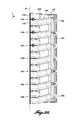
- FIGS. 1 and 2 An audio loudspeaker 100 (also “speaker”) of the present disclosure is shown in FIGS. 1 and 2 as a singular unit and is shown in FIG. 3 as arranged in a vertical array 102 composed of six speakers 100 stacked on top of each other in vertical fashion.
- FIG. 4 a speaker array 104 having two speaker stacks each composed of six speakers, with the two stacks positioned side-by-side to each other.
- FIG. 13 illustrates a speaker array 106 composed of two side-by-side stacks configured for use in a large indoor arena having a stage. One stack consists of 12 speakers 100 , and the second stack consists of six speakers 100 , with the top of the stacks level with each other. The two stacks cover 120 degrees horizontally, but vary in their vertical directivity.
- FIG. 14 illustrates speaker arrays 108 utilized in a large outdoor amphitheater. The arrays 108 are located spaced apart from each other at one end of the amphitheater. Further, FIG.
- the 15 illustrates a speaker array 110 configured for a concert within a very large tent.
- the arrays 110 are in two side-by-side stacks, a first stack consisting of six speakers 100 and the second side-by-side stack composed of two speakers 100 .
- the six-module column covers most of the audience area, and a two-module outer column fills the intermediate near field as well as the side of the venue on which the short stack is positioned.
- the speaker 100 includes a generally trapezoidal-shaped housing 120 composed of two lobe sections 122 that project forwardly and outwardly from the transverse rear section 124 .
- the housing 120 includes side portions 126 and 128 extending rearwardly and diagonally inwardly from the front lobe sections to intersect the transverse rear section 124 .
- a pair of low-frequency cone transducers 130 operating in the range of about 30 Hz to 300 Hz, are housed in the lobe portions 122 of housing 120 .
- the low-frequency transducers 130 occupy substantially the entire height and width of the lobe portions to face forwardly and inwardly toward each other.
- a vertically arranged set 138 of high-frequency compression drivers 142 operating in the range of about 1500 Hz to 20 kHz, are positioned centrally in the housing between the lobe sections to project in the forward direction, see FIG. 5 as well as FIGS. 16, 17, 20-23 .
- the set 138 also includes three mid-frequency cone transducers 143 , operating in the range of about 200 Hz to 2 kHz, that are vertically arranged along each side of the high-frequency drivers 132 , see FIG. 5 as well as FIGS. 16, 17, 19, 20 and 21 . Although three mid-frequency cone transducers 143 are shown on each side of the high-frequency horn, a greater or lesser number of mid-frequency cone transducers 143 may be utilized.
- the forward portion of housing 120 is occupied by the high, mid-range, and low-frequency compression drivers/transducers 142 , 143 , and 130 .
- the power components and control components of the speaker 100 are located in the transverse rear section 124 of the speaker.
- FIGS. 16-29 focus on the high-frequency and mid-frequency drive assembly 138 composed of high-frequency compression drivers 142 and mid-frequency cone transducers 143 . These aspects of the speaker 100 are illustrated and described in U.S. patent application Ser. No. 13/832,817, incorporated herein by reference.
- the high-frequency compression drivers 142 include a horn structure 140 powered by high-frequency drivers 142 .
- the horn structure 140 which loads the compression drivers, includes an array of horn pairs 144 a - 144 g , with the horn pairs stacked in vertical relationship to each other.
- Each horn pair is composed of a left- and right-hand horn designated as 146 L and 146 R as shown, for example, in FIG. 22 .
- the high-frequency driver 142 is mounted to the inlets 148 L and 148 R of horns 146 L and 146 R, respectively.
- a formed mounting plate 150 is disposed between inlets 148 L and 148 R and corresponding drivers 142 .
- the entrance openings or inlets 148 L and 148 R of the horns of each pair 144 are positioned side-by-side to each other.
- the entrance openings 148 L and 148 R are shown as being at the same elevation to each other, but they can be at different elevations to each other.
- the inlets 148 L and 148 R are shown as round in shape, though the inlets do not necessarily have to be round.
- the inlets 148 L and 148 R are angled or canted with respect to a central axis 152 rather than being perpendicular to the axis.
- the angle ⁇ between the central axis 152 and the central axis of inlets 148 L and 148 R can be selected so as to provide enough separation between the drivers 142 to avoid interference therebetween.
- the angle ⁇ is shown in FIG. 29 to be of approximately 17 degrees, but the angle ⁇ can be in the range of 0 to 180 degrees.
- the horn mouths 154 L and 154 R are in directional alignment with a central plane 156 which is in turn aligned with central axis 152 , whereby the horn mouths are disposed in adjacent relationship to each other.
- the horn mouths 154 L and 154 R are stacked on top of each other, with the front of the mouths in vertical alignment.
- the front of the mouths do not have to be in the same vertical plane, but can be staggered fore and aft relative to each other.
- the horn mouths 154 L and 154 R are shown to be in the same rectilinear shape, and more specifically, rectangular in shape, having a width across the mouths that is greater in dimension than the height of the mouths.
- the dimensions of the width and height of the mouths are not directly related, and can be of other relative dimensions. Also, one or both of the width and height of the mouths can be selected based on a desired size of the throat “pinch” before the mouth flare 158 ; see FIG. 23 .
- Each horn 146 L and 146 R includes an elongate throat 160 L and 160 R extending between corresponding inlets 148 L and 148 R and mouths 154 L and 154 R. As shown in the figures, each of the throats 160 L and 160 R extends (curves) diagonally inwardly in the forward direction toward central plane 156 , and also to be in alignment with the central axis 152 at mouths 154 L and 154 R. In addition, the throat 160 R extends (rises upwardly) in a smooth, curved manner a distance equaling the elevation change from the elevation of inlet 148 R to the higher elevation of outlet 154 R.
- throat 160 L descends downwardly a distance corresponding to elevation change of inlet 148 L to the elevation of mouth 154 L.
- Throat 160 L curves in a smooth arc to fold into a position beneath throat 160 R. See FIGS. 22-29 .
- Drivers 142 are constructed with permanent magnets and coils in a known manner of high-frequency drivers. In the present situation, to achieve a lower vertical profile, the permanent magnets utilized in drivers 142 can be square in shape.
- the horn flares 158 can be constructed as a unitary structure to project forwardly from the horn mouths 154 L and 154 R.
- Each of the horn flares 158 is substantially the same shape as the corresponding horn mouths, but flare outwardly in the horizontal direction from the horn mouths, thereby to enhance the horizontal projection of the sounds from the horn mouths.
- the horn flares 158 could be individually constructed rather than constructed as a unitary structure.
- the high-frequency horns are positioned within one-half of a wavelength of each other, thereby enabling control of the interaction between the sources.
- the horn mouths may be 1.0 inch in height and on a 1.0 inch spacing.
- the shape of the housing 120 causes the forwardly directed portion of the housing to function as a large horn for the high-frequency compression drivers and the mid-range transducers.
- the output from the high-frequency transducers 142 passes across the front of the horn wall 170 shown in FIGS. 18 and 19 .
- each of the high-frequency horns is independently powered by a separate transducer.
- each of the high-frequency horns 144 A, 144 B is controlled by a separate DSP channel.
- each of the horns 146 L and 146 R can be individually constructed and then assembled together, the above-described structure for the horn sets 144 a - 144 g enables the horns to be constructed as consolidated subassemblies, for example, one subassembly at each side of the central plane 156 . It is possible to produce the horn structure using permanent molds which are capable of achieving the rather complex shape of the horn structure very economically.
- substantially planar flanges 162 L and 162 R extend vertically along the height of the horn structure at each of the inlets 40 L and 40 R of the horns 146 L and 146 R, respectively.
- the flanges 162 L and 162 R extend laterally outwardly from the inlets 148 L and 148 R, thereby to tie the inlet portions of the horns together and also to provide a mounting structure for drivers 142 .
- the flanges 162 L and 162 R are shown as substantially planar, they can, of course, be in other shapes.
- a plurality of mid-range cone-type transducers 143 are mounted in a vertical array to each side of the horn structure 140 . Although three mid-range cone transducers are illustrated in each vertical array, the number of such cone transducers can be increased or decreased from that illustrated. As shown in FIGS. 17, 18, 19, 20 , and 21 , the transducers 143 are protected in housings 136 . Radial phase plugs 180 are used to load the transducers 143 , extending the usable bandwidth thus facilitating the transition between mid-range and high-frequency transition. Moreover, the output from the transducers 143 passes through diamond-shaped openings 182 formed in the horn wall 170 ; see FIGS. 18 and 19 , to also load the transducers.
- Horn flares 184 are disposed between the phase plugs 180 and the horn wall 170 .
- the horn flares have forwardly directed openings 134 , see also FIG. 5 .
- the structure size and positioning of the mid-range cone transducers 143 enable the output therefrom to sum coherently with the high-frequency wave front generated by the high-frequency compression drivers 142 and helps maintain the desired wave front pattern control while providing horizontal symmetry.
- the mid-range transducers present minimal impact on the high-frequency wave front, allowing the mid-range and high-frequency pass band origins to co-exist in nearly the same point in space without mutual interference.
- Each of the mid-range transducers 143 is independently powered and controlled by a separate DSP channel. Thus, each of the mid-range transducers is independently powered and processed, as are each of the high-frequency compression drivers 143 and low-frequency cone transducers 130 .
- a low-frequency cone transducer 130 is positioned in each of the lobe sections 122 of the housing 120 .
- the low-frequency cone transducers occupy the entire height and width available in the lobe portion of the speaker.
- vertically spaced-apart slots 190 are located in the forward outward portion of the lobes 122 to provide enclosure venting for enhanced performance of the low-frequency transducers 130 .
- vertically spaced slotted vents 192 are also provided in the forward inward portion of the lobe sections 122 to provide a degree of loading on the low-frequency cone transducers, and thereby shifting the apparent low-frequency sound source further apart and extending horizontal pattern control, thereby minimizing the build-up of low-frequency sound energy.
- These apertures 192 , as well as apertures 190 extend outwardly beyond the transducers 130 . This not only extends the uninterrupted surface of the horn, but also pushes the apparent origin of the low-frequency sound sources further apart. The net result is a configuration that provides optimal and consistent horizontal directivity for the size of the speaker housing.
- the effective low-frequency cone transducers spacing is equal to approximately 90 percent of the mid-frequency horn size (the spacing between the inside surfaces of the lobes 122 of housing 120 ) with the horizontal beam width of the low-frequency transducers matched through crossover.
- the mid-frequency horn size the spacing between the inside surfaces of the lobes 122 of housing 120
- the horizontal beam width of the low-frequency transducers matched through crossover.
- easy access manually graspable handles 196 curve around the rear corners of the housing 120 for convenient gripping, for example, when desired to lift or carry the speakers 100 .
- Hand/finger wells 198 are recessed into the rear corner portions of the speaker housing 120 . Because the rear portion of the speaker is much heavier than the forward portion of the speaker, placing the handles 196 in the rear locations, as shown, enables the speaker to be carried in a weight-balanced manner.
- each of the speakers 100 includes four infrared proximity sensors (transmitters/receivers) 200 located at the sides of the housings 120 at the top and bottom thereof.
- infrared proximity sensors transmitter/receivers
- FIGS. 1, 2, 6, 7, 8, 10, 11, and 12 see FIGS. 1, 2, 6, 7, 8, 10, 11, and 12 .
- These infrared sensors enable each of the speaker cabinets to communicate with adjacent cabinets, thereby to determine their relative positions within an array. Consequently, an array of speakers 100 can be fully modeled in software to match the array's physical configuration.
- Other types of proximity sensors can be used in place of infrared sensors, such as ultrasonic or radar based sensors.
- Each of the loudspeakers 100 further includes a test key 201 that queries the loudspeaker for the last known status of the loudspeaker internal electronics. See FIGS. 6 and 10 .
- the test key 201 is located on the control panel 206 at the rear 124 of the housing 120 . This test key 201 is primarily intended for use during set-up of loudspeakers at the venue in question.
- the test key confirms the loudspeaker status based on the most recently performed self-diagnostic. When the test key is depressed, the internal systems of the speaker check the most recent test logs that are held in the speaker's memory. If the system finds no faults (acoustical or electronic), an indicator light 202 adjacent the test key will glow for a fixed time period.
- test key function is powered by a battery internal to the loudspeaker, and thus this particular test can be performed at any time, whether or not the speaker is externally powered or networked with other speakers and connected to the speaker control system 260 , described below.
- each speaker 100 includes a built-in microphone 203 to perform in-situ diagnostics of the speaker, see FIG. 9 .
- diagnostics utilize stored reference curves for the speaker to verify the status of the speaker drivers and transducers. This is intended primarily as a shop function to identify or assist in troubleshooting faults.
- the acoustic measurement function is activated by a software, and is not intended to be used during events.
- each housing 120 houses a calibrated microphone 203 that is used to confirm the operation of each driver and transducer within a loudspeaker 100 , see FIG. 9 .
- the frequency response of each transducer is measured by the front panel microphone and then stored in the speakers' non-volatile memory.
- the frequency response for each driver/transducer is measured and compared to the factory-stored response. If the two measurements vary significantly, the control system 260 provides an alert and recommends a corrective action, for example, driver repair or replacement.
- the measured response for the new component is compared to that of the original component at the time of manufacture. If the new component is within the specifications of the original component, the new response is stored in the non-volatile memory of the speaker in place of the factory-measured response, and on a going-forward basis is used for comparison in future diagnostics. In this manner, it is possible to objectively verify the performance of each driver/transducer in loudspeaker 100 .
- each of the speakers 100 includes a built-in tilt sensor located within the interior of the speaker. This sensor can help establish the hang angle of the speaker array, which should be substantially vertical.
- the tile sensors provide active feedback to the control system 260 of the speaker, described below.
- the speakers 100 can be vertically flown (hung) as shown in FIGS. 3, 4 , and 13 - 15 through the use of flybar latches 210 that fit vertically through slots or rigging channels 212 formed in pairs along each outer side of housing 120 .
- the flybar latches extend through the rigging channels 212 of the top speakers 100 .
- Locking pin actuators 213 are provided interior to and along the sides 126 and 128 of the speaker to engage the flybar latches 210 . These locking pin actuators 213 are activated by exterior rigging pin grips 214 that project rearwardly from each side of the speaker housing 120 .
- the locking pins engage through latch-holes 215 formed in the lower end of the flybar latches.
- flybar latches are attachable to a flybar structure 216 composed of a pair of parallel transverse rearward and forward crossbars 220 and 222 having their corresponding ends connected by side bars 224 and 226 that extend along the outer face of the sides 126 and 128 of the speaker housing.
- crossbars 220 and 222 can be connected to the side bars 224 and 226 by using brackets 227 or other means.
- the entire flybar can be constructed from a singularly welded, cast, or molded unit.
- the construction of the flybar assembly 216 enables vertical speaker arrays to be conveniently jointed together in side-by-side relationship together by placing the corresponding side bars 224 and 226 of adjacent vertical arrays in face-to-face relationship to each other and then securing the corresponding side bars together.
- two adjacent arrays may be initially positioned together through the use of a pin 228 extending outwardly from the forward and rearward portion of side bar 226 .
- the pin 228 has an enlarged and pointed head 229 , to initially engage through a rearward enlarged portion of a slot 230 formed in the side bar 224 .
- the pin can be slid forwardly in the slot 230 to engage a narrower portion 231 of the slot that corresponds substantially to the width or diameter of the pin 228 .
- the side bars 224 and 226 are in substantially a face-to-face position with each other.
- Speakers 100 are conveniently attachable one on top of the other.
- each of the speakers 100 includes rigging latches 232 slidably engageable within slots or rigging channels 212 at the sides of the speaker housings, see FIG. 2 .
- Speakers 100 are attached in stacked relationship by releasing the rigging latches 232 of an upper speaker to engage within the channels 212 of a lower speaker and then the rigging latches 232 are locked in place within the channels 212 of the lower speaker.
- the vertically slidable rigging latches 232 are released by retracting lower latching pins 233 by pulling a pin grip 233 A outwardly, thereby to disengage the latching pin from through holes formed in the upper end portions of the rigging latch 232 .
- the upper latching pins 213 of the lower speaker are disposed in retracted or outward position by manipulating the rigging pin grip 214 thereof.
- the speakers 100 can be quickly and conveniently coupled together in a secure manner without requiring any tools. It will be appreciated that by the foregoing construction, the speakers 100 can be arranged in vertical arrays of any desired height. Also, the components for coupling speakers 100 are “built-in” within the envelope of the speaker housing, which facilitates attaching two or more vertical speaker arrays side-by-side to each other.
- the speakers 100 are flown in vertical relationship to each other, there is no need to position adjacent speakers at an angle relative to the horizontal relative to each other or adjust any angularity between speakers. This greatly simplifies the flying of speaker arrays in terms of required rigging as well as rigging time. As such, the foregoing system for attaching vertically adjacent speakers may be utilized.
- arcuate-shaped stacking pads 240 are positioned on the top of each lobe section 122 .
- the size and shape of the stacking pads 240 matches grooves 242 formed in the underside of the housing lobe sections 122 ; see FIG. 8 . In this manner, the pads 240 locate vertically adjacent speakers one to another and assist in maintaining the speakers stationary relative to each other in the horizontal directions.
- a vertical alignment line 244 extends vertically along the inside surfaces of each lobe section 122 adjacent grill 246 , which covers the central portion of the front of the speaker.
- the alignment line 244 can serve as a visual indication of whether or not the speakers 100 of a vertical array are all in alignment with each other. As shown in FIGS. 3 and 4 , when the speakers are in alignment, the alignment line 244 of the speakers form a continuous uniform, vertical line along the height of the array.
- the alignment line 244 can be of a color distinctive from the adjacent portion of the speaker housing so as to improve the visibility of the alignment line.
- each of the high-frequency compression drivers 142 as well as each of the mid-range cone transducers 143 and each of the low-frequency cone transducers 130 is individually powered as well as individually controlled.
- This is schematically illustrated in FIG. 30 .
- a digital signal processor (DSP) 250 channel that operates in conjunction with adaptive performance software 252 .
- DSP digital signal processor
- This software assists in generating optimal DSP control parameters for the compression drivers 142 and cone transducers 143 and 130 by generating particular acoustic lobe configurations.
- the control signal from the DSP 250 is routed through a digital-to-analog converter 254 and then through a power amplifier 256 , and then to the high-frequency, mid-range, and low-frequency compression drivers/cone transducers.
- the adaptive performance software by generating desired or optimal DSP control parameters for the compression drivers and cone transducers, is able to steer or direct the output from the compression drivers and cone transducers in the vertical and horizontal directions.
- the signal from the high-frequency compression drivers and mid and low-frequency cone transducers can be directed between any angle or angle range in the vertical direction from essentially straight down to straight up and anywhere therebetween.
- the angular output in the horizontal direction of the compression drivers and cone transducers can be directed in about a 60° range.
- a control system 260 is provided that is capable of controlling the gain, delay, and response of speaker systems.
- the control system 260 has a delay subsystem 262 for controlling the delay of the system.
- the control system 260 also has a parametric equalizer 264 as well as a high pass filter 266 and a low pass filter 268 to control the output produced by the system.
- the control system 260 further includes a subsystem 270 to alter the gain and polarity of the output from the system.
- the control system 260 has the ability to mute the output from the system via subsection 272 .
- Input of digital audio signals to the control system 260 can be via AES/EBU (AES3) port 273 routed through an analog-to-digital converter 274 .
- AES3/EBU (AES3) port 273 routed through an analog-to-digital converter 274 .
- the input to the controller 260 , as well as output therefrom, also may be routed through Dante enabled ports 276 .
- the Dante ports also function as the network interface to the control system 260 .
- the exemplary methodology at step 300 includes first creating a definition of the venue, then, at step 310 , determining the array or arrays of speakers 100 to match the venue. In this regard, the array coverage pattern is optimized to the venue based in part on the calculated ideal wave front.
- the arrays are flown at step 320 , and then at steps 330 and 340 each of the drivers/transducers of each speaker is electronically adjusted and tuned to the venue. In this regard, the operational parameters of the speakers are determined and then set.
- the output of the system can be tested at various locations of the venue at step 360 and if needed, the output of the speaker and its components can be adjusted at step 365 . Also during the use of the speakers, the output of each driver/transducer in each speaker is continuously monitored, and, if need be, adjustments made thereto, see steps 370 and 380 .
- the definition of the performance venue is “drawn” in software using dimensional information available pertaining to the venue, including its length, width, seating areas, stage elevation and position and size, balcony locations and positions, etc.
- the venue configuration can be confirmed by using one or more microphones positioned at one or more points in the venue, see step 350 .
- the audio system of the present disclosure generates several impulses from the high-frequency compression drivers and/or mid/low-frequency cone transducers at different plural locations.
- the system of the present disclosure trilaterates the location of the microphone. This information assists in modifying a preference or making corrections to the venue model. It will be appreciated that by using this trilateration function, it is no longer necessary to make manual measurements of the venue and carry out the associated numeric data entry of such measurements.
- one or more loudspeaker arrays are configured to match the venue in question, including matching the size and the shape of the venue, as well as the locations of the audience members and based on the ideal wave front for the venue.
- algorithms have been developed to model the output of the loudspeakers 100 and each compression driver/cone transducer thereof not only to provide sound to all desired areas of a venue, but also to achieve pleasing results.
- the venue is divided into a grid of spots and the loudspeakers are armed to direct sound to each such spot.
- the loudspeaker arrays are constructed from identical speakers 100 and the rigging system, described above, is used to quickly and conveniently construct and position the arrays at the venue.
- the operating parameters for each of the high-frequency compression drivers as well as the mid- and low-frequency cone transducers of each loudspeaker are determined to optimize the speakers to the venue.
- each such compression driver and cone transducer is independently powered and processed.
- the control system of the present disclosure is aware of the location of each of the speakers 100 .
- four infrared or other type of proximity transceivers 200 are mounted on each speaker housing 120 .
- the transceivers are located two at the top and two at the bottom of the speaker housing on opposite sides of the speaker housing, which enables the speakers to be modeled as two-dimensional arrays. With this information, the physical layout of the loudspeakers is determined.
- each loudspeaker includes a tilt sensor 204 to confirm that the loudspeaker in question is vertical positioned, or whether the loudspeaker is at an angle off vertical. This information is also useful in adjusting or targeting the output from each speaker.
- each high-frequency compression driver and each mid-range and low-frequency cone transducer can be steered in the vertical direction to achieve the best audience coverage.
- the vertical angle directional output with the drivers and transducers is adaptive throughout the entire 180° range of from vertically down to vertically up. It will be appreciated that the spacing between each of the high-frequency compression drivers, as well as each of the speakers, is minimized so as to maximize the vertical lobe alteration within the speakers' operational bandwidth, and thereby minimize vertical artifacts.
- the output of the transducers and drivers is controlled to provide the device horizontal coverage.
- the spacing between each horizontally adjacent transducer is also minimal, to maximize horizontal lobe alteration within that transducer's operational bandwidth, and to minimize horizontal artifacts.
- the nominal horizontal beam width of speakers 100 is approximately 70 degrees. This beam width can be increased up to 360 degrees by using multiple columns of speakers 100 .
- each of the speakers 100 within an array is networked together, and thus the controls for each of the compression drivers and cone transducers of each speaker, via a computer processor which operates a DSP as well as applicable algorithms to control the output and directionality of each of the transducers in each of the speakers.
- a computer processor which operates a DSP as well as applicable algorithms to control the output and directionality of each of the transducers in each of the speakers.
- Such computer processor calculates all of the lobe formation parameters for the speakers and communicates them to the loudspeakers.
- the networked control system also monitors the operation and performance of all of the loudspeaker compression drivers and cone transducers in the arrays on an ongoing basis, see step 370 . Since the performance parameters for the loudspeaker components are sent electronically to the loudspeaker components from the control system, such parameters can be modified very quickly at any time. Some of the monitored parameters include transducer impedance, amplifier temperature, voltage, and currents of each driver/transducer, and this information is recorded on a “live” status log that can be downloaded. In this regard, not only is the functionality of each compression driver and cone transducer confirmed, but also the control system assesses the complete performance of each compression driver/cone transducer by comparing such performance with reference parameters stored in memory. Also, follow up or supplementary venue measurements can be conducted at any time, as discussed above, thereby to more accurately define the venue. For example, if additional seats in the venue are sold, or the performers are not satisfied with the sound quality, the coverage from the speakers can be easily modified.
- the above methodology can be used to design the speaker configurations for the venues shown in FIGS. 13, 14, and 15 .
- the nature of the “coverage” achieved at the venue is shown in FIGS. 13-15 , wherein the various cross-batching corresponds to the sound level achieved at the various locations of the depicted venue.
- FIG. 13 is a large indoor arena having multiple levels. Two substantial columns of speakers are used to cover the disparate requirements of the venue. Each of the arrays covers 120 horizontal degrees, but with varying the vertical directivity from column-to-column. Nonetheless, the arrays deliver the audio at the venue as a single integrated entity.
- two speaker arrays are utilized to cover a very large, steeply raked outdoor amphitheater.
- the speakers are capable of delivering audio over the entire amphitheater within +/ ⁇ 2 decibels.
- the vertical directivity of the speakers is directed upwardly sufficiently to reach the back of the amphitheater while spilling off the lower forward section of the amphitheater.
- FIG. 15 depicts a large tent utilizing two arrays composed of a six-module main column which covers most of the area and is pointed to the unit's far corner on two-module outer column that fills the immediate near-field and house-left.
- each loudspeaker can be tested, since each loudspeaker contains a self-test function built into the circuitry of the loudspeaker system to enable verification that all the components of the loudspeaker are operating correctly. The results of this test can be queried by simply pressing a self-test button on the loudspeaker.
- the control system will determine a solution and adjust the system coverage in response. Essentially, the control system is able to rebuild the acoustical model of the loudspeaker components without the “failed” sources.
- compression drivers and cone transducers parameters can be adjusted to affect the vertical direction between adjacent speakers and direct sound at every “spot” in the venue. Therefore, “spots” to be hit are redefined to adjust to the non-functioning drivers/transducers. If a particular loudspeaker or component thereof cannot “hit” every desired spot in the venue, then adjacent loudspeakers, drivers, and/or transducers are used to “fill in” the sound to achieve the desired coverage.
- the speaker 100 and the arrays constructed therewith as well as the control system for the arrays described above provide significant advantages over preexisting loudspeaker arrays.
- the position of each loudspeaker itself is self-recognizing, and all of the drivers/transducers in each loudspeaker are networked together and individually powered and controlled for output level as well as for horizontal and vertical directionality.
- the present loudspeaker system is “self-healing” and adapts if one or more component failures occur, even during use.
- the rigging of the loudspeaker arrays is simplified and thus the arrays can be flown quickly and easily and also disassembled quickly and easily.
- loudspeaker 100 is illustrated and described herein as composed of 14 high-frequency transducers, six mid-range transducers and two low-frequency transducers, the number of high-frequency, mid-range and low-frequency transducers can be altered or modified. Regardless of the numbers of the various transducers used, what is of significance is the close and relative arrangement of the transducers and drivers, the manner of their loading using horns, horn walls, horn flairs, phase plugs, and other structures, and that they are each individually controlled.
- loudspeaker 100 and the various arrays that may be constructed therefrom provide significant advances and advantages.
- each of the loudspeakers of the array can be of identical construction, thereby minimizing the need for spare components or parts.
- the loudspeakers are arrayed in a vertical arrangement, and are “dead hung,” thereby simplifying the flying of the arrays. In this regard, there are no vertical splay angles to adjust.
- the speakers 100 create a radial coverage pattern that is very narrowly focused.
- the tuning of the drivers and transducers of the loudspeakers is carried out electronically, and thus the parameters for the transducers and drivers can be conveniently and rapidly specified, as well as adjusted. This also enables the drivers and transducers in speaker 100 to adjust if any of the drivers and transducers fail during use. Further, the speakers 100 enable the arrays to be precisely configured to a particular venue and also enable the system to be scaleable to a particular venue.
- loudspeaker 100 and the arrays composed thereof enable the loudspeaker and arrays to produce a continuous and consistent beam width versus frequency characteristic over the entire working frequency range of a loudspeaker. Further, the loudspeaker 100 and the arrays composed thereof exhibit continuous and consistent directional pattern characteristics versus frequency output from the loudspeaker, while occupying a relatively small amount of physical space, especially for the level of output generated by the loudspeaker.
Landscapes
- Physics & Mathematics (AREA)
- Engineering & Computer Science (AREA)
- Acoustics & Sound (AREA)
- Health & Medical Sciences (AREA)
- Otolaryngology (AREA)
- Signal Processing (AREA)
- Multimedia (AREA)
- Circuit For Audible Band Transducer (AREA)
Abstract
Description
Claims (20)
Priority Applications (2)
| Application Number | Priority Date | Filing Date | Title |
|---|---|---|---|
| US14/683,009 US9911406B2 (en) | 2013-03-15 | 2015-04-09 | Method and system for large scale audio system |
| US14/727,780 US9661418B2 (en) | 2013-03-15 | 2015-06-01 | Method and system for large scale audio system |
Applications Claiming Priority (4)
| Application Number | Priority Date | Filing Date | Title |
|---|---|---|---|
| US13/832,817 US9219954B2 (en) | 2013-03-15 | 2013-03-15 | Acoustic horn manifold |
| US201461977602P | 2014-04-09 | 2014-04-09 | |
| US14/489,340 US9215524B2 (en) | 2013-03-15 | 2014-09-17 | Acoustic horn manifold |
| US14/683,009 US9911406B2 (en) | 2013-03-15 | 2015-04-09 | Method and system for large scale audio system |
Related Parent Applications (1)
| Application Number | Title | Priority Date | Filing Date |
|---|---|---|---|
| US14/489,340 Continuation-In-Part US9215524B2 (en) | 2013-03-15 | 2014-09-17 | Acoustic horn manifold |
Related Child Applications (1)
| Application Number | Title | Priority Date | Filing Date |
|---|---|---|---|
| US14/727,780 Continuation-In-Part US9661418B2 (en) | 2013-03-15 | 2015-06-01 | Method and system for large scale audio system |
Publications (2)
| Publication Number | Publication Date |
|---|---|
| US20150289050A1 US20150289050A1 (en) | 2015-10-08 |
| US9911406B2 true US9911406B2 (en) | 2018-03-06 |
Family
ID=54210914
Family Applications (1)
| Application Number | Title | Priority Date | Filing Date |
|---|---|---|---|
| US14/683,009 Active US9911406B2 (en) | 2013-03-15 | 2015-04-09 | Method and system for large scale audio system |
Country Status (1)
| Country | Link |
|---|---|
| US (1) | US9911406B2 (en) |
Cited By (1)
| Publication number | Priority date | Publication date | Assignee | Title |
|---|---|---|---|---|
| US11463807B2 (en) * | 2018-07-19 | 2022-10-04 | L-Acoustics | Sound diffusion device with fixed non-constant curvature |
Families Citing this family (11)
| Publication number | Priority date | Publication date | Assignee | Title |
|---|---|---|---|---|
| US20160119705A1 (en) * | 2014-08-01 | 2016-04-28 | John Ramirez | Universal smart mobile electronic gear hub and specialty earphone case |
| JP7359528B2 (en) * | 2014-10-10 | 2023-10-11 | ジーディーイー エンジニアリング プティ リミテッド | Method and apparatus for providing customized acoustic distribution |
| DE102014227053B4 (en) * | 2014-12-31 | 2021-05-27 | Adam Hall Gmbh | Loudspeaker box arrangement and loudspeaker box |
| USD776638S1 (en) | 2015-02-19 | 2017-01-17 | Adam Hall Gmbh | Loudspeaker |
| USD813838S1 (en) | 2015-04-14 | 2018-03-27 | Adam Hall Gmbh | Loudspeaker |
| USD832235S1 (en) * | 2016-07-25 | 2018-10-30 | Bose Corporation | Sub-woofer |
| FR3062233B1 (en) * | 2017-01-24 | 2020-03-20 | L-Acoustics | SOUND BROADCASTING SYSTEM |
| US10129644B2 (en) * | 2017-01-30 | 2018-11-13 | Loud Audio, Llc | Systems and methods for adaptive zone control of a large scale audio system |
| US10225648B1 (en) * | 2018-01-17 | 2019-03-05 | Harman International Industries, Incorporated | Horn array |
| US10618443B2 (en) * | 2018-02-01 | 2020-04-14 | GM Global Technology Operations LLC | Method and apparatus that adjust audio output according to head restraint position |
| DE102022111521A1 (en) * | 2022-05-09 | 2023-11-09 | Holoplot Gmbh | Carrier system for sound transducers |
Citations (33)
| Publication number | Priority date | Publication date | Assignee | Title |
|---|---|---|---|---|
| US1752526A (en) | 1926-07-03 | 1930-04-01 | Columbia Phonograph Co Inc | Sound amplifier |
| US2058132A (en) | 1934-04-06 | 1936-10-20 | Cirelli Frank | Sound box for amplifying horns with loudspeakers |
| US4344504A (en) | 1981-03-27 | 1982-08-17 | Community Light & Sound, Inc. | Directional loudspeaker |
| US4629029A (en) | 1985-11-15 | 1986-12-16 | Electro-Voice, Inc. | Multiple driver manifold |
| JPS63236498A (en) | 1987-03-25 | 1988-10-03 | Hisaji Nakamura | Speaker device |
| US4923031A (en) | 1986-02-26 | 1990-05-08 | Electro-Voice, Incorporated | High output loudspeaker system |
| GB2230682A (en) | 1989-04-11 | 1990-10-24 | Hisatsugu Nakamura | Speaker and horn array |
| US5070530A (en) | 1987-04-01 | 1991-12-03 | Grodinsky Robert M | Electroacoustic transducers with increased magnetic stability for distortion reduction |
| US5519572A (en) | 1994-11-29 | 1996-05-21 | Luo; Hsin-Yi | Computer peripheral apparatus |
| US5715322A (en) | 1992-08-25 | 1998-02-03 | Toa Corporation | Throat device interconnecting a plurality of drive units and a horn |
| US5996728A (en) * | 1999-04-13 | 1999-12-07 | Eastern Acoustic Works, Inc. | Modular speaker cabinet including an integral rigging system |
| US6035051A (en) | 1997-05-12 | 2000-03-07 | Sony Corporation | Sound apparatus |
| US6112847A (en) | 1999-03-15 | 2000-09-05 | Clair Brothers Audio Enterprises, Inc. | Loudspeaker with differentiated energy distribution in vertical and horizontal planes |
| US6118883A (en) | 1998-09-24 | 2000-09-12 | Eastern Acoustic Works, Inc. | System for controlling low frequency acoustical directivity patterns and minimizing directivity discontinuities during frequency transitions |
| US20020038740A1 (en) | 2000-05-30 | 2002-04-04 | Ureda Mark S. | Cross-fired multiple horn loudspeaker system |
| US6385322B1 (en) * | 1997-06-20 | 2002-05-07 | D & B Audiotechnik Aktiengesellschaft | Method and device for operation of a public address (acoustic irradiation) system |
| US6393131B1 (en) | 2000-06-16 | 2002-05-21 | Scott Michael Rexroat | Loudspeaker |
| US6394223B1 (en) | 1999-03-12 | 2002-05-28 | Clair Brothers Audio Enterprises, Inc. | Loudspeaker with differential energy distribution in vertical and horizontal planes |
| US20030132056A1 (en) | 2001-01-11 | 2003-07-17 | Meyer John D. | Manifold for a horn loudspeaker and method |
| US20040218773A1 (en) | 2003-03-20 | 2004-11-04 | Andrews Anthony J. | Loudspeaker array |
| USD500025S1 (en) | 2003-02-25 | 2004-12-21 | Nexo | Loud speaker |
| USD500306S1 (en) | 2002-07-09 | 2004-12-28 | Outline Di Noselli G. & C. S.N.C. | Acoustic box line array unit |
| US20060169530A1 (en) | 2005-01-28 | 2006-08-03 | Guido Noselli | Loudspeaker enclosure element for forming vertical line array systems with adjustable horizontal and vertical directivity |
| US7392880B2 (en) | 2002-04-02 | 2008-07-01 | Gibson Guitar Corp. | Dual range horn with acoustic crossover |
| JP2009065609A (en) | 2007-09-10 | 2009-03-26 | Panasonic Corp | Speaker device |
| US7590257B1 (en) | 2004-12-22 | 2009-09-15 | Klipsch, Llc | Axially propagating horn array for a loudspeaker |
| US20110069856A1 (en) | 2009-09-11 | 2011-03-24 | David Edwards Blore | Modular Acoustic Horns and Horn Arrays |
| US20110222698A1 (en) | 2010-03-12 | 2011-09-15 | Panasonic Corporation | Noise reduction device |
| US20110305347A1 (en) | 2010-06-14 | 2011-12-15 | Michael Wurm | Adaptive noise control |
| US8199953B2 (en) | 2008-10-30 | 2012-06-12 | Avago Technologies Wireless Ip (Singapore) Pte. Ltd. | Multi-aperture acoustic horn |
| US8224001B1 (en) | 2007-12-21 | 2012-07-17 | Waller Jon J | Line array loudspeaker |
| US20120213387A1 (en) | 2011-02-18 | 2012-08-23 | David Edwards Blore | Acoustic Horn Gain Managing |
| US8275160B2 (en) * | 2008-05-21 | 2012-09-25 | Yamaha Corporation | Delay time calculation apparatus, delay time calculation method, and storage medium storing program therefor |
-
2015
- 2015-04-09 US US14/683,009 patent/US9911406B2/en active Active
Patent Citations (36)
| Publication number | Priority date | Publication date | Assignee | Title |
|---|---|---|---|---|
| US1752526A (en) | 1926-07-03 | 1930-04-01 | Columbia Phonograph Co Inc | Sound amplifier |
| US2058132A (en) | 1934-04-06 | 1936-10-20 | Cirelli Frank | Sound box for amplifying horns with loudspeakers |
| US4344504A (en) | 1981-03-27 | 1982-08-17 | Community Light & Sound, Inc. | Directional loudspeaker |
| US4629029A (en) | 1985-11-15 | 1986-12-16 | Electro-Voice, Inc. | Multiple driver manifold |
| US4923031A (en) | 1986-02-26 | 1990-05-08 | Electro-Voice, Incorporated | High output loudspeaker system |
| JPS63236498A (en) | 1987-03-25 | 1988-10-03 | Hisaji Nakamura | Speaker device |
| US5070530A (en) | 1987-04-01 | 1991-12-03 | Grodinsky Robert M | Electroacoustic transducers with increased magnetic stability for distortion reduction |
| GB2230682A (en) | 1989-04-11 | 1990-10-24 | Hisatsugu Nakamura | Speaker and horn array |
| US5715322A (en) | 1992-08-25 | 1998-02-03 | Toa Corporation | Throat device interconnecting a plurality of drive units and a horn |
| US5519572A (en) | 1994-11-29 | 1996-05-21 | Luo; Hsin-Yi | Computer peripheral apparatus |
| US6035051A (en) | 1997-05-12 | 2000-03-07 | Sony Corporation | Sound apparatus |
| US6385322B1 (en) * | 1997-06-20 | 2002-05-07 | D & B Audiotechnik Aktiengesellschaft | Method and device for operation of a public address (acoustic irradiation) system |
| US6118883A (en) | 1998-09-24 | 2000-09-12 | Eastern Acoustic Works, Inc. | System for controlling low frequency acoustical directivity patterns and minimizing directivity discontinuities during frequency transitions |
| US6394223B1 (en) | 1999-03-12 | 2002-05-28 | Clair Brothers Audio Enterprises, Inc. | Loudspeaker with differential energy distribution in vertical and horizontal planes |
| US6112847A (en) | 1999-03-15 | 2000-09-05 | Clair Brothers Audio Enterprises, Inc. | Loudspeaker with differentiated energy distribution in vertical and horizontal planes |
| US5996728A (en) * | 1999-04-13 | 1999-12-07 | Eastern Acoustic Works, Inc. | Modular speaker cabinet including an integral rigging system |
| US20020038740A1 (en) | 2000-05-30 | 2002-04-04 | Ureda Mark S. | Cross-fired multiple horn loudspeaker system |
| US6712177B2 (en) | 2000-05-30 | 2004-03-30 | Mark S. Ureda | Cross-fired multiple horn loudspeaker system |
| US6393131B1 (en) | 2000-06-16 | 2002-05-21 | Scott Michael Rexroat | Loudspeaker |
| US20030132056A1 (en) | 2001-01-11 | 2003-07-17 | Meyer John D. | Manifold for a horn loudspeaker and method |
| US6668969B2 (en) | 2001-01-11 | 2003-12-30 | Meyer Sound Laboratories, Incorporated | Manifold for a horn loudspeaker and method |
| US7392880B2 (en) | 2002-04-02 | 2008-07-01 | Gibson Guitar Corp. | Dual range horn with acoustic crossover |
| USD500306S1 (en) | 2002-07-09 | 2004-12-28 | Outline Di Noselli G. & C. S.N.C. | Acoustic box line array unit |
| USD500025S1 (en) | 2003-02-25 | 2004-12-21 | Nexo | Loud speaker |
| US20040218773A1 (en) | 2003-03-20 | 2004-11-04 | Andrews Anthony J. | Loudspeaker array |
| US7454029B2 (en) | 2003-03-20 | 2008-11-18 | Andrews Anthony J | Loudspeaker array |
| US7590257B1 (en) | 2004-12-22 | 2009-09-15 | Klipsch, Llc | Axially propagating horn array for a loudspeaker |
| US20060169530A1 (en) | 2005-01-28 | 2006-08-03 | Guido Noselli | Loudspeaker enclosure element for forming vertical line array systems with adjustable horizontal and vertical directivity |
| JP2009065609A (en) | 2007-09-10 | 2009-03-26 | Panasonic Corp | Speaker device |
| US8224001B1 (en) | 2007-12-21 | 2012-07-17 | Waller Jon J | Line array loudspeaker |
| US8275160B2 (en) * | 2008-05-21 | 2012-09-25 | Yamaha Corporation | Delay time calculation apparatus, delay time calculation method, and storage medium storing program therefor |
| US8199953B2 (en) | 2008-10-30 | 2012-06-12 | Avago Technologies Wireless Ip (Singapore) Pte. Ltd. | Multi-aperture acoustic horn |
| US20110069856A1 (en) | 2009-09-11 | 2011-03-24 | David Edwards Blore | Modular Acoustic Horns and Horn Arrays |
| US20110222698A1 (en) | 2010-03-12 | 2011-09-15 | Panasonic Corporation | Noise reduction device |
| US20110305347A1 (en) | 2010-06-14 | 2011-12-15 | Michael Wurm | Adaptive noise control |
| US20120213387A1 (en) | 2011-02-18 | 2012-08-23 | David Edwards Blore | Acoustic Horn Gain Managing |
Non-Patent Citations (20)
| Title |
|---|
| "Airline LA12: 3-Way Symmetrical High Output Line Array System," Product Data, Apr. 2012, Coda Audio GmbH, Hannover, Germany, <http://www.codaaudio.com/products/line-arrays/airline-la-series/airline-la12/airline-la12 -overview/>, p. 5. |
| "Cohedra™ CDR 208 S/T" (Product Information), HK Audio, Germany, <www.hkaudio.corn/products.php?id=205>, 2011, 5 pages. |
| "DSA250i: 2-Way Full-Range Digitally Steerable Array," Part No. RD0383 (A) DSA250i SPEC (Specifications), Eastern Acoustic Works, Whitinsville, Mass., <www.eaw.com/docs/2_legacy.../DSA250i/DSA250i_SPECS_revA.pdf>, Feb. 2007, 5 pages. |
| "Flashline : TFS-900H: Four-Way Line Array Module" (Product Information), Oct. 2011, Turbosound, Partridge Green UK, <http://www.turbosound.com/docs/products/TFS-900H.shtml>, 2 pages. |
| "GTO Tech Specs" (Product Information), Outline s.r.l., Flero, Italy, <http://89.96.202.198/GTO/index_eng_3.htm>, 12 pages. |
| "KF740: 3-Way Full Range Loudspeaker," Part No. RD0510 (A) KF740 SPEC (Specifications), Eastern Acoustic Works, Whitinsville, Mass., <http://www.eaw.com/KF740>, Nov. 2009, 7 pages. |
| "KF760," Part No. KF760/0002962/2 (Specifications), Eastern Acoustic Works, Whitinsville, Mass., <http://www.eaw.com/KF760>, Apr. 2002, 3 pages. |
| "KF910," Part No. KF910/888056(A)/2 (Specifications), Eastern Acoustic Works, Whitinsville, Mass., <http://www.manualslib.com/download/41874/Eaw-Kf910.html>, Jan. 29, 1999, 3 pages. |
| "KIVA Modular WST® Line Source," Product Spec Sheet KIVA_SP_EN_04-1/06-10, L-Acoustics, Marcoussis, France, <http://www.l-acoustics.com/products-kiva-31.html>, Jun. 2010, 1 page. |
| "LS432," Publication No. LS432-888138(A)/2 (Technical Specifications ), Eastern Acoustic Works, Whitinsville, Mass., <eshop.prodance.cz/Files/LS432_POLAR.pdf>, Feb. 1, 1999, 21 pages. |
| "LS832," Publication No. LS832-888139 (A)/2 (Technical Specifications), Eastern Acoustic Works, Whitinsville, Mass., <eshop.prodance.cz/Files/LS832_POLAR.pdf>, 21 pages. |
| "MILO™: High-Power Curvilinear Array Loudspeaker," Product No. 04.132.096.01 C, Datasheet, Meyer Sound Laboratories Inc., Berkeley, Calif, <http://www.meyersound.com/products/mseries/milo/>, 2003, 4 pages. |
| "MLA Compact™: Multi-Cellular Loudspeaker Array" (Product Information), Martin Audio, London, <http://www.martinaudio-mla.com/downloads/brochuredownloads>, 10 pages. |
| "MLA™Multi-Cellular Loudspeaker Array: MLA System Dual Hybrid® Bass Section" (Product Information), Martin Audio, London, <http://www.martinaudio-mla.com/downloads/brochuredownloads>, 2010, p. 15. |
| "NTL720: 3-Way Self-Powered, 110° x 12°," Part No. NTL720 SPEC (Specifications), Eastern Acoustic Works, Whitinsville, Mass., <http://www.eaw.com/NTL720>, Nov. 2007, 3 pages. |
| "PacRim Line Array PA Speaker System From Turnaround360" (Product Information), PacRim, UK, <http://pacrim.co.uk/L5-longthrow.html>, 6 pages. |
| "VerTec © Series, Subcompact Models," Publication No. CAT VTSUB-25 (Product Information), JBL by Harman, Northridge, Calif., <http://www.jblpro.com/catalog/support/getfile.aspx?doctype=3&docid=1453>, Mar. 2011, 6 pages. |
| "VTX V25: RBI Radiation Boundary Integrator® and VTX Waveguide," Publication No. CAT VTX-25 (Product Information), JBL by Harman, Northridge, Calif., <http://www.jblpro.com/products/tour/vtx/specs.html>, Sep. 2012, 12 pages. |
| Communication pursuant to Article 94(3) EPC dated Jun. 28, 2016, issued in corresponding Application No. EP 14 712 166.9, filed Mar. 7, 2014, 6 pages. |
| International Search Report and Written Opinion mailed Jun. 6, 2014, issued in corresponding International Application No. PCT/US2014/021959, filed Mar. 7, 2014, 9 pages. |
Cited By (1)
| Publication number | Priority date | Publication date | Assignee | Title |
|---|---|---|---|---|
| US11463807B2 (en) * | 2018-07-19 | 2022-10-04 | L-Acoustics | Sound diffusion device with fixed non-constant curvature |
Also Published As
| Publication number | Publication date |
|---|---|
| US20150289050A1 (en) | 2015-10-08 |
Similar Documents
| Publication | Publication Date | Title |
|---|---|---|
| US9661418B2 (en) | Method and system for large scale audio system | |
| US9911406B2 (en) | Method and system for large scale audio system | |
| EP3616413B1 (en) | Speaker array systems | |
| EP1686830A1 (en) | Loudspeaker enclosure element for forming vertical line array systems adjustable horizontal and vertical directivity | |
| US7245735B2 (en) | Earmuff structure for headset or ear protector | |
| EP3205116B1 (en) | Method and apparatus for providing customised sound distributions | |
| CN106664489A (en) | Loud-speaker system | |
| JP4175420B2 (en) | Speaker array device | |
| US8311261B2 (en) | Acoustic transducer array | |
| US20120213387A1 (en) | Acoustic Horn Gain Managing | |
| EP4224885A1 (en) | Waveguide for a loudspeaker | |
| CN107079217A (en) | Loudspeaker with narrow decentralization | |
| US9503807B2 (en) | Acoustic horn arrangement | |
| CN108235175B (en) | Loudspeaker system with directivity and method for operating a loudspeaker system | |
| US9215524B2 (en) | Acoustic horn manifold | |
| US10327086B2 (en) | Head related transfer function equalization and transducer aiming of stereo dimensional array (SDA) loudspeakers | |
| US10129644B2 (en) | Systems and methods for adaptive zone control of a large scale audio system | |
| US20180376240A1 (en) | Electro-acoustical transducer arrangements of a sound system | |
| EP2974363B1 (en) | Acoustic horn manifold | |
| EP3427489B1 (en) | Speaker modules having different module housing geometries and similar acoustic properties | |
| KR20170137135A (en) | Arrangable loudspeaker with constant width of beam width | |
| US6466680B1 (en) | High-frequency loudspeaker module for cinema screen | |
| JP4172483B2 (en) | Speaker device | |
| US10805719B2 (en) | Constant-directivity two way wedge loudspeaker system | |
| RU2806742C1 (en) | Sound distribution device with controlled broadband directivity |
Legal Events
| Date | Code | Title | Description |
|---|---|---|---|
| AS | Assignment |
Owner name: LOUD TECHNOLOGIES INC, WASHINGTON Free format text: ASSIGNMENT OF ASSIGNORS INTEREST;ASSIGNORS:BUTLER, NATHAN;DESROSIERS, STEVEN;DUBE, MATTHEW JOSEPH;AND OTHERS;SIGNING DATES FROM 20150618 TO 20150622;REEL/FRAME:035952/0316 |
|
| AS | Assignment |
Owner name: LOUD AUDIO, LLC, CALIFORNIA Free format text: ASSIGNMENT OF ASSIGNORS INTEREST;ASSIGNOR:LOUD TECHNOLOGIES INC.;REEL/FRAME:044206/0030 Effective date: 20171013 |
|
| STCF | Information on status: patent grant |
Free format text: PATENTED CASE |
|
| AS | Assignment |
Owner name: WELLS FARGO BANK, NATIONAL ASSOCIATION, CALIFORNIA Free format text: PATENT SECURITY AGREEMENT;ASSIGNORS:TRANSOM LOUD HOLDINGS CORP.;LOUD AUDIO, LLC;LOUD HOLDINGS, LLC;REEL/FRAME:045792/0950 Effective date: 20171013 |
|
| AS | Assignment |
Owner name: LOUD AUDIO, LLC, WASHINGTON Free format text: RELEASE BY SECURED PARTY;ASSIGNOR:WELLS FARGO BANK, NATIONAL ASSOCIATION;REEL/FRAME:046788/0278 Effective date: 20180904 Owner name: LOUD HOLDINGS, LLC, WASHINGTON Free format text: RELEASE BY SECURED PARTY;ASSIGNOR:WELLS FARGO BANK, NATIONAL ASSOCIATION;REEL/FRAME:046788/0278 Effective date: 20180904 Owner name: TRANSOM LOUD HOLDINGS CORP, WASHINGTON Free format text: RELEASE BY SECURED PARTY;ASSIGNOR:WELLS FARGO BANK, NATIONAL ASSOCIATION;REEL/FRAME:046788/0278 Effective date: 20180904 |
|
| AS | Assignment |
Owner name: EAW NORTH AMERICA, INC., MASSACHUSETTS Free format text: ASSIGNMENT OF ASSIGNORS INTEREST;ASSIGNOR:LOUD AUDIO, LLC;REEL/FRAME:048773/0575 Effective date: 20190319 |
|
| MAFP | Maintenance fee payment |
Free format text: PAYMENT OF MAINTENANCE FEE, 4TH YEAR, LARGE ENTITY (ORIGINAL EVENT CODE: M1551); ENTITY STATUS OF PATENT OWNER: LARGE ENTITY Year of fee payment: 4 |