EP2625724B1 - Optoelektronisches halbleiterbauelement und verfahren zu seiner herstellung - Google Patents
Optoelektronisches halbleiterbauelement und verfahren zu seiner herstellung Download PDFInfo
- Publication number
- EP2625724B1 EP2625724B1 EP11766989.5A EP11766989A EP2625724B1 EP 2625724 B1 EP2625724 B1 EP 2625724B1 EP 11766989 A EP11766989 A EP 11766989A EP 2625724 B1 EP2625724 B1 EP 2625724B1
- Authority
- EP
- European Patent Office
- Prior art keywords
- glass
- substrate
- phosphor
- semiconductor component
- optoelectronic semiconductor
- Prior art date
- Legal status (The legal status is an assumption and is not a legal conclusion. Google has not performed a legal analysis and makes no representation as to the accuracy of the status listed.)
- Active
Links
- 239000004065 semiconductor Substances 0.000 title claims description 16
- 230000005693 optoelectronics Effects 0.000 title claims description 15
- 238000004519 manufacturing process Methods 0.000 title claims description 6
- 239000011521 glass Substances 0.000 claims description 110
- OAICVXFJPJFONN-UHFFFAOYSA-N Phosphorus Chemical compound [P] OAICVXFJPJFONN-UHFFFAOYSA-N 0.000 claims description 66
- 239000000758 substrate Substances 0.000 claims description 47
- 238000006243 chemical reaction Methods 0.000 claims description 38
- 239000000919 ceramic Substances 0.000 claims description 29
- 239000011159 matrix material Substances 0.000 claims description 29
- 239000002241 glass-ceramic Substances 0.000 claims description 17
- 239000000853 adhesive Substances 0.000 claims description 12
- 230000001070 adhesive effect Effects 0.000 claims description 12
- 239000011148 porous material Substances 0.000 claims description 11
- 239000000843 powder Substances 0.000 claims description 9
- 230000005855 radiation Effects 0.000 claims description 8
- 238000007650 screen-printing Methods 0.000 claims description 5
- 238000000034 method Methods 0.000 claims description 4
- 239000006060 molten glass Substances 0.000 claims description 4
- 239000002131 composite material Substances 0.000 claims description 3
- 230000000694 effects Effects 0.000 claims description 3
- 230000008595 infiltration Effects 0.000 claims description 2
- 238000001764 infiltration Methods 0.000 claims description 2
- 238000005507 spraying Methods 0.000 claims description 2
- 238000004017 vitrification Methods 0.000 claims 2
- 239000012530 fluid Substances 0.000 claims 1
- 239000010410 layer Substances 0.000 description 30
- 239000010408 film Substances 0.000 description 18
- VYPSYNLAJGMNEJ-UHFFFAOYSA-N Silicium dioxide Chemical compound O=[Si]=O VYPSYNLAJGMNEJ-UHFFFAOYSA-N 0.000 description 9
- 239000002245 particle Substances 0.000 description 9
- 229910018072 Al 2 O 3 Inorganic materials 0.000 description 8
- 229910004298 SiO 2 Inorganic materials 0.000 description 6
- 229910052681 coesite Inorganic materials 0.000 description 6
- 229910052906 cristobalite Inorganic materials 0.000 description 6
- 239000000377 silicon dioxide Substances 0.000 description 6
- 229910052682 stishovite Inorganic materials 0.000 description 6
- 229910052905 tridymite Inorganic materials 0.000 description 6
- 229910015902 Bi 2 O 3 Inorganic materials 0.000 description 5
- 229910000287 alkaline earth metal oxide Inorganic materials 0.000 description 5
- 239000005385 borate glass Substances 0.000 description 5
- 239000000203 mixture Substances 0.000 description 5
- 229920001296 polysiloxane Polymers 0.000 description 5
- 239000003513 alkali Substances 0.000 description 4
- 239000011888 foil Substances 0.000 description 4
- 239000000463 material Substances 0.000 description 4
- 238000002844 melting Methods 0.000 description 4
- 239000005365 phosphate glass Substances 0.000 description 4
- 238000005245 sintering Methods 0.000 description 4
- 239000012790 adhesive layer Substances 0.000 description 3
- 229910000272 alkali metal oxide Inorganic materials 0.000 description 3
- PNEYBMLMFCGWSK-UHFFFAOYSA-N aluminium oxide Inorganic materials [O-2].[O-2].[O-2].[Al+3].[Al+3] PNEYBMLMFCGWSK-UHFFFAOYSA-N 0.000 description 3
- 229910052593 corundum Inorganic materials 0.000 description 3
- 230000017525 heat dissipation Effects 0.000 description 3
- ZKATWMILCYLAPD-UHFFFAOYSA-N niobium pentoxide Chemical compound O=[Nb](=O)O[Nb](=O)=O ZKATWMILCYLAPD-UHFFFAOYSA-N 0.000 description 3
- 229910001845 yogo sapphire Inorganic materials 0.000 description 3
- 229910017083 AlN Inorganic materials 0.000 description 2
- 229910017109 AlON Inorganic materials 0.000 description 2
- 229910003564 SiAlON Inorganic materials 0.000 description 2
- 229910007472 ZnO—B2O3—SiO2 Inorganic materials 0.000 description 2
- 238000000149 argon plasma sintering Methods 0.000 description 2
- 238000007670 refining Methods 0.000 description 2
- NDVLTYZPCACLMA-UHFFFAOYSA-N silver oxide Chemical compound [O-2].[Ag+].[Ag+] NDVLTYZPCACLMA-UHFFFAOYSA-N 0.000 description 2
- 229910019655 synthetic inorganic crystalline material Inorganic materials 0.000 description 2
- -1 BAM: Eu Chemical compound 0.000 description 1
- 229910020068 MgAl Inorganic materials 0.000 description 1
- BPQQTUXANYXVAA-UHFFFAOYSA-N Orthosilicate Chemical compound [O-][Si]([O-])([O-])[O-] BPQQTUXANYXVAA-UHFFFAOYSA-N 0.000 description 1
- 229910010413 TiO 2 Inorganic materials 0.000 description 1
- 230000006750 UV protection Effects 0.000 description 1
- GEIAQOFPUVMAGM-UHFFFAOYSA-N ZrO Inorganic materials [Zr]=O GEIAQOFPUVMAGM-UHFFFAOYSA-N 0.000 description 1
- ILRRQNADMUWWFW-UHFFFAOYSA-K aluminium phosphate Chemical compound O1[Al]2OP1(=O)O2 ILRRQNADMUWWFW-UHFFFAOYSA-K 0.000 description 1
- KAMGYJQEWVDJBD-UHFFFAOYSA-N bismuth zinc borate Chemical compound B([O-])([O-])[O-].[Zn+2].[Bi+3] KAMGYJQEWVDJBD-UHFFFAOYSA-N 0.000 description 1
- YISOXLVRWFDIKD-UHFFFAOYSA-N bismuth;borate Chemical compound [Bi+3].[O-]B([O-])[O-] YISOXLVRWFDIKD-UHFFFAOYSA-N 0.000 description 1
- 239000012876 carrier material Substances 0.000 description 1
- 239000003795 chemical substances by application Substances 0.000 description 1
- 239000011248 coating agent Substances 0.000 description 1
- 238000000576 coating method Methods 0.000 description 1
- 239000013078 crystal Substances 0.000 description 1
- 230000007423 decrease Effects 0.000 description 1
- 230000001419 dependent effect Effects 0.000 description 1
- 238000007598 dipping method Methods 0.000 description 1
- 238000007606 doctor blade method Methods 0.000 description 1
- 238000005516 engineering process Methods 0.000 description 1
- 238000000605 extraction Methods 0.000 description 1
- 239000002223 garnet Substances 0.000 description 1
- 238000007654 immersion Methods 0.000 description 1
- ZPPSOOVFTBGHBI-UHFFFAOYSA-N lead(2+);oxido(oxo)borane Chemical compound [Pb+2].[O-]B=O.[O-]B=O ZPPSOOVFTBGHBI-UHFFFAOYSA-N 0.000 description 1
- 238000004020 luminiscence type Methods 0.000 description 1
- 230000008018 melting Effects 0.000 description 1
- 229910052605 nesosilicate Inorganic materials 0.000 description 1
- 239000011368 organic material Substances 0.000 description 1
- 150000004762 orthosilicates Chemical class 0.000 description 1
- 229910001923 silver oxide Inorganic materials 0.000 description 1
- 230000003595 spectral effect Effects 0.000 description 1
- 239000000126 substance Substances 0.000 description 1
- 239000010409 thin film Substances 0.000 description 1
- BIKXLKXABVUSMH-UHFFFAOYSA-N trizinc;diborate Chemical compound [Zn+2].[Zn+2].[Zn+2].[O-]B([O-])[O-].[O-]B([O-])[O-] BIKXLKXABVUSMH-UHFFFAOYSA-N 0.000 description 1
- 238000011144 upstream manufacturing Methods 0.000 description 1
- 238000010792 warming Methods 0.000 description 1
- LRXTYHSAJDENHV-UHFFFAOYSA-H zinc phosphate Chemical compound [Zn+2].[Zn+2].[Zn+2].[O-]P([O-])([O-])=O.[O-]P([O-])([O-])=O LRXTYHSAJDENHV-UHFFFAOYSA-H 0.000 description 1
- 229910000165 zinc phosphate Inorganic materials 0.000 description 1
Images

Classifications
-
- H—ELECTRICITY
- H01—ELECTRIC ELEMENTS
- H01L—SEMICONDUCTOR DEVICES NOT COVERED BY CLASS H10
- H01L33/00—Semiconductor devices having potential barriers specially adapted for light emission; Processes or apparatus specially adapted for the manufacture or treatment thereof or of parts thereof; Details thereof
- H01L33/48—Semiconductor devices having potential barriers specially adapted for light emission; Processes or apparatus specially adapted for the manufacture or treatment thereof or of parts thereof; Details thereof characterised by the semiconductor body packages
- H01L33/50—Wavelength conversion elements
- H01L33/505—Wavelength conversion elements characterised by the shape, e.g. plate or foil
-
- H—ELECTRICITY
- H01—ELECTRIC ELEMENTS
- H01L—SEMICONDUCTOR DEVICES NOT COVERED BY CLASS H10
- H01L33/00—Semiconductor devices having potential barriers specially adapted for light emission; Processes or apparatus specially adapted for the manufacture or treatment thereof or of parts thereof; Details thereof
- H01L33/48—Semiconductor devices having potential barriers specially adapted for light emission; Processes or apparatus specially adapted for the manufacture or treatment thereof or of parts thereof; Details thereof characterised by the semiconductor body packages
- H01L33/64—Heat extraction or cooling elements
- H01L33/641—Heat extraction or cooling elements characterized by the materials
-
- H—ELECTRICITY
- H01—ELECTRIC ELEMENTS
- H01L—SEMICONDUCTOR DEVICES NOT COVERED BY CLASS H10
- H01L33/00—Semiconductor devices having potential barriers specially adapted for light emission; Processes or apparatus specially adapted for the manufacture or treatment thereof or of parts thereof; Details thereof
- H01L33/48—Semiconductor devices having potential barriers specially adapted for light emission; Processes or apparatus specially adapted for the manufacture or treatment thereof or of parts thereof; Details thereof characterised by the semiconductor body packages
- H01L33/50—Wavelength conversion elements
- H01L33/501—Wavelength conversion elements characterised by the materials, e.g. binder
-
- H—ELECTRICITY
- H01—ELECTRIC ELEMENTS
- H01L—SEMICONDUCTOR DEVICES NOT COVERED BY CLASS H10
- H01L33/00—Semiconductor devices having potential barriers specially adapted for light emission; Processes or apparatus specially adapted for the manufacture or treatment thereof or of parts thereof; Details thereof
- H01L33/48—Semiconductor devices having potential barriers specially adapted for light emission; Processes or apparatus specially adapted for the manufacture or treatment thereof or of parts thereof; Details thereof characterised by the semiconductor body packages
- H01L33/64—Heat extraction or cooling elements
- H01L33/644—Heat extraction or cooling elements in intimate contact or integrated with parts of the device other than the semiconductor body
Definitions
- the invention is based on an optoelectronic semiconductor component according to the preamble of claim 1, in particular a conversion LED. It also describes an associated manufacturing method according to the preamble of claim 9.
- the US Pat. No. 5,998,925 discloses a typical white LED.
- the phosphor is suspended in silicone and then applied to the chip, usually it is screen printed.
- the layers are about 30 microns thick. Silicone has a poor thermal conductivity, which causes the phosphor to heat up more during operation and become inefficient.
- the conversion element is attached to the chip with an organic adhesive.
- the WO 2006/122524 describes a luminescence conversion LED using a phosphor embedded in glass.
- US 2009/001390 A1 (YAN XIANTAO [US] ET AL) describes a light emitting diode with Lumineszenzkonversions glass matrix.
- An object of the present invention is, in an optoelectronic semiconductor device according to the preamble of claim 1, an improved solution for the Specify problem of heat dissipation in the conversion element. Another object is to specify a manufacturing method for it.
- the present invention solves the following problem: improved efficiency and lifetime of the LED by increased heat dissipation of the conversion element by replacement of the organic material (plastic) by glass and ceramic or glass ceramic, which have better thermal conductivity and UV resistance.
- a modified approach of a separate conversion element which is structured is used: use of a thin transparent or translucent ceramic or glass ceramic foil as substrate or carrier material.
- the thickness of the carrier film is in the range of ⁇ 1 ⁇ m to ⁇ 100 ⁇ m, preferably ⁇ 3 ⁇ m to ⁇ 50 ⁇ m, in particular ⁇ 5 ⁇ m to ⁇ 20 ⁇ m.
- This film can, for. B. produced by doctor Blade method and then thermally sintered. Subsequently, a thin compact and relatively low-bubble glass layer is laminated to the film. The importance of a low-bubble layer lies in its reduced scattering effect.
- low-bubble means, in particular, that the proportion of bubbles in the glass layer is at most 10% by volume, preferably at most 5% by volume, particularly preferably at most 1% by volume. Due to the temperature control during production In the glass matrix, this parameter can be set specifically. The higher the temperature, the less bubbles the glass layer becomes. The sinking of the phosphor is carried out in comparison at significantly lower temperatures in order to avoid damage to the phosphor as possible.
- the thickness of the glass layer is ⁇ 200 ⁇ m, preferably ⁇ 100 ⁇ m, in particular ⁇ 50 ⁇ m, but at least as high as the largest phosphor particles.
- This layer can, for. B. by screen printing of glass powder with subsequent glazing or by applying molten glass are applied directly to the film.
- material for the substrate is preferably Al 2 O 3 , YAG, AlN, AlON, SiAlON or a glass ceramic.
- As a material for the glass layer is preferably a low-melting glass, preferably lead-free or lead poor, having a softening temperature ⁇ 500 ° C, preferably 350 to 480 ° C, such as in DE 10 2010 009 456.0 described.
- this system forms a laminate.
- a phosphor by z. B. screen printing or spraying applied to the glass layer of the laminate is then heated as far as possible (in particular, the temperature is at most at the so-called hemisphere point of the glass, in particular at least Tg of the glass, more preferably at least the softening temperature of the glass) that the glass softens only slightly and the phosphor sinks into the glass layer and is enclosed by it.
- the advantage of sinking is that only low temperatures are required and thus the phosphor is not damaged. In the case of the glass off DE 10 2010 009 456.0 this is a temperature of at most 350 ° C.
- Suitable luminescent substances are in principle all known phosphors suitable for LED conversion or mixtures of phosphors, in particular garnets, nitridosilicates, orthosilicates, sions, sialones, calsines, etc.
- Another example is the application of a powder mixture of glass powder and phosphor to the sintered film, the substrate.
- a powder mixture of glass powder and phosphor to the sintered film, the substrate.
- sinking in particular a temperature which corresponds at least to the pour point of the glass and preferably at most the refining temperature of the glass in order to produce a low-bubble layer, since the glass must be very low viscosity, so that the trapped air can escape and the phosphor particles also act to increase viscosity.
- B. vacuum during sintering necessary In the case of the glass off DE 10 2010 009 456.0 this would be at temperatures of at least 400 ° C.
- the substrate it is possible to choose the substrate as a very thin film of ceramic or glass ceramic and then to infiltrate with glass.
- the substrate in this case only slightly sintered, this is the Decreases sintering temperature compared to a "more compact" sintering or shortens the sintering time; that is, only chosen so high that the particles of the ceramic are fixed together and many pores remain, so a porous body is formed.
- the porosity is in the range between 30-70% by volume, preferably at least 50%.
- a thin, at least 1 .mu.m and at most 200 .mu.m thick glass layer is applied directly and then heated to a temperature which corresponds at least to the pour point of the glass, preferably at most the refining temperature of the glass, so that the glass is very thin and by capillary action into the porous film, which represents the substrate.
- the glass is preferably a low-melting glass, preferably lead-free or lead-poor, having a softening temperature of at most 500 ° C such as in DE 10 2010 009 456.0 described.
- the temperatures for infiltration in this case are at least 400 ° C, preferably at least 500 ° C.
- a glass excess can be selectively applied to the film so that a thin layer of glass remains on the surface of the film.
- the then applied to the substrate phosphor is allowed at relatively low temperatures of at least 50 ° C, preferably at higher temperatures, ie at a temperature which corresponds at most to the hemisphere point of the glass in the substrate, more precisely in the glass contained in the pores, sink.
- relatively low temperatures of at least 50 ° C, preferably at higher temperatures, ie at a temperature which corresponds at most to the hemisphere point of the glass in the substrate, more precisely in the glass contained in the pores, sink.
- this is a temperature of at most 350 ° C.
- the phosphor sinks into the surface structure of the glass-ceramic mixture of the substrate.
- the conversion element can be attached to the chip either with an inorganic adhesive such as a low melting glass or an inorganic sol-gel as well as with organic adhesive such as silicone or also an organic sol-gel. It can also be used as a "remote phosphor", ie away from the chip.
- an inorganic adhesive such as a low melting glass or an inorganic sol-gel as well as with organic adhesive such as silicone or also an organic sol-gel. It can also be used as a "remote phosphor", ie away from the chip.
- the glass used of the substrate, in particular of the laminate is low-melting and at the same time serves as an inorganic adhesive between the conversion element and the chip.
- a glass is for example in the DE 10 2010 009 456.0 described and allows sinking of the phosphor and a bonding of the chip and conversion element at temperatures ⁇ 350 ° C. The glass in this case faces the chip.
- the film may be coated on both sides with glass and possibly with phosphor on one or both sides.
- the application of the glass happens z. B. by immersion, so-called. Dipping, the film in the molten glass. Subsequently, the phosphor coating takes place and the sinking of the phosphor in the glass at low temperatures, possibly in two steps.
- the substrate in particular laminate, may also be a sandwich, i. H.
- the glass layer with the sunken phosphor is located between two foils, which are made of the same or different materials and are coated on one or both sides with glass.
- the glass material can be chosen differently.
- the glass is high refractive (preferably n> 1.8), in particular the refractive index of the glass is selected to be similar to the refractive index of the embedded phosphor component or components and similar to that of the ceramic / glass ceramic.
- the ceramic or glass ceramic foil may be facing or facing away from the chip.
- the ceramic also has a light-scattering effect.
- the latter depends u. a. from the grain size of the particles contained in the ceramic or glass ceramic and can sometimes be influenced by the temperature treatment.
- the particle size is typically ⁇ 60 ⁇ m, preferably ⁇ 40 ⁇ m, particularly preferably ⁇ 30 ⁇ m. It should be at least 1 nm, more preferably at least 5 nm, even better at least 10 nm, for many applications a minimum value of 100 nm is sufficient.
- a bundle of conversion elements in particular based on laminate, produced as a major part in one operation and only then cut into smaller parts, the actual conversion elements.
- the thickness of the glass layer with the sunken phosphor should preferably be ⁇ 200 ⁇ m, preferably ⁇ 100 ⁇ m, in particular ⁇ 50 ⁇ m.
- the thickness of the glass layer is at least as high as the largest phosphor particles of the phosphor powder used, in particular at least twice as thick.
- Suitable glass matrix are, for example, phosphate glasses and borate glasses, in particular alkali phosphate glasses, aluminum phosphate glasses, zinc phosphate glasses, phosphotellurite glasses, bismuth borate glasses, zinc borate glasses and zinc bismuth borate glasses.
- lead borate glasses are suitable in principle, they are not preferred because they are not RoHS compliant.
- the support film may consist of a ceramic such as Al 2 O 3 , YAG, AlN, AlON, SiAlON, etc., or a glass-ceramic.
- the thickness of the carrier film is preferably in the range ⁇ 100 ⁇ m, preferably ⁇ 50 ⁇ m, in particular ⁇ 20 ⁇ m. But it should be at least 1 micron, better 3 microns, preferably at least 5 microns thick.
- the crystals contained in the glass ceramic itself can be excited to fluorescence by exciting the primary emission of the chip and thus contribute to the conversion with.
- a well-known example is YAG: Ce.
- the ceramic film contains a phosphor such.
- B. YAG: Ce or it consists partially or completely of this.
- a thin low-bubble glass layer is laminated to the ceramic film, whereupon a separate phosphor is applied. This sinks by a subsequent slight warming in the glass.
- the applied separate phosphor can usually be another phosphor whose emission lies in a different spectral range than that of the yellow-emitting YAG: Ce.
- the separate phosphor is a red emitting phosphor which produces warm white light with a blue emitting chip and the yellow emitting ceramic. By choosing the proportion of the further phosphor, the color location of the LED can be controlled.
- an identical or similar phosphor as the phosphor already introduced in the ceramic of the substrate additionally in the glass layer is introduced, for example, to compensate for a chip-related Farbortschwankung (drift). It is also possible for a plurality of types of phosphor to be contained in the glassy layer of the conversion element. These do not necessarily have to be evenly distributed, they can also be introduced locally differently. Furthermore, oxidic particles such as Al 2 O 3 , TiO 2 , ZrO 2 may also be added to the phosphor as a scattering agent.
- two ceramics which already contain the phosphor are thinly coated with glass.
- the glassy layer of one of the two ceramic plates is then coated with phosphor, which sinks into this after a temperature treatment.
- Following the glassy surfaces of the two ceramic plates are placed on each other and glued together in a further temperature step.
- the color location of the two ceramic plates differs from that of the sunken phosphor.
- only one ceramic plate is thinly coated with glass and then glued at a temperature treatment with the other ceramic plate.
- the conversion element consists of a combination of glass and substrate, namely ceramic or glass ceramic, wherein a phosphor is embedded in glass.
- the glass matrix may u. U. simultaneously serve as an adhesive for the composite of chip and conversion element.
- the glass used should be chosen to be compact, i. melted and low in blisters.
- the substrate, whether ceramic or glass ceramic, can also serve as a light-scattering element and is at least translucent.
- the substrate, whether ceramic or glass ceramic can also contain or consist of phosphor itself.
- the optoelectronic semiconductor component may be an LED or else a laser.
- the invention relates to an optoelectronic semiconductor component according to the preamble of patent claim 1 and to a method for producing a conversion element for an optoelectronic semiconductor component according to the preamble of patent claim 9.
- FIG. 1 shows as a semiconductor device a conversion LED 1, which uses a chip 2 of the type InGaN as the primary radiation source. It has a housing 3 with a board 4, on which the chip sits, and a reflector 5. The chip is preceded by a conversion element 6, which partially converts the blue radiation by means of a phosphor, for example YAG: Ce, into longer-wave radiation.
- the conversion element 6 is platelet-shaped according to the prior art and has a silicone bed in which phosphor powder is dispersed. The electrical connections are not shown, they correspond to conventional technology.
- FIG. 2 shows a first non-inventive embodiment.
- a substrate 7 made of Al 2 O 3 is used as the conversion element 6, which is translucent and is shaped as a foil in the manner of a platelet.
- a thin glass layer 8 is applied, in the sense of a matrix. In this phosphor particles are distributed, which are sunk into the glass matrix and completely covered by this.
- Glass layer 8 and substrate 7 form a laminate, wherein the side of the substrate on which the glass matrix is applied, the chip 2 faces, or is also facing away.
- the conversion element is mounted by means of known adhesive on the chip (not shown).
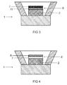
- FIG. 3 shows an inventive embodiment of an LED 1, in which the film of ceramic or glass ceramic, which acts as a substrate 7, is sintered only briefly at low temperature. That's why she has many open pores. The glass matrix fills these pores out. By using an excess of glass, a thin layer 11 of glass also remains on the surface of the substrate. The phosphor is dispersed in the glass matrix both in the region of the thin layer 11 and in the region of the pores.
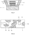
- FIG. 8 shows FIG. 8 in detail without layer 11. There, the substrate 7 is shown with open pores 12. Into the pores, the glass matrix 10 is sucked in. Phosphor grains 13 are dispersed in the glass matrix.
- FIG. 4 schematically shows a non-inventive embodiment of an LED 1, in which the substrate 7 via a conventional adhesive layer (not separately shown) with the chip 2 type InGaN blue (peak at about 440 to 450 nm) is connected.
- the glass matrix 8 with the phosphor immersed therein is fastened on the side of the substrate 7 facing away from the chip.
- the conventional adhesive layer is usually silicone. It is used when relatively temperature sensitive chips are used.
- an adhesive layer of high refractive index glass is more advantageous. Because then the heat dissipation is better and the light extraction is higher. This increases efficiency.
- an independent technical solution is to use the high refractive glasses presented alone as an adhesive (especially in the direction of the chip or the housing), that is without embedding a phosphor.
- the phosphor alone is introduced into the ceramic substrate or several phosphor-containing Ceramic substrates can be bonded together via such an adhesive.
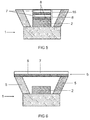
- FIG. 5 schematically shows a non-inventive embodiment of an LED 1, in which a double structure of the conversion element 6, 16 is used.
- a first layer 8 with glass matrix and first phosphor preferably a red-emitting phosphor such as a nitridosilicate M2Si5N8: Eu
- first substrate 7 which in turn is connected to a second glass matrix 8
- second Substrate 7 is connected.
- the glass matrix 8 acts in each case as an adhesive.
- Particularly suitable phosphors are YAG: Ce or another garnet, orthosilicate or sione, nitridosilicate, sialon, calsine, etc.
- FIG. 6 shows a non-inventive embodiment of an LED 1, which is a conversion element 6 spaced upstream of the chip 2.
- the side wall 5 of the housing which acts as a reflector, for example by the inner wall is suitably coated, at its end the conversion element 6.
- the glass matrix 8 acts as an adhesive to the side wall, the substrate 7 is remote from the chip.
- the conversion element 6 closes the opening of the reflector.
- FIG. 7 shows a non-inventive embodiment for an LED 1, in which a conversion element 6 sandwiched. It uses a UV emitting chip 2 with about 380 nm peak wavelength.
- a first glass matrix 8 adheres directly to the chip 2, in which a first phosphor is dispersed, for example a red, UV-excitable phosphor like the Calsin CaAlSiN3: Eu.
- a substrate 7 made of a mixture of YAG and YAG: Ce, which emits yellow.
- An additional blue emitting phosphor, such as BAM: Eu is dispersed in a second glass matrix 8, which is externally mounted in front of the substrate 7.
- Non-inventive embodiments of a converter for the conversion of the UV component into blue light are z.
- a non-inventive embodiment of a converter for the conversion of the UV component in yellow light is z.
- x and y are each in the range of 0.1 to 0.01.
- Non-inventive embodiments of a converter for the conversion of the UV component in red light are z.
Landscapes
- Engineering & Computer Science (AREA)
- Microelectronics & Electronic Packaging (AREA)
- Manufacturing & Machinery (AREA)
- Computer Hardware Design (AREA)
- Power Engineering (AREA)
- Led Device Packages (AREA)
Applications Claiming Priority (2)
| Application Number | Priority Date | Filing Date | Title |
|---|---|---|---|
| DE102010042217A DE102010042217A1 (de) | 2010-10-08 | 2010-10-08 | Optoelektronisches Halbleiterbauelement und Verfahren zu seiner Herstellung |
| PCT/EP2011/067381 WO2012045772A1 (de) | 2010-10-08 | 2011-10-05 | Optoelektronisches halbleiterbauelement und verfahren zu seiner herstellung |
Publications (2)
| Publication Number | Publication Date |
|---|---|
| EP2625724A1 EP2625724A1 (de) | 2013-08-14 |
| EP2625724B1 true EP2625724B1 (de) | 2016-11-30 |
Family
ID=44764153
Family Applications (1)
| Application Number | Title | Priority Date | Filing Date |
|---|---|---|---|
| EP11766989.5A Active EP2625724B1 (de) | 2010-10-08 | 2011-10-05 | Optoelektronisches halbleiterbauelement und verfahren zu seiner herstellung |
Country Status (7)
| Country | Link |
|---|---|
| US (1) | US20130207151A1 (ja) |
| EP (1) | EP2625724B1 (ja) |
| JP (2) | JP2013539238A (ja) |
| KR (1) | KR101845840B1 (ja) |
| CN (1) | CN103155187B (ja) |
| DE (1) | DE102010042217A1 (ja) |
| WO (1) | WO2012045772A1 (ja) |
Families Citing this family (21)
| Publication number | Priority date | Publication date | Assignee | Title |
|---|---|---|---|---|
| JP5649202B2 (ja) * | 2012-04-24 | 2015-01-07 | 株式会社光波 | 蛍光体及びその製造方法、並びに発光装置 |
| DE102012210083A1 (de) * | 2012-06-15 | 2013-12-19 | Osram Gmbh | Optoelektronisches halbleiterbauelement |
| KR101964418B1 (ko) * | 2012-07-02 | 2019-04-01 | 엘지이노텍 주식회사 | 형광체 조성물 및 이를 포함하는 조명 장치 |
| DE102012107290A1 (de) | 2012-08-08 | 2014-02-13 | Osram Opto Semiconductors Gmbh | Optoelektronisches Halbleiterbauteil, Konversionsmittelplättchen und Verfahren zur Herstellung eines Konversionsmittelplättchens |
| DE102012107797A1 (de) * | 2012-08-23 | 2014-02-27 | Osram Opto Semiconductors Gmbh | Verfahren zur Herstellung eines Licht emittierenden Halbleiterbauelements und Licht emittierendes Halbleiterbauelement |
| DE102012108160A1 (de) * | 2012-09-03 | 2014-03-06 | Osram Opto Semiconductors Gmbh | Optoelektronisches Halbleiterbauelement und Verfahren zur Herstellung eines optoelektronischen Halbleiterbauelements |
| DE102012110668A1 (de) | 2012-11-07 | 2014-05-08 | Osram Opto Semiconductors Gmbh | Konvertermaterial, Verfahren zur Herstellung eines Konvertermaterials und optoelektronisches Bauelement |
| DE102012220980A1 (de) * | 2012-11-16 | 2014-05-22 | Osram Gmbh | Optoelektronisches halbleiterbauelement |
| KR102180388B1 (ko) * | 2013-07-08 | 2020-11-19 | 루미리즈 홀딩 비.브이. | 파장 변환 반도체 발광 디바이스 |
| CN103489857B (zh) * | 2013-09-06 | 2017-06-06 | 中山市天健照明电器有限公司 | 一种白光led发光装置 |
| CN105874617A (zh) * | 2014-01-07 | 2016-08-17 | 皇家飞利浦有限公司 | 具有磷光体转换器的无胶发光器件 |
| JP2015142046A (ja) * | 2014-01-29 | 2015-08-03 | シャープ株式会社 | 波長変換部材、発光装置、および波長変換部材の製造方法 |
| JP6252982B2 (ja) * | 2014-02-06 | 2017-12-27 | 日本電気硝子株式会社 | ガラス部材及びその製造方法 |
| JP6575923B2 (ja) * | 2014-09-26 | 2019-09-18 | 日本電気硝子株式会社 | 波長変換部材及びそれを用いた発光装置 |
| JP2017188592A (ja) | 2016-04-06 | 2017-10-12 | 日亜化学工業株式会社 | 発光装置 |
| DE102017104134A1 (de) * | 2017-02-28 | 2018-08-30 | Osram Gmbh | Optoelektronisches Bauelement und Verfahren zur Herstellung eines optoelektronischen Bauelements |
| CN110612001B (zh) * | 2018-06-14 | 2023-06-30 | 因特瓦克公司 | 多色介电涂层及uv喷墨打印 |
| US10475968B1 (en) * | 2018-07-19 | 2019-11-12 | Osram Opto Semiconductors Gmbh | Optoelectronic component and a method for producing an optoelectronic component |
| EP3608959B1 (en) * | 2018-08-06 | 2023-11-15 | Nichia Corporation | Light emitting device and method for manufacturing same |
| JP6963720B2 (ja) * | 2018-08-30 | 2021-11-10 | 日亜化学工業株式会社 | 発光装置 |
| WO2023072867A1 (en) * | 2021-10-29 | 2023-05-04 | Ams-Osram International Gmbh | Optoelectronic semiconductor chip, optoelectronic component and method for producing an optoelectronic semiconductor chip |
Family Cites Families (18)
| Publication number | Priority date | Publication date | Assignee | Title |
|---|---|---|---|---|
| TW383508B (en) | 1996-07-29 | 2000-03-01 | Nichia Kagaku Kogyo Kk | Light emitting device and display |
| US20030102473A1 (en) * | 2001-08-15 | 2003-06-05 | Motorola, Inc. | Structure and method for fabricating semiconductor structures and devices utilizing the formation of a compliant substrate |
| DE102004019802B4 (de) * | 2004-03-11 | 2007-01-25 | Schott Ag | Verwendung eines lumineszierenden Glases als Konversionsmedium zur Erzeugung von weißem Licht |
| US7553683B2 (en) * | 2004-06-09 | 2009-06-30 | Philips Lumiled Lighting Co., Llc | Method of forming pre-fabricated wavelength converting elements for semiconductor light emitting devices |
| US8324641B2 (en) * | 2007-06-29 | 2012-12-04 | Ledengin, Inc. | Matrix material including an embedded dispersion of beads for a light-emitting device |
| US8134292B2 (en) * | 2004-10-29 | 2012-03-13 | Ledengin, Inc. | Light emitting device with a thermal insulating and refractive index matching material |
| DE102005023134A1 (de) * | 2005-05-19 | 2006-11-23 | Patent-Treuhand-Gesellschaft für elektrische Glühlampen mbH | Lumineszenzkonversions-LED |
| JP4765525B2 (ja) * | 2005-06-29 | 2011-09-07 | 日本電気硝子株式会社 | 発光色変換部材 |
| JP2007048864A (ja) * | 2005-08-09 | 2007-02-22 | Nippon Electric Glass Co Ltd | 蛍光体複合材料 |
| JP2007191702A (ja) * | 2005-12-22 | 2007-08-02 | Nippon Electric Glass Co Ltd | 発光色変換材料 |
| JP4969119B2 (ja) * | 2006-03-20 | 2012-07-04 | 日本碍子株式会社 | 発光ダイオード装置 |
| US8481977B2 (en) * | 2006-03-24 | 2013-07-09 | Goldeneye, Inc. | LED light source with thermally conductive luminescent matrix |
| JP4978886B2 (ja) * | 2006-06-14 | 2012-07-18 | 日本電気硝子株式会社 | 蛍光体複合材料及び蛍光体複合部材 |
| US20080121911A1 (en) * | 2006-11-28 | 2008-05-29 | Cree, Inc. | Optical preforms for solid state light emitting dice, and methods and systems for fabricating and assembling same |
| DE102007057812A1 (de) * | 2007-11-30 | 2009-06-25 | Schott Ag | Lichtemittierende Vorrichtung und Verfahren zu deren Herstellung sowie Lichtkonverter und dessen Verwendung |
| US20090200561A1 (en) * | 2008-01-30 | 2009-08-13 | Burrell Anthony K | Composite phosphors based on coating porous substrates |
| DE102008021666A1 (de) * | 2008-04-30 | 2009-11-05 | Ledon Lighting Jennersdorf Gmbh | Lichtemittierende Vorrichtung und Verfahren zur Herstellung einer lichtemittierenden Vorrichtung |
| DE102010009456A1 (de) | 2010-02-26 | 2011-09-01 | Osram Opto Semiconductors Gmbh | Strahlungsemittierendes Bauelement mit einem Halbleiterchip und einem Konversionselement und Verfahren zu dessen Herstellung |
-
2010
- 2010-10-08 DE DE102010042217A patent/DE102010042217A1/de not_active Withdrawn
-
2011
- 2011-10-05 CN CN201180048562.8A patent/CN103155187B/zh active Active
- 2011-10-05 JP JP2013532182A patent/JP2013539238A/ja active Pending
- 2011-10-05 WO PCT/EP2011/067381 patent/WO2012045772A1/de active Application Filing
- 2011-10-05 EP EP11766989.5A patent/EP2625724B1/de active Active
- 2011-10-05 KR KR1020137011927A patent/KR101845840B1/ko active IP Right Grant
- 2011-10-05 US US13/878,249 patent/US20130207151A1/en not_active Abandoned
-
2015
- 2015-03-10 JP JP2015047523A patent/JP6009020B2/ja active Active
Also Published As
| Publication number | Publication date |
|---|---|
| KR20130114671A (ko) | 2013-10-17 |
| JP2015109483A (ja) | 2015-06-11 |
| CN103155187A (zh) | 2013-06-12 |
| KR101845840B1 (ko) | 2018-04-06 |
| EP2625724A1 (de) | 2013-08-14 |
| WO2012045772A1 (de) | 2012-04-12 |
| JP2013539238A (ja) | 2013-10-17 |
| DE102010042217A1 (de) | 2012-04-12 |
| US20130207151A1 (en) | 2013-08-15 |
| CN103155187B (zh) | 2016-12-07 |
| JP6009020B2 (ja) | 2016-10-19 |
Similar Documents
| Publication | Publication Date | Title |
|---|---|---|
| EP2625724B1 (de) | Optoelektronisches halbleiterbauelement und verfahren zu seiner herstellung | |
| DE112013002930B4 (de) | Optoelektronisches Halbleiterbauelement | |
| DE10349038B4 (de) | Lichtquelle mit einer LED und einem Lumineszenzkonversionskörper und Verfahren zum Herstellen des Lumineszenzkonversionskörpers | |
| DE112015001180T5 (de) | Wellenlängenkonversionselement, lichtemittierende Halbleiterkomponente, die ein Wellenlängenkonversionselement umfasst, Verfahren zum Herstellen eines Wellenlängenkonversionselements und Verfahren zum Herstellen einer lichtemittierenden Halbleiterkomponente, die ein Wellenlängenkonversionselement umfasst | |
| WO2011104364A1 (de) | Strahlungsemittierendes bauelement mit einem halbleiterchip und einem konversionselement und verfahren zu dessen herstellung | |
| DE112014004933T5 (de) | Wellenlängenumwandlungselement, Verfahren zur Herstellung und Licht emittierender Halbleiterbauteil, welcher dasselbe aufweist | |
| DE112014005897B4 (de) | Konversionselement, Bauelement und Verfahren zur Herstellung eines Bauelements | |
| DE102013207308B4 (de) | Verfahren zum Herstellen einer optoelektronischen Baugruppe und optoelektronische Baugruppe | |
| DE102012220980A1 (de) | Optoelektronisches halbleiterbauelement | |
| WO2019179769A1 (de) | Optoelektronisches bauelement und verfahren zur herstellung eines optoelektronischen bauelements | |
| DE102011078689A1 (de) | Verfahren zur Herstellung eines Konversionselements und Konversionselement | |
| DE102013212247B4 (de) | Optoelektronisches Bauelement und Verfahren zu seiner Herstellung | |
| DE102018106655A1 (de) | Licht-emittierende Vorrichtung und Verfahren zu ihrer Herstellung | |
| DE112020005122T5 (de) | Leuchtstoffplatte, lichtemittierende Vorrichtung und Verfahren zur Herstellung einer Leuchtstoffplatte | |
| DE102009010468A1 (de) | Strahlungsemittierendes Funktionsmaterial mit darauf angeordneten Lichtkonversionsstoff-Partikeln, Verfahren zu dessen Herstellung und optoelektronisches Bauelement, enthaltend ein derartiges Funktionsmaterial | |
| DE102005012953A1 (de) | Verfahren zur Herstellung eines optoelektronischen Bauelements | |
| WO2011009737A1 (de) | Leuchtdiode mit einer keramischen abdeckung und verfahren zur herstellung dieser leuchtdiode | |
| DE102022132657A1 (de) | Lichtemittierende vorrichtung | |
| DE112019003634T5 (de) | Optoelektronisches bauelement und das verfahren zur herstellung eines optoeklektronischen bauelements | |
| DE102013105533A1 (de) | Anorganisches optisches Element und Verfahren zur Herstellung eines anorganischen optischen Elements | |
| DE102018128536A1 (de) | Konversionselemente umfassend eine Infiltrationsmatrix | |
| WO2012152652A1 (de) | Konversionselement für leuchtdioden und herstellungsverfahren | |
| WO2015107211A1 (de) | Verfahren zur herstellung einer lateral strukturierten phosphorschicht und optoelektronisches halbleiterbauteil mit einer solchen phosphorschicht | |
| DE102018130526B4 (de) | Bauteil mit einem reflektierenden Gehäuse und Herstellungsverfahren für ein solches Bauteil | |
| DE102018126494A1 (de) | Optoelektronisches bauteil, verfahren zur herstellung eines optoelektronischen bauteils und beleuchtungsvorrichtung |
Legal Events
| Date | Code | Title | Description |
|---|---|---|---|
| PUAI | Public reference made under article 153(3) epc to a published international application that has entered the european phase |
Free format text: ORIGINAL CODE: 0009012 |
|
| 17P | Request for examination filed |
Effective date: 20130508 |
|
| AK | Designated contracting states |
Kind code of ref document: A1 Designated state(s): AL AT BE BG CH CY CZ DE DK EE ES FI FR GB GR HR HU IE IS IT LI LT LU LV MC MK MT NL NO PL PT RO RS SE SI SK SM TR |
|
| DAX | Request for extension of the european patent (deleted) | ||
| GRAP | Despatch of communication of intention to grant a patent |
Free format text: ORIGINAL CODE: EPIDOSNIGR1 |
|
| INTG | Intention to grant announced |
Effective date: 20160624 |
|
| RIC1 | Information provided on ipc code assigned before grant |
Ipc: H01L 33/50 20100101AFI20160614BHEP Ipc: H01L 33/64 20100101ALN20160614BHEP |
|
| GRAS | Grant fee paid |
Free format text: ORIGINAL CODE: EPIDOSNIGR3 |
|
| GRAA | (expected) grant |
Free format text: ORIGINAL CODE: 0009210 |
|
| AK | Designated contracting states |
Kind code of ref document: B1 Designated state(s): AL AT BE BG CH CY CZ DE DK EE ES FI FR GB GR HR HU IE IS IT LI LT LU LV MC MK MT NL NO PL PT RO RS SE SI SK SM TR |
|
| REG | Reference to a national code |
Ref country code: CH Ref legal event code: EP Ref country code: GB Ref legal event code: FG4D Free format text: NOT ENGLISH |
|
| REG | Reference to a national code |
Ref country code: AT Ref legal event code: REF Ref document number: 850551 Country of ref document: AT Kind code of ref document: T Effective date: 20161215 |
|
| REG | Reference to a national code |
Ref country code: IE Ref legal event code: FG4D Free format text: LANGUAGE OF EP DOCUMENT: GERMAN |
|
| RIN2 | Information on inventor provided after grant (corrected) |
Inventor name: KOTTER, STEFAN Inventor name: EBERHARDT, ANGELA Inventor name: SCHMIDT, REINHOLD Inventor name: HUETTINGER, ROLAND |
|
| REG | Reference to a national code |
Ref country code: DE Ref legal event code: R096 Ref document number: 502011011259 Country of ref document: DE |
|
| PG25 | Lapsed in a contracting state [announced via postgrant information from national office to epo] |
Ref country code: LV Free format text: LAPSE BECAUSE OF FAILURE TO SUBMIT A TRANSLATION OF THE DESCRIPTION OR TO PAY THE FEE WITHIN THE PRESCRIBED TIME-LIMIT Effective date: 20161130 |
|
| REG | Reference to a national code |
Ref country code: LT Ref legal event code: MG4D |
|
| PG25 | Lapsed in a contracting state [announced via postgrant information from national office to epo] |
Ref country code: GR Free format text: LAPSE BECAUSE OF FAILURE TO SUBMIT A TRANSLATION OF THE DESCRIPTION OR TO PAY THE FEE WITHIN THE PRESCRIBED TIME-LIMIT Effective date: 20170301 Ref country code: SE Free format text: LAPSE BECAUSE OF FAILURE TO SUBMIT A TRANSLATION OF THE DESCRIPTION OR TO PAY THE FEE WITHIN THE PRESCRIBED TIME-LIMIT Effective date: 20161130 Ref country code: NO Free format text: LAPSE BECAUSE OF FAILURE TO SUBMIT A TRANSLATION OF THE DESCRIPTION OR TO PAY THE FEE WITHIN THE PRESCRIBED TIME-LIMIT Effective date: 20170228 Ref country code: LT Free format text: LAPSE BECAUSE OF FAILURE TO SUBMIT A TRANSLATION OF THE DESCRIPTION OR TO PAY THE FEE WITHIN THE PRESCRIBED TIME-LIMIT Effective date: 20161130 |
|
| PG25 | Lapsed in a contracting state [announced via postgrant information from national office to epo] |
Ref country code: PL Free format text: LAPSE BECAUSE OF FAILURE TO SUBMIT A TRANSLATION OF THE DESCRIPTION OR TO PAY THE FEE WITHIN THE PRESCRIBED TIME-LIMIT Effective date: 20161130 Ref country code: ES Free format text: LAPSE BECAUSE OF FAILURE TO SUBMIT A TRANSLATION OF THE DESCRIPTION OR TO PAY THE FEE WITHIN THE PRESCRIBED TIME-LIMIT Effective date: 20161130 Ref country code: PT Free format text: LAPSE BECAUSE OF FAILURE TO SUBMIT A TRANSLATION OF THE DESCRIPTION OR TO PAY THE FEE WITHIN THE PRESCRIBED TIME-LIMIT Effective date: 20170330 Ref country code: FI Free format text: LAPSE BECAUSE OF FAILURE TO SUBMIT A TRANSLATION OF THE DESCRIPTION OR TO PAY THE FEE WITHIN THE PRESCRIBED TIME-LIMIT Effective date: 20161130 Ref country code: HR Free format text: LAPSE BECAUSE OF FAILURE TO SUBMIT A TRANSLATION OF THE DESCRIPTION OR TO PAY THE FEE WITHIN THE PRESCRIBED TIME-LIMIT Effective date: 20161130 Ref country code: RS Free format text: LAPSE BECAUSE OF FAILURE TO SUBMIT A TRANSLATION OF THE DESCRIPTION OR TO PAY THE FEE WITHIN THE PRESCRIBED TIME-LIMIT Effective date: 20161130 |
|
| PG25 | Lapsed in a contracting state [announced via postgrant information from national office to epo] |
Ref country code: NL Free format text: LAPSE BECAUSE OF FAILURE TO SUBMIT A TRANSLATION OF THE DESCRIPTION OR TO PAY THE FEE WITHIN THE PRESCRIBED TIME-LIMIT Effective date: 20161130 |
|
| PG25 | Lapsed in a contracting state [announced via postgrant information from national office to epo] |
Ref country code: CZ Free format text: LAPSE BECAUSE OF FAILURE TO SUBMIT A TRANSLATION OF THE DESCRIPTION OR TO PAY THE FEE WITHIN THE PRESCRIBED TIME-LIMIT Effective date: 20161130 Ref country code: SK Free format text: LAPSE BECAUSE OF FAILURE TO SUBMIT A TRANSLATION OF THE DESCRIPTION OR TO PAY THE FEE WITHIN THE PRESCRIBED TIME-LIMIT Effective date: 20161130 Ref country code: EE Free format text: LAPSE BECAUSE OF FAILURE TO SUBMIT A TRANSLATION OF THE DESCRIPTION OR TO PAY THE FEE WITHIN THE PRESCRIBED TIME-LIMIT Effective date: 20161130 Ref country code: DK Free format text: LAPSE BECAUSE OF FAILURE TO SUBMIT A TRANSLATION OF THE DESCRIPTION OR TO PAY THE FEE WITHIN THE PRESCRIBED TIME-LIMIT Effective date: 20161130 Ref country code: RO Free format text: LAPSE BECAUSE OF FAILURE TO SUBMIT A TRANSLATION OF THE DESCRIPTION OR TO PAY THE FEE WITHIN THE PRESCRIBED TIME-LIMIT Effective date: 20161130 |
|
| PG25 | Lapsed in a contracting state [announced via postgrant information from national office to epo] |
Ref country code: IT Free format text: LAPSE BECAUSE OF FAILURE TO SUBMIT A TRANSLATION OF THE DESCRIPTION OR TO PAY THE FEE WITHIN THE PRESCRIBED TIME-LIMIT Effective date: 20161130 Ref country code: BG Free format text: LAPSE BECAUSE OF FAILURE TO SUBMIT A TRANSLATION OF THE DESCRIPTION OR TO PAY THE FEE WITHIN THE PRESCRIBED TIME-LIMIT Effective date: 20170228 Ref country code: SM Free format text: LAPSE BECAUSE OF FAILURE TO SUBMIT A TRANSLATION OF THE DESCRIPTION OR TO PAY THE FEE WITHIN THE PRESCRIBED TIME-LIMIT Effective date: 20161130 |
|
| REG | Reference to a national code |
Ref country code: DE Ref legal event code: R097 Ref document number: 502011011259 Country of ref document: DE |
|
| PLBE | No opposition filed within time limit |
Free format text: ORIGINAL CODE: 0009261 |
|
| 26N | No opposition filed |
Effective date: 20170831 |
|
| PG25 | Lapsed in a contracting state [announced via postgrant information from national office to epo] |
Ref country code: SI Free format text: LAPSE BECAUSE OF FAILURE TO SUBMIT A TRANSLATION OF THE DESCRIPTION OR TO PAY THE FEE WITHIN THE PRESCRIBED TIME-LIMIT Effective date: 20161130 |
|
| REG | Reference to a national code |
Ref country code: DE Ref legal event code: R081 Ref document number: 502011011259 Country of ref document: DE Owner name: OSRAM OPTO SEMICONDUCTORS GMBH, DE Free format text: FORMER OWNER: OSRAM GMBH, 80807 MUENCHEN, DE |
|
| PLAA | Information modified related to event that no opposition was filed |
Free format text: ORIGINAL CODE: 0009299DELT |
|
| PLBE | No opposition filed within time limit |
Free format text: ORIGINAL CODE: 0009261 |
|
| STAA | Information on the status of an ep patent application or granted ep patent |
Free format text: STATUS: NO OPPOSITION FILED WITHIN TIME LIMIT |
|
| R26N | No opposition filed (corrected) |
Effective date: 20170831 |
|
| RAP2 | Party data changed (patent owner data changed or rights of a patent transferred) |
Owner name: OSRAM OPTO SEMICONDUCTORS GMBH |
|
| PG25 | Lapsed in a contracting state [announced via postgrant information from national office to epo] |
Ref country code: MC Free format text: LAPSE BECAUSE OF FAILURE TO SUBMIT A TRANSLATION OF THE DESCRIPTION OR TO PAY THE FEE WITHIN THE PRESCRIBED TIME-LIMIT Effective date: 20161130 |
|
| REG | Reference to a national code |
Ref country code: CH Ref legal event code: PL |
|
| GBPC | Gb: european patent ceased through non-payment of renewal fee |
Effective date: 20171005 |
|
| REG | Reference to a national code |
Ref country code: IE Ref legal event code: MM4A |
|
| REG | Reference to a national code |
Ref country code: FR Ref legal event code: ST Effective date: 20180629 |
|
| PG25 | Lapsed in a contracting state [announced via postgrant information from national office to epo] |
Ref country code: CH Free format text: LAPSE BECAUSE OF NON-PAYMENT OF DUE FEES Effective date: 20171031 Ref country code: GB Free format text: LAPSE BECAUSE OF NON-PAYMENT OF DUE FEES Effective date: 20171005 Ref country code: LU Free format text: LAPSE BECAUSE OF NON-PAYMENT OF DUE FEES Effective date: 20171005 Ref country code: LI Free format text: LAPSE BECAUSE OF NON-PAYMENT OF DUE FEES Effective date: 20171031 |
|
| REG | Reference to a national code |
Ref country code: BE Ref legal event code: MM Effective date: 20171031 |
|
| PG25 | Lapsed in a contracting state [announced via postgrant information from national office to epo] |
Ref country code: BE Free format text: LAPSE BECAUSE OF NON-PAYMENT OF DUE FEES Effective date: 20171031 Ref country code: FR Free format text: LAPSE BECAUSE OF NON-PAYMENT OF DUE FEES Effective date: 20171031 |
|
| PG25 | Lapsed in a contracting state [announced via postgrant information from national office to epo] |
Ref country code: MT Free format text: LAPSE BECAUSE OF FAILURE TO SUBMIT A TRANSLATION OF THE DESCRIPTION OR TO PAY THE FEE WITHIN THE PRESCRIBED TIME-LIMIT Effective date: 20161130 |
|
| PG25 | Lapsed in a contracting state [announced via postgrant information from national office to epo] |
Ref country code: IE Free format text: LAPSE BECAUSE OF NON-PAYMENT OF DUE FEES Effective date: 20171005 |
|
| REG | Reference to a national code |
Ref country code: AT Ref legal event code: MM01 Ref document number: 850551 Country of ref document: AT Kind code of ref document: T Effective date: 20171005 |
|
| PG25 | Lapsed in a contracting state [announced via postgrant information from national office to epo] |
Ref country code: AT Free format text: LAPSE BECAUSE OF NON-PAYMENT OF DUE FEES Effective date: 20171005 |
|
| PG25 | Lapsed in a contracting state [announced via postgrant information from national office to epo] |
Ref country code: HU Free format text: LAPSE BECAUSE OF FAILURE TO SUBMIT A TRANSLATION OF THE DESCRIPTION OR TO PAY THE FEE WITHIN THE PRESCRIBED TIME-LIMIT; INVALID AB INITIO Effective date: 20111005 |
|
| PG25 | Lapsed in a contracting state [announced via postgrant information from national office to epo] |
Ref country code: CY Free format text: LAPSE BECAUSE OF NON-PAYMENT OF DUE FEES Effective date: 20161130 |
|
| PG25 | Lapsed in a contracting state [announced via postgrant information from national office to epo] |
Ref country code: MK Free format text: LAPSE BECAUSE OF FAILURE TO SUBMIT A TRANSLATION OF THE DESCRIPTION OR TO PAY THE FEE WITHIN THE PRESCRIBED TIME-LIMIT Effective date: 20161130 |
|
| PG25 | Lapsed in a contracting state [announced via postgrant information from national office to epo] |
Ref country code: TR Free format text: LAPSE BECAUSE OF FAILURE TO SUBMIT A TRANSLATION OF THE DESCRIPTION OR TO PAY THE FEE WITHIN THE PRESCRIBED TIME-LIMIT Effective date: 20161130 |
|
| PG25 | Lapsed in a contracting state [announced via postgrant information from national office to epo] |
Ref country code: AL Free format text: LAPSE BECAUSE OF FAILURE TO SUBMIT A TRANSLATION OF THE DESCRIPTION OR TO PAY THE FEE WITHIN THE PRESCRIBED TIME-LIMIT Effective date: 20161130 Ref country code: IS Free format text: LAPSE BECAUSE OF FAILURE TO SUBMIT A TRANSLATION OF THE DESCRIPTION OR TO PAY THE FEE WITHIN THE PRESCRIBED TIME-LIMIT Effective date: 20170330 |
|
| P01 | Opt-out of the competence of the unified patent court (upc) registered |
Effective date: 20230825 |
|
| PGFP | Annual fee paid to national office [announced via postgrant information from national office to epo] |
Ref country code: DE Payment date: 20231020 Year of fee payment: 13 |