EP2624684B1 - Vorrichtung und verfahren zur reinigung einer stützstrukutr für geflügelkäfige - Google Patents
Vorrichtung und verfahren zur reinigung einer stützstrukutr für geflügelkäfige Download PDFInfo
- Publication number
- EP2624684B1 EP2624684B1 EP11767818.5A EP11767818A EP2624684B1 EP 2624684 B1 EP2624684 B1 EP 2624684B1 EP 11767818 A EP11767818 A EP 11767818A EP 2624684 B1 EP2624684 B1 EP 2624684B1
- Authority
- EP
- European Patent Office
- Prior art keywords
- support structure
- liquid bath
- liquid
- underside
- poultry holders
- Prior art date
- Legal status (The legal status is an assumption and is not a legal conclusion. Google has not performed a legal analysis and makes no representation as to the accuracy of the status listed.)
- Active
Links
Images


Classifications
-
- A—HUMAN NECESSITIES
- A01—AGRICULTURE; FORESTRY; ANIMAL HUSBANDRY; HUNTING; TRAPPING; FISHING
- A01K—ANIMAL HUSBANDRY; AVICULTURE; APICULTURE; PISCICULTURE; FISHING; REARING OR BREEDING ANIMALS, NOT OTHERWISE PROVIDED FOR; NEW BREEDS OF ANIMALS
- A01K45/00—Other aviculture appliances, e.g. devices for determining whether a bird is about to lay
- A01K45/005—Harvesting or transport of poultry
-
- B—PERFORMING OPERATIONS; TRANSPORTING
- B08—CLEANING
- B08B—CLEANING IN GENERAL; PREVENTION OF FOULING IN GENERAL
- B08B3/00—Cleaning by methods involving the use or presence of liquid or steam
- B08B3/04—Cleaning involving contact with liquid
- B08B3/041—Cleaning travelling work
-
- B—PERFORMING OPERATIONS; TRANSPORTING
- B08—CLEANING
- B08B—CLEANING IN GENERAL; PREVENTION OF FOULING IN GENERAL
- B08B3/00—Cleaning by methods involving the use or presence of liquid or steam
- B08B3/04—Cleaning involving contact with liquid
- B08B3/10—Cleaning involving contact with liquid with additional treatment of the liquid or of the object being cleaned, e.g. by heat, by electricity or by vibration
- B08B3/102—Cleaning involving contact with liquid with additional treatment of the liquid or of the object being cleaned, e.g. by heat, by electricity or by vibration with means for agitating the liquid
-
- B—PERFORMING OPERATIONS; TRANSPORTING
- B08—CLEANING
- B08B—CLEANING IN GENERAL; PREVENTION OF FOULING IN GENERAL
- B08B9/00—Cleaning hollow articles by methods or apparatus specially adapted thereto
- B08B9/08—Cleaning containers, e.g. tanks
- B08B9/0821—Handling or manipulating containers, e.g. moving or rotating containers in cleaning devices, conveying to or from cleaning devices
- B08B9/0826—Handling or manipulating containers, e.g. moving or rotating containers in cleaning devices, conveying to or from cleaning devices the containers being brought to the cleaning device
-
- B—PERFORMING OPERATIONS; TRANSPORTING
- B08—CLEANING
- B08B—CLEANING IN GENERAL; PREVENTION OF FOULING IN GENERAL
- B08B9/00—Cleaning hollow articles by methods or apparatus specially adapted thereto
- B08B9/08—Cleaning containers, e.g. tanks
- B08B9/0861—Cleaning crates, boxes or the like
Definitions
- the present invention relates to a device and a method for mechanized emptying of poultry holders and subsequent cleaning of a support structure of the emptied poultry holders on an underside only.
- the invention relates more particularly to cleaning only the underside of a support structure for poultry holders using a liquid following the mechanized opening and emptying of the poultry holders placed in the support structure.
- poultry holders are also referred to as pallets, crates, cages or containers.
- a plurality of such poultry holders can be combined in a shared support structure.
- Such a support structure generally consists of a steel frame in which a number of poultry holders are held in stacked (multilayer) manner and from which the poultry holders can be wholly or partially removed, and can thus for instance be embodied such that they can slide optionally fully into and out of the support structure, similarly to drawers in a chest of drawers.
- Another possibility is to integrate the containers with the support structure so that this latter comprises compartments provided with individually controllable closing means.
- the poultry holders become soiled with manure, feathers and other dirt.
- a current problem in the poultry farming sector is the rapid spread of diseases, for which, among other factors, the transport of poultry is an undesirable catalyst.
- the poultry containers can of course be thoroughly cleaned after they have been emptied.
- the support structures for the poultry holders are cleaned in less than disciplined and thorough manner, and when this does occasionally take place, the whole support structure is generally sprayed down.
- Complete spraying down and/or blowing clean of the support structure involves considerable work, requires a special cleaning area, requires a large amount of cleaning liquid and cannot be easily mechanized such that good cleaning results are achieved. Consistent and full cleaning of the support structures does not therefore represent a workable solution in practice.
- An additional, not insignificant object is to provide a technique which can be advantageously combined with the already existing automated processes for handling poultry holders.
- the invention provides for this purpose a device for mechanized emptying of poultry holders and subsequent cleaning of a support structure of the emptied poultry holders on an underside only, comprising: an unloading system for mechanized opening and emptying of poultry holders placed in the support structure; a liquid bath accessible to the support structure from the upper side; transport means provided with at least one displaceable support surface for supporting the support structure, which transport means lead from the unloading system to the liquid bath and subsequently through and out of the liquid bath such that only the underside of the support structure is immersed in the liquid bath and then removed again from the liquid bath by the transport means; and a liquid supply for carrying a cleaning liquid into the liquid bath.
- the insight of the inventors is that particularly the underside of the support structures forms a major source in the spread of diseases, bacteria, viruses and the like between different locations. It is possible here to envisage the spread of diseases, bacteria, viruses and the like between different locations such as: production locations (poultry houses for, among other activities, breeding and rearing), transport means (trucks) and processing locations (such as selection centres and slaughterhouses). Not only it is necessary here to envisage fouling present on the exterior of the underside of the support structures, but internal spaces on the underside of the support structure usually also become fouled essentially due to dirt penetrating therein. Such internal spaces can for instance include the inside of (tubular) profiles or the open spaces arranged in the support structure in order to for instance receive the prongs of a fork-lift truck.
- the insight of the present invention is that a less than obvious solution can be developed with which it is seemingly not possible to achieve particularly good cleaning results but which consists of also immersing only the underside of the support structure in a basin or bath in mechanized manner, this coupled in line with the mechanized unloading of the poultry holders, in order to thus disinfect at least a significant part of the base (also referred to as foot) of the support structure.
- the advantage of emptying the poultry holders coupled with cleaning the support structures on the underside only is that this makes it possible to rigidly couple the two processes to each other in relatively simple manner. This guarantees that the underside of each support structure is cleaned after the poultry holders held by the support structure have been emptied.
- Yet another advantage of immersing the underside of the support construction is that poorly accessible positions of the support structure for poultry holders can also come into contact with cleaning liquid, which produces a favourable cleaning result. It is for instance possible here to envisage the inside of profile parts of the support structure situated on the underside of the support constructions; the cleaning liquid will be able to flow like a "tidal wave" through such profiles, whereby dirt is carried away and the profile parts are also cleaned internally. It is also noted that it is possible to only partially immerse the support structure without poultry holders or the support structure with poultry holders received therein in the liquid bath, it being possible to choose one of these two options depending on the existing logistics with which poultry holders and support structures are processed.
- the only partial immersion can also be combined as desired with spraying (under pressure) the support structure for poultry holders.
- spraying under pressure
- the transport means and the measure that the transport means support the support construction it is possible to clean relatively voluminous and heavy support structures without the intervention, or with limited involvement, of operatives.
- the orientation of the support constructions during transport and cleaning is fully controlled (other than if for instance they are suspended from a conveyor).
- Another advantage of supported transport of the support constructions is that the conveyor is thus simple to load and unload. The chance of persons coming into contact with fouling on the support structures or with cleaning agent is also limited. Not only is a certain cleaning result thus obtained, this additional cleaning step moreover requires little time.
- the liquid bath accessible to the support structure from the upper side can optionally be closable and is preferably dimensioned such that, when the underside of a support structure is introduced and removed, no or only limited quantities of cleaning liquid leave the bath.
- the transport means are provided with a substantially horizontal first transport path for transporting the support structure from the unloading system to the liquid bath and, connecting thereto, an at least partially vertical second transport path which leads into the liquid bath for immersion of only the underside of the support structure for poultry holders in the liquid bath. It is further possible to provide the transport means with a third transport path leading through the liquid bath and connecting to the second transport path and having a substantially horizontal directional component and/or with a fourth transport path which connects to the third transport path, the fourth transport path comprising at least a vertical directional component and leading from a position in the liquid bath to a position above the liquid bath.
- the successive first and second transport paths make it possible to transport the support structures from the unloading system until their undersides are in the liquid bath.
- the only partial immersion of a support structure will normally also result in turbulence/ agitation of the cleaning liquid, which further supports the cleaning action of the liquid. It is also possible in this context to generate a liquid circulation and/or liquid turbulence in the liquid bath.
- the second transport path makes it possible to lower the support structure in mechanical manner only partially into the liquid bath from above and the fourth transport path makes it possible to lift the support structure in mechanical manner out of the liquid bath again.
- the advantage of the presence of the third transport path having a substantially horizontal directional component and lying in the liquid bath, for instance formed by a roller track or an endless conveyor belt, is that the underside of the support structures can be moved through the liquid bath with this transport path, which will result in a relative displacement between the liquid and the underside of the support structure, so effecting an improved cleaning.
- the third transport path can also function as buffer for support structures and the time for which the underside of a support structure remains in the cleaning liquid can hereby be increased.
- Examples of possible transport paths with a substantially horizontal directional component are a roller track or an endless belt.
- Such transport means supporting the support structures make it possible to process diverse types of support structure of a more or less complex form; the support structures do not require any specific means to enable handling by the device according to the present invention.
- a further advantage is that a supporting transport system can be combined relatively easily with transport systems usually present in slaughterhouses.
- the third transport path is situated wholly or partially in the liquid bath.
- the support structure for poultry holders is thus not only immersed in the cleaning liquid but also carried over a determined distance through it. It is particularly advantageous when profile parts for cleaning extend as much as possible in the direction of movement of the third transport path; the cleaning liquid will then be able to flow partially through possible open profile parts.
- a cleaning device wherein the support structure can be carried some distance through the liquid bath will however have to be larger than a device wherein only (vertical) immersion takes place, although it will normally also produce an improved cleaning result.
- Another advantage of such a throughfeed liquid bath is that successive support structures can be carried through the liquid bath in a continuous process. In a logistical process in which larger numbers of support structures have to be processed in line, this can be highly advantageous.
- the transport means can be provided with a fourth transport path with at least a vertical directional component for lifting the support structure for poultry holders out of the liquid bath.
- Taking the support structure out of the liquid bath can consist of movement through the second transport path in reverse direction to the feed (so a return movement such that the second and fourth transport paths coincide while a third transport path is absent), although it is also possible for removal of the support structure from the liquid bath to take place along another path (i.e. after the support structure has been displaced along a third transport path to a fourth transport path varying from the second transport path).
- the vertically displaceable support surface to be displaceable by a lifting mechanism. The support surface can thus move reciprocally as a lift.
- a vertically displaceable support surface engage on a lift guide.
- An example hereof is a roller guide engaging on a lifting mast.
- the support surface can here move reciprocally in the liquid bath.
- the support surface is preferably not a closed surface but rather an open (imaginary) flat supporting structure, whereby turbulences in the cleaning liquid also result in as much turbulence as possible where the cleaning liquid makes contact with the support structure.
- the transport means can be provided with a substantially vertically displaceable support surface for the support structures.
- This support surface can then be embodied such that it is displaceable between a position which connects to a conveyor feeding into (and optionally also discharging from) the support structures.
- the vertically displaceable support surface is also provided with transport means for substantially horizontal transport; the support structures can hereby also be displaced over the support surface in simple manner, this considerably simplifying loading and unloading of the support surface. Examples hereof are a roller track or conveyor belt integrated into the support surface.
- the carrying surface of the transport means is pivotable between a substantially horizontal position and an inclining position. It thus becomes possible to allow the support structure which has been cleaned on the underside to drain at least partially (optionally above the liquid bath, but desirably above the liquid bath).
- the support structure does not of course have to be held in a tilted position to allow draining thereof.
- placing the support structure in one or more tilting positions has the advantage that the cleaning liquid can thus be drained better; particularly if it is in internal spaces (such as for instance hollow profile parts). Draining and collecting the cleaning liquid has several advantages. Cleaning liquid is generally expensive and consumption thereof can be reduced by draining and collection.
- the cleaning liquid is moreover usually aggressive, so that it is desirable to prevent it being released at undesirable locations. It is also undesirable to allow the cleaning liquid to dry up, since this may result in deposition of residue. It is further of great importance to be able to accurately determine the weight of the support structure (optionally with poultry holders present therein), since this affects determination (calculation) of the prior content (live poultry) before the support structure with poultry holders was emptied (tare weight).
- the liquid supply can be provided with a water feed and a feed for disinfectant so that the composition (concentration) of the cleaning liquid in the liquid bath can be adapted to the conditions. It is further possible to provide a liquid buffer, with the advantage that sufficient cleaning liquid is thus available, which makes it possible to supply cleaning liquid quickly if this is desirable and whereby the level of the cleaning liquid can be adjusted when there is a need to do so, for instance in the presence of more or fewer support structures in the liquid bath or when there is a change in support structure type.
- the liquid supply can further also comprise at least one nozzle located in the liquid bath for causing turbulence in the cleaning liquid and/or spraying the immersed part of the support structure.
- the liquid supply can be provided with a sensor for detecting the height of a liquid level in the liquid bath, and with control means for maintaining a desired level of the liquid in the liquid bath.
- the quality of the cleaning liquid can also be monitored, and optionally automatically adjusted, by means of another type of sensor.
- the cleaning liquid can consist of water, optionally provided with one or more additional agents such as for instance a soap, a disinfectant, an antibacterial agent, any other cleaning agent or a combination thereof.
- additional agents such as for instance a soap, a disinfectant, an antibacterial agent, any other cleaning agent or a combination thereof.
- the cleaning action in the liquid bath can increase further when the liquid bath is provided with liquid turbulence-generating means. It is possible here to envisage a circulation pump, a driven rotor, moving and/or intermittent liquid jets and so on.
- the transport means can be provided with a blocking means for blocking the feed of support structures.
- the support structures for poultry holders can thus be fed in controlled and sequential manner to the liquid bath.
- the present invention also provides a method for mechanized emptying of poultry holders and subsequent cleaning of a support structure of the emptied poultry holders on an underside only, comprising the processing steps of: A) opening and emptying the poultry holders placed in a support structure in mechanized manner in an unloading system; B) displacing the support structure for poultry holders in supported and mechanized manner from the unloading system to a liquid bath; C) immersing the support structure for poultry holders only partially with the underside in supported manner in the liquid bath with cleaning agent in order to disinfect only the underside of the support structure; and D) removing the support structure for poultry holders, cleaned on the underside only, in supported manner from the liquid bath and allowing it to at least partially drain above the liquid bath.
- the support structure is placed in a tilting position during draining of the underside of the cleaned support structure as according to processing step D). Residual cleaning liquid will hereby be better removed. It is however also possible to envisage other measures for removing residual cleaning liquid from the support structure, such as for instance blowing and/or shaking. Less cleaning liquid will in this way be lost. It is possible in similar manner to prevent a possibly pre-cleaned support structure entering the cleaning liquid with a large amount of adhering flushing water. The advantage here is that dilution of the cleaning liquid can thus be reduced.
- the support structures for poultry holders can be pre-cleaned, for instance by blowing or spraying off coarse fouling or by pre-soaking the support structure for poultry holders, before the support structures for poultry holders are brought into contact with cleaning liquid in the liquid bath as according to processing step C).
- the cleaning liquid such that (optionally in combination with soap) its cleaning action is enhanced.
- FIG. 1 shows a schematic view of a device 1 according to the present invention.
- Device 1 is provided with an unloading system 2 where support structures 4 with poultry holders 5 filled with chickens 3 can be emptied.
- a support structure 4 filled with live chickens 3 is placed on a conveyor belt 7 by a fork-lift truck 6 and fed in mechanized manner to unloading system 2, where support structure 4 is tilted such that chickens 3 fall out of poultry holders 5, whereby the chickens enter a discharge system 8. From discharge system 8 the chickens 3 are for instance carried to a slaughter line (not shown here).
- Device 1 is further provided with a liquid bath 12 open at the top for receiving only the underside of support structure 4 for poultry holders 5.
- Support structure 4 can be carried into liquid bath 12 by a vertical conveyor 9.
- Connecting to liquid bath 12 is a liquid supply 13 with which cleaning liquid 14 is carried into liquid bath 12.
- Vertical conveyor 9 is adapted to respectively place support structure 4 with its underside in and remove it from liquid bath 12 as according to arrow P 1 .
- support structure 4 is supplied beforehand in horizontal direction as according to arrow P 2 by a horizontal conveyor 10 to vertical conveyor 9 along a first transport path - here in the form of an endless conveyor belt 10.
- Vertical conveyor 9 comprises a support surface 11 which is provided with openings and with which support structure 4 can be supported.
- Support surface 11 can be positioned so that it connects to horizontal conveyor 10. This makes it possible for a support structure 4 for poultry holders 5 to be pushed from horizontal conveyor 10 onto transport rollers 27 arranged in support surface 11.
- the horizontal conveyor 10 is connected via an arm 13 to a lift installation 25 which is shown highly schematic
- nozzles 15 Arranged in liquid bath 12 are nozzles 15 with which cleaning liquid 14 supplied under pressure by a pump 26 results in liquid flow preferably directed toward a support structure 4 placed only with its underside in liquid bath 12. Nozzles 15 are preferably situated for this purpose below liquid surface 16 such that they cause flow or turbulence of cleaning liquid 14 in liquid bath 12.
- the liquid level i.e. the height of liquid surface 16
- Pump 26 can here feed cleaning liquid 14 from a liquid buffer 19 when the liquid level drops below a determined minimum.
- Liquid bath 12 is further provided with a discharge 20 connecting to pump 26 for discharging cleaning liquid 14.
- Liquid bath 12 is preferably manufactured at least partially from stainless steel and is preferably further embodied such that fouling accumulating in bath 12, partially under the influence of flow possibly present in bath 12, collects for instance at one or more locations on the bottom where it can be easily removed.
- horizontal conveyor 10 is provided with a buffer catch 21 which is displaceable as according to arrow P 3 and which in an upward pivoted position prevents the passage of support structures 4.
- Support structure 4 can be removed directly from support surface 11 after cleaning, for instance using openings 22 intended for the prongs of fork-lift truck 6. It is on the other hand also possible to discharge the cleaned support structure 4 by means of a separate discharge belt (not shown in this figure) or with horizontal conveyor 10. Before discharge of support structure 4 it is desirable to first allow draining thereof above liquid bath 12; or, still better, by rotating support surface 11 through a limited angle of 0-30° around a rotation shaft 24 by means of a drive 23. The result is that support structure 4 comes to lie at an angle, with the consequence that at least some of the liquid still present in the underside of support structure 4 will be drained and will drip into liquid bath 12.
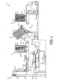
- FIG. 2 shows a schematic perspective view of a device 30 for cleaning the underside of support structures 31 for poultry holders 32.
- a support structure 31 is fed as according to arrow P 10 by a horizontal conveyor 33 along a first transport path in a manner such that continuous tubes 34 in the bottom segment of support structure 31 lie parallel to transport direction P 10 .
- An inclining conveyor 35 displaces support structures 31 downward with a vertical directional component along a second transport path such that they move into liquid bath 36 with the bottom part of support structure 31 below liquid surface 37 of cleaning liquid 38.
- a subsequent horizontal bottom conveyor 39 moves support structure 31 as according to arrow P 11 along a third transport path through liquid bath 36, and so also through cleaning liquid 38.
- a relative liquid flow of cleaning liquid 38 relative to the underside of support structure 31 will thus be created, this contributing toward a thorough cleaning.
- the support structures 31 for poultry holders 32 are carried obliquely upward again along a fourth transport path by an elevator conveyor 40 and finally discharged further as according to arrow P 12 by a horizontal discharge conveyor 41.
- a number of the control mechanisms as already described with reference to figure 1 can also form part of the device 30 as shown in figure 2 , although they are not shown here as such.
- FIG 3 shows a perspective view of a production line 50 for emptying and cleaning support structures 51 with poultry holders.
- a support structure 51 with poultry holders filled with livestock is fed as according to arrow P 5 and carried through an unloading system 52, from where the poultry is carried as according to arrow P 6 through a stunning tunnel 53 and then carried as according to arrow P 7 to the start of a slaughter line 54.
- the support structure 51 with poultry holders passes through a pre-washer 55.
- the thus pre-cleaned support structure 56 with poultry holders is then carried as according to arrow P 8 through a support structure cleaner 57, in which only the underside of the pre-cleaned support structure 56 is moved through a cleaning bath.
- the process which takes place in support structure cleaner 57 is not further shown in this figure, but a device as shown in figure 3 would for instance be highly suitable here.
- the finally cleaned support structure 58 leaves production line 50 as according to arrow P 9 .
Landscapes
- Life Sciences & Earth Sciences (AREA)
- Environmental Sciences (AREA)
- Engineering & Computer Science (AREA)
- Mechanical Engineering (AREA)
- Birds (AREA)
- Animal Husbandry (AREA)
- Biodiversity & Conservation Biology (AREA)
- Housing For Livestock And Birds (AREA)
- Processing Of Meat And Fish (AREA)
- Cleaning In General (AREA)
Claims (16)
- Vorrichtung zum mechanischen Entleeren von Geflügelkäfigen und zum nachfolgenden Reinigen einer Stützstruktur der entleerten Geflügelkäfige lediglich auf einer Unterseite, wobei die Vorrichtung Folgendes umfasst:- ein Entladesystem zum mechanischen Öffnen und Entleeren von in der Stützstruktur platzierten Geflügelkäfigen;- ein Flüssigkeitsbad, das der Stützstruktur von der Oberseite aus zugänglich ist;- Transportmittel, die mit mindestens einer verschiebbaren Trageoberfläche zur Abstützung der Stützstruktur ausgestattet sind, wobei die Transportmittel vom Entladesystem zum Flüssigkeitsbad und nachfolgend durch das Flüssigkeits-bad und aus diesem Bad heraus so verlaufen, dass lediglich die Unterseite der Stützstruktur in das Flüssigkeitsbad eintaucht und dann wieder durch die Transportmittel aus dem Flüssigkeits-bad entfernt wird; und- eine Flüssigkeitsversorgung, um eine Reinigungs-flüssigkeit in das Flüssigkeitsbad einzutragen.
- Vorrichtung nach Anspruch 1, dadurch gekennzeichnet, dass die Transportmittel mit einem im Wesentlichen horizontalen ersten Transportweg, um die Stützstruktur vom Entladesystem zum Flüssigkeitsbad zu transportieren, sowie, in Verbindung damit stehend, mit einem mindestens teilweise vertikalen zweiten Transportweg vorgesehen sind, der in das Flüssigkeitsbad hinein verläuft, um lediglich die Unterseite der Stützstruktur für Geflügelkäfige in das Flüssigkeitsbad einzutauchen.
- Vorrichtung nach Anspruch 2, dadurch gekennzeichnet, dass die Transportmittel mit einem dritten Transportweg vorgesehen sind, der durch das Flüssigkeitsbad verläuft, mit dem zweiten Transportweg verbunden ist und eine im Wesentlichen horizontale Richtungskomponente hat.
- Vorrichtung nach Anspruch 3, dadurch gekennzeichnet, dass die Transportmittel mit einem vierten Transportweg vorgesehen sind, der mit dem dritten Transportweg verbunden ist, wobei der vierte Transportweg mindestens eine vertikale Richtungskomponente umfasst und von einer Position im Flüssigkeitsbad zu einer Position oberhalb des Flüssigkeitsbades verläuft.
- Vorrichtung nach einem der vorstehend aufgeführten Ansprüche, dadurch gekennzeichnet, dass die Trageoberfläche der Transportmittel zwischen einer im Wesentlichen horizontalen Position und einer Neigungsposition schwenkbar ist.
- Vorrichtung nach einem der vorstehend aufgeführten Ansprüche, dadurch gekennzeichnet, dass die Flüssigkeitsversorgung eine Wasserzuspeisung und eine Desinfektionsmittelzuspeisung umfasst.
- Vorrichtung nach einem der vorstehend aufgeführten Ansprüche, dadurch gekennzeichnet, dass die Flüssigkeitsversorgung mindestens eine im Flüssigkeitsbad vorgesehene Düse umfasst.
- Vorrichtung nach einem der vorstehend aufgeführten Ansprüche, dadurch gekennzeichnet, dass die Flüssigkeitsversorgung mit einem Sensor, um die Höhe eines Flüssigkeitsniveaus im Flüssigkeitsbad zu ermitteln, sowie mit Kontrollmitteln ausgestattet ist, um ein erwünschtes Niveau der Flüssigkeit im Flüssigkeitsbad aufrechtzuerhalten.
- Vorrichtung nach einem der vorstehend aufgeführten Ansprüche, dadurch gekennzeichnet, dass das Flüssigkeitsbad mit Flüssigkeitsturbulenzerzeugungsmitteln ausgestattet ist.
- Vorrichtung nach einem der vorstehend aufgeführten Ansprüche, dadurch gekennzeichnet, dass das Entladesystem zum Entleeren von in einer Stützstruktur platzierten Geflügelkäfigen in mechanisch starrer Weise mit den durch das Flüssigkeitsbad verlaufenden Transportmitteln gekoppelt ist.
- Verfahren zum mechanischen Entleeren von Geflügelkäfigen und zum nachfolgenden Reinigen einer Stützstruktur der entleerten Geflügelkäfige lediglich auf einer Unterseite, wobei das Verfahren die folgen-den Verfahrens schritte umfasst:A) Öffnen und Entleeren der in einer Stützstruktur platzierten Geflügelkäfige in einer mechanischen Weise in einem Entladesystem;B) Verschieben der Stützstruktur für Geflügelkäfige in einer abgestützten und mechanischen Weise vom Entladesystem zu einem Flüssigkeits-bad;C) Eintauchen, lediglich teilweise, der Stütz-struktur für Geflügelkäfige mit der Unterseite in einer abgestützten Weise in das Flüssigkeitsbad mit Reinigungsmittel, um lediglich die Unterseite der Stützstruktur zu desinfizieren; undD) Entfernen der lediglich an der Unterseite gereinigten Stützstruktur für Geflügelkäfige in einer abgestützten Weise aus dem Flüssigkeits-bad und mindestens teilweises Ablaufenlassen der Flüssigkeit von der Struktur oberhalb des Flüssigkeitsbades.
- Verfahren nach Anspruch 11, dadurch gekennzeichnet, dass die Stützstruktur während des Ablaufenlassens von der Unterseite der gereinigten Stützstruktur nach Verfahrensschritt D) in einer Neigungsposition platziert ist.
- Verfahren nach Anspruch 11 oder 12, dadurch gekennzeichnet, dass lediglich die Unterseite der Stützstruktur für Geflügelkäfige aufeinanderfolgend mehrere Male während des Verfahrensschritts C) in das Flüssigkeitsbad eingetaucht wird.
- Verfahren nach einem der Ansprüche 11 bis 13, dadurch gekennzeichnet, dass lediglich die Unterseite der Stützstruktur für Geflügelkäfige mit einer Zuführungsgeschwindigkeit während des Verfahrensschritts C) durch das Flüssigkeitsbad bewegt wird.
- Verfahren nach einem der Ansprüche 11 bis 14, dadurch gekennzeichnet, dass die Flüssigkeit während des Verfahrensschritts C) aktiv im Flüssigkeitsbad bewegt wird.
- Verfahren nach einem der Ansprüche 11 bis 15, dadurch gekennzeichnet, dass die Unterseite der Stützstruktur vorgereinigt wird, bevor lediglich die Unterseite der Stützstruktur für Geflügelkäfige in Kontakt mit Reinigungsflüssigkeit im Flüssigkeitsbad nach Verfahrensschritt C) gebracht wird.
Applications Claiming Priority (2)
| Application Number | Priority Date | Filing Date | Title |
|---|---|---|---|
| NL2005448A NL2005448C2 (nl) | 2010-10-04 | 2010-10-04 | Inrichting en werkwijze voor het reinigen van een draagstructuur voor pluimveehouders. |
| PCT/NL2011/050663 WO2012047094A2 (en) | 2010-10-04 | 2011-09-30 | Device and method for cleaning a support structure for poultry holders |
Publications (2)
| Publication Number | Publication Date |
|---|---|
| EP2624684A2 EP2624684A2 (de) | 2013-08-14 |
| EP2624684B1 true EP2624684B1 (de) | 2014-11-12 |
Family
ID=44223579
Family Applications (1)
| Application Number | Title | Priority Date | Filing Date |
|---|---|---|---|
| EP11767818.5A Active EP2624684B1 (de) | 2010-10-04 | 2011-09-30 | Vorrichtung und verfahren zur reinigung einer stützstrukutr für geflügelkäfige |
Country Status (5)
| Country | Link |
|---|---|
| US (1) | US20140060585A1 (de) |
| EP (1) | EP2624684B1 (de) |
| DK (1) | DK2624684T3 (de) |
| NL (1) | NL2005448C2 (de) |
| WO (1) | WO2012047094A2 (de) |
Cited By (1)
| Publication number | Priority date | Publication date | Assignee | Title |
|---|---|---|---|---|
| CN105994008A (zh) * | 2016-05-31 | 2016-10-12 | 田东雄桂牧业有限公司 | 一种养鸡用便于清洁的养鸡笼及清洁方法 |
Families Citing this family (7)
| Publication number | Priority date | Publication date | Assignee | Title |
|---|---|---|---|---|
| US9737056B2 (en) | 2013-02-26 | 2017-08-22 | Tyson Foods, Inc. | Portable basket colony for growing and transport and method of use |
| US10750727B1 (en) | 2013-02-26 | 2020-08-25 | Tyson Foods, Inc. | Portable basket colony for growing and transport and method of use |
| US9119382B2 (en) * | 2013-02-26 | 2015-09-01 | Tyson Foods Inc. | Portable basket colony for growing and transport and method of use |
| ITTO20130395A1 (it) * | 2013-05-16 | 2014-11-17 | Massimo Zanotti | Impianto per la manipolazione di pollame vivo in un macello |
| CN108541626B (zh) * | 2018-03-30 | 2020-11-24 | 泗县飞虹体育文化发展有限公司 | 一种铲鸡粪车 |
| WO2020185076A1 (en) * | 2019-03-12 | 2020-09-17 | Moba Group B.V. | Method and apparatus for cleaning a stack of objects |
| US11338335B1 (en) * | 2020-02-04 | 2022-05-24 | Said A. Maldonado | System for cleaning agricultural bins |
Family Cites Families (31)
| Publication number | Priority date | Publication date | Assignee | Title |
|---|---|---|---|---|
| US3352723A (en) * | 1962-07-17 | 1967-11-14 | Universal Container Corp | Method of cleaning used steel drums of organic residues |
| US3658197A (en) * | 1970-06-01 | 1972-04-25 | Lockheed Aircraft Corp | Programmable apparatus for conveying articles through successive process steps |
| US3702600A (en) * | 1970-12-09 | 1972-11-14 | Charles R Bright | Poultry loading apparatus |
| US3683944A (en) * | 1971-01-25 | 1972-08-15 | Sybron Corp | Control apparatus for washer-sterilizer |
| US3783560A (en) * | 1971-06-28 | 1974-01-08 | Judeteana De Morarit Si Panifi | Apparatus for washing packing cases |
| US3782398A (en) * | 1972-05-22 | 1974-01-01 | J Lightner | Apparatus for transporting, unloading and processing live poultry |
| US3885525A (en) * | 1972-05-22 | 1975-05-27 | James B Powell | Apparatus and method for transporting, unloading and processing live poultry |
| US4198995A (en) * | 1979-03-29 | 1980-04-22 | Proektno-Konstruktorskoe Bjuro Elektrogidravliki Akademii Nauk Ukrainskoi Ssr | Apparatus for electrohydroblasting of castings |
| US4305495A (en) * | 1979-04-02 | 1981-12-15 | Hooker Chemicals & Plastics Corp. | Variable lift conveying apparatus |
| CA1141629A (en) * | 1979-07-31 | 1983-02-22 | Roger F. Potts | Machine for cleaning plastic containers |
| GB2079916B (en) * | 1980-06-28 | 1984-12-05 | Newsmiths Stainless Ltd | Apparatus for cleaning trays |
| GB2096555B (en) * | 1981-04-01 | 1985-02-27 | Anglia Autoflow Ltd | Livestock handling system and method and apparatus therefor |
| AT383056B (de) * | 1982-12-22 | 1987-05-11 | Salm O & Co Gmbh | Vorrichtung zum reinigen von wannenfoermigen behaeltern |
| NL8301348A (nl) * | 1983-04-18 | 1984-11-16 | Stork Pmt | Inrichting voor het legen van met levend gevogelte gevulde containers. |
| JPH01172596A (ja) * | 1987-12-26 | 1989-07-07 | Nippon Paint Co Ltd | 揺動機構を備えた処理設備 |
| US5593507A (en) * | 1990-08-22 | 1997-01-14 | Kabushiki Kaisha Toshiba | Cleaning method and cleaning apparatus |
| US5218980A (en) * | 1991-10-10 | 1993-06-15 | Evans David H | Ultrasonic dishwasher system |
| US5338248A (en) * | 1993-01-25 | 1994-08-16 | Midwest Air Products Co., Inc. | Ventilation apparatus for removing vapors |
| US5377704A (en) * | 1993-06-08 | 1995-01-03 | Huddle; Richard F. | Automated agitated immersion washer |
| US5513666A (en) * | 1993-07-30 | 1996-05-07 | Mitsubishi Jidosha Kogyo Kabushiki Kaisha | Method of cleaning works and cleaning apparatus |
| US5795400A (en) * | 1994-05-16 | 1998-08-18 | Berger; Mitchell H. | Method for recycling coolant for a cutting machine |
| US6119706A (en) * | 1997-09-22 | 2000-09-19 | Lucent Technologies Inc. | Apparatus for cleaning electronic components |
| BE1013784A3 (nl) * | 2000-10-20 | 2002-08-06 | Gils Marc Van | Installatie met cilindervormige draaiborstels voor het reinigen van pluimveeroosters. |
| US20020153021A1 (en) * | 2001-03-30 | 2002-10-24 | Cfr Assainissement Inc. | Washing and sterilizing line and uses thereof |
| US6655897B1 (en) * | 2001-10-16 | 2003-12-02 | Chris Harwell | Systems and methods for transporting young fowl from a hatchery to a growout house |
| DE10161086B4 (de) * | 2001-12-12 | 2005-06-02 | Wmv Apparatebau Gmbh & Co Kg | Anlage zum Behandeln von Massenteilen |
| DE102005003093B4 (de) * | 2005-01-22 | 2018-12-13 | Ecoclean Gmbh | Reinigungsanlage |
| US20070169713A1 (en) * | 2006-01-23 | 2007-07-26 | Sinn Steven C | Livestock unloading system and method |
| DE102006017488B3 (de) * | 2006-04-13 | 2007-12-06 | Robert Sporer | Hub-Tauchanlage |
| GB2454659A (en) * | 2007-11-13 | 2009-05-20 | Boc Group Plc | Cleaning poultry trays using solid carbon dioxide pellets |
| US8191510B2 (en) * | 2010-05-11 | 2012-06-05 | Euse Peter F | Bird cage assembly with cleaning sinks |
-
2010
- 2010-10-04 NL NL2005448A patent/NL2005448C2/nl not_active IP Right Cessation
-
2011
- 2011-09-30 WO PCT/NL2011/050663 patent/WO2012047094A2/en not_active Ceased
- 2011-09-30 US US13/877,748 patent/US20140060585A1/en not_active Abandoned
- 2011-09-30 DK DK11767818.5T patent/DK2624684T3/en active
- 2011-09-30 EP EP11767818.5A patent/EP2624684B1/de active Active
Cited By (2)
| Publication number | Priority date | Publication date | Assignee | Title |
|---|---|---|---|---|
| CN105994008A (zh) * | 2016-05-31 | 2016-10-12 | 田东雄桂牧业有限公司 | 一种养鸡用便于清洁的养鸡笼及清洁方法 |
| CN105994008B (zh) * | 2016-05-31 | 2019-06-04 | 广西金陵农牧集团有限公司 | 一种养鸡用便于清洁的养鸡笼及清洁方法 |
Also Published As
| Publication number | Publication date |
|---|---|
| NL2005448C2 (nl) | 2012-04-05 |
| DK2624684T3 (en) | 2015-02-09 |
| EP2624684A2 (de) | 2013-08-14 |
| WO2012047094A3 (en) | 2012-05-31 |
| US20140060585A1 (en) | 2014-03-06 |
| WO2012047094A2 (en) | 2012-04-12 |
Similar Documents
| Publication | Publication Date | Title |
|---|---|---|
| EP2624684B1 (de) | Vorrichtung und verfahren zur reinigung einer stützstrukutr für geflügelkäfige | |
| US11390472B2 (en) | Portable basket colony for growing and transport and method of use | |
| FI73124B (fi) | Rengoeringsmaskin. | |
| US20140034083A1 (en) | Produce bin scrubber and related methods | |
| WO2010132022A2 (en) | An industrial dishwasher | |
| US9174807B2 (en) | Method for cleaning a conveyor for agricultural products and conveyor for agricultural products | |
| GB2483783A (en) | Method and apparatus for washing food product | |
| KR200454855Y1 (ko) | 양식 수산물용 컨베이어장치 및 이를 구비한 채취선 | |
| KR20150056995A (ko) | 소과류의 공기 세척 및 탈수 장치 | |
| US20030008605A1 (en) | Livestock processing facility | |
| KR20160013079A (ko) | 도축장내에서 생계를 처리하기 위한 플랜트 | |
| CN108347905B (zh) | 用于保持育肥家禽笼的支架以及育肥家禽笼 | |
| EP2989891A1 (de) | Legenestanordnung für Geflügel | |
| KR20150086889A (ko) | 절임조이동식 자동배추절임장치 | |
| JP6998685B2 (ja) | コンテナ洗浄除滴乾燥方法およびコンテナ処理装置 | |
| CN213663116U (zh) | 一种便于粪便清理的鸡舍 | |
| KR20200072010A (ko) | 멸치를 멸치발에 공급하는 자동화 장치 | |
| US3885525A (en) | Apparatus and method for transporting, unloading and processing live poultry | |
| JP3064906U (ja) | トレイ自動洗浄装置 | |
| JP5663958B2 (ja) | 施設 | |
| US20050287258A1 (en) | Product dip conveyor system | |
| CN121134283A (zh) | 一种禽类屠宰流水线 | |
| JP2011244763A5 (de) | ||
| JP7199788B2 (ja) | 食器の浸漬方法および洗浄方法、並びに食器の浸漬装置、食器洗浄システム | |
| CN109530371A (zh) | 一种蛋托盘自动清洗机及双线蛋托盘自动清洗机 |
Legal Events
| Date | Code | Title | Description |
|---|---|---|---|
| PUAI | Public reference made under article 153(3) epc to a published international application that has entered the european phase |
Free format text: ORIGINAL CODE: 0009012 |
|
| 17P | Request for examination filed |
Effective date: 20130506 |
|
| AK | Designated contracting states |
Kind code of ref document: A2 Designated state(s): AL AT BE BG CH CY CZ DE DK EE ES FI FR GB GR HR HU IE IS IT LI LT LU LV MC MK MT NL NO PL PT RO RS SE SI SK SM TR |
|
| DAX | Request for extension of the european patent (deleted) | ||
| GRAP | Despatch of communication of intention to grant a patent |
Free format text: ORIGINAL CODE: EPIDOSNIGR1 |
|
| INTG | Intention to grant announced |
Effective date: 20140616 |
|
| GRAS | Grant fee paid |
Free format text: ORIGINAL CODE: EPIDOSNIGR3 |
|
| GRAA | (expected) grant |
Free format text: ORIGINAL CODE: 0009210 |
|
| AK | Designated contracting states |
Kind code of ref document: B1 Designated state(s): AL AT BE BG CH CY CZ DE DK EE ES FI FR GB GR HR HU IE IS IT LI LT LU LV MC MK MT NL NO PL PT RO RS SE SI SK SM TR |
|
| REG | Reference to a national code |
Ref country code: GB Ref legal event code: FG4D |
|
| REG | Reference to a national code |
Ref country code: CH Ref legal event code: EP |
|
| REG | Reference to a national code |
Ref country code: AT Ref legal event code: REF Ref document number: 695169 Country of ref document: AT Kind code of ref document: T Effective date: 20141115 |
|
| REG | Reference to a national code |
Ref country code: IE Ref legal event code: FG4D |
|
| REG | Reference to a national code |
Ref country code: DE Ref legal event code: R096 Ref document number: 602011011357 Country of ref document: DE Effective date: 20141224 |
|
| REG | Reference to a national code |
Ref country code: NL Ref legal event code: T3 |
|
| REG | Reference to a national code |
Ref country code: DK Ref legal event code: T3 Effective date: 20150205 |
|
| REG | Reference to a national code |
Ref country code: AT Ref legal event code: MK05 Ref document number: 695169 Country of ref document: AT Kind code of ref document: T Effective date: 20141112 |
|
| PG25 | Lapsed in a contracting state [announced via postgrant information from national office to epo] |
Ref country code: IS Free format text: LAPSE BECAUSE OF FAILURE TO SUBMIT A TRANSLATION OF THE DESCRIPTION OR TO PAY THE FEE WITHIN THE PRESCRIBED TIME-LIMIT Effective date: 20150312 Ref country code: NO Free format text: LAPSE BECAUSE OF FAILURE TO SUBMIT A TRANSLATION OF THE DESCRIPTION OR TO PAY THE FEE WITHIN THE PRESCRIBED TIME-LIMIT Effective date: 20150212 Ref country code: PT Free format text: LAPSE BECAUSE OF FAILURE TO SUBMIT A TRANSLATION OF THE DESCRIPTION OR TO PAY THE FEE WITHIN THE PRESCRIBED TIME-LIMIT Effective date: 20150312 Ref country code: ES Free format text: LAPSE BECAUSE OF FAILURE TO SUBMIT A TRANSLATION OF THE DESCRIPTION OR TO PAY THE FEE WITHIN THE PRESCRIBED TIME-LIMIT Effective date: 20141112 Ref country code: LT Free format text: LAPSE BECAUSE OF FAILURE TO SUBMIT A TRANSLATION OF THE DESCRIPTION OR TO PAY THE FEE WITHIN THE PRESCRIBED TIME-LIMIT Effective date: 20141112 Ref country code: FI Free format text: LAPSE BECAUSE OF FAILURE TO SUBMIT A TRANSLATION OF THE DESCRIPTION OR TO PAY THE FEE WITHIN THE PRESCRIBED TIME-LIMIT Effective date: 20141112 |
|
| PG25 | Lapsed in a contracting state [announced via postgrant information from national office to epo] |
Ref country code: LV Free format text: LAPSE BECAUSE OF FAILURE TO SUBMIT A TRANSLATION OF THE DESCRIPTION OR TO PAY THE FEE WITHIN THE PRESCRIBED TIME-LIMIT Effective date: 20141112 Ref country code: AT Free format text: LAPSE BECAUSE OF FAILURE TO SUBMIT A TRANSLATION OF THE DESCRIPTION OR TO PAY THE FEE WITHIN THE PRESCRIBED TIME-LIMIT Effective date: 20141112 Ref country code: PL Free format text: LAPSE BECAUSE OF FAILURE TO SUBMIT A TRANSLATION OF THE DESCRIPTION OR TO PAY THE FEE WITHIN THE PRESCRIBED TIME-LIMIT Effective date: 20141112 Ref country code: HR Free format text: LAPSE BECAUSE OF FAILURE TO SUBMIT A TRANSLATION OF THE DESCRIPTION OR TO PAY THE FEE WITHIN THE PRESCRIBED TIME-LIMIT Effective date: 20141112 Ref country code: SE Free format text: LAPSE BECAUSE OF FAILURE TO SUBMIT A TRANSLATION OF THE DESCRIPTION OR TO PAY THE FEE WITHIN THE PRESCRIBED TIME-LIMIT Effective date: 20141112 Ref country code: GR Free format text: LAPSE BECAUSE OF FAILURE TO SUBMIT A TRANSLATION OF THE DESCRIPTION OR TO PAY THE FEE WITHIN THE PRESCRIBED TIME-LIMIT Effective date: 20150213 Ref country code: CY Free format text: LAPSE BECAUSE OF FAILURE TO SUBMIT A TRANSLATION OF THE DESCRIPTION OR TO PAY THE FEE WITHIN THE PRESCRIBED TIME-LIMIT Effective date: 20141112 Ref country code: RS Free format text: LAPSE BECAUSE OF FAILURE TO SUBMIT A TRANSLATION OF THE DESCRIPTION OR TO PAY THE FEE WITHIN THE PRESCRIBED TIME-LIMIT Effective date: 20141112 |
|
| PG25 | Lapsed in a contracting state [announced via postgrant information from national office to epo] |
Ref country code: EE Free format text: LAPSE BECAUSE OF FAILURE TO SUBMIT A TRANSLATION OF THE DESCRIPTION OR TO PAY THE FEE WITHIN THE PRESCRIBED TIME-LIMIT Effective date: 20141112 Ref country code: SK Free format text: LAPSE BECAUSE OF FAILURE TO SUBMIT A TRANSLATION OF THE DESCRIPTION OR TO PAY THE FEE WITHIN THE PRESCRIBED TIME-LIMIT Effective date: 20141112 Ref country code: CZ Free format text: LAPSE BECAUSE OF FAILURE TO SUBMIT A TRANSLATION OF THE DESCRIPTION OR TO PAY THE FEE WITHIN THE PRESCRIBED TIME-LIMIT Effective date: 20141112 Ref country code: RO Free format text: LAPSE BECAUSE OF FAILURE TO SUBMIT A TRANSLATION OF THE DESCRIPTION OR TO PAY THE FEE WITHIN THE PRESCRIBED TIME-LIMIT Effective date: 20141112 |
|
| REG | Reference to a national code |
Ref country code: DE Ref legal event code: R097 Ref document number: 602011011357 Country of ref document: DE |
|
| PLBE | No opposition filed within time limit |
Free format text: ORIGINAL CODE: 0009261 |
|
| STAA | Information on the status of an ep patent application or granted ep patent |
Free format text: STATUS: NO OPPOSITION FILED WITHIN TIME LIMIT |
|
| 26N | No opposition filed |
Effective date: 20150813 |
|
| PG25 | Lapsed in a contracting state [announced via postgrant information from national office to epo] |
Ref country code: SI Free format text: LAPSE BECAUSE OF FAILURE TO SUBMIT A TRANSLATION OF THE DESCRIPTION OR TO PAY THE FEE WITHIN THE PRESCRIBED TIME-LIMIT Effective date: 20141112 |
|
| PG25 | Lapsed in a contracting state [announced via postgrant information from national office to epo] |
Ref country code: LU Free format text: LAPSE BECAUSE OF FAILURE TO SUBMIT A TRANSLATION OF THE DESCRIPTION OR TO PAY THE FEE WITHIN THE PRESCRIBED TIME-LIMIT Effective date: 20150930 Ref country code: MC Free format text: LAPSE BECAUSE OF FAILURE TO SUBMIT A TRANSLATION OF THE DESCRIPTION OR TO PAY THE FEE WITHIN THE PRESCRIBED TIME-LIMIT Effective date: 20141112 |
|
| REG | Reference to a national code |
Ref country code: CH Ref legal event code: PL |
|
| REG | Reference to a national code |
Ref country code: IE Ref legal event code: MM4A |
|
| REG | Reference to a national code |
Ref country code: FR Ref legal event code: ST Effective date: 20160531 |
|
| PG25 | Lapsed in a contracting state [announced via postgrant information from national office to epo] |
Ref country code: IE Free format text: LAPSE BECAUSE OF NON-PAYMENT OF DUE FEES Effective date: 20150930 Ref country code: CH Free format text: LAPSE BECAUSE OF NON-PAYMENT OF DUE FEES Effective date: 20150930 Ref country code: LI Free format text: LAPSE BECAUSE OF NON-PAYMENT OF DUE FEES Effective date: 20150930 |
|
| PG25 | Lapsed in a contracting state [announced via postgrant information from national office to epo] |
Ref country code: FR Free format text: LAPSE BECAUSE OF NON-PAYMENT OF DUE FEES Effective date: 20150930 |
|
| PG25 | Lapsed in a contracting state [announced via postgrant information from national office to epo] |
Ref country code: MT Free format text: LAPSE BECAUSE OF FAILURE TO SUBMIT A TRANSLATION OF THE DESCRIPTION OR TO PAY THE FEE WITHIN THE PRESCRIBED TIME-LIMIT Effective date: 20141112 |
|
| PG25 | Lapsed in a contracting state [announced via postgrant information from national office to epo] |
Ref country code: BG Free format text: LAPSE BECAUSE OF FAILURE TO SUBMIT A TRANSLATION OF THE DESCRIPTION OR TO PAY THE FEE WITHIN THE PRESCRIBED TIME-LIMIT Effective date: 20141112 Ref country code: HU Free format text: LAPSE BECAUSE OF FAILURE TO SUBMIT A TRANSLATION OF THE DESCRIPTION OR TO PAY THE FEE WITHIN THE PRESCRIBED TIME-LIMIT; INVALID AB INITIO Effective date: 20110930 Ref country code: SM Free format text: LAPSE BECAUSE OF FAILURE TO SUBMIT A TRANSLATION OF THE DESCRIPTION OR TO PAY THE FEE WITHIN THE PRESCRIBED TIME-LIMIT Effective date: 20141112 |
|
| PG25 | Lapsed in a contracting state [announced via postgrant information from national office to epo] |
Ref country code: BE Free format text: LAPSE BECAUSE OF FAILURE TO SUBMIT A TRANSLATION OF THE DESCRIPTION OR TO PAY THE FEE WITHIN THE PRESCRIBED TIME-LIMIT Effective date: 20141112 |
|
| PG25 | Lapsed in a contracting state [announced via postgrant information from national office to epo] |
Ref country code: MK Free format text: LAPSE BECAUSE OF FAILURE TO SUBMIT A TRANSLATION OF THE DESCRIPTION OR TO PAY THE FEE WITHIN THE PRESCRIBED TIME-LIMIT Effective date: 20141112 Ref country code: TR Free format text: LAPSE BECAUSE OF FAILURE TO SUBMIT A TRANSLATION OF THE DESCRIPTION OR TO PAY THE FEE WITHIN THE PRESCRIBED TIME-LIMIT Effective date: 20141112 |
|
| PG25 | Lapsed in a contracting state [announced via postgrant information from national office to epo] |
Ref country code: AL Free format text: LAPSE BECAUSE OF FAILURE TO SUBMIT A TRANSLATION OF THE DESCRIPTION OR TO PAY THE FEE WITHIN THE PRESCRIBED TIME-LIMIT Effective date: 20141112 |
|
| P01 | Opt-out of the competence of the unified patent court (upc) registered |
Effective date: 20230514 |
|
| REG | Reference to a national code |
Ref country code: DE Ref legal event code: R082 Ref document number: 602011011357 Country of ref document: DE Representative=s name: MAIWALD GMBH, DE |
|
| PGFP | Annual fee paid to national office [announced via postgrant information from national office to epo] |
Ref country code: NL Payment date: 20250820 Year of fee payment: 15 |
|
| PGFP | Annual fee paid to national office [announced via postgrant information from national office to epo] |
Ref country code: DE Payment date: 20250820 Year of fee payment: 15 Ref country code: DK Payment date: 20250820 Year of fee payment: 15 |
|
| PGFP | Annual fee paid to national office [announced via postgrant information from national office to epo] |
Ref country code: IT Payment date: 20250820 Year of fee payment: 15 |
|
| PGFP | Annual fee paid to national office [announced via postgrant information from national office to epo] |
Ref country code: GB Payment date: 20250820 Year of fee payment: 15 |