EP2624337A2 - Batteriemodul mit erhöhter sicherheit - Google Patents
Batteriemodul mit erhöhter sicherheit Download PDFInfo
- Publication number
- EP2624337A2 EP2624337A2 EP11842228.6A EP11842228A EP2624337A2 EP 2624337 A2 EP2624337 A2 EP 2624337A2 EP 11842228 A EP11842228 A EP 11842228A EP 2624337 A2 EP2624337 A2 EP 2624337A2
- Authority
- EP
- European Patent Office
- Prior art keywords
- battery
- battery cells
- module
- housings
- module housings
- Prior art date
- Legal status (The legal status is an assumption and is not a legal conclusion. Google has not performed a legal analysis and makes no representation as to the accuracy of the status listed.)
- Granted
Links
Images


Classifications
-
- H—ELECTRICITY
- H01—ELECTRIC ELEMENTS
- H01M—PROCESSES OR MEANS, e.g. BATTERIES, FOR THE DIRECT CONVERSION OF CHEMICAL ENERGY INTO ELECTRICAL ENERGY
- H01M50/00—Constructional details or processes of manufacture of the non-active parts of electrochemical cells other than fuel cells, e.g. hybrid cells
- H01M50/50—Current conducting connections for cells or batteries
- H01M50/572—Means for preventing undesired use or discharge
-
- B—PERFORMING OPERATIONS; TRANSPORTING
- B60—VEHICLES IN GENERAL
- B60L—PROPULSION OF ELECTRICALLY-PROPELLED VEHICLES; SUPPLYING ELECTRIC POWER FOR AUXILIARY EQUIPMENT OF ELECTRICALLY-PROPELLED VEHICLES; ELECTRODYNAMIC BRAKE SYSTEMS FOR VEHICLES IN GENERAL; MAGNETIC SUSPENSION OR LEVITATION FOR VEHICLES; MONITORING OPERATING VARIABLES OF ELECTRICALLY-PROPELLED VEHICLES; ELECTRIC SAFETY DEVICES FOR ELECTRICALLY-PROPELLED VEHICLES
- B60L3/00—Electric devices on electrically-propelled vehicles for safety purposes; Monitoring operating variables, e.g. speed, deceleration or energy consumption
- B60L3/0007—Measures or means for preventing or attenuating collisions
-
- B—PERFORMING OPERATIONS; TRANSPORTING
- B60—VEHICLES IN GENERAL
- B60L—PROPULSION OF ELECTRICALLY-PROPELLED VEHICLES; SUPPLYING ELECTRIC POWER FOR AUXILIARY EQUIPMENT OF ELECTRICALLY-PROPELLED VEHICLES; ELECTRODYNAMIC BRAKE SYSTEMS FOR VEHICLES IN GENERAL; MAGNETIC SUSPENSION OR LEVITATION FOR VEHICLES; MONITORING OPERATING VARIABLES OF ELECTRICALLY-PROPELLED VEHICLES; ELECTRIC SAFETY DEVICES FOR ELECTRICALLY-PROPELLED VEHICLES
- B60L3/00—Electric devices on electrically-propelled vehicles for safety purposes; Monitoring operating variables, e.g. speed, deceleration or energy consumption
- B60L3/0023—Detecting, eliminating, remedying or compensating for drive train abnormalities, e.g. failures within the drive train
- B60L3/0046—Detecting, eliminating, remedying or compensating for drive train abnormalities, e.g. failures within the drive train relating to electric energy storage systems, e.g. batteries or capacitors
-
- B—PERFORMING OPERATIONS; TRANSPORTING
- B60—VEHICLES IN GENERAL
- B60L—PROPULSION OF ELECTRICALLY-PROPELLED VEHICLES; SUPPLYING ELECTRIC POWER FOR AUXILIARY EQUIPMENT OF ELECTRICALLY-PROPELLED VEHICLES; ELECTRODYNAMIC BRAKE SYSTEMS FOR VEHICLES IN GENERAL; MAGNETIC SUSPENSION OR LEVITATION FOR VEHICLES; MONITORING OPERATING VARIABLES OF ELECTRICALLY-PROPELLED VEHICLES; ELECTRIC SAFETY DEVICES FOR ELECTRICALLY-PROPELLED VEHICLES
- B60L50/00—Electric propulsion with power supplied within the vehicle
- B60L50/50—Electric propulsion with power supplied within the vehicle using propulsion power supplied by batteries or fuel cells
- B60L50/60—Electric propulsion with power supplied within the vehicle using propulsion power supplied by batteries or fuel cells using power supplied by batteries
- B60L50/64—Constructional details of batteries specially adapted for electric vehicles
-
- H—ELECTRICITY
- H01—ELECTRIC ELEMENTS
- H01M—PROCESSES OR MEANS, e.g. BATTERIES, FOR THE DIRECT CONVERSION OF CHEMICAL ENERGY INTO ELECTRICAL ENERGY
- H01M10/00—Secondary cells; Manufacture thereof
- H01M10/60—Heating or cooling; Temperature control
- H01M10/61—Types of temperature control
- H01M10/613—Cooling or keeping cold
-
- H—ELECTRICITY
- H01—ELECTRIC ELEMENTS
- H01M—PROCESSES OR MEANS, e.g. BATTERIES, FOR THE DIRECT CONVERSION OF CHEMICAL ENERGY INTO ELECTRICAL ENERGY
- H01M50/00—Constructional details or processes of manufacture of the non-active parts of electrochemical cells other than fuel cells, e.g. hybrid cells
- H01M50/10—Primary casings; Jackets or wrappings
- H01M50/102—Primary casings; Jackets or wrappings characterised by their shape or physical structure
- H01M50/105—Pouches or flexible bags
-
- H—ELECTRICITY
- H01—ELECTRIC ELEMENTS
- H01M—PROCESSES OR MEANS, e.g. BATTERIES, FOR THE DIRECT CONVERSION OF CHEMICAL ENERGY INTO ELECTRICAL ENERGY
- H01M50/00—Constructional details or processes of manufacture of the non-active parts of electrochemical cells other than fuel cells, e.g. hybrid cells
- H01M50/10—Primary casings; Jackets or wrappings
- H01M50/116—Primary casings; Jackets or wrappings characterised by the material
- H01M50/117—Inorganic material
- H01M50/119—Metals
-
- H—ELECTRICITY
- H01—ELECTRIC ELEMENTS
- H01M—PROCESSES OR MEANS, e.g. BATTERIES, FOR THE DIRECT CONVERSION OF CHEMICAL ENERGY INTO ELECTRICAL ENERGY
- H01M50/00—Constructional details or processes of manufacture of the non-active parts of electrochemical cells other than fuel cells, e.g. hybrid cells
- H01M50/10—Primary casings; Jackets or wrappings
- H01M50/116—Primary casings; Jackets or wrappings characterised by the material
- H01M50/121—Organic material
-
- H—ELECTRICITY
- H01—ELECTRIC ELEMENTS
- H01M—PROCESSES OR MEANS, e.g. BATTERIES, FOR THE DIRECT CONVERSION OF CHEMICAL ENERGY INTO ELECTRICAL ENERGY
- H01M50/00—Constructional details or processes of manufacture of the non-active parts of electrochemical cells other than fuel cells, e.g. hybrid cells
- H01M50/10—Primary casings; Jackets or wrappings
- H01M50/116—Primary casings; Jackets or wrappings characterised by the material
- H01M50/124—Primary casings; Jackets or wrappings characterised by the material having a layered structure
-
- H—ELECTRICITY
- H01—ELECTRIC ELEMENTS
- H01M—PROCESSES OR MEANS, e.g. BATTERIES, FOR THE DIRECT CONVERSION OF CHEMICAL ENERGY INTO ELECTRICAL ENERGY
- H01M50/00—Constructional details or processes of manufacture of the non-active parts of electrochemical cells other than fuel cells, e.g. hybrid cells
- H01M50/10—Primary casings; Jackets or wrappings
- H01M50/183—Sealing members
-
- H—ELECTRICITY
- H01—ELECTRIC ELEMENTS
- H01M—PROCESSES OR MEANS, e.g. BATTERIES, FOR THE DIRECT CONVERSION OF CHEMICAL ENERGY INTO ELECTRICAL ENERGY
- H01M50/00—Constructional details or processes of manufacture of the non-active parts of electrochemical cells other than fuel cells, e.g. hybrid cells
- H01M50/20—Mountings; Secondary casings or frames; Racks, modules or packs; Suspension devices; Shock absorbers; Transport or carrying devices; Holders
- H01M50/204—Racks, modules or packs for multiple batteries or multiple cells
- H01M50/207—Racks, modules or packs for multiple batteries or multiple cells characterised by their shape
- H01M50/211—Racks, modules or packs for multiple batteries or multiple cells characterised by their shape adapted for pouch cells
-
- H—ELECTRICITY
- H01—ELECTRIC ELEMENTS
- H01M—PROCESSES OR MEANS, e.g. BATTERIES, FOR THE DIRECT CONVERSION OF CHEMICAL ENERGY INTO ELECTRICAL ENERGY
- H01M50/00—Constructional details or processes of manufacture of the non-active parts of electrochemical cells other than fuel cells, e.g. hybrid cells
- H01M50/20—Mountings; Secondary casings or frames; Racks, modules or packs; Suspension devices; Shock absorbers; Transport or carrying devices; Holders
- H01M50/218—Mountings; Secondary casings or frames; Racks, modules or packs; Suspension devices; Shock absorbers; Transport or carrying devices; Holders characterised by the material
- H01M50/22—Mountings; Secondary casings or frames; Racks, modules or packs; Suspension devices; Shock absorbers; Transport or carrying devices; Holders characterised by the material of the casings or racks
- H01M50/222—Inorganic material
- H01M50/224—Metals
-
- H—ELECTRICITY
- H01—ELECTRIC ELEMENTS
- H01M—PROCESSES OR MEANS, e.g. BATTERIES, FOR THE DIRECT CONVERSION OF CHEMICAL ENERGY INTO ELECTRICAL ENERGY
- H01M50/00—Constructional details or processes of manufacture of the non-active parts of electrochemical cells other than fuel cells, e.g. hybrid cells
- H01M50/20—Mountings; Secondary casings or frames; Racks, modules or packs; Suspension devices; Shock absorbers; Transport or carrying devices; Holders
- H01M50/262—Mountings; Secondary casings or frames; Racks, modules or packs; Suspension devices; Shock absorbers; Transport or carrying devices; Holders with fastening means, e.g. locks
-
- H—ELECTRICITY
- H01—ELECTRIC ELEMENTS
- H01M—PROCESSES OR MEANS, e.g. BATTERIES, FOR THE DIRECT CONVERSION OF CHEMICAL ENERGY INTO ELECTRICAL ENERGY
- H01M50/00—Constructional details or processes of manufacture of the non-active parts of electrochemical cells other than fuel cells, e.g. hybrid cells
- H01M50/20—Mountings; Secondary casings or frames; Racks, modules or packs; Suspension devices; Shock absorbers; Transport or carrying devices; Holders
- H01M50/289—Mountings; Secondary casings or frames; Racks, modules or packs; Suspension devices; Shock absorbers; Transport or carrying devices; Holders characterised by spacing elements or positioning means within frames, racks or packs
- H01M50/291—Mountings; Secondary casings or frames; Racks, modules or packs; Suspension devices; Shock absorbers; Transport or carrying devices; Holders characterised by spacing elements or positioning means within frames, racks or packs characterised by their shape
-
- H—ELECTRICITY
- H01—ELECTRIC ELEMENTS
- H01M—PROCESSES OR MEANS, e.g. BATTERIES, FOR THE DIRECT CONVERSION OF CHEMICAL ENERGY INTO ELECTRICAL ENERGY
- H01M50/00—Constructional details or processes of manufacture of the non-active parts of electrochemical cells other than fuel cells, e.g. hybrid cells
- H01M50/20—Mountings; Secondary casings or frames; Racks, modules or packs; Suspension devices; Shock absorbers; Transport or carrying devices; Holders
- H01M50/289—Mountings; Secondary casings or frames; Racks, modules or packs; Suspension devices; Shock absorbers; Transport or carrying devices; Holders characterised by spacing elements or positioning means within frames, racks or packs
- H01M50/293—Mountings; Secondary casings or frames; Racks, modules or packs; Suspension devices; Shock absorbers; Transport or carrying devices; Holders characterised by spacing elements or positioning means within frames, racks or packs characterised by the material
-
- H—ELECTRICITY
- H01—ELECTRIC ELEMENTS
- H01M—PROCESSES OR MEANS, e.g. BATTERIES, FOR THE DIRECT CONVERSION OF CHEMICAL ENERGY INTO ELECTRICAL ENERGY
- H01M50/00—Constructional details or processes of manufacture of the non-active parts of electrochemical cells other than fuel cells, e.g. hybrid cells
- H01M50/50—Current conducting connections for cells or batteries
- H01M50/543—Terminals
- H01M50/547—Terminals characterised by the disposition of the terminals on the cells
- H01M50/548—Terminals characterised by the disposition of the terminals on the cells on opposite sides of the cell
-
- H—ELECTRICITY
- H01—ELECTRIC ELEMENTS
- H01M—PROCESSES OR MEANS, e.g. BATTERIES, FOR THE DIRECT CONVERSION OF CHEMICAL ENERGY INTO ELECTRICAL ENERGY
- H01M50/00—Constructional details or processes of manufacture of the non-active parts of electrochemical cells other than fuel cells, e.g. hybrid cells
- H01M50/50—Current conducting connections for cells or batteries
- H01M50/543—Terminals
- H01M50/552—Terminals characterised by their shape
- H01M50/553—Terminals adapted for prismatic, pouch or rectangular cells
-
- H—ELECTRICITY
- H01—ELECTRIC ELEMENTS
- H01M—PROCESSES OR MEANS, e.g. BATTERIES, FOR THE DIRECT CONVERSION OF CHEMICAL ENERGY INTO ELECTRICAL ENERGY
- H01M50/00—Constructional details or processes of manufacture of the non-active parts of electrochemical cells other than fuel cells, e.g. hybrid cells
- H01M50/10—Primary casings; Jackets or wrappings
- H01M50/102—Primary casings; Jackets or wrappings characterised by their shape or physical structure
- H01M50/103—Primary casings; Jackets or wrappings characterised by their shape or physical structure prismatic or rectangular
-
- H—ELECTRICITY
- H01—ELECTRIC ELEMENTS
- H01M—PROCESSES OR MEANS, e.g. BATTERIES, FOR THE DIRECT CONVERSION OF CHEMICAL ENERGY INTO ELECTRICAL ENERGY
- H01M50/00—Constructional details or processes of manufacture of the non-active parts of electrochemical cells other than fuel cells, e.g. hybrid cells
- H01M50/10—Primary casings; Jackets or wrappings
- H01M50/116—Primary casings; Jackets or wrappings characterised by the material
- H01M50/124—Primary casings; Jackets or wrappings characterised by the material having a layered structure
- H01M50/1245—Primary casings; Jackets or wrappings characterised by the material having a layered structure characterised by the external coating on the casing
-
- H—ELECTRICITY
- H01—ELECTRIC ELEMENTS
- H01M—PROCESSES OR MEANS, e.g. BATTERIES, FOR THE DIRECT CONVERSION OF CHEMICAL ENERGY INTO ELECTRICAL ENERGY
- H01M50/00—Constructional details or processes of manufacture of the non-active parts of electrochemical cells other than fuel cells, e.g. hybrid cells
- H01M50/20—Mountings; Secondary casings or frames; Racks, modules or packs; Suspension devices; Shock absorbers; Transport or carrying devices; Holders
- H01M50/258—Modular batteries; Casings provided with means for assembling
-
- Y—GENERAL TAGGING OF NEW TECHNOLOGICAL DEVELOPMENTS; GENERAL TAGGING OF CROSS-SECTIONAL TECHNOLOGIES SPANNING OVER SEVERAL SECTIONS OF THE IPC; TECHNICAL SUBJECTS COVERED BY FORMER USPC CROSS-REFERENCE ART COLLECTIONS [XRACs] AND DIGESTS
- Y02—TECHNOLOGIES OR APPLICATIONS FOR MITIGATION OR ADAPTATION AGAINST CLIMATE CHANGE
- Y02E—REDUCTION OF GREENHOUSE GAS [GHG] EMISSIONS, RELATED TO ENERGY GENERATION, TRANSMISSION OR DISTRIBUTION
- Y02E60/00—Enabling technologies; Technologies with a potential or indirect contribution to GHG emissions mitigation
- Y02E60/10—Energy storage using batteries
-
- Y—GENERAL TAGGING OF NEW TECHNOLOGICAL DEVELOPMENTS; GENERAL TAGGING OF CROSS-SECTIONAL TECHNOLOGIES SPANNING OVER SEVERAL SECTIONS OF THE IPC; TECHNICAL SUBJECTS COVERED BY FORMER USPC CROSS-REFERENCE ART COLLECTIONS [XRACs] AND DIGESTS
- Y02—TECHNOLOGIES OR APPLICATIONS FOR MITIGATION OR ADAPTATION AGAINST CLIMATE CHANGE
- Y02T—CLIMATE CHANGE MITIGATION TECHNOLOGIES RELATED TO TRANSPORTATION
- Y02T10/00—Road transport of goods or passengers
- Y02T10/60—Other road transportation technologies with climate change mitigation effect
- Y02T10/70—Energy storage systems for electromobility, e.g. batteries
Definitions
- the present invention relates to a battery module with improved safety, and, more particularly, to a battery module having a plurality of plate-shaped battery cells, each of which has electrode terminals respectively formed at the upper end and the lower end thereof, the battery module including two or more battery cells, a buffering member disposed at the interface between the battery cells to restrain movement of the battery cells and to buffer volume change of the battery cells during charge and discharge of the battery cells, and a pair of module housings coupled to entirely cover the outside of a stack of the battery cells excluding the electrode terminals of the battery cells, each of the module housings being formed of a sheet.
- a secondary battery which can be charged and discharged, has been widely used as an energy source for wireless mobile devices. Also, the secondary battery has attracted considerable attention as a power source for electric vehicles (EV) and hybrid electric vehicles (HEV), which have been developed to solve problems, such as air pollution, caused by existing gasoline and diesel vehicles using fossil fuels.
- EV electric vehicles
- HEV hybrid electric vehicles
- Small-sized mobile devices use one or several battery cells for each device.
- middle or large-sized devices such as vehicles, use a middle- or large-sized battery module having a plurality of battery cells electrically connected to each other because high power and large capacity are necessary for the middle or large-sized devices.
- the middle- or large-sized battery module is manufactured so as to have as small a size and weight as possible.
- a prismatic battery or a pouch-shaped battery which can be stacked with high integration and has a small weight to capacity ratio, is usually used as a battery cell of the middle- or large-sized battery module.
- much interest is currently focused on such a pouch-shaped battery, which uses an aluminum laminate sheet as a sheathing member, because the pouch-shaped battery is lightweight and the manufacturing cost of the pouch-shaped battery is low.
- FIG. 1 is a perspective view typically showing a conventional representative pouch-shaped battery.
- a pouch-shaped battery 100 shown in FIG. 1 is configured to have a structure in which two electrode leads 110 and 120 protrude from the upper end and the lower end of a battery body 130, respectively, such that the electrode leads 110 and 120 are opposite to each other.
- a sheathing member 140 includes upper and lower sheathing parts. That is, the sheathing member 140 is a two-unit member. In a state in which an electrode assembly (not shown) is mounted in a receiving part which is defined between the upper and lower sheathing parts of the sheathing member 140, opposite sides 140a and upper and lower ends 140b and 140c, which are contact regions of the upper and lower sheathing parts of the sheathing member 140, are bonded to each other, whereby the pouch-shaped battery 100 is manufactured.
- the sheathing member 140 is configured to have a laminate structure of a resin layer/a metal film layer/a resin layer.
- the opposite sides 140a and the upper and lower ends 140b and 140c of the upper and lower sheathing parts of the sheathing member 140 which are in contact with each other, to each other by applying heat and pressure to the opposite sides 140a and the upper and lower ends 140b and 140c of the upper and lower sheathing parts of the sheathing member 140 so as to weld the resin layers thereof to each other.
- the opposite sides 140a and the upper and lower ends 140b and 140c of the upper and lower sheathing parts of the sheathing member 140 may be bonded to each other using a bonding agent.
- the same resin layers of the upper and lower sheathing parts of the sheathing member 140 are in direct contact with each other, whereby uniform sealing at the opposite sides 140a of the sheathing member 140 is achieved by welding.
- the electrode leads 110 and 120 protrude from the upper and lower ends 140b and 140c of the sheathing member 140, respectively.
- the upper and lower ends 140b and 140c of the upper and lower sheathing parts of the sheathing member 140 are thermally welded to each other, in a state in which a film type sealing member 160 is interposed between the electrode leads 110 and 120 and the sheathing member 140, in consideration of the thickness of the electrode leads 110 and 120 and the difference in material between the electrode leads 110 and 120 and the sheathing member 140, so as to improve sealability of the sheathing member 140.
- the mechanical strength of the sheathing member 140 is low.
- battery cells unit cells
- a pack case such as a cartridge
- a device or a vehicle in which a middle- or large-sized battery module is installed, has a limited installation space. Consequently, when the size of the battery module is increased due to the use of the pack case, such as the cartridge, the spatial utilization is lowered.
- the battery cells due to the low mechanical strength of the battery cells, the battery cells repeatedly expand and contract during charge and discharge of the battery cells. As a result, the thermally welded regions of the sheathing member may be easily separated from each other.
- module housings to cover outer surfaces of the pouch-shaped battery cells, thereby securing the safety of the battery cells.
- Japanese Patent Application Publication No. 2005-108693 discloses a technology regarding module housings including a pair of elastic parts, having the same elasticity, to support opposite major surfaces of a plate-shaped laminate battery cell.
- the above technology proposes a structure to elastically press opposite major surfaces of the battery cell using the module housings, each of which is bent in a concave shape.
- the overall size of the battery cell is inevitably increased due to the additional attachment of the module housings to the opposite major surfaces of the battery cell.
- the thickness of battery cells may be changed during charge and discharge of the battery cells with the result that a gap may be formed between the battery cells.
- the battery cells may not be fixed in position when external impact or vibration is applied to the battery cells.
- the battery cells may easily slip from each other due to low frictional force between battery cases of the respective battery cells. As a result, the battery cell may move.
- a battery module having a plurality of plate-shaped battery cells, each of which has electrode terminals respectively formed at the upper end and the lower end thereof, the battery module including two or more battery cells, a buffering member disposed at the interface between the battery cells to restrain movement of the battery cells and to buffer volume change of the battery cells during charge and discharge of the battery cells, and a pair of module housings coupled to entirely cover the outside of a stack of the battery cells excluding the electrode terminals of the battery cells, each of the module housings being formed of a sheet.
- the buffering member buffers volume change of the battery cells caused by the repetitive expansion and contraction change of the battery cells during charge and discharge of the battery cells and increases frictional force between the battery cells to restrain movement of the battery cells.
- the module housings restrain the repetitive expansion and contraction change of the battery cells during charge and discharge of the battery cells, while protecting the battery cells having low mechanical strength, to restrain the increase in internal resistance of the battery cells and to prevent separation between sealed regions of the battery cells, thereby improving operation and lifespan characteristics and safety of the battery module.
- the plate-shaped battery cells are secondary batteries having a small thickness and a relatively large width and length such that the total size of the secondary batteries is minimized when the secondary batteries are stacked to constitute a battery module.
- each of the plate-shaped battery cells may be a secondary battery configured to have a structure in which an electrode assembly is mounted in a battery case made of a laminate sheet including a resin layer and a metal layer, and electrode terminals protrude from upper and lower ends of the battery case.
- each of the plate-shaped battery cells may be configured to have a structure in which an electrode assembly is mounted in a pouch-shaped battery case made of an aluminum laminate sheet.
- the secondary battery with the above-stated construction may be referred to as a pouch-shaped battery cell.
- the material for the buffering member disposed at the interface between the battery cells is not particularly restricted so long as the buffering member can buffer volume change of the battery cells and increase frictional force between the battery cells to restrain movement of the battery cells.
- the buffering member may be formed of a polymer resin having a porous structure.
- the porous structure may be a porous structure including open pores or a porous structure including closed pores.
- polystyrene resin is not particularly restricted.
- polyethylene, polypropylene, polybutylene, polystyrene, natural rubber, synthetic rubber, nitrile butadiene rubber (NBR), and acrylonitrile butadiene styrene (ABS) may be used.
- Each of the module housings has an internal structure corresponding to the shape of the outside of the battery cell stack.
- the module housings are coupled to each other in an assembly fastening fashion requiring no additional fastening members.
- sectional coupling portions of the module housings may be configured to have male and female fastening structures, by which the module housings are engaged with each other by elastic coupling when the module housings are pressed in a state in which the module housings are in contact with each other such that the module housings face each other.
- each of the module housings may be formed of a metal sheet exhibiting high heat conductivity to more easily discharge heat from the battery cells.
- each of the module housings may be provided at sides adjacent to the upper end and the lower end thereof with depressed steps of a predetermined size to easily fix the battery cells.
- the steps may be formed at sides adjacent to the left end and the right end of each of the module housings.
- the steps are formed at the sides adjacent to the upper and lower ends and the left and right ends of each of the module housings to more securely fix the battery cells.
- the battery cells may be fixed to the upper end and the lower end of each of the module housings in various manners.
- each of the depressed steps may have a shape and size corresponding to the sealed portion of each of the battery cells.
- each of the module housings may be provided at the outside thereof with a plurality of linear beads spaced apart from each other in the width direction (lateral direction) to provide a coolant flow space.
- each of the beads may have opposite ends reaching corresponding ends of the module housings. Consequently, coolant (for example, air) can flow in the width direction of the module housings in a state in which battery modules are stacked, thereby further improving cooling efficiency.
- each of the module housings may be provided at the top and bottom of the outside thereof with bars having opposite shapes in the width direction (lateral direction).
- each of the battery modules has a shape corresponding to that of one adjacent battery module with the result that it is possible to prevent stacked positions of the battery modules from being reversed or misaligned.
- a middle or large-sized battery pack manufactured using the battery module with the above-stated construction as a unit body.
- the middle or large-sized battery pack is manufactured by electrically and mechanically connecting a plurality of secondary batteries to provide high power and large capacity.
- the middle or large-sized battery pack may be manufactured by mounting a stack of two or more unit battery modules in pack frames in a state in which the battery module stack is erected in a lateral direction.
- a vehicle including the battery pack with the above-stated construction as a power source.
- the vehicle may be an electric vehicle, a hybrid electric vehicle, or a plug-in hybrid electric vehicle.
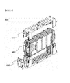
- FIG. 2 is an exploded perspective view typically showing a battery module according to an embodiment of the present invention.
- the buffering member 300 is formed of a polymer resin having a porous structure. Consequently, the buffering member 300 buffers volume change of the battery cells caused by the repetitive expansion and contraction change of the battery cells during charge and discharge of the battery cells and increases frictional force between the battery cells to restrain movement of the battery cells.
- the module housings 200 include a pair of module housings 200 coupled to entirely cover the outside of a stack of the battery cells 100 excluding the electrode terminals 110 and 120 of the battery cells 100.
- the module housings 200 restrain the repetitive expansion and contraction change of the battery cells during charge and discharge of the battery cells, while protecting the battery cells having low mechanical strength, thereby preventing separation between sealed regions of the battery cells.
- FIG. 3 is a perspective view typically showing the module housings of FIG. 2 .
- each of the module housings 200 is provided at sides adjacent to opposite ends thereof with steps 240 to easily fix the battery module.
- each of the module housings 200 is provided at the outside thereof with a plurality of linear beads 233 spaced apart from each other in the width direction.
- Each of the beads 233 has opposite ends reaching corresponding ends of the module housings. Consequently, a coolant (for example, air) can flow in the width direction of the module housings in a state in which battery modules are stacked, thereby further improving cooling efficiency.
- a coolant for example, air
- each of the module housings 200 is provided at the top and bottom thereof with bars 235 having opposite shapes in the width direction (lateral direction).
- each of the battery modules has a shape corresponding to that of one adjacent battery module with the result that it is possible to prevent stacked positions of the battery modules from being reversed or misaligned.
- the module housings 200 include a pair of a left housing 211 and a right housing 212, which can be coupled to each other without using additional fastening members.
- FIG. 4 is a sectional view and partially enlarged views showing the module housings 200.
- the module housings 211 and 212 are configured to have male and female fastening structures 221 and 222, by which the module housings 211 and 212 are engaged with each other by elastic coupling when the module housings 211 and 212 are pressed in a state in which the module housings 211 and 212 are in contact with each other such that the module housings 211 and 212 face each other.
- Various fastening structures may be used.
- hexahedral fastening structures 221a and 222a and cylindrical fastening structures 221b and 222b may be used.
- the fastening structures are engaged with each other to increased coupling force.
- FIG. 5 is a perspective view showing a middle or large-sized battery pack 500 in which a plurality of unit battery modules 400 is stacked.
- Four unit battery modules 400 according to the present invention constitute one middle or large-sized battery pack 500. Consequently, the middle or large-sized battery pack 500 includes a total of eight battery cells 100. That is, a stack of the four unit battery modules 400 is mounted in pack frames 510 and 520 in a state in which the stack of four unit battery modules 400 is erected in the lateral direction, whereby the middle or large-sized battery pack 500 is manufactured.
- a plurality of battery packs 500 may be connected to manufacture a middle or large-sized battery system having higher power and larger capacity.
- the battery module according to the present invention low mechanical strength of the battery cells is increased by the module housings, and movement of the battery cells is restrained and the volume change of the battery cells during charge and discharge of the battery cells are buffered by the buffing member. Consequently, it is possible to improve operation and lifespan characteristics of the battery module and secure stability and safety of the battery module against external force.
Landscapes
- Chemical & Material Sciences (AREA)
- General Chemical & Material Sciences (AREA)
- Electrochemistry (AREA)
- Chemical Kinetics & Catalysis (AREA)
- Engineering & Computer Science (AREA)
- Power Engineering (AREA)
- Mechanical Engineering (AREA)
- Transportation (AREA)
- Life Sciences & Earth Sciences (AREA)
- Sustainable Energy (AREA)
- Sustainable Development (AREA)
- Inorganic Chemistry (AREA)
- Manufacturing & Machinery (AREA)
- Battery Mounting, Suspending (AREA)
- Sealing Battery Cases Or Jackets (AREA)
- Secondary Cells (AREA)
Applications Claiming Priority (2)
| Application Number | Priority Date | Filing Date | Title |
|---|---|---|---|
| KR1020100114779A KR101281744B1 (ko) | 2010-11-18 | 2010-11-18 | 안전성의 향상을 위한 부재를 전지셀들 사이에 포함하고 있는 전지모듈 |
| PCT/KR2011/008322 WO2012067365A2 (ko) | 2010-11-18 | 2011-11-03 | 안전성이 향상된 전지모듈 |
Publications (3)
| Publication Number | Publication Date |
|---|---|
| EP2624337A2 true EP2624337A2 (de) | 2013-08-07 |
| EP2624337A4 EP2624337A4 (de) | 2016-01-13 |
| EP2624337B1 EP2624337B1 (de) | 2018-08-01 |
Family
ID=46084470
Family Applications (1)
| Application Number | Title | Priority Date | Filing Date |
|---|---|---|---|
| EP11842228.6A Active EP2624337B1 (de) | 2010-11-18 | 2011-11-03 | Batteriemodul mit erhöhter sicherheit |
Country Status (6)
| Country | Link |
|---|---|
| US (1) | US9929385B2 (de) |
| EP (1) | EP2624337B1 (de) |
| JP (1) | JP6001547B2 (de) |
| KR (1) | KR101281744B1 (de) |
| CN (1) | CN103201881A (de) |
| WO (1) | WO2012067365A2 (de) |
Families Citing this family (28)
| Publication number | Priority date | Publication date | Assignee | Title |
|---|---|---|---|---|
| KR101716884B1 (ko) * | 2012-08-01 | 2017-03-27 | 주식회사 엘지화학 | 배터리 모듈 |
| US9236592B2 (en) * | 2012-11-27 | 2016-01-12 | Ford Global Technologies, Llc | Protective vehicle battery cage and method of making a battery cage |
| WO2015103548A1 (en) | 2014-01-03 | 2015-07-09 | Quantumscape Corporation | Thermal management system for vehicles with an electric powertrain |
| US11011783B2 (en) | 2013-10-25 | 2021-05-18 | Quantumscape Battery, Inc. | Thermal and electrical management of battery packs |
| KR101902447B1 (ko) * | 2014-01-17 | 2018-11-13 | 주식회사 엘지화학 | 탄성 외장 부재를 포함하는 유닛모듈 |
| US9834114B2 (en) | 2014-08-27 | 2017-12-05 | Quantumscape Corporation | Battery thermal management system and methods of use |
| WO2016179557A1 (en) * | 2015-05-06 | 2016-11-10 | A123 Systems Llc | Battery crush protection system |
| KR20160148316A (ko) | 2015-06-16 | 2016-12-26 | 삼성에스디아이 주식회사 | 이차 전지 |
| KR102051109B1 (ko) * | 2015-10-08 | 2019-12-02 | 주식회사 엘지화학 | 전지 모듈 |
| WO2018033880A2 (en) | 2016-08-17 | 2018-02-22 | Shape Corp. | Battery support and protection structure for a vehicle |
| KR102018301B1 (ko) | 2016-09-01 | 2019-09-04 | 주식회사 엘지화학 | 배터리 모듈 및 그 제조 방법 |
| WO2018127832A1 (en) | 2017-01-04 | 2018-07-12 | Shape Corp. | Vehicle battery tray structure with nodal modularity |
| WO2018213475A1 (en) | 2017-05-16 | 2018-11-22 | Shape Corp. | Polarized battery tray for a vehicle |
| WO2018213383A1 (en) | 2017-05-16 | 2018-11-22 | Shape Corp. | Vehicle battery tray with integrated battery retention and support features |
| US10886513B2 (en) | 2017-05-16 | 2021-01-05 | Shape Corp. | Vehicle battery tray having tub-based integration |
| KR102201342B1 (ko) | 2017-07-06 | 2021-01-08 | 주식회사 엘지화학 | 배터리 모듈과 이를 포함하는 배터리 팩 및 자동차 |
| US12347879B2 (en) | 2017-09-13 | 2025-07-01 | Shape Corp. | Vehicle battery tray with tubular peripheral wall |
| WO2019055658A2 (en) | 2017-09-13 | 2019-03-21 | Shape Corp. | VEHICLE BATTERY TRAY WITH TUBULAR PERIPHERAL WALL |
| WO2019071013A1 (en) | 2017-10-04 | 2019-04-11 | Shape Corp. | BATTERY SUPPORT BOTTOM ASSEMBLY FOR ELECTRIC VEHICLES |
| US10581041B2 (en) * | 2017-10-24 | 2020-03-03 | Ford Global Technologies, Llc | Battery array plate assembly with pressure retention pad |
| EP3759761B1 (de) | 2018-03-01 | 2026-04-08 | Shape Corp. | In fahrzeugbatteriefach integriertes kühlsystem |
| US11688910B2 (en) | 2018-03-15 | 2023-06-27 | Shape Corp. | Vehicle battery tray having tub-based component |
| JP2019220360A (ja) * | 2018-06-20 | 2019-12-26 | ソフトバンク株式会社 | 電池の製造方法及び電池 |
| EP3736873A1 (de) * | 2019-05-10 | 2020-11-11 | Andreas Stihl AG & Co. KG | Akkupack, bearbeitungssystem und verfahren zur herstellung eines akkupacks |
| KR102886192B1 (ko) * | 2020-10-05 | 2025-11-13 | 주식회사 엘지에너지솔루션 | 전지 셀의 손상 방지를 위한 완충 패드를 포함하는 전지 모듈 및 이를 포함하는 전지 팩 |
| KR20230052657A (ko) * | 2021-10-13 | 2023-04-20 | 주식회사 엘지에너지솔루션 | 소화 및 냉각 기능을 갖는 단열 패드가 구비된 전지 모듈 및 이를 포함하는 전지 팩 |
| JP7436944B1 (ja) * | 2022-04-06 | 2024-02-22 | 日本製鉄株式会社 | バーリング構造部材 |
| CN114784441B (zh) | 2022-06-22 | 2022-10-25 | 宁德时代新能源科技股份有限公司 | 电池以及用电装置 |
Family Cites Families (21)
| Publication number | Priority date | Publication date | Assignee | Title |
|---|---|---|---|---|
| JP4237557B2 (ja) * | 2003-06-26 | 2009-03-11 | Tdk株式会社 | 電池パック |
| JP4547886B2 (ja) | 2003-09-30 | 2010-09-22 | トヨタ自動車株式会社 | 組電池 |
| JP4445737B2 (ja) * | 2003-10-06 | 2010-04-07 | 日本電気株式会社 | ラミネート型電池、前記ラミネート型電池用の保護部材および電池ユニット |
| EP2450981B1 (de) * | 2004-12-24 | 2014-03-19 | Lg Chem, Ltd. | Sekundärbatteriemodul |
| KR100905391B1 (ko) | 2004-12-24 | 2009-06-30 | 주식회사 엘지화학 | 이차전지 모듈의 단자 연결부재 |
| KR100612239B1 (ko) * | 2005-04-26 | 2006-08-11 | 삼성에스디아이 주식회사 | 이차 전지 모듈과 이차 전지 모듈을 이루는 이차 전지의격벽 |
| JP4749774B2 (ja) * | 2005-06-16 | 2011-08-17 | 本田技研工業株式会社 | 組電池 |
| KR100948970B1 (ko) | 2006-03-13 | 2010-03-23 | 주식회사 엘지화학 | 완충부재가 설치되어 있는 중대형 전지모듈 |
| KR100942986B1 (ko) | 2006-03-21 | 2010-02-17 | 주식회사 엘지화학 | 전지셀 사이에 접착부재가 부착되어 있는 전지모듈 |
| KR100895203B1 (ko) * | 2006-05-15 | 2009-05-06 | 주식회사 엘지화학 | 중대형 전지모듈 |
| JP5638183B2 (ja) * | 2006-07-13 | 2014-12-10 | 株式会社Gsユアサ | 扁平形電池の複数個を積層した組電池 |
| KR101244736B1 (ko) * | 2006-08-17 | 2013-03-18 | 삼성에스디아이 주식회사 | 전지 모듈 |
| KR101005607B1 (ko) * | 2006-10-30 | 2011-01-05 | 주식회사 엘지화학 | 완충 부재를 포함하고 있는 전지모듈 |
| JP5094215B2 (ja) * | 2007-05-30 | 2012-12-12 | 三洋電機株式会社 | 電池および組電池 |
| JP4508221B2 (ja) * | 2007-08-27 | 2010-07-21 | 豊田合成株式会社 | 組電池装置 |
| JP5040611B2 (ja) * | 2007-11-22 | 2012-10-03 | 株式会社明電舎 | 電気化学素子のプロテクタ |
| WO2009073225A1 (en) * | 2007-12-05 | 2009-06-11 | Enerdel, Inc. | Battery assembly with temperature control device |
| US20100104927A1 (en) * | 2008-10-29 | 2010-04-29 | Scott Albright | Temperature-controlled battery configuration |
| CN102369625A (zh) * | 2009-04-01 | 2012-03-07 | 株式会社Lg化学 | 在模块结构的设计方面具有灵活性的电池模块和包括此电池模块的中大型电池组 |
| US8173294B2 (en) * | 2009-04-28 | 2012-05-08 | Lightening Energy | High voltage modular battery with electrically-insulated cell module and interconnector peripheries |
| US9147916B2 (en) * | 2010-04-17 | 2015-09-29 | Lg Chem, Ltd. | Battery cell assemblies |
-
2010
- 2010-11-18 KR KR1020100114779A patent/KR101281744B1/ko active Active
-
2011
- 2011-11-03 JP JP2013539748A patent/JP6001547B2/ja active Active
- 2011-11-03 WO PCT/KR2011/008322 patent/WO2012067365A2/ko not_active Ceased
- 2011-11-03 CN CN2011800529185A patent/CN103201881A/zh active Pending
- 2011-11-03 EP EP11842228.6A patent/EP2624337B1/de active Active
-
2013
- 2013-04-23 US US13/868,502 patent/US9929385B2/en active Active
Also Published As
| Publication number | Publication date |
|---|---|
| JP2014501022A (ja) | 2014-01-16 |
| WO2012067365A2 (ko) | 2012-05-24 |
| KR20120053589A (ko) | 2012-05-29 |
| EP2624337B1 (de) | 2018-08-01 |
| CN103201881A (zh) | 2013-07-10 |
| US9929385B2 (en) | 2018-03-27 |
| WO2012067365A3 (ko) | 2012-07-12 |
| KR101281744B1 (ko) | 2013-07-04 |
| JP6001547B2 (ja) | 2016-10-05 |
| US20130230759A1 (en) | 2013-09-05 |
| EP2624337A4 (de) | 2016-01-13 |
Similar Documents
| Publication | Publication Date | Title |
|---|---|---|
| EP2624337B1 (de) | Batteriemodul mit erhöhter sicherheit | |
| EP2827403B1 (de) | Batteriemodul mit erhöhter stabilität | |
| EP2416439B1 (de) | Batteriemodul aufweisend eine hervorragende wärmeabstrahlungfähigkeit und batteriepack damit | |
| KR101150247B1 (ko) | 모듈의 구조 설계에 유연성을 가진 전지모듈 및 이를 포함하는 중대형 전지팩 | |
| KR101392799B1 (ko) | 안정성이 향상된 구조 및 높은 냉각 효율성을 갖는 전지모듈 | |
| EP2860795B1 (de) | Batteriemodul mit montagekopplungsstruktur | |
| EP2725650B1 (de) | Batteriemodul mit erhöhter stabilität | |
| EP2299511B1 (de) | Wiederaufladbare Batterie und Batteriemodul | |
| EP2988344B1 (de) | Batteriemodul mit neuartiger struktur und batteriepack damit | |
| KR101492019B1 (ko) | 벤팅 유도부를 포함하는 전지모듈 | |
| CN110637380A (zh) | 电源装置和具备其的车辆、蓄电装置以及电源装置用隔板 | |
| CN111684618A (zh) | 电源装置以及具备该电源装置的电动车辆和蓄电装置 | |
| CN111937178B (zh) | 电源装置以及具有该电源装置的车辆 | |
| KR20120074425A (ko) | 전지모듈 및 이를 포함하는 전지팩 | |
| KR20150000090A (ko) | 가압 브라켓을 포함하는 전지모듈 | |
| KR20140144784A (ko) | 간접 냉각 구조를 포함하는 전지모듈 | |
| KR100897179B1 (ko) | 중대형 전지모듈 제조용 프레임 부재 | |
| KR101325037B1 (ko) | 제조공정성이 향상된 전지모듈 | |
| KR101818514B1 (ko) | 체결용 클립을 포함하는 전지모듈 |
Legal Events
| Date | Code | Title | Description |
|---|---|---|---|
| PUAI | Public reference made under article 153(3) epc to a published international application that has entered the european phase |
Free format text: ORIGINAL CODE: 0009012 |
|
| 17P | Request for examination filed |
Effective date: 20130429 |
|
| AK | Designated contracting states |
Kind code of ref document: A2 Designated state(s): AL AT BE BG CH CY CZ DE DK EE ES FI FR GB GR HR HU IE IS IT LI LT LU LV MC MK MT NL NO PL PT RO RS SE SI SK SM TR |
|
| DAX | Request for extension of the european patent (deleted) | ||
| RIN1 | Information on inventor provided before grant (corrected) |
Inventor name: YOON, JONG MOON Inventor name: LEE, JIN KYU Inventor name: CHOI, JUNSEOK Inventor name: JEONG, SANG YOON |
|
| A4 | Supplementary search report drawn up and despatched |
Effective date: 20151210 |
|
| RIC1 | Information provided on ipc code assigned before grant |
Ipc: H01M 2/10 20060101ALI20151204BHEP Ipc: B60L 11/18 20060101ALI20151204BHEP Ipc: H01M 2/08 20060101ALI20151204BHEP Ipc: H01M 2/34 20060101AFI20151204BHEP |
|
| RIC1 | Information provided on ipc code assigned before grant |
Ipc: B60L 11/18 20060101ALI20180319BHEP Ipc: H01M 2/20 20060101ALI20180319BHEP Ipc: H01M 2/10 20060101ALI20180319BHEP Ipc: H01M 2/08 20060101ALI20180319BHEP Ipc: H01M 2/02 20060101ALI20180319BHEP Ipc: H01M 2/34 20060101AFI20180319BHEP Ipc: B60L 3/00 20060101ALI20180319BHEP |
|
| GRAP | Despatch of communication of intention to grant a patent |
Free format text: ORIGINAL CODE: EPIDOSNIGR1 |
|
| STAA | Information on the status of an ep patent application or granted ep patent |
Free format text: STATUS: GRANT OF PATENT IS INTENDED |
|
| INTG | Intention to grant announced |
Effective date: 20180502 |
|
| GRAS | Grant fee paid |
Free format text: ORIGINAL CODE: EPIDOSNIGR3 |
|
| GRAJ | Information related to disapproval of communication of intention to grant by the applicant or resumption of examination proceedings by the epo deleted |
Free format text: ORIGINAL CODE: EPIDOSDIGR1 |
|
| GRAL | Information related to payment of fee for publishing/printing deleted |
Free format text: ORIGINAL CODE: EPIDOSDIGR3 |
|
| STAA | Information on the status of an ep patent application or granted ep patent |
Free format text: STATUS: REQUEST FOR EXAMINATION WAS MADE |
|
| GRAR | Information related to intention to grant a patent recorded |
Free format text: ORIGINAL CODE: EPIDOSNIGR71 |
|
| STAA | Information on the status of an ep patent application or granted ep patent |
Free format text: STATUS: GRANT OF PATENT IS INTENDED |
|
| GRAA | (expected) grant |
Free format text: ORIGINAL CODE: 0009210 |
|
| STAA | Information on the status of an ep patent application or granted ep patent |
Free format text: STATUS: THE PATENT HAS BEEN GRANTED |
|
| INTC | Intention to grant announced (deleted) | ||
| INTG | Intention to grant announced |
Effective date: 20180621 |
|
| AK | Designated contracting states |
Kind code of ref document: B1 Designated state(s): AL AT BE BG CH CY CZ DE DK EE ES FI FR GB GR HR HU IE IS IT LI LT LU LV MC MK MT NL NO PL PT RO RS SE SI SK SM TR |
|
| REG | Reference to a national code |
Ref country code: GB Ref legal event code: FG4D |
|
| REG | Reference to a national code |
Ref country code: CH Ref legal event code: EP Ref country code: AT Ref legal event code: REF Ref document number: 1025382 Country of ref document: AT Kind code of ref document: T Effective date: 20180815 |
|
| REG | Reference to a national code |
Ref country code: IE Ref legal event code: FG4D |
|
| REG | Reference to a national code |
Ref country code: DE Ref legal event code: R096 Ref document number: 602011050663 Country of ref document: DE |
|
| RAP2 | Party data changed (patent owner data changed or rights of a patent transferred) |
Owner name: LG CHEM, LTD. |
|
| REG | Reference to a national code |
Ref country code: FR Ref legal event code: PLFP Year of fee payment: 8 |
|
| REG | Reference to a national code |
Ref country code: NL Ref legal event code: MP Effective date: 20180801 |
|
| REG | Reference to a national code |
Ref country code: LT Ref legal event code: MG4D |
|
| REG | Reference to a national code |
Ref country code: AT Ref legal event code: MK05 Ref document number: 1025382 Country of ref document: AT Kind code of ref document: T Effective date: 20180801 |
|
| PG25 | Lapsed in a contracting state [announced via postgrant information from national office to epo] |
Ref country code: RS Free format text: LAPSE BECAUSE OF FAILURE TO SUBMIT A TRANSLATION OF THE DESCRIPTION OR TO PAY THE FEE WITHIN THE PRESCRIBED TIME-LIMIT Effective date: 20180801 Ref country code: PL Free format text: LAPSE BECAUSE OF FAILURE TO SUBMIT A TRANSLATION OF THE DESCRIPTION OR TO PAY THE FEE WITHIN THE PRESCRIBED TIME-LIMIT Effective date: 20180801 Ref country code: IS Free format text: LAPSE BECAUSE OF FAILURE TO SUBMIT A TRANSLATION OF THE DESCRIPTION OR TO PAY THE FEE WITHIN THE PRESCRIBED TIME-LIMIT Effective date: 20181201 Ref country code: LT Free format text: LAPSE BECAUSE OF FAILURE TO SUBMIT A TRANSLATION OF THE DESCRIPTION OR TO PAY THE FEE WITHIN THE PRESCRIBED TIME-LIMIT Effective date: 20180801 Ref country code: NL Free format text: LAPSE BECAUSE OF FAILURE TO SUBMIT A TRANSLATION OF THE DESCRIPTION OR TO PAY THE FEE WITHIN THE PRESCRIBED TIME-LIMIT Effective date: 20180801 Ref country code: BG Free format text: LAPSE BECAUSE OF FAILURE TO SUBMIT A TRANSLATION OF THE DESCRIPTION OR TO PAY THE FEE WITHIN THE PRESCRIBED TIME-LIMIT Effective date: 20181101 Ref country code: SE Free format text: LAPSE BECAUSE OF FAILURE TO SUBMIT A TRANSLATION OF THE DESCRIPTION OR TO PAY THE FEE WITHIN THE PRESCRIBED TIME-LIMIT Effective date: 20180801 Ref country code: GR Free format text: LAPSE BECAUSE OF FAILURE TO SUBMIT A TRANSLATION OF THE DESCRIPTION OR TO PAY THE FEE WITHIN THE PRESCRIBED TIME-LIMIT Effective date: 20181102 Ref country code: FI Free format text: LAPSE BECAUSE OF FAILURE TO SUBMIT A TRANSLATION OF THE DESCRIPTION OR TO PAY THE FEE WITHIN THE PRESCRIBED TIME-LIMIT Effective date: 20180801 Ref country code: AT Free format text: LAPSE BECAUSE OF FAILURE TO SUBMIT A TRANSLATION OF THE DESCRIPTION OR TO PAY THE FEE WITHIN THE PRESCRIBED TIME-LIMIT Effective date: 20180801 Ref country code: NO Free format text: LAPSE BECAUSE OF FAILURE TO SUBMIT A TRANSLATION OF THE DESCRIPTION OR TO PAY THE FEE WITHIN THE PRESCRIBED TIME-LIMIT Effective date: 20181101 |
|
| PG25 | Lapsed in a contracting state [announced via postgrant information from national office to epo] |
Ref country code: HR Free format text: LAPSE BECAUSE OF FAILURE TO SUBMIT A TRANSLATION OF THE DESCRIPTION OR TO PAY THE FEE WITHIN THE PRESCRIBED TIME-LIMIT Effective date: 20180801 Ref country code: LV Free format text: LAPSE BECAUSE OF FAILURE TO SUBMIT A TRANSLATION OF THE DESCRIPTION OR TO PAY THE FEE WITHIN THE PRESCRIBED TIME-LIMIT Effective date: 20180801 Ref country code: AL Free format text: LAPSE BECAUSE OF FAILURE TO SUBMIT A TRANSLATION OF THE DESCRIPTION OR TO PAY THE FEE WITHIN THE PRESCRIBED TIME-LIMIT Effective date: 20180801 |
|
| PG25 | Lapsed in a contracting state [announced via postgrant information from national office to epo] |
Ref country code: EE Free format text: LAPSE BECAUSE OF FAILURE TO SUBMIT A TRANSLATION OF THE DESCRIPTION OR TO PAY THE FEE WITHIN THE PRESCRIBED TIME-LIMIT Effective date: 20180801 Ref country code: IT Free format text: LAPSE BECAUSE OF FAILURE TO SUBMIT A TRANSLATION OF THE DESCRIPTION OR TO PAY THE FEE WITHIN THE PRESCRIBED TIME-LIMIT Effective date: 20180801 Ref country code: RO Free format text: LAPSE BECAUSE OF FAILURE TO SUBMIT A TRANSLATION OF THE DESCRIPTION OR TO PAY THE FEE WITHIN THE PRESCRIBED TIME-LIMIT Effective date: 20180801 Ref country code: CZ Free format text: LAPSE BECAUSE OF FAILURE TO SUBMIT A TRANSLATION OF THE DESCRIPTION OR TO PAY THE FEE WITHIN THE PRESCRIBED TIME-LIMIT Effective date: 20180801 Ref country code: ES Free format text: LAPSE BECAUSE OF FAILURE TO SUBMIT A TRANSLATION OF THE DESCRIPTION OR TO PAY THE FEE WITHIN THE PRESCRIBED TIME-LIMIT Effective date: 20180801 |
|
| REG | Reference to a national code |
Ref country code: DE Ref legal event code: R097 Ref document number: 602011050663 Country of ref document: DE |
|
| PG25 | Lapsed in a contracting state [announced via postgrant information from national office to epo] |
Ref country code: SM Free format text: LAPSE BECAUSE OF FAILURE TO SUBMIT A TRANSLATION OF THE DESCRIPTION OR TO PAY THE FEE WITHIN THE PRESCRIBED TIME-LIMIT Effective date: 20180801 Ref country code: SK Free format text: LAPSE BECAUSE OF FAILURE TO SUBMIT A TRANSLATION OF THE DESCRIPTION OR TO PAY THE FEE WITHIN THE PRESCRIBED TIME-LIMIT Effective date: 20180801 Ref country code: DK Free format text: LAPSE BECAUSE OF FAILURE TO SUBMIT A TRANSLATION OF THE DESCRIPTION OR TO PAY THE FEE WITHIN THE PRESCRIBED TIME-LIMIT Effective date: 20180801 |
|
| PLBE | No opposition filed within time limit |
Free format text: ORIGINAL CODE: 0009261 |
|
| STAA | Information on the status of an ep patent application or granted ep patent |
Free format text: STATUS: NO OPPOSITION FILED WITHIN TIME LIMIT |
|
| REG | Reference to a national code |
Ref country code: CH Ref legal event code: PL |
|
| 26N | No opposition filed |
Effective date: 20190503 |
|
| PG25 | Lapsed in a contracting state [announced via postgrant information from national office to epo] |
Ref country code: LU Free format text: LAPSE BECAUSE OF NON-PAYMENT OF DUE FEES Effective date: 20181103 Ref country code: MC Free format text: LAPSE BECAUSE OF FAILURE TO SUBMIT A TRANSLATION OF THE DESCRIPTION OR TO PAY THE FEE WITHIN THE PRESCRIBED TIME-LIMIT Effective date: 20180801 |
|
| REG | Reference to a national code |
Ref country code: BE Ref legal event code: MM Effective date: 20181130 |
|
| REG | Reference to a national code |
Ref country code: IE Ref legal event code: MM4A |
|
| PG25 | Lapsed in a contracting state [announced via postgrant information from national office to epo] |
Ref country code: SI Free format text: LAPSE BECAUSE OF FAILURE TO SUBMIT A TRANSLATION OF THE DESCRIPTION OR TO PAY THE FEE WITHIN THE PRESCRIBED TIME-LIMIT Effective date: 20180801 Ref country code: CH Free format text: LAPSE BECAUSE OF NON-PAYMENT OF DUE FEES Effective date: 20181130 Ref country code: LI Free format text: LAPSE BECAUSE OF NON-PAYMENT OF DUE FEES Effective date: 20181130 |
|
| PG25 | Lapsed in a contracting state [announced via postgrant information from national office to epo] |
Ref country code: IE Free format text: LAPSE BECAUSE OF NON-PAYMENT OF DUE FEES Effective date: 20181103 |
|
| PG25 | Lapsed in a contracting state [announced via postgrant information from national office to epo] |
Ref country code: BE Free format text: LAPSE BECAUSE OF NON-PAYMENT OF DUE FEES Effective date: 20181130 |
|
| PG25 | Lapsed in a contracting state [announced via postgrant information from national office to epo] |
Ref country code: MT Free format text: LAPSE BECAUSE OF NON-PAYMENT OF DUE FEES Effective date: 20181103 |
|
| PG25 | Lapsed in a contracting state [announced via postgrant information from national office to epo] |
Ref country code: TR Free format text: LAPSE BECAUSE OF FAILURE TO SUBMIT A TRANSLATION OF THE DESCRIPTION OR TO PAY THE FEE WITHIN THE PRESCRIBED TIME-LIMIT Effective date: 20180801 |
|
| PG25 | Lapsed in a contracting state [announced via postgrant information from national office to epo] |
Ref country code: PT Free format text: LAPSE BECAUSE OF FAILURE TO SUBMIT A TRANSLATION OF THE DESCRIPTION OR TO PAY THE FEE WITHIN THE PRESCRIBED TIME-LIMIT Effective date: 20180801 |
|
| PG25 | Lapsed in a contracting state [announced via postgrant information from national office to epo] |
Ref country code: MK Free format text: LAPSE BECAUSE OF NON-PAYMENT OF DUE FEES Effective date: 20180801 Ref country code: HU Free format text: LAPSE BECAUSE OF FAILURE TO SUBMIT A TRANSLATION OF THE DESCRIPTION OR TO PAY THE FEE WITHIN THE PRESCRIBED TIME-LIMIT; INVALID AB INITIO Effective date: 20111103 Ref country code: CY Free format text: LAPSE BECAUSE OF FAILURE TO SUBMIT A TRANSLATION OF THE DESCRIPTION OR TO PAY THE FEE WITHIN THE PRESCRIBED TIME-LIMIT Effective date: 20180801 |
|
| REG | Reference to a national code |
Ref country code: DE Ref legal event code: R079 Ref document number: 602011050663 Country of ref document: DE Free format text: PREVIOUS MAIN CLASS: H01M0002340000 Ipc: H01M0050572000 |
|
| P01 | Opt-out of the competence of the unified patent court (upc) registered |
Effective date: 20230512 |
|
| REG | Reference to a national code |
Ref country code: DE Ref legal event code: R081 Ref document number: 602011050663 Country of ref document: DE Owner name: LG ENERGY SOLUTION, LTD., KR Free format text: FORMER OWNER: LG CHEM. LTD., SEOUL/SOUL, KR |
|
| REG | Reference to a national code |
Ref country code: GB Ref legal event code: 732E Free format text: REGISTERED BETWEEN 20230824 AND 20230831 |
|
| PGFP | Annual fee paid to national office [announced via postgrant information from national office to epo] |
Ref country code: DE Payment date: 20251020 Year of fee payment: 15 |
|
| PGFP | Annual fee paid to national office [announced via postgrant information from national office to epo] |
Ref country code: GB Payment date: 20251023 Year of fee payment: 15 |
|
| PGFP | Annual fee paid to national office [announced via postgrant information from national office to epo] |
Ref country code: FR Payment date: 20251021 Year of fee payment: 15 |