EP2624018A2 - Aide pour alignement laser intégré à l'aide de plusieurs points laser hors d'un simple laser - Google Patents
Aide pour alignement laser intégré à l'aide de plusieurs points laser hors d'un simple laser Download PDFInfo
- Publication number
- EP2624018A2 EP2624018A2 EP12165326.5A EP12165326A EP2624018A2 EP 2624018 A2 EP2624018 A2 EP 2624018A2 EP 12165326 A EP12165326 A EP 12165326A EP 2624018 A2 EP2624018 A2 EP 2624018A2
- Authority
- EP
- European Patent Office
- Prior art keywords
- optical
- alignment
- optical unit
- radiation
- light
- Prior art date
- Legal status (The legal status is an assumption and is not a legal conclusion. Google has not performed a legal analysis and makes no representation as to the accuracy of the status listed.)
- Granted
Links
- 230000003287 optical effect Effects 0.000 claims abstract description 221
- 230000005855 radiation Effects 0.000 claims abstract description 113
- 238000012545 processing Methods 0.000 claims abstract description 78
- 230000001681 protective effect Effects 0.000 claims abstract description 13
- 238000012544 monitoring process Methods 0.000 claims abstract description 9
- 239000000463 material Substances 0.000 claims description 20
- 239000004033 plastic Substances 0.000 claims description 7
- 229920003023 plastic Polymers 0.000 claims description 7
- VYPSYNLAJGMNEJ-UHFFFAOYSA-N silicon dioxide Inorganic materials O=[Si]=O VYPSYNLAJGMNEJ-UHFFFAOYSA-N 0.000 claims description 7
- 239000011521 glass Substances 0.000 claims description 5
- 239000010453 quartz Substances 0.000 claims description 3
- 230000004888 barrier function Effects 0.000 claims 2
- ORQBXQOJMQIAOY-UHFFFAOYSA-N nobelium Chemical compound [No] ORQBXQOJMQIAOY-UHFFFAOYSA-N 0.000 description 34
- 238000004519 manufacturing process Methods 0.000 description 14
- 230000008901 benefit Effects 0.000 description 11
- 238000000465 moulding Methods 0.000 description 10
- 239000013078 crystal Substances 0.000 description 9
- 238000000034 method Methods 0.000 description 9
- 238000009826 distribution Methods 0.000 description 7
- 230000006870 function Effects 0.000 description 5
- 230000000737 periodic effect Effects 0.000 description 4
- 230000008569 process Effects 0.000 description 4
- 230000001419 dependent effect Effects 0.000 description 3
- 238000010276 construction Methods 0.000 description 2
- 239000005350 fused silica glass Substances 0.000 description 2
- 239000003292 glue Substances 0.000 description 2
- 230000004048 modification Effects 0.000 description 2
- 238000012986 modification Methods 0.000 description 2
- 238000007493 shaping process Methods 0.000 description 2
- 238000000638 solvent extraction Methods 0.000 description 2
- XUIMIQQOPSSXEZ-UHFFFAOYSA-N Silicon Chemical compound [Si] XUIMIQQOPSSXEZ-UHFFFAOYSA-N 0.000 description 1
- XAGFODPZIPBFFR-UHFFFAOYSA-N aluminium Chemical compound [Al] XAGFODPZIPBFFR-UHFFFAOYSA-N 0.000 description 1
- 229910052782 aluminium Inorganic materials 0.000 description 1
- 239000004411 aluminium Substances 0.000 description 1
- 238000005266 casting Methods 0.000 description 1
- 230000001351 cycling effect Effects 0.000 description 1
- 238000005516 engineering process Methods 0.000 description 1
- 238000005286 illumination Methods 0.000 description 1
- 238000007373 indentation Methods 0.000 description 1
- 238000009434 installation Methods 0.000 description 1
- 230000003993 interaction Effects 0.000 description 1
- 238000005459 micromachining Methods 0.000 description 1
- 230000005693 optoelectronics Effects 0.000 description 1
- 230000035515 penetration Effects 0.000 description 1
- 230000002093 peripheral effect Effects 0.000 description 1
- 239000002861 polymer material Substances 0.000 description 1
- 230000009467 reduction Effects 0.000 description 1
- 238000000926 separation method Methods 0.000 description 1
- 229910052710 silicon Inorganic materials 0.000 description 1
- 239000010703 silicon Substances 0.000 description 1
- 239000000377 silicon dioxide Substances 0.000 description 1
- 238000012360 testing method Methods 0.000 description 1
- 230000001131 transforming effect Effects 0.000 description 1
- 230000007704 transition Effects 0.000 description 1
- 238000004804 winding Methods 0.000 description 1
Images


Classifications
-
- G—PHYSICS
- G01—MEASURING; TESTING
- G01B—MEASURING LENGTH, THICKNESS OR SIMILAR LINEAR DIMENSIONS; MEASURING ANGLES; MEASURING AREAS; MEASURING IRREGULARITIES OF SURFACES OR CONTOURS
- G01B11/00—Measuring arrangements characterised by the use of optical techniques
- G01B11/14—Measuring arrangements characterised by the use of optical techniques for measuring distance or clearance between spaced objects or spaced apertures
-
- F—MECHANICAL ENGINEERING; LIGHTING; HEATING; WEAPONS; BLASTING
- F16—ENGINEERING ELEMENTS AND UNITS; GENERAL MEASURES FOR PRODUCING AND MAINTAINING EFFECTIVE FUNCTIONING OF MACHINES OR INSTALLATIONS; THERMAL INSULATION IN GENERAL
- F16P—SAFETY DEVICES IN GENERAL; SAFETY DEVICES FOR PRESSES
- F16P3/00—Safety devices acting in conjunction with the control or operation of a machine; Control arrangements requiring the simultaneous use of two or more parts of the body
- F16P3/12—Safety devices acting in conjunction with the control or operation of a machine; Control arrangements requiring the simultaneous use of two or more parts of the body with means, e.g. feelers, which in case of the presence of a body part of a person in or near the danger zone influence the control or operation of the machine
- F16P3/14—Safety devices acting in conjunction with the control or operation of a machine; Control arrangements requiring the simultaneous use of two or more parts of the body with means, e.g. feelers, which in case of the presence of a body part of a person in or near the danger zone influence the control or operation of the machine the means being photocells or other devices sensitive without mechanical contact
- F16P3/144—Safety devices acting in conjunction with the control or operation of a machine; Control arrangements requiring the simultaneous use of two or more parts of the body with means, e.g. feelers, which in case of the presence of a body part of a person in or near the danger zone influence the control or operation of the machine the means being photocells or other devices sensitive without mechanical contact using light grids
-
- G—PHYSICS
- G01—MEASURING; TESTING
- G01B—MEASURING LENGTH, THICKNESS OR SIMILAR LINEAR DIMENSIONS; MEASURING ANGLES; MEASURING AREAS; MEASURING IRREGULARITIES OF SURFACES OR CONTOURS
- G01B11/00—Measuring arrangements characterised by the use of optical techniques
- G01B11/26—Measuring arrangements characterised by the use of optical techniques for measuring angles or tapers; for testing the alignment of axes
- G01B11/27—Measuring arrangements characterised by the use of optical techniques for measuring angles or tapers; for testing the alignment of axes for testing the alignment of axes
-
- G—PHYSICS
- G01—MEASURING; TESTING
- G01D—MEASURING NOT SPECIALLY ADAPTED FOR A SPECIFIC VARIABLE; ARRANGEMENTS FOR MEASURING TWO OR MORE VARIABLES NOT COVERED IN A SINGLE OTHER SUBCLASS; TARIFF METERING APPARATUS; MEASURING OR TESTING NOT OTHERWISE PROVIDED FOR
- G01D5/00—Mechanical means for transferring the output of a sensing member; Means for converting the output of a sensing member to another variable where the form or nature of the sensing member does not constrain the means for converting; Transducers not specially adapted for a specific variable
- G01D5/26—Mechanical means for transferring the output of a sensing member; Means for converting the output of a sensing member to another variable where the form or nature of the sensing member does not constrain the means for converting; Transducers not specially adapted for a specific variable characterised by optical transfer means, i.e. using infrared, visible, or ultraviolet light
- G01D5/32—Mechanical means for transferring the output of a sensing member; Means for converting the output of a sensing member to another variable where the form or nature of the sensing member does not constrain the means for converting; Transducers not specially adapted for a specific variable characterised by optical transfer means, i.e. using infrared, visible, or ultraviolet light with attenuation or whole or partial obturation of beams of light
- G01D5/34—Mechanical means for transferring the output of a sensing member; Means for converting the output of a sensing member to another variable where the form or nature of the sensing member does not constrain the means for converting; Transducers not specially adapted for a specific variable characterised by optical transfer means, i.e. using infrared, visible, or ultraviolet light with attenuation or whole or partial obturation of beams of light the beams of light being detected by photocells
- G01D5/342—Mechanical means for transferring the output of a sensing member; Means for converting the output of a sensing member to another variable where the form or nature of the sensing member does not constrain the means for converting; Transducers not specially adapted for a specific variable characterised by optical transfer means, i.e. using infrared, visible, or ultraviolet light with attenuation or whole or partial obturation of beams of light the beams of light being detected by photocells the sensed object being the obturating part
-
- G—PHYSICS
- G01—MEASURING; TESTING
- G01V—GEOPHYSICS; GRAVITATIONAL MEASUREMENTS; DETECTING MASSES OR OBJECTS; TAGS
- G01V8/00—Prospecting or detecting by optical means
- G01V8/10—Detecting, e.g. by using light barriers
-
- G—PHYSICS
- G01—MEASURING; TESTING
- G01V—GEOPHYSICS; GRAVITATIONAL MEASUREMENTS; DETECTING MASSES OR OBJECTS; TAGS
- G01V8/00—Prospecting or detecting by optical means
- G01V8/10—Detecting, e.g. by using light barriers
- G01V8/20—Detecting, e.g. by using light barriers using multiple transmitters or receivers
-
- G—PHYSICS
- G02—OPTICS
- G02B—OPTICAL ELEMENTS, SYSTEMS OR APPARATUS
- G02B19/00—Condensers, e.g. light collectors or similar non-imaging optics
- G02B19/0033—Condensers, e.g. light collectors or similar non-imaging optics characterised by the use
- G02B19/0047—Condensers, e.g. light collectors or similar non-imaging optics characterised by the use for use with a light source
- G02B19/0052—Condensers, e.g. light collectors or similar non-imaging optics characterised by the use for use with a light source the light source comprising a laser diode
-
- G—PHYSICS
- G02—OPTICS
- G02B—OPTICAL ELEMENTS, SYSTEMS OR APPARATUS
- G02B27/00—Optical systems or apparatus not provided for by any of the groups G02B1/00 - G02B26/00, G02B30/00
- G02B27/10—Beam splitting or combining systems
- G02B27/106—Beam splitting or combining systems for splitting or combining a plurality of identical beams or images, e.g. image replication
-
- G—PHYSICS
- G02—OPTICS
- G02B—OPTICAL ELEMENTS, SYSTEMS OR APPARATUS
- G02B27/00—Optical systems or apparatus not provided for by any of the groups G02B1/00 - G02B26/00, G02B30/00
- G02B27/10—Beam splitting or combining systems
- G02B27/1086—Beam splitting or combining systems operating by diffraction only
- G02B27/1093—Beam splitting or combining systems operating by diffraction only for use with monochromatic radiation only, e.g. devices for splitting a single laser source
-
- G—PHYSICS
- G02—OPTICS
- G02B—OPTICAL ELEMENTS, SYSTEMS OR APPARATUS
- G02B27/00—Optical systems or apparatus not provided for by any of the groups G02B1/00 - G02B26/00, G02B30/00
- G02B27/10—Beam splitting or combining systems
- G02B27/12—Beam splitting or combining systems operating by refraction only
- G02B27/123—The splitting element being a lens or a system of lenses, including arrays and surfaces with refractive power
-
- G—PHYSICS
- G02—OPTICS
- G02B—OPTICAL ELEMENTS, SYSTEMS OR APPARATUS
- G02B27/00—Optical systems or apparatus not provided for by any of the groups G02B1/00 - G02B26/00, G02B30/00
- G02B27/10—Beam splitting or combining systems
- G02B27/12—Beam splitting or combining systems operating by refraction only
- G02B27/126—The splitting element being a prism or prismatic array, including systems based on total internal reflection
-
- G—PHYSICS
- G08—SIGNALLING
- G08B—SIGNALLING OR CALLING SYSTEMS; ORDER TELEGRAPHS; ALARM SYSTEMS
- G08B13/00—Burglar, theft or intruder alarms
- G08B13/18—Actuation by interference with heat, light, or radiation of shorter wavelength; Actuation by intruding sources of heat, light, or radiation of shorter wavelength
- G08B13/181—Actuation by interference with heat, light, or radiation of shorter wavelength; Actuation by intruding sources of heat, light, or radiation of shorter wavelength using active radiation detection systems
- G08B13/183—Actuation by interference with heat, light, or radiation of shorter wavelength; Actuation by intruding sources of heat, light, or radiation of shorter wavelength using active radiation detection systems by interruption of a radiation beam or barrier
Definitions
- the present invention relates to light curtains, in particular safety light curtains, for monitoring a protective field. Furthermore, the present invention relates to optical units which are part of such a light curtain.
- light curtains detect the movement or intrusion of objects into guarded zones, and more particularly, provide protection for human operators who are working with machines or other industrial equipment.
- Light curtains employing infrared or visible light beams are used to provide operator safety in a variety of industrial applications.
- Light curtains typically are employed for operator protection around machinery, such as punch presses, brakes, molding machines, automatic assembly equipment, coil winding machinery, robot operation, casting operations and the like.
- Conventional light curtains typically employ light emitting diodes (LED) mounted at spaced positions along a transmitter bar at one side of the guard zone and phototransistors (PT), photodiodes or photoreceivers mounted along a receiver bar at the opposite side of the zone.
- the LEDs transmit modulated infrared light beams along separate parallel channels to the PTs at the receiver bar. If one or more beams are blocked from penetration by an opaque object, such as the operator's arm, a control circuit shuts the machine down, prevents the machine from cycling, or otherwise safeguards the area.
- safety light curtains comprise two optical units (called bars, sticks, or strips), which are formed as two different constructional units, one of the optical units having the functionality of an emitter and one of a receiver.
- This dedicated architecture of an emitter and receiver has several drawbacks, for instance the fact that the fabrication costs are high, because each type of optical unit has to be fabricated differently. Consequently, there exist concepts that use an architecture wherein each optical unit has a transceiver unit carrying a plurality of light emitting elements and light receiving elements and at least one separate detachable plug-in module.
- the first and second transceiver units are identically built, whereas the first and second plug-in modules differ from each other and thus define the functionality of the respective optical unit.
- the plug-in module differentiates an optical unit as the emitter with, for instance, the test input, or as the receiver with, for instance, the output signal switching devices, OSSD.
- Such a modular architecture is for instance proposed in the European patent application EP 11162263.5 and allows a very cost-effective fabrication, because the transceiver modules are identically built and, furthermore, can be applied in a very flexible way for a multitude of applications and system configurations.
- this modular transceiver bar configuration is not compatible with laser alignment techniques that employ one laser module as a radiation emitter at each stick, but at different locations for the dedicated receiver and transmitter bar, respectively, as this is for instance shown in the published European patent EP 0889332 B1 .
- the object underlying the present invention is to provide a light curtain and an optical unit for a light curtain, which can be fabricated in a particularly cost-effective way, and allow for an accurate alignment and synchronization.
- the present invention is based on the idea that one laser module in each stick can be employed when using an optical processing element that generates a defined radiation pattern, for instance a row of multiple spots along the axis of the sticks and a target where the spots generated by the opposing laser module are clearly visible or detectable.
- an optical processing element that generates a defined radiation pattern, for instance a row of multiple spots along the axis of the sticks and a target where the spots generated by the opposing laser module are clearly visible or detectable.
- an alignment system for a light curtain monitoring a protective field comprises at least one alignment radiation source being arranged on a first support element of the light curtain and at least one alignment radiation receiver arranged on the second support element.
- This alignment radiation receiver provides an alignment signal indicating a correct positioning of the two support elements with respect to each other.
- the alignment system has at least one optical unit which has an optical processing element for generating a defined pattern from the radiation emitted by the alignment radiation source. This defined pattern can be detected by the alignment radiation receiver and the alignment signal can be generated based on the incident radiation.
- the radiation receiver may be just a target surface where the radiation pattern emitted by the opposing laser module is clearly visible and can be evaluated by an operator adjusting the position of the light curtain system.
- the optical processing element is structured to form in a planar observation region, a plurality of light points arranged in an essentially straight line from the radiation of the laser radiation source.
- a particularly cost effective and on the other hand precisely aligned mounting of the optical unit according to the present invention can be achieved by combining the optical processing element which generates the defined radiation pattern, with at least one additional functional element, such as a lens for focussing the light curtain radiation, and/or an optical waveguide that is needed for guiding the radiation from at least one display radiation source to a surface which is visible to an observer and/or a beam expander.
- a combined optical unit has a size sufficiently large for a facilitated assembly and may even have additional alignment features for being mounted within the housing of a support element, but on the other hand only needs a relatively small part forming the optical processing element.
- the optical unit may for instance be fabricated as a molded part from a plastic material or as a micromachined part made from glass, quartz, or plastic.
- the actual optical processing element may be fabricated from the same material or from a different material as the optical unit.
- the optical unit also incorporates a lens arrangement, in an advantageous way two low tolerance fabrication processes can efficiently be combined because the lenses also have to be fabricated and mounted with particularly high accuracy.
- the optical processing element is incorporated into the optical unit in the frame of a high-precision fabrication step as it is well-established in micro machining technology, its position with regard to the optical waveguides or any other alignment features can be performed accurately and with small tolerances.
- the position of the optical unit with regard to the support element of the light curtain is facilitated because the optical unit is large enough to be mounted in a particularly easy way.
- the optical processing element comprises a micro-structured Diffractive Optical Element (DOE), an optical grating structure and/or a prismatic structure for generating a defined pattern from the radiation emitted by the alignment radiation source.
- DOE Diffractive Optical Element
- prismatic structure for generating a defined pattern from the radiation emitted by the alignment radiation source.
- DOEs utilize surfaces with a complex micro structure for a particular optical function.
- a micro-structured surface relief profile has two or more surface levels.
- the surface structures are for instance etched in fused silica or other glass types, or are embossed in various polymer materials.
- Diffractive Optical Elements work by breaking up incoming waves of light into a large number of waves which re-combine to form completely new waves. They can be fabricated in a wide range of materials, such as aluminium, silicon, silica, plastics etc., providing the user with high flexibility and selecting the material for a particular application.
- a micro-structured DOE is used for generating a defined pattern of light from one single radiation source.
- a plurality of light points is generated which are arranged in an essentially straight line.
- the straight line of light points can be used for evaluating whether the light curtain support elements are correctly aligned with respect to each other.
- any other shape of radiation pattern may be used for performing the alignment.
- concentric circles or parallel lines may be generated from one radiation source.
- the light points have different intensity, the central point having a higher intensity compared to the remaining points for facilitating horizontal and vertical alignment of the support elements.
- uniform intensity can also be chosen.
- DOEs have several significant advantages over conventional refractive optical elements, gratings or prismatic structures may of course also be used in the optical unit according to the present invention.
- the additional optical functional element may also comprise a beam expansion unit for adapting a cross sectional shape of a beam emitted by the alignment radiation source to the dimension of an active area of the optical processing element.
- a beam expansion unit is integrated in the optical unit so that the radiation beam, in most cases a laser beam, has a sufficiently large diameter.
- a lens system according to a Kepler or a Galileo beam expander configuration can be integrated into the optical unit.
- the Kepler arrangement consisting of two positive lenses or groups of lenses
- the Galileo configuration consisting of a negative and a positive subsystem. Due to the reduced installation length, the Galileo arrangement will, in most cases, be preferred for the present invention.
- a cylindrical lens structure preferably formed as one integral part from glass or plastic material can be used as a beam expansion unit.
- the advantage of such a beam expansion unit can be seen in a particularly easy fabrication and a space-saving shape.
- a birefringent element can be used for expanding the radiation beam to be large enough for interacting with the complete optical processing element area.
- the advantage of using a birefringent material can be seen in the fact, that a beam expander unit based thereon is much easier to be fabricated than a double lens system.
- the optical unit itself may comprise a means for aligning the position of the laser with respect to the optical unit and thus to the optical processing element.
- These alignment means may be formed, for instance, by a recess that interacts with passing of the alignment radiation source for accurately positioning same with in the optical unit.
- an alignment shoulder or one or more alignment ribs can be provided in this recess. Providing a shoulder which extends across to the longitudinal axis of the alignment radiation source has the advantage that a much higher accuracy can be achieved.
- the optical processing element comprises a prismatic structure having a plurality of angled surfaces and a uniform base surface opposite to these angle surfaces.
- a prismatic structure having a plurality of angled surfaces and a uniform base surface opposite to these angle surfaces.
- Such a structure may easily be produced and has the advantage of generating the desired radiation pattern in a very flexible and accurate way.
- spots of differing brightness can be generated.
- the plurality of different prisms are all fabricated with one molding tool, if a molding technique is used. By partitioning the tool correspondingly, sharp edges can be achieved for the prismatic structure.
- the overall thickness of the optical processing element can be kept much more uniform, thus facilitating the molding process.
- a light curtain for monitoring a protective field comprises a first support element and a second support element, wherein the protective field is covered by radiation transmitted between these support elements and an alignment system according to the present invention.
- FIG. 1 an optical unit according to the present invention is explained in more detail.
- the optical unit 100 is designed to be mounted within a support element of a light curtain monitoring a protective field.
- the optical unit 100 is combining several optical functions as one integral part: Firstly, it accommodates an optical processing element 102 for generating a defined radiation pattern from the radiation which is emitted by an alignment radiation source (not shown in the figure).
- the optical processing element 102 may for instance comprise a micro-structured Diffractive Optical Element (DOE) which transforms the radiation emitted by a radiation source, such as a laser diode, into a pattern that can be used advantageously for aligning a support element to which the optical unit 100 is connected with respect to a second support element of a light curtain arranged in some distance thereto.
- DOE micro-structured Diffractive Optical Element
- optical unit 100 may advantageously be used also for other alignment tasks which utilize optical radiation for the actual alignment.
- the optical processing element 102 may form a row of light dots, an array of light dots, a plurality of lines, concentric circles or square structures or any other suitable form from the incident laser beam which can be used for an alignment.
- a linear pattern is an advantageous means for detecting a misalignment of two light curtain support elements with respect to each other.
- the optical processing element 102 is embedded integrally within the main body 104 of the optical unit 100.
- Such a construction can either be achieved by forming the optical processing element 102 directly from the same material as the main body 104 or by separately manufacturing the optical processing element 102 and—for instance—overmolding same when fabricating the main body 104.
- the optical unit 100 is produced from a plastic material, or from glass or quartz, either as a molded part or as a micro-machined part.
- one or more optical waveguides 106 are integrally formed with the main body 104.
- the optical waveguides 106 guide radiation from at least one display radiation source (not shown in the figures) to a surface 108 of the optical element which is visible for an observer.
- Such a compact construction of the optical unit 100 allows for a much more precise alignment of the optical processing element 102 with respect to a support element of a light curtain, because of the larger size and the oblong form.
- the position of the optically active structures of the optical processing element 102 with respect to the main body 104 of the optical unit can be adjusted during a high-precision fabrication step when producing the optical unit 100, whereas the alignment of the optical unit 100 in a support element is done by a mechanical fit, as this will be explained later with respect to FIG. 18 .
- the optical unit 100 additionally comprises an array of lenses 107 which will be mounted in a way that they focus incident light curtain radiation onto a receiver element and/or form an emitted radiation beam from an emitter element.
- a row of 18 lenses is integrally formed with the optical processing element 102 and the optical waveguides 106.
- a lens array even differently shaped
- any other required optical functional elements may be combined with the optical processing element 102 in order to enhance the mounting precision of the optical processing element 102.
- FIG. 2 to 6 show several sectional and side views of the optical unit 100 according to FIG. 1 .
- the optical processing element 102 may comprise a micro-structured DOE.
- a simpler optical grating structure or a prismatic refractive structure may be chosen for forming the desired radiation pattern from the radiation emitted by an alignment radiation source, such as a laser.
- the optical waveguides 106 guide the light from corresponding light sources, such as light-emitting diodes (LEDs) to the outer surface 108 where the light is visible for an observer.
- LEDs light-emitting diodes
- a slightly tapered form of the optical waveguides 106 was chosen in order to generate a sufficiently large light point on the display surface 108.
- FIG. 7 schematically illustrates the functioning of the optical processing element 102 according to one particular example. It has to be mentioned that the present drawing is not to scale, in order to enhance the clarity for the following explanations.
- An alignment radiation source 110 for instance a laser module with a collimator, generates a laser beam 112.
- the laser beam 112 passes through the optical processing element 102.
- this is a Diffractive Optical Element (DOE), which splits the laser beam 112 into a plurality of beams forming a straight line of dots 114 on a target surface 116.
- DOE Diffractive Optical Element
- other radiation patterns 114 than the one schematically shown in FIG. 7 can be achieved.
- the laser beam 112 is split into a radiation pattern 114 having a centre spot with larger intensity and a plurality of smaller light points with lower intensity.
- the distance between the optical processing element 102 and the target surface 116 for the present example may, for instance, be up to 18 m.
- ⁇ max The maximum angle indicated in FIG. 7 , ⁇ max , is around 4.25°, whereas the minimum angle between the central beam and the next following weaker beam, ⁇ min , amounts to about 0.45°.
- the optical unit 100 as shown in Figures 2 to 6 forms part of an alignment system that is used for aligning two sticks of a light curtain with respect to each other.
- FIG. 8 shows the alignment of a first light curtain stick 118 and a second light curtain stick 120.
- the first light curtain stick 118 has a laser radiation emitting device and optical unit according to the present invention
- the second light curtain stick has the function of a target surface.
- both light curtains may be equipped with an alignment radiation source.
- the general idea of aligning light curtain sticks with respect to each other by employing an optical processing element 102 can of course also be realized by only using a radiation source and the optical processing element, as explained with respect to FIG. 7 .
- FIG. 8 the alignment of two rather short light curtain sticks, for instance having a length of about 150 mm, is explained. It is assumed that the first light curtain stick has an alignment radiation source and optical processing elements, which generate a radiation pattern 114, as shown in FIG. 7 .
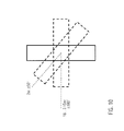
- the allowed rotation for long light curtain sticks is schematically depicted in FIG. 11 .
- the laser spot tolerances for correct operation are given on the right-hand side of FIG. 11
- the maximum possible rotation angle is summarized on the left-hand part of FIG. 11 .
- the maximum possible rotation occurs at 18 m and amounts to ⁇ 45°.
- the alignment system using a radiation pattern at a two metres distance and a length of the light curtain sticks of 1500 mm allows a rotation of 5° of the stick.
- the line of light points can still easily be seen.
- longer sticks at short distances are easier to align (refer to Fig. 9 ).
- the optical processing unit 102 should be designed in a way to generate a desired light pattern from a given radiation beam.
- this should be for instance a row of ten laser radiation points having a distance of about 0.4°.
- DOE computer-generated Diffractive Optical Element
- FIG. 12 depicts an example of a phase grating of such a DOE.
- Such a DOE has the advantage that the desired radiation pattern can be generated with the highest flexibility and accuracy.
- the fabrication expenditure is rather high and—as a binary DOE is not sufficient to generate this radiation pattern—a four-step DOE, as shown in FIG. 12 , has to be designed.
- FIG. 13 shows the light distribution, which is generated in the far field.
- the squared amplitude is shown as a function of the position.
- FIG. 14 shows an optical grating of a periodic form.
- This structure is also based on the principle of light diffraction, but is much easier to fabricate.
- a periodic diffraction grating as shown in FIG. 14 has the disadvantage that the degree of the energy distribution can be influenced to a much smaller extent.
- FIG. 15 shows the energy distribution in the far field, which can be generated by using the periodic grating of FIG. 14 for an optical processing element 102 according to the present invention.
- FIG. 16 shows such a prismatic structure
- FIG. 17 depict the belonging light distribution in a distance of 3 m.
- a linear structure of prisms with steadily changing angles, as shown in FIG. 16 also has the advantage of the comparatively simple fabrication.
- a disadvantage of using a prismatic structure can be seen in the fact that the laser points are deformed by some extent and that when using a small laser cross section, mounting tolerances have therefore to be taken into account.
- FIG. 18 shows an example of a light curtain support element 122, which on the one hand is formed to accommodate the optical elements for forming the light curtain and, on the other hand, has a recess 124 for mounting the optical unit 100' (as shown in the following Figures 19 to 24 ) according to the present invention.
- both support elements of the first and the second light curtain stick can be formed identically, each having the recess 124.
- the functionality of the respective light curtain stick is then defined by a plug-in module (not shown in the figure).
- the alignment radiation source which is housed in the opening 126, can either be left inactive for one of the light curtain sticks or it can be used in both directions.
- FIG. 19 to 24 An alternative embodiment of an optical unit 100' is shown in FIG. 19 to 24 .
- the main difference to the first example is the omission of the lenses and the reduction of the material in the area of the main body 104'.
- this embodiment has longer optical waveguides 106', and firstly allows a fabrication which adds the optical waveguides from a different material as the main body 104' and furthermore, needs less material that might be costly, if it is for instance fused silica or another micro-machined part.
- the present invention firstly has the advantage that by using a Diffractive Optical Element (DOE) a laser beam is split into various spots of different intensity so that a central spot is easily visible, thus facilitating a horizontal alignment, whereas all others are arranged in one exact row, thus facilitating the vertical alignment.
- DOE Diffractive Optical Element
- This alignment system allows for a much cheaper alignment of the two sticks of a safety light curtain, because the building of two identical sticks is possible and only one laser module for each stick is required.
- a direct comparison shows that even when using as the optical processing element a computer-generated DOE, same is cheaper than providing an additional laser module.
- optical processing element when combining the optical processing element with one or more additional optical functional elements, such as lenses or optical waveguides to form optical units according to the present invention, an accurate positioning of the element within the module is possible, thus providing the spots in the required tolerance.
- the optical unit is a longer element than only a DOE chip, but is less costly than providing a larger DOE.
- a laser beam diameter is needed which exceeds the dimensions that can be reached by conventional alignment radiation sources 110. Consequently, for widening the laser beam, a beam expanding unit 128 may be provided as shown in FIG. 25 .
- the initial laser beam 112 is expanded to an expanded laser beam 113 having an elliptical cross-section which is larger than the circular diameter of the initial laser beam 112.
- the beam expanding unit 128 may also comprise a birefringent material, as shown in FIG. 26 .
- crystals are classified as being either isotropic or anisotropic depending upon their optical behaviour.
- Anisotropic crystals have crystallographically distinct axes and interact with light in a manner that is dependent upon the orientation of the crystalline lattice with respect to the incident light.
- When light enters along the optical axis of an anisotropic crystal it acts in a manner similar to the interaction with isotropic crystals and passes through at one single velocity.
- when light enters along a non-equivalent axis it is refracted into two rays; each polarised with the vibration directions or vented at right-angles to one another and travelling at different velocities.
- the other ray travels with a velocity that is dependent upon the propagation direction within the crystal.
- This light ray is termed the "extraordinary ray".
- the distance of separation between the ordinary and extraordinary ray increases with increasing crystal thickness 130.
- a well-defined maximum thickness of the beam expanding unit 128 will have to be maintained.
- the laser beam should have a well-defined angle of incidence with respect to the surface of the optical processing element, usually 90°. Due to the small dimensions of the radiation sources usable with the present invention, alignment features should be provided at the support elements which hold the radiation source 110 and the optical processing element 102.
- the laser module 110 has a cylindrical housing 136 with a circumferential step formed shoulder 138.
- the shoulder 138 interacts with the stop 140 which is provided in a mounting recess 142 of the optical unit 100.
- the stop 140 can be fabricated with high accuracy in regard to the position of the optical processing element 102. Consequently, the optical axis of the radiation source 110 can be efficiently aligned with the optical processing element 102.
- the tolerances can be kept small because surfaces being perpendicular to the optical axis act as a reference.
- glue can be deposited which will fix the laser module 110 in the optical unit 100 permanently.
- the radiation source 110' has an elongated cylindrical housing which does not have any protrusions thereon.
- the outer longitudinal surface of the cylinder is used for aligning the optical axis of the laser module 110' with respect to the optical processing element 102.
- the recess 142 wherein the laser module 110' is mounted has protruding guiding ribs for aligning and centring the laser module 110'.
- glue can be used for fixing the laser module 110' within the recess 142.
- FIG. 16 a first advantageous prismatic structure for implementing an optical processing element 102 according to the present invention has been explained.
- FIG. 31 A further advantageous embodiment is shown in FIG. 31 .
- the prism structure of FIG. 16 has a regular order of the prisms; each prism region having the same width of 0.08 to 0.36 mm each, depending on tooling options and laser beam diameters. This structure has to be repeated at the borders because of the laser beam position tolerances and the width of each prism should be adjusted to the individual beam brightness requirements.
- the prismatic structure has a total width w of less than 2 mm.
- the laser beam In order to generate all split laser beams except those which are redundant, the laser beam must have a minimum diameter of about two thirds of the total width.
- FIG. 31 also schematically illustrates a fabrication tool for molding the optical processing element 102 of this figure.
- a fabrication tool for molding the optical processing element 102 of this figure In order to avoid that in convex regions of the optical processing element where two surfaces form an angle of less than 180°, a rounded profile is produced instead of a sharp linear boundary, a tool for forming this optical processing element is separated into several pieces. Whenever the tool would have a concave angle, the same is partitioned in order to ensure sharp edges of the optical processing element.
- FIG. 32 and 33 Still another embodiment of a prismatic optical processing element 102 is shown in FIG. 32 and 33 .
- the problem of fabricating the prismatic structure according to Figures 31 or 32 (which essentially corresponds to the one shown in Fig. 16 ) can be seen in the fact that the structure is thicker at one end than at the other. Such a difference in material thickness impedes molding of the structure and for facilitating the molding process according to a further embodiment, the structure as shown in FIG. 33 can be used.
- the base surface 146 opposing to the angled surfaces 144 is also angled with respect to the optical axis of the incident laser beam.
- This modification does not have any impact on the generated radiation pattern, but facilitates the molding process due to an approximately constant thickness of the optical processing element 102.
- either a respective angled surface at the main body 104 of the optical unit 100 can be provided, or processing element 102 can be provided with projections at the peripheral parts which provide a 90° bearing surface for being supported by the seating of the main body 104 of the optical unit 100.
- an optical processing element 102 has the advantage that the minimum structural size of the tool is larger than of one single prism. This overcomes the problem that small prismatic structures would be difficult to integrate into a molding tool.
- the edges at the transition from one prism to the next have to be very sharp in order to achieve a good contrast of the individual spots. These sharp edges can be achieved according to the present invention by appropriately partitioning a molding tool.
- spots having a different brightness can be generated.
- the different prisms are arranged so that some peaks of the tool are grouped together, wherein these groups can be built with one single part of the tool in order to keep the peaks sharp.
- optical unit 102 optical processing element 104 main body of the optical unit 106 optical wave guide 107 Lens 108 display surface 110, 110' alignment radiation source 112 laser beam 113 expanded laser beam 114 radiation pattern 116 target surface 118 first light curtain stick 120 second light curtain stick 122 light curtain support element 124 recess for mounting the optical unit 126 opening for laser 128 beam expanding unit 130 thickness of birefractive material 132 ordinary beam 134 extraordinary beam 136 housing of laser module 138 shoulder 140 stop at optical unit 142 recess for mounting laser module 144 angled surfaces 146 base surface
Landscapes
- Physics & Mathematics (AREA)
- General Physics & Mathematics (AREA)
- Optics & Photonics (AREA)
- Engineering & Computer Science (AREA)
- General Engineering & Computer Science (AREA)
- Geophysics (AREA)
- General Life Sciences & Earth Sciences (AREA)
- Life Sciences & Earth Sciences (AREA)
- Mechanical Engineering (AREA)
- Optical Couplings Of Light Guides (AREA)
- Length Measuring Devices By Optical Means (AREA)
- Lasers (AREA)
- Laser Beam Processing (AREA)
- Diffracting Gratings Or Hologram Optical Elements (AREA)
Priority Applications (2)
| Application Number | Priority Date | Filing Date | Title |
|---|---|---|---|
| EP12165326.5A EP2624018B1 (fr) | 2012-02-02 | 2012-04-24 | Aide pour alignement laser intégré à l'aide de plusieurs points laser hors d'un simple laser |
| US13/902,238 US9217631B2 (en) | 2012-02-02 | 2013-05-24 | Integrated laser alignment aid using multiple laser spots out of one single laser |
Applications Claiming Priority (2)
| Application Number | Priority Date | Filing Date | Title |
|---|---|---|---|
| EP12153555.3A EP2624017B1 (fr) | 2012-02-02 | 2012-02-02 | Aide pour alignement de laser intégrée en employant plusieurs points laser en provenance d'un unique laser |
| EP12165326.5A EP2624018B1 (fr) | 2012-02-02 | 2012-04-24 | Aide pour alignement laser intégré à l'aide de plusieurs points laser hors d'un simple laser |
Publications (3)
| Publication Number | Publication Date |
|---|---|
| EP2624018A2 true EP2624018A2 (fr) | 2013-08-07 |
| EP2624018A3 EP2624018A3 (fr) | 2018-03-21 |
| EP2624018B1 EP2624018B1 (fr) | 2021-04-14 |
Family
ID=46025535
Family Applications (2)
| Application Number | Title | Priority Date | Filing Date |
|---|---|---|---|
| EP12153555.3A Active EP2624017B1 (fr) | 2012-02-02 | 2012-02-02 | Aide pour alignement de laser intégrée en employant plusieurs points laser en provenance d'un unique laser |
| EP12165326.5A Active EP2624018B1 (fr) | 2012-02-02 | 2012-04-24 | Aide pour alignement laser intégré à l'aide de plusieurs points laser hors d'un simple laser |
Family Applications Before (1)
| Application Number | Title | Priority Date | Filing Date |
|---|---|---|---|
| EP12153555.3A Active EP2624017B1 (fr) | 2012-02-02 | 2012-02-02 | Aide pour alignement de laser intégrée en employant plusieurs points laser en provenance d'un unique laser |
Country Status (2)
| Country | Link |
|---|---|
| US (2) | US9217630B2 (fr) |
| EP (2) | EP2624017B1 (fr) |
Families Citing this family (5)
| Publication number | Priority date | Publication date | Assignee | Title |
|---|---|---|---|---|
| JP6554946B2 (ja) * | 2015-07-03 | 2019-08-07 | 株式会社デンソーウェーブ | ロボットシステム |
| JP6554945B2 (ja) * | 2015-07-03 | 2019-08-07 | 株式会社デンソーウェーブ | ロボットシステム |
| US10309780B1 (en) * | 2016-02-25 | 2019-06-04 | Walcott Hughes | Laser measuring device |
| JP6572338B1 (ja) * | 2018-03-14 | 2019-09-04 | 株式会社アマダホールディングス | プレスブレーキ用光学式安全装置、プレスブレーキ、及び光学式監視方法 |
| CN111240009B (zh) * | 2019-12-31 | 2020-12-29 | 嘉兴驭光光电科技有限公司 | 可用于投射斜线的衍射光学元件、投射装置及其设计方法 |
Citations (2)
| Publication number | Priority date | Publication date | Assignee | Title |
|---|---|---|---|---|
| EP1116226A1 (fr) | 1998-07-28 | 2001-07-18 | Motorola, Inc. | Dispositif de stockage de donnees ephemeres |
| EP0889332B1 (fr) | 1997-06-30 | 2001-10-31 | Cedes AG | Rideau de lumière ou barrière optique avec dispositif d'alignement |
Family Cites Families (26)
| Publication number | Priority date | Publication date | Assignee | Title |
|---|---|---|---|---|
| US2485377A (en) * | 1946-05-21 | 1949-10-18 | Gen Electric | Projection lamp and mounting therefor |
| US3060310A (en) * | 1959-11-02 | 1962-10-23 | Gen Motors Corp | Tubular lamp fixture |
| US3100847A (en) * | 1960-01-19 | 1963-08-13 | Licentia Gmbh | Light curtain apparatus for photosensitive detector |
| JP2658203B2 (ja) * | 1988-06-29 | 1997-09-30 | オムロン株式会社 | マルチ・ビーム光源,ならびにそれを利用したマルチ・ビームプロジェクタおよび形状認識装置 |
| US5302942A (en) * | 1992-11-19 | 1994-04-12 | Scientific Technologies Incorporated | Light curtain system with individual beam indicators and method of operation |
| JPH11354831A (ja) * | 1998-06-10 | 1999-12-24 | Keyence Corp | 狭い角度特性の光軸付きエリアセンサ |
| AUPQ022199A0 (en) * | 1999-05-05 | 1999-06-03 | Lazer Safe Pty Ltd | Industrial press safety system |
| GB2364773A (en) * | 2000-02-10 | 2002-02-06 | Rwl Consultants Ltd | Improvements In Or Relating To A Light Curtain |
| JP3788502B2 (ja) * | 2000-08-11 | 2006-06-21 | オムロン株式会社 | 光カーテン創成装置 |
| DE10239940A1 (de) * | 2002-08-30 | 2004-03-25 | Sick Ag | Lichtschranke oder Lichtgitter |
| JP4238290B2 (ja) * | 2002-11-18 | 2009-03-18 | オプテックス株式会社 | センサ |
| JP4185397B2 (ja) * | 2002-12-25 | 2008-11-26 | 株式会社キーエンス | 光学式検出器 |
| WO2004068175A1 (fr) * | 2003-01-31 | 2004-08-12 | Optex Co., Ltd. | Dispositif de detection d'objets |
| DE20304211U1 (de) * | 2003-03-17 | 2003-06-05 | Galsterer, Gerhard, 90574 Roßtal | Einrichtung zur Überwachung von Gefahrenzonen auf Eindringen von Störkörpern |
| DE102004008059A1 (de) * | 2004-02-19 | 2005-09-22 | Sick Ag | Lichtschranke oder Lichtgitter mit Ausrichthilfe |
| DE102004012794A1 (de) * | 2004-03-16 | 2005-11-17 | Sick Ag | Lichtgitter |
| DE202005009517U1 (de) * | 2005-06-16 | 2005-08-25 | Sick Ag | Lichtgitter zur Vermessung eines Objekts |
| US7508512B1 (en) * | 2006-02-23 | 2009-03-24 | Rockwell Automation Technologies, Inc. | Continuous optical self-alignment for light curtains and optical presence sensors for simplification and maintenance of alignment |
| CN200949744Y (zh) * | 2006-09-27 | 2007-09-19 | 上海理工大学 | 用柱面镜设计的一种无缝安全光幕 |
| DE102007024210A1 (de) * | 2007-05-15 | 2008-11-27 | Pilz Gmbh & Co. Kg | Optoelektronischer Sensor zum Absichern eines Gefahrenbereichs |
| EP2226652B1 (fr) * | 2009-03-02 | 2013-11-20 | Sick Ag | Capteur optoélectronique doté d'un émetteur à lampe d'orientation |
| DE102009021645B3 (de) * | 2009-05-16 | 2010-11-18 | Sick Ag | Optische Reihenanordnung für Lichtgitter |
| EP2362243B1 (fr) * | 2010-02-25 | 2012-05-09 | Sick Ag | Capteur optoélectronique |
| JP2011191221A (ja) * | 2010-03-16 | 2011-09-29 | Sanyo Electric Co Ltd | 物体検出装置および情報取得装置 |
| EP2511737B1 (fr) * | 2011-04-13 | 2021-09-15 | Rockwell Automation Switzerland GmbH | Rideau de lumière modulaire et module de plugin correspondant |
| DE202011051295U1 (de) * | 2011-09-14 | 2011-12-21 | Sick Ag | Lichtgitter |
-
2012
- 2012-02-02 EP EP12153555.3A patent/EP2624017B1/fr active Active
- 2012-04-24 EP EP12165326.5A patent/EP2624018B1/fr active Active
-
2013
- 2013-02-01 US US13/757,321 patent/US9217630B2/en active Active
- 2013-05-24 US US13/902,238 patent/US9217631B2/en active Active
Patent Citations (2)
| Publication number | Priority date | Publication date | Assignee | Title |
|---|---|---|---|---|
| EP0889332B1 (fr) | 1997-06-30 | 2001-10-31 | Cedes AG | Rideau de lumière ou barrière optique avec dispositif d'alignement |
| EP1116226A1 (fr) | 1998-07-28 | 2001-07-18 | Motorola, Inc. | Dispositif de stockage de donnees ephemeres |
Also Published As
| Publication number | Publication date |
|---|---|
| EP2624018A3 (fr) | 2018-03-21 |
| EP2624018B1 (fr) | 2021-04-14 |
| EP2624017B1 (fr) | 2020-06-17 |
| EP2624017A1 (fr) | 2013-08-07 |
| US20130201480A1 (en) | 2013-08-08 |
| US9217631B2 (en) | 2015-12-22 |
| US20130258337A1 (en) | 2013-10-03 |
| US9217630B2 (en) | 2015-12-22 |
Similar Documents
| Publication | Publication Date | Title |
|---|---|---|
| US9217631B2 (en) | Integrated laser alignment aid using multiple laser spots out of one single laser | |
| US7655896B2 (en) | Optical sensor, method for producing an optical sensor, and method for detecting an object with an optical sensor | |
| KR101545134B1 (ko) | 회전 각도 센서에 있어 측정 트랙 분산을 위한 광학적 보정용 장치 및 방법 | |
| CN107797116B (zh) | 光传感器 | |
| EP2560366A2 (fr) | Caméra 3D et procédé de surveillance d'un domaine spatial | |
| US20080130013A1 (en) | Device and method for measurement of surfaces | |
| JP2005331261A (ja) | 光学式変位センサおよび外力検出装置 | |
| JP2005241353A (ja) | 光学式変位センサおよび外力検出装置 | |
| EP2833122A1 (fr) | Dispositif de détection d'un film d'huile | |
| JP2011118122A (ja) | 正立等倍レンズアレイプレート、光走査ユニットおよび画像読取装置 | |
| EP2660644B1 (fr) | Support de lentille et module optique pour rideau de lumière et procédé de fabrication | |
| CN104864892A (zh) | 光电传感器 | |
| KR101124607B1 (ko) | 격자판을 이용한 빔의 폭 측정 장치 및 그 방법 | |
| US20150323351A1 (en) | Reflective optical encoder having resin-made code plate | |
| EP1010992B1 (fr) | Système optique | |
| US20120119075A1 (en) | Optical sensor for identifying and/or authenticating objects | |
| JP4278032B2 (ja) | 光電式変位検出装置 | |
| US6724542B2 (en) | Monolithic optical device for light transmission, and multi-channel optical system using same | |
| CA2396410A1 (fr) | Module optique et methode de fabrication dudit module optique | |
| KR101261730B1 (ko) | 발산각 조절 광학계 및 이를 포함하는 빔 조사장치 | |
| EP3422615A1 (fr) | Bloc filtrant pour un dispositif de multiplexage/démultiplexage à canal n et dispositif optique de répartition en longueur d'onde/démultiplexage | |
| CN110779447A (zh) | 光学测位装置 | |
| CA2463679C (fr) | Telemetre optique | |
| US20240200937A1 (en) | Optical tilt sensor | |
| KR101819470B1 (ko) | 입체조형장비를 위한 광원조사위치 센싱장치 및 이를 이용한 제어방법 |
Legal Events
| Date | Code | Title | Description |
|---|---|---|---|
| PUAI | Public reference made under article 153(3) epc to a published international application that has entered the european phase |
Free format text: ORIGINAL CODE: 0009012 |
|
| AK | Designated contracting states |
Kind code of ref document: A2 Designated state(s): AL AT BE BG CH CY CZ DE DK EE ES FI FR GB GR HR HU IE IS IT LI LT LU LV MC MK MT NL NO PL PT RO RS SE SI SK SM TR |
|
| AX | Request for extension of the european patent |
Extension state: BA ME |
|
| RAP1 | Party data changed (applicant data changed or rights of an application transferred) |
Owner name: ROCKWELL AUTOMATION SAFETY AG |
|
| RIC1 | Information provided on ipc code assigned before grant |
Ipc: G01V 8/20 20060101AFI20171103BHEP Ipc: G01B 11/27 20060101ALI20171103BHEP Ipc: G02B 19/00 20060101ALI20171103BHEP Ipc: G02B 27/12 20060101ALI20171103BHEP Ipc: G02B 27/10 20060101ALI20171103BHEP Ipc: F16P 3/14 20060101ALI20171103BHEP |
|
| PUAL | Search report despatched |
Free format text: ORIGINAL CODE: 0009013 |
|
| AK | Designated contracting states |
Kind code of ref document: A3 Designated state(s): AL AT BE BG CH CY CZ DE DK EE ES FI FR GB GR HR HU IE IS IT LI LT LU LV MC MK MT NL NO PL PT RO RS SE SI SK SM TR |
|
| AX | Request for extension of the european patent |
Extension state: BA ME |
|
| RIC1 | Information provided on ipc code assigned before grant |
Ipc: F16P 3/14 20060101ALI20180210BHEP Ipc: G02B 27/10 20060101ALI20180210BHEP Ipc: G01B 11/27 20060101ALI20180210BHEP Ipc: G01V 8/20 20060101AFI20180210BHEP Ipc: G02B 19/00 20060101ALI20180210BHEP Ipc: G02B 27/12 20060101ALI20180210BHEP |
|
| STAA | Information on the status of an ep patent application or granted ep patent |
Free format text: STATUS: REQUEST FOR EXAMINATION WAS MADE |
|
| 17P | Request for examination filed |
Effective date: 20180919 |
|
| RBV | Designated contracting states (corrected) |
Designated state(s): AL AT BE BG CH CY CZ DE DK EE ES FI FR GB GR HR HU IE IS IT LI LT LU LV MC MK MT NL NO PL PT RO RS SE SI SK SM TR |
|
| RAP1 | Party data changed (applicant data changed or rights of an application transferred) |
Owner name: ROCKWELL AUTOMATION SWITZERLAND GMBH |
|
| GRAP | Despatch of communication of intention to grant a patent |
Free format text: ORIGINAL CODE: EPIDOSNIGR1 |
|
| STAA | Information on the status of an ep patent application or granted ep patent |
Free format text: STATUS: GRANT OF PATENT IS INTENDED |
|
| INTG | Intention to grant announced |
Effective date: 20201102 |
|
| GRAS | Grant fee paid |
Free format text: ORIGINAL CODE: EPIDOSNIGR3 |
|
| GRAA | (expected) grant |
Free format text: ORIGINAL CODE: 0009210 |
|
| STAA | Information on the status of an ep patent application or granted ep patent |
Free format text: STATUS: THE PATENT HAS BEEN GRANTED |
|
| AK | Designated contracting states |
Kind code of ref document: B1 Designated state(s): AL AT BE BG CH CY CZ DE DK EE ES FI FR GB GR HR HU IE IS IT LI LT LU LV MC MK MT NL NO PL PT RO RS SE SI SK SM TR |
|
| REG | Reference to a national code |
Ref country code: GB Ref legal event code: FG4D |
|
| REG | Reference to a national code |
Ref country code: CH Ref legal event code: EP |
|
| REG | Reference to a national code |
Ref country code: DE Ref legal event code: R096 Ref document number: 602012075192 Country of ref document: DE |
|
| REG | Reference to a national code |
Ref country code: IE Ref legal event code: FG4D |
|
| REG | Reference to a national code |
Ref country code: AT Ref legal event code: REF Ref document number: 1382939 Country of ref document: AT Kind code of ref document: T Effective date: 20210515 |
|
| REG | Reference to a national code |
Ref country code: LT Ref legal event code: MG9D |
|
| REG | Reference to a national code |
Ref country code: AT Ref legal event code: MK05 Ref document number: 1382939 Country of ref document: AT Kind code of ref document: T Effective date: 20210414 |
|
| REG | Reference to a national code |
Ref country code: NL Ref legal event code: MP Effective date: 20210414 |
|
| PG25 | Lapsed in a contracting state [announced via postgrant information from national office to epo] |
Ref country code: NL Free format text: LAPSE BECAUSE OF FAILURE TO SUBMIT A TRANSLATION OF THE DESCRIPTION OR TO PAY THE FEE WITHIN THE PRESCRIBED TIME-LIMIT Effective date: 20210414 Ref country code: LT Free format text: LAPSE BECAUSE OF FAILURE TO SUBMIT A TRANSLATION OF THE DESCRIPTION OR TO PAY THE FEE WITHIN THE PRESCRIBED TIME-LIMIT Effective date: 20210414 Ref country code: FI Free format text: LAPSE BECAUSE OF FAILURE TO SUBMIT A TRANSLATION OF THE DESCRIPTION OR TO PAY THE FEE WITHIN THE PRESCRIBED TIME-LIMIT Effective date: 20210414 Ref country code: HR Free format text: LAPSE BECAUSE OF FAILURE TO SUBMIT A TRANSLATION OF THE DESCRIPTION OR TO PAY THE FEE WITHIN THE PRESCRIBED TIME-LIMIT Effective date: 20210414 Ref country code: BG Free format text: LAPSE BECAUSE OF FAILURE TO SUBMIT A TRANSLATION OF THE DESCRIPTION OR TO PAY THE FEE WITHIN THE PRESCRIBED TIME-LIMIT Effective date: 20210714 Ref country code: AT Free format text: LAPSE BECAUSE OF FAILURE TO SUBMIT A TRANSLATION OF THE DESCRIPTION OR TO PAY THE FEE WITHIN THE PRESCRIBED TIME-LIMIT Effective date: 20210414 |
|
| PG25 | Lapsed in a contracting state [announced via postgrant information from national office to epo] |
Ref country code: PL Free format text: LAPSE BECAUSE OF FAILURE TO SUBMIT A TRANSLATION OF THE DESCRIPTION OR TO PAY THE FEE WITHIN THE PRESCRIBED TIME-LIMIT Effective date: 20210414 Ref country code: NO Free format text: LAPSE BECAUSE OF FAILURE TO SUBMIT A TRANSLATION OF THE DESCRIPTION OR TO PAY THE FEE WITHIN THE PRESCRIBED TIME-LIMIT Effective date: 20210714 Ref country code: PT Free format text: LAPSE BECAUSE OF FAILURE TO SUBMIT A TRANSLATION OF THE DESCRIPTION OR TO PAY THE FEE WITHIN THE PRESCRIBED TIME-LIMIT Effective date: 20210816 Ref country code: ES Free format text: LAPSE BECAUSE OF FAILURE TO SUBMIT A TRANSLATION OF THE DESCRIPTION OR TO PAY THE FEE WITHIN THE PRESCRIBED TIME-LIMIT Effective date: 20210414 Ref country code: LV Free format text: LAPSE BECAUSE OF FAILURE TO SUBMIT A TRANSLATION OF THE DESCRIPTION OR TO PAY THE FEE WITHIN THE PRESCRIBED TIME-LIMIT Effective date: 20210414 Ref country code: GR Free format text: LAPSE BECAUSE OF FAILURE TO SUBMIT A TRANSLATION OF THE DESCRIPTION OR TO PAY THE FEE WITHIN THE PRESCRIBED TIME-LIMIT Effective date: 20210715 Ref country code: IS Free format text: LAPSE BECAUSE OF FAILURE TO SUBMIT A TRANSLATION OF THE DESCRIPTION OR TO PAY THE FEE WITHIN THE PRESCRIBED TIME-LIMIT Effective date: 20210814 Ref country code: SE Free format text: LAPSE BECAUSE OF FAILURE TO SUBMIT A TRANSLATION OF THE DESCRIPTION OR TO PAY THE FEE WITHIN THE PRESCRIBED TIME-LIMIT Effective date: 20210414 Ref country code: RS Free format text: LAPSE BECAUSE OF FAILURE TO SUBMIT A TRANSLATION OF THE DESCRIPTION OR TO PAY THE FEE WITHIN THE PRESCRIBED TIME-LIMIT Effective date: 20210414 |
|
| PG25 | Lapsed in a contracting state [announced via postgrant information from national office to epo] |
Ref country code: LU Free format text: LAPSE BECAUSE OF NON-PAYMENT OF DUE FEES Effective date: 20210424 |
|
| REG | Reference to a national code |
Ref country code: DE Ref legal event code: R097 Ref document number: 602012075192 Country of ref document: DE |
|
| REG | Reference to a national code |
Ref country code: BE Ref legal event code: MM Effective date: 20210430 |
|
| PG25 | Lapsed in a contracting state [announced via postgrant information from national office to epo] |
Ref country code: MC Free format text: LAPSE BECAUSE OF FAILURE TO SUBMIT A TRANSLATION OF THE DESCRIPTION OR TO PAY THE FEE WITHIN THE PRESCRIBED TIME-LIMIT Effective date: 20210414 Ref country code: LI Free format text: LAPSE BECAUSE OF NON-PAYMENT OF DUE FEES Effective date: 20210430 Ref country code: CH Free format text: LAPSE BECAUSE OF NON-PAYMENT OF DUE FEES Effective date: 20210430 Ref country code: RO Free format text: LAPSE BECAUSE OF FAILURE TO SUBMIT A TRANSLATION OF THE DESCRIPTION OR TO PAY THE FEE WITHIN THE PRESCRIBED TIME-LIMIT Effective date: 20210414 Ref country code: SK Free format text: LAPSE BECAUSE OF FAILURE TO SUBMIT A TRANSLATION OF THE DESCRIPTION OR TO PAY THE FEE WITHIN THE PRESCRIBED TIME-LIMIT Effective date: 20210414 Ref country code: SM Free format text: LAPSE BECAUSE OF FAILURE TO SUBMIT A TRANSLATION OF THE DESCRIPTION OR TO PAY THE FEE WITHIN THE PRESCRIBED TIME-LIMIT Effective date: 20210414 Ref country code: DK Free format text: LAPSE BECAUSE OF FAILURE TO SUBMIT A TRANSLATION OF THE DESCRIPTION OR TO PAY THE FEE WITHIN THE PRESCRIBED TIME-LIMIT Effective date: 20210414 Ref country code: EE Free format text: LAPSE BECAUSE OF FAILURE TO SUBMIT A TRANSLATION OF THE DESCRIPTION OR TO PAY THE FEE WITHIN THE PRESCRIBED TIME-LIMIT Effective date: 20210414 Ref country code: CZ Free format text: LAPSE BECAUSE OF FAILURE TO SUBMIT A TRANSLATION OF THE DESCRIPTION OR TO PAY THE FEE WITHIN THE PRESCRIBED TIME-LIMIT Effective date: 20210414 |
|
| PLBE | No opposition filed within time limit |
Free format text: ORIGINAL CODE: 0009261 |
|
| STAA | Information on the status of an ep patent application or granted ep patent |
Free format text: STATUS: NO OPPOSITION FILED WITHIN TIME LIMIT |
|
| 26N | No opposition filed |
Effective date: 20220117 |
|
| PG25 | Lapsed in a contracting state [announced via postgrant information from national office to epo] |
Ref country code: IE Free format text: LAPSE BECAUSE OF NON-PAYMENT OF DUE FEES Effective date: 20210424 |
|
| PG25 | Lapsed in a contracting state [announced via postgrant information from national office to epo] |
Ref country code: IS Free format text: LAPSE BECAUSE OF FAILURE TO SUBMIT A TRANSLATION OF THE DESCRIPTION OR TO PAY THE FEE WITHIN THE PRESCRIBED TIME-LIMIT Effective date: 20210814 Ref country code: AL Free format text: LAPSE BECAUSE OF FAILURE TO SUBMIT A TRANSLATION OF THE DESCRIPTION OR TO PAY THE FEE WITHIN THE PRESCRIBED TIME-LIMIT Effective date: 20210414 |
|
| PG25 | Lapsed in a contracting state [announced via postgrant information from national office to epo] |
Ref country code: IT Free format text: LAPSE BECAUSE OF FAILURE TO SUBMIT A TRANSLATION OF THE DESCRIPTION OR TO PAY THE FEE WITHIN THE PRESCRIBED TIME-LIMIT Effective date: 20210414 Ref country code: BE Free format text: LAPSE BECAUSE OF NON-PAYMENT OF DUE FEES Effective date: 20210430 |
|
| PG25 | Lapsed in a contracting state [announced via postgrant information from national office to epo] |
Ref country code: HU Free format text: LAPSE BECAUSE OF FAILURE TO SUBMIT A TRANSLATION OF THE DESCRIPTION OR TO PAY THE FEE WITHIN THE PRESCRIBED TIME-LIMIT; INVALID AB INITIO Effective date: 20120424 Ref country code: CY Free format text: LAPSE BECAUSE OF FAILURE TO SUBMIT A TRANSLATION OF THE DESCRIPTION OR TO PAY THE FEE WITHIN THE PRESCRIBED TIME-LIMIT Effective date: 20210414 |
|
| P01 | Opt-out of the competence of the unified patent court (upc) registered |
Effective date: 20230404 |
|
| PG25 | Lapsed in a contracting state [announced via postgrant information from national office to epo] |
Ref country code: MK Free format text: LAPSE BECAUSE OF FAILURE TO SUBMIT A TRANSLATION OF THE DESCRIPTION OR TO PAY THE FEE WITHIN THE PRESCRIBED TIME-LIMIT Effective date: 20210414 |
|
| PGFP | Annual fee paid to national office [announced via postgrant information from national office to epo] |
Ref country code: GB Payment date: 20240320 Year of fee payment: 13 |
|
| PGFP | Annual fee paid to national office [announced via postgrant information from national office to epo] |
Ref country code: FR Payment date: 20240320 Year of fee payment: 13 |
|
| PG25 | Lapsed in a contracting state [announced via postgrant information from national office to epo] |
Ref country code: TR Free format text: LAPSE BECAUSE OF FAILURE TO SUBMIT A TRANSLATION OF THE DESCRIPTION OR TO PAY THE FEE WITHIN THE PRESCRIBED TIME-LIMIT Effective date: 20210414 |
|
| PGFP | Annual fee paid to national office [announced via postgrant information from national office to epo] |
Ref country code: DE Payment date: 20240320 Year of fee payment: 13 |
|
| PG25 | Lapsed in a contracting state [announced via postgrant information from national office to epo] |
Ref country code: MT Free format text: LAPSE BECAUSE OF FAILURE TO SUBMIT A TRANSLATION OF THE DESCRIPTION OR TO PAY THE FEE WITHIN THE PRESCRIBED TIME-LIMIT Effective date: 20210414 |