EP2623765A1 - Abgassteuerungseinrichtung für eine Brennkraftmaschine - Google Patents
Abgassteuerungseinrichtung für eine Brennkraftmaschine Download PDFInfo
- Publication number
- EP2623765A1 EP2623765A1 EP12464002.0A EP12464002A EP2623765A1 EP 2623765 A1 EP2623765 A1 EP 2623765A1 EP 12464002 A EP12464002 A EP 12464002A EP 2623765 A1 EP2623765 A1 EP 2623765A1
- Authority
- EP
- European Patent Office
- Prior art keywords
- exhaust gas
- exhaust
- control device
- valve body
- gas control
- Prior art date
- Legal status (The legal status is an assumption and is not a legal conclusion. Google has not performed a legal analysis and makes no representation as to the accuracy of the status listed.)
- Granted
Links
Images


Classifications
-
- F—MECHANICAL ENGINEERING; LIGHTING; HEATING; WEAPONS; BLASTING
- F02—COMBUSTION ENGINES; HOT-GAS OR COMBUSTION-PRODUCT ENGINE PLANTS
- F02M—SUPPLYING COMBUSTION ENGINES IN GENERAL WITH COMBUSTIBLE MIXTURES OR CONSTITUENTS THEREOF
- F02M26/00—Engine-pertinent apparatus for adding exhaust gases to combustion-air, main fuel or fuel-air mixture, e.g. by exhaust gas recirculation [EGR] systems
- F02M26/13—Arrangement or layout of EGR passages, e.g. in relation to specific engine parts or for incorporation of accessories
- F02M26/14—Arrangement or layout of EGR passages, e.g. in relation to specific engine parts or for incorporation of accessories in relation to the exhaust system
- F02M26/16—Arrangement or layout of EGR passages, e.g. in relation to specific engine parts or for incorporation of accessories in relation to the exhaust system with EGR valves located at or near the connection to the exhaust system
-
- F—MECHANICAL ENGINEERING; LIGHTING; HEATING; WEAPONS; BLASTING
- F02—COMBUSTION ENGINES; HOT-GAS OR COMBUSTION-PRODUCT ENGINE PLANTS
- F02B—INTERNAL-COMBUSTION PISTON ENGINES; COMBUSTION ENGINES IN GENERAL
- F02B47/00—Methods of operating engines involving adding non-fuel substances or anti-knock agents to combustion air, fuel, or fuel-air mixtures of engines
- F02B47/04—Methods of operating engines involving adding non-fuel substances or anti-knock agents to combustion air, fuel, or fuel-air mixtures of engines the substances being other than water or steam only
- F02B47/08—Methods of operating engines involving adding non-fuel substances or anti-knock agents to combustion air, fuel, or fuel-air mixtures of engines the substances being other than water or steam only the substances including exhaust gas
-
- F—MECHANICAL ENGINEERING; LIGHTING; HEATING; WEAPONS; BLASTING
- F02—COMBUSTION ENGINES; HOT-GAS OR COMBUSTION-PRODUCT ENGINE PLANTS
- F02M—SUPPLYING COMBUSTION ENGINES IN GENERAL WITH COMBUSTIBLE MIXTURES OR CONSTITUENTS THEREOF
- F02M26/00—Engine-pertinent apparatus for adding exhaust gases to combustion-air, main fuel or fuel-air mixture, e.g. by exhaust gas recirculation [EGR] systems
- F02M26/52—Systems for actuating EGR valves
- F02M26/53—Systems for actuating EGR valves using electric actuators, e.g. solenoids
- F02M26/54—Rotary actuators, e.g. step motors
-
- F—MECHANICAL ENGINEERING; LIGHTING; HEATING; WEAPONS; BLASTING
- F02—COMBUSTION ENGINES; HOT-GAS OR COMBUSTION-PRODUCT ENGINE PLANTS
- F02M—SUPPLYING COMBUSTION ENGINES IN GENERAL WITH COMBUSTIBLE MIXTURES OR CONSTITUENTS THEREOF
- F02M26/00—Engine-pertinent apparatus for adding exhaust gases to combustion-air, main fuel or fuel-air mixture, e.g. by exhaust gas recirculation [EGR] systems
- F02M26/65—Constructional details of EGR valves
- F02M26/70—Flap valves; Rotary valves; Sliding valves; Resilient valves
-
- F—MECHANICAL ENGINEERING; LIGHTING; HEATING; WEAPONS; BLASTING
- F02—COMBUSTION ENGINES; HOT-GAS OR COMBUSTION-PRODUCT ENGINE PLANTS
- F02M—SUPPLYING COMBUSTION ENGINES IN GENERAL WITH COMBUSTIBLE MIXTURES OR CONSTITUENTS THEREOF
- F02M26/00—Engine-pertinent apparatus for adding exhaust gases to combustion-air, main fuel or fuel-air mixture, e.g. by exhaust gas recirculation [EGR] systems
- F02M26/65—Constructional details of EGR valves
- F02M26/71—Multi-way valves
-
- F—MECHANICAL ENGINEERING; LIGHTING; HEATING; WEAPONS; BLASTING
- F16—ENGINEERING ELEMENTS AND UNITS; GENERAL MEASURES FOR PRODUCING AND MAINTAINING EFFECTIVE FUNCTIONING OF MACHINES OR INSTALLATIONS; THERMAL INSULATION IN GENERAL
- F16K—VALVES; TAPS; COCKS; ACTUATING-FLOATS; DEVICES FOR VENTING OR AERATING
- F16K11/00—Multiple-way valves, e.g. mixing valves; Pipe fittings incorporating such valves
- F16K11/02—Multiple-way valves, e.g. mixing valves; Pipe fittings incorporating such valves with all movable sealing faces moving as one unit
- F16K11/04—Multiple-way valves, e.g. mixing valves; Pipe fittings incorporating such valves with all movable sealing faces moving as one unit comprising only lift valves
- F16K11/052—Multiple-way valves, e.g. mixing valves; Pipe fittings incorporating such valves with all movable sealing faces moving as one unit comprising only lift valves with pivoted closure members, e.g. butterfly valves
- F16K11/0525—Multiple-way valves, e.g. mixing valves; Pipe fittings incorporating such valves with all movable sealing faces moving as one unit comprising only lift valves with pivoted closure members, e.g. butterfly valves the closure members being pivoted around an essentially central axis
-
- F—MECHANICAL ENGINEERING; LIGHTING; HEATING; WEAPONS; BLASTING
- F16—ENGINEERING ELEMENTS AND UNITS; GENERAL MEASURES FOR PRODUCING AND MAINTAINING EFFECTIVE FUNCTIONING OF MACHINES OR INSTALLATIONS; THERMAL INSULATION IN GENERAL
- F16K—VALVES; TAPS; COCKS; ACTUATING-FLOATS; DEVICES FOR VENTING OR AERATING
- F16K11/00—Multiple-way valves, e.g. mixing valves; Pipe fittings incorporating such valves
- F16K11/02—Multiple-way valves, e.g. mixing valves; Pipe fittings incorporating such valves with all movable sealing faces moving as one unit
- F16K11/08—Multiple-way valves, e.g. mixing valves; Pipe fittings incorporating such valves with all movable sealing faces moving as one unit comprising only taps or cocks
- F16K11/085—Multiple-way valves, e.g. mixing valves; Pipe fittings incorporating such valves with all movable sealing faces moving as one unit comprising only taps or cocks with cylindrical plug
-
- Y—GENERAL TAGGING OF NEW TECHNOLOGICAL DEVELOPMENTS; GENERAL TAGGING OF CROSS-SECTIONAL TECHNOLOGIES SPANNING OVER SEVERAL SECTIONS OF THE IPC; TECHNICAL SUBJECTS COVERED BY FORMER USPC CROSS-REFERENCE ART COLLECTIONS [XRACs] AND DIGESTS
- Y02—TECHNOLOGIES OR APPLICATIONS FOR MITIGATION OR ADAPTATION AGAINST CLIMATE CHANGE
- Y02T—CLIMATE CHANGE MITIGATION TECHNOLOGIES RELATED TO TRANSPORTATION
- Y02T10/00—Road transport of goods or passengers
- Y02T10/10—Internal combustion engine [ICE] based vehicles
- Y02T10/12—Improving ICE efficiencies
Definitions
- the invention relates to an exhaust gas control device for an internal combustion engine with an exhaust valve for controlling a flow in an exhaust passage and with a bypass valve for controlling a flow in a bypass passage, with a controllable actuator for driving the exhaust valve and the bypass valve.
- the invention is based on the problem, an exhaust control device of the type mentioned in such a way that it is particularly simple in design and inexpensive to manufacture.
- exhaust valve and the bypass valve have a common valve body and a common exhaust gas inlet channel.
- the exhaust gas control device has a particularly small number of components due to the single valve body.
- the common valve body with a single actuator can be particularly easily controlled, so that the exhaust gas control device is particularly simple in construction and inexpensive to manufacture.
- the inventive Exhaust gas control device through the single valve body a very small number of sealing points. The small number of sealing points and the particularly simple control of the flow in the exhaust passage and the bypass channel also leads to a particularly small number of error possibilities.
- bypass valve and the exhaust valve with a single valve body designed according to another advantageous embodiment of the invention structurally particularly simple, if a housing for receiving the valve body an inlet opening of the common exhaust gas inlet channel, an outlet opening of the exhaust passage of the exhaust valve and an outlet opening of the bypass passage of the bypass valve having.
- a separation of the flows can be avoided according to another advantageous embodiment of the invention, when the common exhaust gas inlet duct is guided to the common valve body.
- the valve body is able to supply the flow in the exhaust gas inlet duct directly to the respective exhaust gas duct as a function of the actuation of the actuator.
- the exhaust gas control device can be used in a particularly versatile manner if the common valve body closes the inlet opening in one position.
- the valve body is structurally particularly simple according to another advantageous development of the invention, when the valve body is arranged rotatably in the housing and has two axes of rotation inclined to the exhaust guide surfaces, so that in a first rotational position, the inlet opening via the one exhaust guide surface with the one outlet opening and in the second rotational position, the inlet opening is connected via the other exhaust guide surface with the other outlet opening ,
- Another advantage of this design is that the actuator can be designed as a simple turntable of the valve body.
- the exhaust gas control device can be manufactured thereby particularly economically.
- the structural complexity for closing the inlet opening can be kept particularly low if the valve body has a base arranged on a partial area of one of the exhaust guide surfaces and if in a third rotary position the base closes the inlet opening.
- the disturbance of the exhaust gas flow through a throttling of the base can be kept particularly low according to another advantageous embodiment of the invention, when the base is arranged exclusively on one of the exhaust guide surfaces of the valve body. If the bypass channel requires a smaller exhaust gas flow than the exhaust gas channel, the base is thus preferably arranged on the exhaust gas guide surface leading to the outlet opening of the bypass channel.
- control of the exhaust valve and the bypass valve designed according to another advantageous embodiment of the invention structurally particularly simple when the actuator is a servo motor for adjusting the rotational position of the valve body.
- the exhaust gas control device is particularly compact, when a rotation axis of the servo motor is arranged parallel to the axis of rotation of the valve body and when a gear between actuator and valve body is flat. Furthermore, a thermal load of the servo motor is kept particularly low. According to another advantageous development of the invention, flow losses can be kept particularly low if the housing is tubular with a lateral surface and if the inlet opening is arranged on one side of a lateral surface and the outlet openings on the side of the lateral surface opposite the inlet opening.
- FIG. 1 shows an internal combustion engine 1 with an exhaust gas control device 2.
- the internal combustion engine 1 has an intake passage 3, is sucked through the fresh air from the environment, and leading to the exhaust gas control device 2 exhaust pipe 4.
- the exhaust gas control device 2 controls a flow in a not shown muffler, filter or catalysts in the environment leading exhaust passage 5 and in a bypass channel 6, to one in the intake passage. 3 arranged mixer 7 leads.
- the exhaust gas control device 2 can be controlled via an actuator 8 and has an exhaust valve 9 for controlling the flow in the exhaust passage 5 and a bypass valve 10 for controlling the flow in the bypass channel 6.
- the exhaust pipe 4 of the internal combustion engine 1 leads into an exhaust gas inlet channel 11 of the exhaust gas control device. 2 ,
- FIG. 2 shows the exhaust gas control device 2 from FIG. 1 in a perspective view.
- the exhaust gas control device 2 has a tubular housing 19 with an inlet opening 12 of the exhaust gas inlet channel 11 and an outlet opening 13 of the exhaust gas channel 5 of the exhaust valve 9 and an outlet opening 14 of the bypass channel 6 of the bypass valve 10.
- the outlet openings 13, 14 are the inlet opening 12 opposite in a lateral surface of the tubular housing 19 is arranged.
- a single valve body 15 is rotatably disposed in the tubular housing 19.
- the actuator 8 is designed as a servomotor with a parallel to the axis of rotation of the valve body 15 arranged axis and connected via a planar gear 16 with the valve body 15. For simplicity, only the housing parts 17, 18 are shown by the gear 15 and the actuator 8.
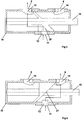
- FIG. 3 shows a sectional view through the housing 19 with the valve body 15 in a first rotational position in which a flow to the outlet port 13 of the exhaust passage 5 is released.
- the valve body 15 has a first exhaust gas guide surface 20 for guiding the flow.
- the outlet opening 14 of the bypass channel 6 is separated from the flow.
- FIG. 4 shows a sectional view through the housing 19 with the valve body 15 in a second rotational position in which the flow through the outlet opening 14 of the bypass channel 6 is released.
- the valve body 15 has a second exhaust guide surface 21.
- the exhaust port 13 of the exhaust passage 5 is separated from the flow.
- FIG. 5 shows the housing 19 with the valve body 15 in a third rotational position, in which the inlet opening 12 of the exhaust gas inlet channel 11 is closed by a base 22 of the valve body 15. At the same time, the outlet openings 13, 14 are separated from each other.
- FIG. 6 shows for clarity the valve body 15 in a perspective view. It can be seen that the base 22 covers a portion of one of the exhaust guide surfaces 20. The other of the exhaust guide surfaces 21 is free and allows an unobstructed flow of the exhaust gas.
Landscapes
- Engineering & Computer Science (AREA)
- General Engineering & Computer Science (AREA)
- Mechanical Engineering (AREA)
- Chemical & Material Sciences (AREA)
- Combustion & Propulsion (AREA)
- Exhaust Silencers (AREA)
- Control Of Throttle Valves Provided In The Intake System Or In The Exhaust System (AREA)
- Exhaust Gas After Treatment (AREA)
- Lift Valve (AREA)
- Exhaust-Gas Circulating Devices (AREA)
- Multiple-Way Valves (AREA)
Abstract
Description
- Die Erfindung betrifft eine Abgassteuerungseinrichtung für eine Brennkraftmaschine mit einem Abgasventil zur Steuerung einer Strömung in einem Abgaskanal und mit einem Bypassventil zur Steuerung einer Strömung in einem Bypasskanal, mit einem ansteuerbaren Aktor zum Ansteuern des Abgasventils und des Bypassventils.
- Solche Abgassteuerungseinrichtungen werden bei heutigen Kraftfahrzeugen häufig eingesetzt und sind aus der Praxis bekannt. Bei der aus der Praxis bekannten Abgassteuerungseinrichtung ist jeweils eine Drosselklappe in dem Bypasskanal und dem Abgaskanal angeordnet. Die im Abgaskanal angeordnete Drosselklappe wird über einen Stellmotor als Aktor angesteuert, während die im Bypasskanal angeordnete Drosselklappe über eine Unterdruckdose verstellt wird. Hierdurch erfordert die Abgassteuerungseinrichtung einen sehr großen baulichen Aufwand.
- Der Erfindung liegt das Problem zugrunde, eine Abgassteuerungseinrichtung der eingangs genannten Art so weiterzubilden, dass sie besonders einfach aufgebaut und kostengünstig zu fertigen ist.
- Dieses Problem wird erfindungsgemäß dadurch gelöst, dass das Abgasventil und das Bypassventil einen gemeinsamen Ventilkörper und einen gemeinsamen Abgaseinlasskanal aufweisen.
- Durch diese Gestaltung weist die Abgassteuerungseinrichtung durch den einzigen Ventilkörper eine besonders geringe Anzahl an Bauteilen auf. Zudem lässt sich der gemeinsame Ventilkörper mit einem einzigen Aktor besonders einfach ansteuern, so dass die Abgassteuerungseinrichtung besonders einfach aufgebaut und kostengünstig zu fertigen ist. Weiterhin hat die erfindungsgemäße Abgassteuerungseinrichtung durch den einzigen Ventilkörper eine besonders geringe Anzahl an Dichtstellen. Die geringe Anzahl an Dichtstellen und die besonders einfache Steuerung der Strömung in dem Abgaskanal und dem Bypasskanal führt zudem zu einer besonders geringen Anzahl an Fehlermöglichkeiten.
- Die Erzeugung des Bypassventils und des Abgasventils mit einem einzelnen Ventilkörper gestaltet sich gemäß einer anderen vorteilhaften Weiterbildung der Erfindung konstruktiv besonders einfach, wenn ein Gehäuse zur Aufnahme des Ventilkörpers eine Einlassöffnung des gemeinsamen Abgaseinlasskanals, eine Auslassöffnung des Abgaskanals des Abgasventils und eine Auslassöffnung des Bypasskanals des Bypassventils aufweist.
- Eine Trennung der Strömungen lässt sich gemäß einer anderen vorteilhaften Weiterbildung der Erfindung vermeiden, wenn der gemeinsame Abgaseinlasskanal bis zu dem gemeinsamen Ventilkörper geführt ist. Hierdurch vermag der Ventilkörper die Strömung im Abgaseinlasskanal in Abhängigkeit von der Ansteuerung des Aktors unmittelbar dem jeweiligen Abgaskanal zuzuleiten.
- Die Abgassteuerungseinrichtung lässt sich gemäß einer anderen vorteilhaften Weiterbildung der Erfindung besonders vielfältig einsetzen, wenn der gemeinsame Ventilkörper in einer Stellung die Einlassöffnung verschließt.
- Ein unerwünschtes Überströmen von Abgas zwischen dem Abgaskanal und dem Bypasskanal lässt sich gemäß einer anderen vorteilhaften Weiterbildung der Erfindung vermeiden, wenn der gemeinsame Ventilkörper in der den gemeinsamen Abgaseinlasskanal verschließenden Stellung die beiden Auslassöffnungen voneinander trennt.
- Der Ventilkörper gestaltet sich gemäß einer anderen vorteilhaften Weiterbildung der Erfindung konstruktiv besonders einfach, wenn der Ventilkörper drehbar in dem Gehäuse angeordnet ist und zwei zur Drehachse geneigte Abgasführungsflächen aufweist, so dass in einer ersten Drehstellung die Einlassöffnung über die eine Abgasführungsfläche mit der einen Auslassöffnung und in der zweiten Drehstellung die Einlassöffnung über die andere Abgasführungsfläche mit der anderen Auslassöffnung verbunden ist. Ein weiterer Vorteil dieser Gestaltung besteht darin, dass der Aktor als einfacher Drehsteller des Ventilkörpers ausgebildet sein kann. Die Abgassteuerungseinrichtung lässt sich hierdurch besonders kostengünstig fertigen.
- Der bauliche Aufwand zum Verschluss der Einlassöffnung lässt sich gemäß einer anderen vorteilhaften Weiterbildung der Erfindung besonders gering halten, wenn der Ventilkörper einen auf einem Teilbereich einer der Abgasführungsflächen angeordneten Sockel hat und wenn in einer dritten Drehstellung der Sockel die Einlassöffnung verschließt.
- Die Störung der Abgasströmung durch eine Drosselung des Sockels lässt sich gemäß einer anderen vorteilhaften Weiterbildung der Erfindung besonders gering halten, wenn der Sockel ausschließlich auf einer der Abgasführungsflächen des Ventilkörpers angeordnet ist. Wenn der Bypasskanal einen geringeren Abgasstrom benötigt als der Abgaskanal, ist der Sockel damit vorzugsweise auf der zu der Auslassöffnung des Bypasskanals führenden Abgasführungsfläche angeordnet.
- Die Ansteuerung des Abgasventils und des Bypassventils gestaltet sich gemäß einer anderen vorteilhaften Weiterbildung der Erfindung konstruktiv besonders einfach, wenn der Aktor ein Stellmotor zur Einstellung der Drehstellung des Ventilkörpers ist.
- Die erfindungsgemäße Abgassteuerungseinrichtung gestaltet sich besonders kompakt, wenn eine Drehachse des Stellmotors parallel zu der Drehachse des Ventilkörpers angeordnet ist und wenn ein Getriebe zwischen Stellmotor und Ventilkörper eben gestaltet ist. Weiterhin wird hierdurch eine thermische Belastung des Stellmotors besonders gering gehalten. Strömungsverluste lassen sich gemäß einer anderen vorteilhaften Weiterbildung der Erfindung besonders gering halten, wenn das Gehäuse rohrförmig mit einer Mantelfläche gestaltet ist und wenn die Einlassöffnung auf einer Seite einer Mantelfläche und die Auslassöffnungen auf der der Einlassöffnung gegenüberliegenden Seite der Mantelfläche angeordnet sind.
- Die Erfindung lässt zahlreiche Ausführungsformen zu. Zur weiteren Verdeutlichung ihres Grundprinzips ist eine davon in der Zeichnung dargestellt und wird nachfolgend beschrieben. Diese zeigt in
- Fig. 1
- schematisch eine Brennkraftmaschine mit einer erfindungsgemäßen Abgassteuerungseinrichtung,
- Fig. 2
- die erfindungsgemäße Abgassteuerungseinrichtung aus
Figur 1 , - Fig. 3 - 5
- Schnittdarstellungen durch einen Teilbereich der erfindungsgemäßen Abgassteuerungseinrichtung in verschiedenen Stellungen,
- Fig. 5
- perspektivisch einen Ventilkörper der erfindungsgemäßen Abgassteuerungseinrichtung.
-
Figur 1 zeigt eine Brennkraftmaschine 1 mit einer Abgassteuerungseinrichtung 2. Die Brennkraftmaschine 1 hat einen Ansaugkanal 3, über den Frischluft aus der Umwelt angesaugt wird, und ein zu der Abgassteuerungseinrichtung 2 führendes Abgasrohr 4. Die Abgassteuerungseinrichtung 2 steuert eine Strömung in einem über nicht dargestellte Schalldämpfer, Filter oder Katalysatoren in die Umwelt führenden Abgaskanal 5 und in einem Bypasskanal 6, der zu einem in dem Ansaugkanal 3 angeordneten Mischer 7 führt. Die Abgassteuerungseinrichtung 2 lässt sich über einen Aktor 8 steuern und hat ein Abgasventil 9 zur Steuerung der Strömung in dem Abgaskanal 5 und ein Bypassventil 10 zur Steuerung der Strömung in dem Bypasskanal 6. Das Abgasrohr 4 der Brennkraftmaschine 1 führt in einen Abgaseinlasskanal 11 der Abgassteuerungseinrichtung 2. -
Figur 2 zeigt die Abgassteuerungseinrichtung 2 ausFigur 1 in einer perspektivischen Darstellung. Die Abgassteuerungseinrichtung 2 hat ein rohrförmiges Gehäuse 19 mit einer Einlassöffnung 12 des Abgaseinlasskanals 11 und einer Auslassöffnung 13 des Abgaskanals 5 des Abgasventils 9 und einer Auslassöffnung 14 des Bypasskanals 6 des Bypassventils 10. Die Auslassöffnungen 13, 14 sind der Einlassöffnung 12 gegenüberliegend in einer Mantelfläche des rohrförmigen Gehäuses 19 angeordnet. Ein einziger Ventilkörper 15 ist drehbar in dem rohrförmigen Gehäuse 19 angeordnet. Der Aktor 8 ist als Stellmotor mit einer parallel zur Drehachse des Ventilkörpers 15 angeordneten Achse ausgebildet und über ein ebenes Getriebe 16 mit dem Ventilkörper 15 verbunden. Zur Vereinfachung sind von dem Getriebe 15 und dem Aktor 8 nur Gehäuseteile 17, 18 dargestellt. -
Figur 3 zeigt eine Schnittdarstellung durch das Gehäuse 19 mit dem Ventilkörper 15 in einer ersten Drehstellung, in der eine Strömung zu der Auslassöffnung 13 des Abgaskanals 5 freigegeben ist. Der Ventilkörper 15 hat hierzu eine erste Abgasführungsfläche 20 zur Führung der Strömung. Die Auslassöffnung 14 des Bypasskanals 6 ist von der Strömung getrennt. -
Figur 4 zeigt eine Schnittdarstellung durch das Gehäuse 19 mit dem Ventilkörper 15 in einer zweiten Drehstellung, in der die Strömung durch die Auslassöffnung 14 des Bypasskanals 6 freigegeben ist. Hierfür hat der Ventilkörper 15 eine zweite Abgasführungsfläche 21. Die Auslassöffnung 13 des Abgaskanals 5 ist von der Strömung getrennt. - Zur Verdeutlichung sind in den
Figuren 1 ,3 und 4 die Strömungen mit Pfeilen gekennzeichnet. -
Figur 5 zeigt das Gehäuse 19 mit dem Ventilkörper 15 in einer dritten Drehstellung, in der die Einlassöffnung 12 des Abgaseinlasskanals 11 durch einen Sockel 22 des Ventilkörpers 15 verschlossen ist. Gleichzeitig sind die Auslassöffnungen 13, 14 voneinander getrennt. -
Figur 6 zeigt zur Verdeutlichung den Ventilkörper 15 in einer perspektivischen Darstellung. Hierbei ist zu erkennen, dass der Sockel 22 einen Teilbereich einer der Abgasführungsflächen 20 verdeckt. Die andere der Abgasführungsflächen 21 ist frei und ermöglicht eine ungehinderte Strömung des Abgases.
Claims (11)
- Abgassteuerungseinrichtung (2) für eine Brennkraftmaschine (1) mit einem Abgasventil (9) zur Steuerung einer Strömung in einem Abgaskanal (5) und mit einem Bypassventil (10) zur Steuerung einer Strömung in einem Bypasskanal (6), mit einem ansteuerbaren Aktor (8) zum Ansteuern des Abgasventils (9) und des Bypassventils (10), dadurch gekennzeichnet, dass das Abgasventil (9) und das Bypassventil (10) einen gemeinsamen Ventilkörper (15) und einen gemeinsamen Abgaseinlasskanal (11) aufweisen.
- Abgassteuerungseinrichtung nach Anspruch 1, dadurch gekennzeichnet, dass ein Gehäuse (19) zur Aufnahme des Ventilkörpers (15) eine Einlassöffnung (12) des gemeinsamen Abgaseinlasskanals (11), eine Auslassöffnung (13) des Abgaskanals (5) des Abgasventils (9) und eine Auslassöffnung (14) des Bypasskanals (6) des Bypassventils (10) aufweist.
- Abgassteuerungseinrichtung nach Anspruch 1 oder 2, dadurch gekennzeichnet, dass der gemeinsame Abgaseinlasskanal (11) bis zu dem gemeinsamen Ventilkörper (15) geführt ist.
- Abgassteuerungseinrichtung nach Anspruch 2 oder 3, dadurch gekennzeichnet, dass der gemeinsame Ventilkörper (15) in einer Stellung die Einlassöffnung (12) verschließt.
- Abgassteuerungseinrichtung nach einem der Ansprüche 2 bis 4, dadurch gekennzeichnet, dass der gemeinsame Ventilkörper (15) in der die Einlassöffnung (12) verschließenden Stellung die beiden Auslassöffnungen (13, 14) voneinander trennt.
- Abgassteuerungseinrichtung nach einem der Ansprüche 2 bis 5, dadurch gekennzeichnet, dass der Ventilkörper (15) drehbar in dem Gehäuse (19) angeordnet ist und zwei zur Drehachse geneigte Abgasführungsflächen (20, 21) aufweist, so dass in einer ersten Drehstellung die Einlassöffnung (12) über die eine Abgasführungsfläche (20) mit der einen Auslassöffnung (13) und in der zweiten Drehstellung die Einlassöffnung (12) über die andere Abgasführungsfläche (21) mit der anderen Auslassöffnung (14) verbunden ist.
- Abgassteuerungseinrichtung nach Anspruch 6, dadurch gekennzeichnet, dass der Ventilkörper (15) einen auf einem Teilbereich einer der Abgasführungsflächen (20, 21) angeordneten Sockel (22) hat und dass in einer dritten Drehstellung der Sockel (22) die Einlassöffnung (12) verschließt.
- Abgassteuerungseinrichtung nach Anspruch 7, dadurch gekennzeichnet, dass der Sockel (22) ausschließlich auf einer der Abgasführungsflächen (20, 21) des Ventilkörpers (15) angeordnet ist.
- Abgassteuerungseinrichtung nach einem der Ansprüche 1 bis 8, dadurch gekennzeichnet, dass der Aktor (8) ein Stellmotor zur Einstellung der Drehstellung des Ventilkörpers (15) ist.
- Abgassteuerungseinrichtung nach Anspruch 9, dadurch gekennzeichnet, dass eine Drehachse des Stellmotors parallel zu der Drehachse des Ventilkörpers (15) angeordnet ist und dass ein Getriebe (16) zwischen Stellmotor und Ventilkörper (15) eben gestaltet ist.
- Abgassteuerungseinrichtung nach einem der Ansprüche 2 bis 10, dadurch gekennzeichnet, dass das Gehäuse (19) rohrförmig mit einer Mantelfläche gestaltet ist und dass die Einlassöffnung (12) auf einer Seite einer Mantelfläche und die Auslassöffnungen (13, 14) auf der der Einlassöffnung (12) gegenüberliegenden Seite der Mantelfläche angeordnet sind.
Priority Applications (6)
| Application Number | Priority Date | Filing Date | Title |
|---|---|---|---|
| EP12464002.0A EP2623765B1 (de) | 2012-02-01 | 2012-02-01 | Abgassteuerungseinrichtung für eine Brennkraftmaschine |
| KR1020147021349A KR102028222B1 (ko) | 2012-02-01 | 2013-01-31 | 내연 기관용 배기가스 제어 장치 |
| JP2014555193A JP6033331B2 (ja) | 2012-02-01 | 2013-01-31 | 内燃機関用の排ガス制御装置 |
| US14/376,075 US9366204B2 (en) | 2012-02-01 | 2013-01-31 | Exhaust-gas control device for an internal combustion engine |
| PCT/EP2013/051858 WO2013113790A1 (de) | 2012-02-01 | 2013-01-31 | Abgassteuerungseinrichtung für eine brennkraftmaschine |
| CN201380007612.7A CN104093965B (zh) | 2012-02-01 | 2013-01-31 | 用于内燃机的废气控制装置 |
Applications Claiming Priority (1)
| Application Number | Priority Date | Filing Date | Title |
|---|---|---|---|
| EP12464002.0A EP2623765B1 (de) | 2012-02-01 | 2012-02-01 | Abgassteuerungseinrichtung für eine Brennkraftmaschine |
Publications (2)
| Publication Number | Publication Date |
|---|---|
| EP2623765A1 true EP2623765A1 (de) | 2013-08-07 |
| EP2623765B1 EP2623765B1 (de) | 2015-04-08 |
Family
ID=47624097
Family Applications (1)
| Application Number | Title | Priority Date | Filing Date |
|---|---|---|---|
| EP12464002.0A Active EP2623765B1 (de) | 2012-02-01 | 2012-02-01 | Abgassteuerungseinrichtung für eine Brennkraftmaschine |
Country Status (6)
| Country | Link |
|---|---|
| US (1) | US9366204B2 (de) |
| EP (1) | EP2623765B1 (de) |
| JP (1) | JP6033331B2 (de) |
| KR (1) | KR102028222B1 (de) |
| CN (1) | CN104093965B (de) |
| WO (1) | WO2013113790A1 (de) |
Families Citing this family (4)
| Publication number | Priority date | Publication date | Assignee | Title |
|---|---|---|---|---|
| CN105972257B (zh) * | 2016-07-20 | 2018-02-09 | 西安航空学院 | 一种增压通气电动阀 |
| US10918569B2 (en) * | 2019-07-15 | 2021-02-16 | Wexco Incorporated | Integrated manifold and valve assembly |
| IT202200024810A1 (it) * | 2022-12-01 | 2024-06-01 | Mv Group S R L | Valvola distributrice ed impianto di filtrazione contenente la medesima |
| CN116025740A (zh) * | 2023-02-23 | 2023-04-28 | 上海捷氢科技股份有限公司 | 一种氢燃料电池及其空气组合阀 |
Citations (8)
| Publication number | Priority date | Publication date | Assignee | Title |
|---|---|---|---|---|
| GB1434078A (en) * | 1973-08-21 | 1976-04-28 | Clark Chapman Ltd | Valve |
| DE10222919A1 (de) * | 2002-05-24 | 2003-12-24 | Man Nutzfahrzeuge Ag | Zweistufig aufgeladene Brennkraftmaschine |
| EP1426604A2 (de) * | 2002-12-06 | 2004-06-09 | Aisan Kogyo Kabushiki Kaisha | Strömungswegumschaltventil |
| FR2879712A1 (fr) * | 2004-12-17 | 2006-06-23 | Renault Sas | Connecteur fluidique pour vehicule automobile a liaison arbre-volet demontable |
| WO2008115773A2 (en) * | 2007-03-20 | 2008-09-25 | Borgwarner Inc. | Combustion engine breathing system valve module |
| US20100116256A1 (en) * | 2007-02-02 | 2010-05-13 | Continental Automatotive Gmbh | Combination Valve |
| EP2236805A2 (de) * | 2009-03-31 | 2010-10-06 | Pierburg GmbH | Klappenventil |
| US20110061625A1 (en) * | 2005-02-07 | 2011-03-17 | Volker Joergl | Exhaust throttle-egr valve module for a diesel engine |
Family Cites Families (10)
| Publication number | Priority date | Publication date | Assignee | Title |
|---|---|---|---|---|
| US4055151A (en) * | 1973-08-21 | 1977-10-25 | Clarke Chapman, Ltd. | Waste heat boiler |
| GB1488705A (en) * | 1974-06-25 | 1977-10-12 | Ici Ltd | Plug valve |
| SE450590B (sv) * | 1982-01-29 | 1987-07-06 | Lars Hedelin | Forbrenningsmotor |
| JPH0420989Y2 (de) * | 1985-01-24 | 1992-05-13 | ||
| DE50311520D1 (de) * | 2002-05-15 | 2009-06-25 | Behr Gmbh & Co Kg | Schaltbarer abgaswaermetauscher |
| JP2007192153A (ja) * | 2006-01-20 | 2007-08-02 | Hino Motors Ltd | Egr装置 |
| EP2418373A1 (de) * | 2010-08-12 | 2012-02-15 | Cooper-Standard Automotive (Deutschland) GmbH | Aktuator und Abgasrückführventil, Wastegate oder variable Turbinengeometrie eines Turboladers mit einem Aktuator |
| US20130269664A1 (en) * | 2012-04-12 | 2013-10-17 | Kamtec Inc. | Exhaust gas recirculation valve and method of manufacturing cam thereof |
| EP2653709A1 (de) * | 2012-04-18 | 2013-10-23 | Continental Automotive GmbH | Mischventil einer Brennkraftmaschine eines Kraftfahrzeuges |
| US9657689B2 (en) * | 2012-05-10 | 2017-05-23 | International Engine Intellectual Property Comapny, LLC. | Modulating bypass valve |
-
2012
- 2012-02-01 EP EP12464002.0A patent/EP2623765B1/de active Active
-
2013
- 2013-01-31 WO PCT/EP2013/051858 patent/WO2013113790A1/de not_active Ceased
- 2013-01-31 CN CN201380007612.7A patent/CN104093965B/zh active Active
- 2013-01-31 KR KR1020147021349A patent/KR102028222B1/ko active Active
- 2013-01-31 US US14/376,075 patent/US9366204B2/en active Active
- 2013-01-31 JP JP2014555193A patent/JP6033331B2/ja active Active
Patent Citations (8)
| Publication number | Priority date | Publication date | Assignee | Title |
|---|---|---|---|---|
| GB1434078A (en) * | 1973-08-21 | 1976-04-28 | Clark Chapman Ltd | Valve |
| DE10222919A1 (de) * | 2002-05-24 | 2003-12-24 | Man Nutzfahrzeuge Ag | Zweistufig aufgeladene Brennkraftmaschine |
| EP1426604A2 (de) * | 2002-12-06 | 2004-06-09 | Aisan Kogyo Kabushiki Kaisha | Strömungswegumschaltventil |
| FR2879712A1 (fr) * | 2004-12-17 | 2006-06-23 | Renault Sas | Connecteur fluidique pour vehicule automobile a liaison arbre-volet demontable |
| US20110061625A1 (en) * | 2005-02-07 | 2011-03-17 | Volker Joergl | Exhaust throttle-egr valve module for a diesel engine |
| US20100116256A1 (en) * | 2007-02-02 | 2010-05-13 | Continental Automatotive Gmbh | Combination Valve |
| WO2008115773A2 (en) * | 2007-03-20 | 2008-09-25 | Borgwarner Inc. | Combustion engine breathing system valve module |
| EP2236805A2 (de) * | 2009-03-31 | 2010-10-06 | Pierburg GmbH | Klappenventil |
Also Published As
| Publication number | Publication date |
|---|---|
| WO2013113790A1 (de) | 2013-08-08 |
| US20140373529A1 (en) | 2014-12-25 |
| CN104093965A (zh) | 2014-10-08 |
| EP2623765B1 (de) | 2015-04-08 |
| JP6033331B2 (ja) | 2016-11-30 |
| KR20140116178A (ko) | 2014-10-01 |
| JP2015505592A (ja) | 2015-02-23 |
| CN104093965B (zh) | 2016-08-24 |
| KR102028222B1 (ko) | 2019-10-02 |
| US9366204B2 (en) | 2016-06-14 |
Similar Documents
| Publication | Publication Date | Title |
|---|---|---|
| EP3012445B1 (de) | Regelvorrichtung für eine verbrennungskraftmaschine | |
| DE112004000677B4 (de) | Auspuff für einen Verbrennungsmotor und Dreiwegeventil für einen solchen Auspuff | |
| EP2623765B1 (de) | Abgassteuerungseinrichtung für eine Brennkraftmaschine | |
| EP2728156A1 (de) | Regelvorrichtung für eine Verbrennungskraftmaschine | |
| EP2820284B1 (de) | Mischventil einer brennkraftmaschine | |
| EP3077645B1 (de) | Drosselklappenstutzen für eine brennkraftmaschine sowie verfahren zur regelung einer drosselklappe in einem drosselklappenstutzen | |
| DE112016006108T5 (de) | Zweiweg-doppelentlüftungssystem und ventilanordnung für turbomotor | |
| DE102008020745A1 (de) | Abgasstromführungseinrichtung und Brennkraftmaschine mit einer Abgasstromführungseinrichtung | |
| WO2013149896A1 (de) | Mischventil einer brennkraftmaschine eines kraftfahrzeuges | |
| EP2662556B1 (de) | Mischventil einer Brennkraftmaschine | |
| DE102012103311B4 (de) | Ventilvorrichtung für eine Verbrennungskraftmaschine | |
| EP2653709A1 (de) | Mischventil einer Brennkraftmaschine eines Kraftfahrzeuges | |
| WO2018091304A1 (de) | Motorradansaugluftführung für einen motorradverbrennungsmotor | |
| DE69607212T2 (de) | Klappenventil für das einlasssystem einer brennkraftmaschine | |
| DE102009057497A1 (de) | Klappenventil zur Einleitung und Steuerung eines Frischluftstromes und eines Abgasrückführstromes | |
| WO2015014660A1 (de) | Einrichtung zur steuerung eines in einem ansaugkanal einer brennkraftmaschine angeordneten ladeluftkühlers und verfahren zum betrieb einer solchen einrichtung | |
| EP3301290B1 (de) | Kanalsystem für eine verbrennungskraftmaschine | |
| DE102005017863A1 (de) | Abgasabführungssystem für eine Brennkraftmaschine sowie Absperrklappe für ein Abgasabführungssystem | |
| DE102011118899A1 (de) | Abgastrakt und Verfahren zum Montieren eines Abgastrakts | |
| EP2843223B1 (de) | Mischventil einer Brennkraftmaschine | |
| EP3121492A1 (de) | Vorrichtung zur gasstromleitung | |
| DE102016200326B4 (de) | Abgas-Rückführ-Kühler | |
| DE2015487C (de) | Vorrichtung zur unterdruckabhängigen Verstellung des Zündzeitpunktes von Brennkraftmaschinen | |
| EP1231375A2 (de) | Abgasrückführsteuerventil für eine Brennkraftmaschine | |
| WO2013160125A1 (de) | Mischventil einer brennkraftmaschine |
Legal Events
| Date | Code | Title | Description |
|---|---|---|---|
| PUAI | Public reference made under article 153(3) epc to a published international application that has entered the european phase |
Free format text: ORIGINAL CODE: 0009012 |
|
| AK | Designated contracting states |
Kind code of ref document: A1 Designated state(s): AL AT BE BG CH CY CZ DE DK EE ES FI FR GB GR HR HU IE IS IT LI LT LU LV MC MK MT NL NO PL PT RO RS SE SI SK SM TR |
|
| AX | Request for extension of the european patent |
Extension state: BA ME |
|
| 17P | Request for examination filed |
Effective date: 20140207 |
|
| RBV | Designated contracting states (corrected) |
Designated state(s): AL AT BE BG CH CY CZ DE DK EE ES FI FR GB GR HR HU IE IS IT LI LT LU LV MC MK MT NL NO PL PT RO RS SE SI SK SM TR |
|
| 17Q | First examination report despatched |
Effective date: 20140403 |
|
| GRAP | Despatch of communication of intention to grant a patent |
Free format text: ORIGINAL CODE: EPIDOSNIGR1 |
|
| INTG | Intention to grant announced |
Effective date: 20140916 |
|
| GRAS | Grant fee paid |
Free format text: ORIGINAL CODE: EPIDOSNIGR3 |
|
| GRAA | (expected) grant |
Free format text: ORIGINAL CODE: 0009210 |
|
| AK | Designated contracting states |
Kind code of ref document: B1 Designated state(s): AL AT BE BG CH CY CZ DE DK EE ES FI FR GB GR HR HU IE IS IT LI LT LU LV MC MK MT NL NO PL PT RO RS SE SI SK SM TR |
|
| REG | Reference to a national code |
Ref country code: GB Ref legal event code: FG4D Free format text: NOT ENGLISH |
|
| REG | Reference to a national code |
Ref country code: CH Ref legal event code: EP |
|
| REG | Reference to a national code |
Ref country code: IE Ref legal event code: FG4D Free format text: LANGUAGE OF EP DOCUMENT: GERMAN |
|
| REG | Reference to a national code |
Ref country code: AT Ref legal event code: REF Ref document number: 720780 Country of ref document: AT Kind code of ref document: T Effective date: 20150515 |
|
| REG | Reference to a national code |
Ref country code: DE Ref legal event code: R096 Ref document number: 502012002777 Country of ref document: DE Effective date: 20150521 |
|
| REG | Reference to a national code |
Ref country code: NL Ref legal event code: VDEP Effective date: 20150408 |
|
| REG | Reference to a national code |
Ref country code: LT Ref legal event code: MG4D |
|
| PG25 | Lapsed in a contracting state [announced via postgrant information from national office to epo] |
Ref country code: NL Free format text: LAPSE BECAUSE OF FAILURE TO SUBMIT A TRANSLATION OF THE DESCRIPTION OR TO PAY THE FEE WITHIN THE PRESCRIBED TIME-LIMIT Effective date: 20150408 |
|
| PG25 | Lapsed in a contracting state [announced via postgrant information from national office to epo] |
Ref country code: LT Free format text: LAPSE BECAUSE OF FAILURE TO SUBMIT A TRANSLATION OF THE DESCRIPTION OR TO PAY THE FEE WITHIN THE PRESCRIBED TIME-LIMIT Effective date: 20150408 Ref country code: PT Free format text: LAPSE BECAUSE OF FAILURE TO SUBMIT A TRANSLATION OF THE DESCRIPTION OR TO PAY THE FEE WITHIN THE PRESCRIBED TIME-LIMIT Effective date: 20150810 Ref country code: FI Free format text: LAPSE BECAUSE OF FAILURE TO SUBMIT A TRANSLATION OF THE DESCRIPTION OR TO PAY THE FEE WITHIN THE PRESCRIBED TIME-LIMIT Effective date: 20150408 Ref country code: NO Free format text: LAPSE BECAUSE OF FAILURE TO SUBMIT A TRANSLATION OF THE DESCRIPTION OR TO PAY THE FEE WITHIN THE PRESCRIBED TIME-LIMIT Effective date: 20150708 Ref country code: HR Free format text: LAPSE BECAUSE OF FAILURE TO SUBMIT A TRANSLATION OF THE DESCRIPTION OR TO PAY THE FEE WITHIN THE PRESCRIBED TIME-LIMIT Effective date: 20150408 Ref country code: ES Free format text: LAPSE BECAUSE OF FAILURE TO SUBMIT A TRANSLATION OF THE DESCRIPTION OR TO PAY THE FEE WITHIN THE PRESCRIBED TIME-LIMIT Effective date: 20150408 |
|
| PG25 | Lapsed in a contracting state [announced via postgrant information from national office to epo] |
Ref country code: IS Free format text: LAPSE BECAUSE OF FAILURE TO SUBMIT A TRANSLATION OF THE DESCRIPTION OR TO PAY THE FEE WITHIN THE PRESCRIBED TIME-LIMIT Effective date: 20150808 Ref country code: LV Free format text: LAPSE BECAUSE OF FAILURE TO SUBMIT A TRANSLATION OF THE DESCRIPTION OR TO PAY THE FEE WITHIN THE PRESCRIBED TIME-LIMIT Effective date: 20150408 Ref country code: GR Free format text: LAPSE BECAUSE OF FAILURE TO SUBMIT A TRANSLATION OF THE DESCRIPTION OR TO PAY THE FEE WITHIN THE PRESCRIBED TIME-LIMIT Effective date: 20150709 Ref country code: RS Free format text: LAPSE BECAUSE OF FAILURE TO SUBMIT A TRANSLATION OF THE DESCRIPTION OR TO PAY THE FEE WITHIN THE PRESCRIBED TIME-LIMIT Effective date: 20150408 |
|
| REG | Reference to a national code |
Ref country code: DE Ref legal event code: R097 Ref document number: 502012002777 Country of ref document: DE |
|
| PG25 | Lapsed in a contracting state [announced via postgrant information from national office to epo] |
Ref country code: EE Free format text: LAPSE BECAUSE OF FAILURE TO SUBMIT A TRANSLATION OF THE DESCRIPTION OR TO PAY THE FEE WITHIN THE PRESCRIBED TIME-LIMIT Effective date: 20150408 Ref country code: DK Free format text: LAPSE BECAUSE OF FAILURE TO SUBMIT A TRANSLATION OF THE DESCRIPTION OR TO PAY THE FEE WITHIN THE PRESCRIBED TIME-LIMIT Effective date: 20150408 |
|
| PLBE | No opposition filed within time limit |
Free format text: ORIGINAL CODE: 0009261 |
|
| STAA | Information on the status of an ep patent application or granted ep patent |
Free format text: STATUS: NO OPPOSITION FILED WITHIN TIME LIMIT |
|
| REG | Reference to a national code |
Ref country code: FR Ref legal event code: PLFP Year of fee payment: 5 |
|
| PG25 | Lapsed in a contracting state [announced via postgrant information from national office to epo] |
Ref country code: PL Free format text: LAPSE BECAUSE OF FAILURE TO SUBMIT A TRANSLATION OF THE DESCRIPTION OR TO PAY THE FEE WITHIN THE PRESCRIBED TIME-LIMIT Effective date: 20150408 Ref country code: SK Free format text: LAPSE BECAUSE OF FAILURE TO SUBMIT A TRANSLATION OF THE DESCRIPTION OR TO PAY THE FEE WITHIN THE PRESCRIBED TIME-LIMIT Effective date: 20150408 Ref country code: RO Free format text: LAPSE BECAUSE OF NON-PAYMENT OF DUE FEES Effective date: 20150408 Ref country code: CZ Free format text: LAPSE BECAUSE OF FAILURE TO SUBMIT A TRANSLATION OF THE DESCRIPTION OR TO PAY THE FEE WITHIN THE PRESCRIBED TIME-LIMIT Effective date: 20150408 |
|
| 26N | No opposition filed |
Effective date: 20160111 |
|
| PG25 | Lapsed in a contracting state [announced via postgrant information from national office to epo] |
Ref country code: SI Free format text: LAPSE BECAUSE OF FAILURE TO SUBMIT A TRANSLATION OF THE DESCRIPTION OR TO PAY THE FEE WITHIN THE PRESCRIBED TIME-LIMIT Effective date: 20150408 Ref country code: BE Free format text: LAPSE BECAUSE OF NON-PAYMENT OF DUE FEES Effective date: 20160229 |
|
| PG25 | Lapsed in a contracting state [announced via postgrant information from national office to epo] |
Ref country code: LU Free format text: LAPSE BECAUSE OF FAILURE TO SUBMIT A TRANSLATION OF THE DESCRIPTION OR TO PAY THE FEE WITHIN THE PRESCRIBED TIME-LIMIT Effective date: 20160201 Ref country code: MC Free format text: LAPSE BECAUSE OF FAILURE TO SUBMIT A TRANSLATION OF THE DESCRIPTION OR TO PAY THE FEE WITHIN THE PRESCRIBED TIME-LIMIT Effective date: 20150408 |
|
| REG | Reference to a national code |
Ref country code: CH Ref legal event code: PL |
|
| GBPC | Gb: european patent ceased through non-payment of renewal fee |
Effective date: 20160201 |
|
| PG25 | Lapsed in a contracting state [announced via postgrant information from national office to epo] |
Ref country code: CH Free format text: LAPSE BECAUSE OF NON-PAYMENT OF DUE FEES Effective date: 20160229 Ref country code: LI Free format text: LAPSE BECAUSE OF NON-PAYMENT OF DUE FEES Effective date: 20160229 |
|
| REG | Reference to a national code |
Ref country code: IE Ref legal event code: MM4A |
|
| PG25 | Lapsed in a contracting state [announced via postgrant information from national office to epo] |
Ref country code: GB Free format text: LAPSE BECAUSE OF NON-PAYMENT OF DUE FEES Effective date: 20160201 Ref country code: IE Free format text: LAPSE BECAUSE OF NON-PAYMENT OF DUE FEES Effective date: 20160201 |
|
| REG | Reference to a national code |
Ref country code: FR Ref legal event code: PLFP Year of fee payment: 6 |
|
| PG25 | Lapsed in a contracting state [announced via postgrant information from national office to epo] |
Ref country code: SE Free format text: LAPSE BECAUSE OF FAILURE TO SUBMIT A TRANSLATION OF THE DESCRIPTION OR TO PAY THE FEE WITHIN THE PRESCRIBED TIME-LIMIT Effective date: 20150408 |
|
| PG25 | Lapsed in a contracting state [announced via postgrant information from national office to epo] |
Ref country code: MT Free format text: LAPSE BECAUSE OF FAILURE TO SUBMIT A TRANSLATION OF THE DESCRIPTION OR TO PAY THE FEE WITHIN THE PRESCRIBED TIME-LIMIT Effective date: 20150408 |
|
| REG | Reference to a national code |
Ref country code: FR Ref legal event code: PLFP Year of fee payment: 7 |
|
| REG | Reference to a national code |
Ref country code: AT Ref legal event code: MM01 Ref document number: 720780 Country of ref document: AT Kind code of ref document: T Effective date: 20170201 |
|
| PG25 | Lapsed in a contracting state [announced via postgrant information from national office to epo] |
Ref country code: AT Free format text: LAPSE BECAUSE OF NON-PAYMENT OF DUE FEES Effective date: 20170201 Ref country code: CY Free format text: LAPSE BECAUSE OF FAILURE TO SUBMIT A TRANSLATION OF THE DESCRIPTION OR TO PAY THE FEE WITHIN THE PRESCRIBED TIME-LIMIT Effective date: 20150408 Ref country code: SM Free format text: LAPSE BECAUSE OF FAILURE TO SUBMIT A TRANSLATION OF THE DESCRIPTION OR TO PAY THE FEE WITHIN THE PRESCRIBED TIME-LIMIT Effective date: 20150408 Ref country code: HU Free format text: LAPSE BECAUSE OF FAILURE TO SUBMIT A TRANSLATION OF THE DESCRIPTION OR TO PAY THE FEE WITHIN THE PRESCRIBED TIME-LIMIT; INVALID AB INITIO Effective date: 20120201 |
|
| PG25 | Lapsed in a contracting state [announced via postgrant information from national office to epo] |
Ref country code: TR Free format text: LAPSE BECAUSE OF FAILURE TO SUBMIT A TRANSLATION OF THE DESCRIPTION OR TO PAY THE FEE WITHIN THE PRESCRIBED TIME-LIMIT Effective date: 20150408 Ref country code: MK Free format text: LAPSE BECAUSE OF FAILURE TO SUBMIT A TRANSLATION OF THE DESCRIPTION OR TO PAY THE FEE WITHIN THE PRESCRIBED TIME-LIMIT Effective date: 20150408 |
|
| PG25 | Lapsed in a contracting state [announced via postgrant information from national office to epo] |
Ref country code: BG Free format text: LAPSE BECAUSE OF FAILURE TO SUBMIT A TRANSLATION OF THE DESCRIPTION OR TO PAY THE FEE WITHIN THE PRESCRIBED TIME-LIMIT Effective date: 20150408 |
|
| PG25 | Lapsed in a contracting state [announced via postgrant information from national office to epo] |
Ref country code: AL Free format text: LAPSE BECAUSE OF FAILURE TO SUBMIT A TRANSLATION OF THE DESCRIPTION OR TO PAY THE FEE WITHIN THE PRESCRIBED TIME-LIMIT Effective date: 20150408 |
|
| REG | Reference to a national code |
Ref country code: DE Ref legal event code: R081 Ref document number: 502012002777 Country of ref document: DE Owner name: VITESCO TECHNOLOGIES GMBH, DE Free format text: FORMER OWNER: CONTINENTAL AUTOMOTIVE GMBH, 30165 HANNOVER, DE |
|
| REG | Reference to a national code |
Ref country code: DE Ref legal event code: R081 Ref document number: 502012002777 Country of ref document: DE Owner name: SCHAEFFLER TECHNOLOGIES AG & CO. KG, DE Free format text: FORMER OWNER: VITESCO TECHNOLOGIES GMBH, 30165 HANNOVER, DE Ref country code: DE Ref legal event code: R081 Ref document number: 502012002777 Country of ref document: DE Owner name: VITESCO TECHNOLOGIES GMBH, DE Free format text: FORMER OWNER: VITESCO TECHNOLOGIES GMBH, 30165 HANNOVER, DE |
|
| REG | Reference to a national code |
Ref country code: DE Ref legal event code: R084 Ref document number: 502012002777 Country of ref document: DE |
|
| P01 | Opt-out of the competence of the unified patent court (upc) registered |
Effective date: 20230530 |
|
| REG | Reference to a national code |
Ref country code: DE Ref legal event code: R081 Ref document number: 502012002777 Country of ref document: DE Owner name: SCHAEFFLER TECHNOLOGIES AG & CO. KG, DE Free format text: FORMER OWNER: VITESCO TECHNOLOGIES GMBH, 93055 REGENSBURG, DE |
|
| PGFP | Annual fee paid to national office [announced via postgrant information from national office to epo] |
Ref country code: DE Payment date: 20250228 Year of fee payment: 14 |
|
| PGFP | Annual fee paid to national office [announced via postgrant information from national office to epo] |
Ref country code: FR Payment date: 20250221 Year of fee payment: 14 |
|
| PGFP | Annual fee paid to national office [announced via postgrant information from national office to epo] |
Ref country code: IT Payment date: 20250224 Year of fee payment: 14 |