EP2623705B1 - Kombinierter bohrhammer - Google Patents
Kombinierter bohrhammer Download PDFInfo
- Publication number
- EP2623705B1 EP2623705B1 EP11827980.1A EP11827980A EP2623705B1 EP 2623705 B1 EP2623705 B1 EP 2623705B1 EP 11827980 A EP11827980 A EP 11827980A EP 2623705 B1 EP2623705 B1 EP 2623705B1
- Authority
- EP
- European Patent Office
- Prior art keywords
- gas
- hole
- impactors
- gas passage
- hole hammer
- Prior art date
- Legal status (The legal status is an assumption and is not a legal conclusion. Google has not performed a legal analysis and makes no representation as to the accuracy of the status listed.)
- Active
Links
Images







Classifications
-
- E—FIXED CONSTRUCTIONS
- E21—EARTH OR ROCK DRILLING; MINING
- E21B—EARTH OR ROCK DRILLING; OBTAINING OIL, GAS, WATER, SOLUBLE OR MELTABLE MATERIALS OR A SLURRY OF MINERALS FROM WELLS
- E21B4/00—Drives for drilling, used in the borehole
- E21B4/06—Down-hole impacting means, e.g. hammers
-
- E—FIXED CONSTRUCTIONS
- E21—EARTH OR ROCK DRILLING; MINING
- E21B—EARTH OR ROCK DRILLING; OBTAINING OIL, GAS, WATER, SOLUBLE OR MELTABLE MATERIALS OR A SLURRY OF MINERALS FROM WELLS
- E21B4/00—Drives for drilling, used in the borehole
- E21B4/16—Plural down-hole drives, e.g. for combined percussion and rotary drilling; Drives for multi-bit drilling units
-
- E—FIXED CONSTRUCTIONS
- E21—EARTH OR ROCK DRILLING; MINING
- E21B—EARTH OR ROCK DRILLING; OBTAINING OIL, GAS, WATER, SOLUBLE OR MELTABLE MATERIALS OR A SLURRY OF MINERALS FROM WELLS
- E21B4/00—Drives for drilling, used in the borehole
- E21B4/06—Down-hole impacting means, e.g. hammers
- E21B4/14—Fluid operated hammers
Definitions
- the disclosure relates to a combined down-the-hole hammer.
- a drill bit is driven by a drill to drill holes on the strata in foundation pile construction, steel reinforcement cages are placed and concrete are filled in the holes subsequently, and foundation piles are formed after the concrete is hardened.
- the drill can hardly drill holes when encountering hard strata, especially rocks and an impactor (also known as a down-the-hole hammer) is needed for impact drilling. Because of the capability of drilling efficiently in hard rocks, the impactor is applied broadly to mining and basic construction of buildings.
- the well-known impactor (published on pages 66 to 68 in the first chapter of China Mining Equipment Manual-Volume One, for example) is also generally called an integrated down-the-hole hammer in the industry, consisting of a conic thread joint 61', an impactor main body 62' including a piston, an impact drill bit 64' provided with a hard alloy head 63', and the diameter of the impactor is generally equal to or smaller than ⁇ 300mm, as shown in Fig. 16 .
- the down-the-hole hammer is connected with the power head of the drill through a hollow drill rod.
- the power head drives the down-the-hole hammer to rotate, compressed air provided by an air compressor enters the impactor main body through the drill rod to drive the piston to strike the drill bit in a reciprocating manner frequently, and the impact energy is transferred to the hard alloy head of the drill bit to strike the rock in a reciprocating manner so as to break the rock.
- the rock fragments are discharged through an annular gap between the drill rod and the pore wall along with the gas discharged by the down-the-hole hammer to form a pile hole eventually.
- the advantage is the highly-efficient drilling in hard strata, especially rocks.
- the integrated down-the-hole hammer has the following shortages when the demands for drilling large-diameter foundation piles ( ⁇ 500 to ⁇ 800 and diameters larger than ⁇ 1000) are increased:
- an American patent US 4429439 publishes another cluster down-the-hole hammer.
- a large-diameter down-the-hole hammer consisting of 5 small-diameter impactors clustered by frames is connected with a drill rod and a gas inlet passage via conic thread joints and distributes compressed air to each small impactors via a transverse gas passage to drive the impactors to perform impact drilling.
- a further document DE 30 24218 A1 is known, disclosing a percussive drilling equipment, the drilling equipment discloses a first drilling linkage, a hammer, low-voltage hammers and a low-floor hammer.
- the the hammer is driven to rotate by a drive motor.
- the low-voltage hammers rotate and drive the impact drill bit to rotate through a spline.
- the disclosure aims at providing a combined down-the-hole hammer to solve at least one of the above problems in the prior art.
- the disclosure provides a combined down-the-hole hammer, comprising a coupler configured to connect with a drill rod and internally provided with a first gas passage; a bracket; and a plurality of impactors installed on the bracket, each of which is provided with a second gas passage and the impact drill bit of each of the impactors can rotate around the axis per se.
- a gas distributor is provided between the coupler and the bracket. The gas distributor is provided with a gas collection chamber communicated with the fist gas passage and a plurality of gas-distributing paths communicating the gas collection chamber with the second gas passage of each of the impactors.
- the impactor comprises: an impactor main body installed in the interior of the bracket, the impactor main body is internally provided with a piston cavity for installing an impact piston; and the impact drill bit installed at the lower end of the piston cavity, the impact drill bit is matched with the impactor main body and is movable axially and rotatable circumferentially.
- the impact drill bit comprises an impact head and a guiding axis connected with each other; the upper portion of the guiding axis is provided with a limiting concave portion extending axially; a limiting ring is sleeved around the limiting concave portion; the guiding axis is inserted into the piston cavity and the limiting ring is limited by a locating platform provided on the inner wall of the piston cavity and a guiding sleeve installed at the lower port of the piston cavity; the guiding sleeve is sleeved on the guiding axis.
- the axis of at least one second gas passage of the impactors is parallel to the axis of the first gas passage; among the gas-distributing paths, the axis of the gas-distributing path which communicates at least one second gas passage and the gas collection chamber is a curve in smooth transition.
- a gas flow regulator is provided on at least one of the gas-distributing paths.
- each of the gas-distributing paths is respectively connected with the top of the corresponding second gas passage through a convergent transition gas hole, and the gas flow distributor is a damper regulating ring provided at each transition gas hole.
- the coupler comprises a columnar connector which forms the first gas passage.
- the drill rod is provided with an installation hole matched with the columnar connector.
- the columnar connector and the drill rod are connected by a pin shaft running therebetween.
- a sealing structure is provided between the columnar connector and the installation hole.
- a rotation stopping platform surface is formed on the outer side wall of the columnar connector and the columnar connector is provided with a first cavity extending horizontally on the outer side wall thereof; the drill rod is provided with a second cavity extending horizontally and intersected with the installation hole.
- the pin shafts are installed in the second cavity and pass through the first cavity.
- the bracket comprises a cylindrical shell, an upper board connected to the upper portion of the cylindrical shell, and a bottom board connected to the lower portion of the cylindrical shell.
- Both the upper board and the bottom board are provided with a locating hole for installing each of the impactors;
- the impactor is provided with a columnar joint at its upper end and the columnar joint is provided with an inner hole forming a portion of the second gas passage.
- the inner hole is connected with the gas-distributing path.
- the columnar joint is provided with a locating circular groove at the periphery thereof. The columnar joint runs through a locating hole of the upper board and is located by a locating ring sleeved on the locating circular groove.
- the locating circular ring is locating ring opened oppositely, and the locating ring is sleeved with limiting sleeves, the upperside of the imiting sleeves (62) is limited by a retainer ring and a snap spring.
- the columnar joint is provided peripherally with a seal groove located above the locating circular groove.
- each of the impactors is matched with the bottom board through a key groove and a connecting key; a dustproof sealing structure is provided between the bottom board and the impactor; the upper port of the cylindrical shell is hermetically matched with the lower end face of the gas distributor, and a transition plate with a hole is provided between the lower end face of the gas distributor and the upper board.
- Fig. 1 to Fig. 6 illustrate the first preferred embodiment of a combined down-the-hole hammer according to the disclosure.
- the combined down-the-hole hammer comprises a coupler 1, a gas distributor 2, a bracket 3 and impactors 4.
- the coupler 1 is used to connect with a drill rod 5 and is internally provided with a first gas passage 10.
- the first gas passage 10 is connected with a gas passage of the drill rod 5.
- the gas distributor 2 is provided between the coupler 1 and the bracket 3.
- Plurality of impactors 4 are installed on the bracket 3 and each of the impactors 4 is individually provided with a second gas passage 40.
- the impactor 4 comprises an impactor main body 42 and an impact drill bit 45.
- the impact drill bit 45 is provided with a hard alloy head 44.
- the gas distributor 2 comprises a gas collection chamber 21 communicated with the fist gas passage 10 and several gas-distributing paths 22 communicating the gas collection chamber 21 with the second gas passage 40 of each of the impactors 4.
- the coupler 1, the gas distributor 2 and the bracket 3 may be connected by the following method.
- the lower end of the coupler 1 is provided with a first flange plate 12 which is connected with the upper end of the gas distributor 2 through a bolt 27 or a screw.
- the lower end of the gas distributor 2 is provided with a second flange plate 24, and the second flange plate 24 is connected with the upper end of the bracket 3 via a bolt 37 or a screw.
- a sealing ring 25 is installed between the coupler 1 and the gas distributor 2.
- FIG. 2 It can be easily seen from Fig. 2 that in the present embodiment, there are 5 impactors 4, one of which is provided in the center and the other four are arranged around the central impactor uniformly in an annular manner.
- the second gas passage of the central impactor 4 is overlapped with the axis of the first gas passage 10, and the axes of the second gas passages of the other impactors 4 are parallel to the axis of the first gas passage 10.
- the gas-distributing path communicating the second gas passage in the center and the collection chamber 21 is a through structure and the axis of the gas-distributing path 22 connecting the four peripheral second gas passages and the collection chamber 21 is a curve in smooth transition, i.e.
- the central gas-distributing path 22 is further provided with a gas flow regulator 26 capable of controlling and regulating the gas supply parameters (including the gas pressure and the gas flow) of the central impactor to effectively improve the utilization efficiency of the compressed air and save the energy.
- a gas flow regulator 26 capable of controlling and regulating the gas supply parameters (including the gas pressure and the gas flow) of the central impactor to effectively improve the utilization efficiency of the compressed air and save the energy.
- the coupler 1 further comprises a columnar connector 11 forming the first gas passage.
- An installation hole 51 matched with the columnar connector is provided on the drill rod 5.
- the columnar connector 11 and the drill rod 5 are connected by a pin shaft 13 running therebetween.
- a sealing structure 14 is provided between the columnar connector 11 and the installation hole 51 so as to install and disassemble the combined down-the-hole hammer and the drill rod 5 conveniently and seal the gas passages reliably, thus overcoming the problems in the prior art that the whole down-the-hole hammer which is connected with the drill rod 5 by a conic thread joint needs to be rotated during the connection and tightened by a very large torque to ensure the tightness between the down-the-hole hammer and the drill rod, and that the onsite installation and disassembly are inconvenient etc.
- the sealing structure 14 is a sealing ring provided at the upper end of the columnar connector 11 and the edge of the upper end of the columnar connector 11 is a chamfered structure so that the gas passage sealing effect is better and the cost is relatively low.
- the cross section of the columnar connector 11 is a regular hexagon.
- the installation hole 51 is an internal hexagonal hole.
- a rotation-stopping platform surface for preventing the columnar connector from rotating relative to the drill rod 5 is formed on each side surface of the columnar connector 11.
- the outer side wall of the columnar connector 11 is provided with a first cavity extending horizontally.
- the drill rod 5 is provided with a second cavity extending horizontally and intersected with the installation hole 51.
- the pin shafts 13 are installed in the second cavity and run through the first cavity to connect the columnar connector 11 and the drill rod 5 and facilitate machining of the installation hole of the pin shafts 13.
- the bracket 3 comprises a cylindrical shell 36, an upper board 35 connected to the upper portion of the cylindrical shell 36 and a bottom board 34 connected to the lower portion of the cylindrical shell 36. Both the upper board 35 and the bottom board 34 are provided with a locating hole for installing each of the impactors 4.
- the upper end of the impactor 4 i.e. the upper end of the impactor main body 42
- the columnar joint 41 is provided with an inner hole forming a portion of the second gas passage.
- the inner hole is connected with the gas-distributing path 22.
- the columnar joint 41 is provided peripherally with a locating circular groove.
- the columnar joint 41 runs through a locating hole 35 of the upper board and is located by a locating ring 61 sleeved on the locating circular groove. To ensure the gas tightness of the gas passage, the end of the columnar joint 41 is installed with a sealing ring 9.
- the upper port of the cylindrical shell 36 is hermetically matched with the lower end face of the gas distributor 2, and a transition plate 31 with a hole is provided between the lower end face of the gas distributor 2 and the upper board 35.
- the locating ring 61 is located in the hole on the transition plate 31 to enhance the structural stability of the combined down-the-hole hammer.
- each of the impactors 4 is matched with the bottom board 34 through a key groove 32 and a connecting key 43.
- a dustproof sealing structure 33 is provided between the bottom board 34 and the impactor 4.
- the dustproof sealing structure 33 is a dustproof ring extending into the locating hole of the bottom board 34, for example.
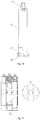
- Fig. 7 to Fig. 9 show the second preferred embodiment of the disclosure.
- the difference between the second preferred embodiment and the first preferred embodiment above is that there are six impactors 4.
- the axiss of the second gas passages 40 of the six impactors 4 are all parallel with the first gas passage 10.
- the gas-distributing path 22 connecting the collection chamber 21 with the second gas passage 40 of each of the impactors is a large curvature gas passage structure.
- each gas-distributing path 22 is respectively connected with the top of the corresponding second gas passage 40 through a convergent transition gas hole 20, and the gas flow distributor 26 is a damper regulating ring provided at each transition gas hole 20.
- damper regulating rings of different specifications can be selected as the gas flow distributor 26 of each corresponding gas-distributing path 22 according to the working pressure of each of the impactors 4 to distribute gas flows reasonably, utilize the energy efficiently and further improve the drilling efficiency.
- the impactor 4 comprises an impactor main body 42 and the impact drill bit 45.
- the impactor main body 42 is installed in the bracket 3 and the impactor main body 42 is internally provided with a piston cavity for installing an impact piston 410.
- the impact drill bit 45 is installed in the piston cavity from the lower end, and the impact drill bit 45 and the impactor main body 42 can be matched in an axial moving manner or a circumferential rotating manner.
- the impact drill bit 45 of each of the impactors 4 can rotate around the axis per se while revolving with the impactor so that the hard alloy head 44 on the impact drill bit 45 is abraded uniformly to improve the working efficiency and prolong the service life.
- the impact drill bit 45 comprises an impact head 451 a guiding axis 49 connected with each other.
- the hard alloy head 44 is installed on the impact head 451.
- the upper portion of the guiding axis 49 is provided with a limiting concave portion 401 extending axially.
- a limiting ring 48 is sleeved on the limiting concave portion 401.
- the guiding axis 49 is inserted into the piston cavity from the lower end and the limiting ring 48 is limited by a locating platform provided on the inner wall of the piston cavity and a guiding sleeve 47 installed at the lower port of the piston cavity.
- the guiding sleeve 47 is sleeved on the guiding axis 49.
- the limiting ring 48 comprises limiting rings opened oppositely.
- the locating ring 61 installed in the locating circular groove 411 of the columnar joint 41 is locating ring opened oppositely.
- Limiting sleeves 62 are further sleeved out of the limiting rings 61 and the upperside of the limiting sleeves 62 are limited by a retainer ring 63 and a snap spring 64.
- the columnar joint 41 is provided peripherally with a seal groove 412 and the seal groove 412 is located above the locating circular groove 410 to ensure that gas passage tightness.
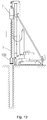
- a construction method of a combined down-the-hole hammer according to the disclosure will be illustrated below in combination with Fig. 10 to Fig. 15 .
- a hollow screw drill rod 5 can be also used in Step 1.
- Step 2 before fixedly splicing the combined down-the-hole hammer 100 and the columnar drill rod 5 by two pin shafts 13 and a sealing ring 14, a gas flow regulator 26 in a gas collection chamber 21 of the combined down-the-hole hammer 100 can be regulated to a set value according to the output rotating speed of the power head 7 of the drill and the parameters of the gas supply system 8 of the drill so that flows can be distributed reasonably, thus utilizing the energy efficiently and improving the drilling efficiency.
- the combined down-the-hole hammer according to the disclosure is matched with a screw drill rod so as to achieve better discharge effect, higher construction efficiency and higher economical efficiency, and drill deeper holes in the condition of the same gas supply amount.
- the combined down-the-hole hammer is especially applicable to hard strata, especially rocks to construct large-diameter ( ⁇ 500 to ⁇ 800 and diameters larger than ⁇ 1000) foundation piles efficiently.
- the disclosure provides a combined down-the-hole hammer with low cost, rational structure, easy maintenance, convenient installation and disassembly, reliable seal, efficient energy utilization and high drilling efficiency.
Landscapes
- Engineering & Computer Science (AREA)
- Life Sciences & Earth Sciences (AREA)
- Geology (AREA)
- Mining & Mineral Resources (AREA)
- Mechanical Engineering (AREA)
- Physics & Mathematics (AREA)
- Environmental & Geological Engineering (AREA)
- Fluid Mechanics (AREA)
- General Life Sciences & Earth Sciences (AREA)
- Geochemistry & Mineralogy (AREA)
- Earth Drilling (AREA)
Claims (9)
- Kombinierter Imlochhammer, dadurch gekennzeichnet, dass, der Hammer Folgendes umfasst:einen Koppler (1), der mit einer Bohrstange (5) verbunden ist und innen mit einem ersten Gasdurchgang (10) versehen ist;eine Halterung (3);eine Mehrheit von Impaktoren (4), die auf der Halterung (3) montiert sind, wobei jeder Impaktor (4) mit einem zweiten Gasdurchgang (40) versehen ist; wobei, wenn der kombinierte Imlochhammer zur Drehung und Bohrung durch den Antriebskopf angetrieben wird, ein Schlagbohrmeißel (45) von jedem der Impaktoren (4) um seine Achse drehbar ist;einen Gasverteiler (2), der zwischen dem Koppler (1) und der Halterung (3) vorgesehen ist; der Gasverteiler (2) ist mit einer Gassammelkammer (21), die mit dem ersten Gasdurchgang (10) in Kommunikation steht, und einer Mehrheit von Gasverteilungswegen (22), die die Gassammelkammer (21) mit dem zweiten Gasdurchgang (40) jedes Impaktors (4) verbinden, versehen;der Koppler (1) umfasst einen Säulenverbinder (11), der den ersten Gasdurchgang bildet; die Bohrstange (5) ist mit einem Installationsloch (51) versehen, das mit dem Säulenverbinder zusammenpasst; der Säulenverbinder (11) und die Bohrstange (5) sind durch einen dazwischen laufenden Stiftschaft (13) verbunden; eine Dichtungsstruktur (14) ist zwischen dem Säulenverbinder (11) und dem Installationsloch (51) vorgesehen;jeder Impaktor (4) umfasst: einen Impaktorhauptkörper (42), der im Inneren der Halterung (3) installiert ist, wobei der Impaktorhauptkörper (42) innen mit einem Kolbenhohlraum zum Installieren eines Schlagkolbens (410) versehen ist; und einen Schlagbohrmeißel (45), der am unteren Ende des Kolbenhohlraums installiert ist, wobei der Schlagbohrmeißel (45) mit dem Impaktorhauptkörper (42) zusammenpasst und umlaufend axial und drehbar beweglich ist;der Schlagbohrmeißel (45) umfasst einen Schlagkopf (451) und eine Führungsachse (49), die miteinander verbunden sind;der obere Teil der Führungsachse (49) ist mit einem konkaven Begrenzungsteil (401) versehen, der sich axial erstreckt; ein Begrenzungsring (48) umgibt den konkaven Begrenzungsteil (401);die Führungsachse (49) ist in den Kolbenhohlraum eingeführt und der Begrenzungsring (48) ist durch eine Positionierungsplattform begrenzt, die an der Innenwand des Kolbenhohlraums vorgesehen ist und eine Führungshülse (47) ist am unteren Eingang des Kolbenhohlraums installiert;die Führungshülse (47) ist umgebend auf die Führungsachse (49) aufgesetzt.
- Kombinierter Imlochhammer nach Anspruch 1, dadurch gekennzeichnet, dass
die Achse mindestens eines zweiten Gasdurchgangs (40) der Impaktoren (4) zur Achse des ersten Gasdurchgangs (10) parallel ist; unter den Gasverteilungswegen (22), der Achse des Gasverteilungswegs, der mit mindestens einem zweiten Gasdurchgang in Kommunikation steht, und der Gassammelkammer ist eine Kurve in fließendem Übergang. - Kombinierter Imlochhammer nach Anspruch 1, dadurch gekennzeichnet, dass ein Gasdurchflussregler (26) auf mindestens einem der Gasverteilungswege (22) vorgesehen ist.
- Kombinierter Imlochhammer nach Anspruch 3, dadurch gekennzeichnet, dass jeder der Gasverteilungswege (22) jeweils mit dem oberen Ende des entsprechenden zweiten Gasdurchgangs (40) durch ein konvergierendes Übergangsgasloch (20) verbunden ist, und der Gasdurchflussverteiler (26) ein Dämpferregelring ist, der am Übergangsgasloch (20) vorgesehen ist.
- Kombinierter Imlochhammer nach Anspruch 1, dadurch gekennzeichnet, dass
mindestens zwei Stiftschäfte (13) vorgesehen sind;
eine drehungsanhaltende Plattformsoberfläche an der äußeren Seitenwand des Säulenverbinders (11) gebildet ist;
der Säulenverbinder (11) mit einem ersten Hohlraum versehen ist, der sich horizontal auf der äußeren Seitenwand davon erstreckt; die Bohrstange (5) mit einem zweiten Hohlraum versehen ist, der sich horizontal erstreckt und das Installationsloch (51) kreuzt; die Stiftschäfte (13) im zweiten Hohlraum installiert sind und durch den ersten Hohlraum durchgehen. - Kombinierter Imlochhammer nach Anspruch 1, dadurch gekennzeichnet, dass
die Halterung (3) eine zylindrische Schale (36), eine obere Platte (35), die mit dem oberen Teil der zylindrischen Schale (36) verbunden ist, und eine untere Platte (34), die mit dem unteren Teil der zylindrischen Schale (36) verbunden ist, umfasst; wobei sowohl die obere Platte (35) als auch die untere Platte (34) mit einem Positionierungsloch zur Installation jedes der Impaktoren (4) versehen sind;
jeder Impaktor (4) mit einem Säulengelenk (41) am oberen Ende versehen ist und das Säulengelenk (41) mit einem inneren Loch versehen ist, das ein Teil des zweiten Gasdurchgangs bildet; wobei das innere Loch mit dem Gasverteilungsweg (22) verbunden ist; das Säulengelenk (41) mit einer kreisförmigen Positionierungsnut (411) am Umfang davon verbunden ist; das Säulengelenk (41) durch ein Positionierungsloch der oberen Platte (35) läuft und an einem Positionierungsring (61) angeordnet ist, der umgebend auf die kreisförmige Positionierungsnut (411) aufgesetzt ist. - Kombinierter Imlochhammer nach Anspruch 6, dadurch gekennzeichnet, dass der Positionierungsring (61) ein Positionierungsring ist, der entgegengesetzt offen ist, und der Positionierungsring (61) von Begrenzungshülsen (62) umgeben ist, wobei die obere Seite der Begrenzungshülsen (62) durch einen Haltering (63) und eine Schnappfeder (64) begrenzt ist.
- Kombinierter Imlochhammer nach Anspruch 7, dadurch gekennzeichnet, dass das Säulengelenk (41) peripher mit einer Dichtungsnut (412) versehen ist und die Dichtungsnut (412) oberhalb der kreisförmigen Positionierungsnut (410) angeordnet ist.
- Kombinierter Imlochhammer nach Anspruch 8, dadurch gekennzeichnet, dass
jeder der Impaktoren (4) mit der unteren Platte (34) durch eine Passfedernut (32) und eine Verbindungspassfeder (43) zusammenpasst;
eine staubdichte Dichtungsstruktur (33) zwischen der unteren Platte (34) und dem Impaktor (4) vorgesehen ist;
der obere Eingang der zylindrischen Schale (36) mit der unteren Endfläche des Gasverteilers (2) hermetisch zusammenpasst, und eine Übergangsplatte (31) mit einem Loch zwischen der unteren Endfläche des Gasverteilers (2) und der oberen Platte (35) vorgesehen ist.
Applications Claiming Priority (6)
| Application Number | Priority Date | Filing Date | Title |
|---|---|---|---|
| CN 201010298838 CN101949261B (zh) | 2010-09-30 | 2010-09-30 | 组合式潜孔锤及其施工方法 |
| CN 201020550979 CN201786251U (zh) | 2010-09-30 | 2010-09-30 | 一种组合式潜孔锤 |
| CN 201020550973 CN201786250U (zh) | 2010-09-30 | 2010-09-30 | 组合式潜孔锤 |
| CN 201020550985 CN201786252U (zh) | 2010-09-30 | 2010-09-30 | 一种自公转组合式潜孔锤 |
| CN 201010298875 CN101967955B (zh) | 2010-09-30 | 2010-09-30 | 一种自公转组合式潜孔锤及其施工方法 |
| PCT/CN2011/076226 WO2012041084A1 (zh) | 2010-09-30 | 2011-06-23 | 组合式潜孔锤 |
Publications (3)
| Publication Number | Publication Date |
|---|---|
| EP2623705A1 EP2623705A1 (de) | 2013-08-07 |
| EP2623705A4 EP2623705A4 (de) | 2017-04-19 |
| EP2623705B1 true EP2623705B1 (de) | 2019-10-16 |
Family
ID=45891886
Family Applications (1)
| Application Number | Title | Priority Date | Filing Date |
|---|---|---|---|
| EP11827980.1A Active EP2623705B1 (de) | 2010-09-30 | 2011-06-23 | Kombinierter bohrhammer |
Country Status (4)
| Country | Link |
|---|---|
| EP (1) | EP2623705B1 (de) |
| JP (1) | JP5948333B2 (de) |
| KR (1) | KR101746822B1 (de) |
| WO (1) | WO2012041084A1 (de) |
Families Citing this family (19)
| Publication number | Priority date | Publication date | Assignee | Title |
|---|---|---|---|---|
| KR101460435B1 (ko) * | 2013-03-26 | 2014-11-12 | (주)동우기계 | 지반 굴착 장치 |
| CN103790513B (zh) * | 2014-03-03 | 2016-02-24 | 北京南车时代机车车辆机械有限公司 | 气动潜孔锤排渣装置 |
| US9657521B2 (en) * | 2014-06-02 | 2017-05-23 | King Fahd University Of Petroleum And Minerals | Directional system drilling and method |
| US11174684B2 (en) | 2020-02-26 | 2021-11-16 | Caterpillar Global Mining Equipment Llc | Flushing system in drill bits |
| CN111270991A (zh) * | 2020-04-13 | 2020-06-12 | 北京中岩大地科技股份有限公司 | 一种变幅式潜孔锤钻机及其施工方法 |
| CN111502532B (zh) * | 2020-06-01 | 2024-10-22 | 吉林大学 | 开采干热岩地热能的沉浸式气动潜孔锤钻进装置及方法 |
| CN111594039B (zh) * | 2020-06-30 | 2024-10-08 | 吉林大学 | 一种大直径组合式空气反循环潜孔锤 |
| CN112196460B (zh) * | 2020-09-08 | 2023-10-27 | 李新形 | 一种地下连续墙潜孔锤成槽机及其使用方法 |
| CN112227941B (zh) * | 2020-11-02 | 2024-12-06 | 新泰玖翊工程机械有限公司 | 一种可靠性集束式潜孔锤子锤及其固定方法 |
| CN113431485B (zh) * | 2021-01-21 | 2025-01-10 | 南京工业职业技术大学 | 一种集束式潜孔锤 |
| CN113669002B (zh) * | 2021-08-03 | 2023-12-08 | 深圳宏业基岩土科技股份有限公司 | 大直径灌注桩坚硬岩层组合式成孔施工方法 |
| KR102607022B1 (ko) * | 2021-10-19 | 2023-11-29 | 창신인터내셔날 주식회사 | 에어서플라이 모듈이 조립된 조합해머 |
| CN114482864B (zh) * | 2021-12-24 | 2024-12-06 | 中建东设岩土工程有限公司 | 一种气动旋挖钻机使用的双壁钻头 |
| CN114856412B (zh) * | 2022-04-21 | 2025-08-08 | 江西东锐智能装备科技股份有限公司 | 一种飞翼液压冲击器 |
| KR102673470B1 (ko) * | 2022-07-20 | 2024-06-10 | 창신인터내셔날 주식회사 | DTH Hammer의 혼합유체 분리시스템 |
| CN115788280B (zh) * | 2022-11-18 | 2023-09-26 | 浩洲钻科工程机械(山东)有限公司 | 独立式多通道全孔反循环集束式潜孔锤 |
| CN117145378B (zh) * | 2023-10-25 | 2024-02-02 | 长沙黑金刚实业有限公司 | 一种反循环冲击器 |
| CN118601471B (zh) * | 2024-08-09 | 2024-11-29 | 张家口市宣化金科钻孔机械有限公司 | 一种具有钻孔和测深功能的潜孔钻机 |
| CN118958856B (zh) * | 2024-08-26 | 2025-10-17 | 国网福建省电力有限公司 | 一种集束式冲击器 |
Citations (4)
| Publication number | Priority date | Publication date | Assignee | Title |
|---|---|---|---|---|
| JPH05287975A (ja) * | 1992-04-03 | 1993-11-02 | Koken Kogyo Kk | ダウンザホールドリルを使用するロータリテーブル型ボーリング機 |
| JPH0813974A (ja) * | 1994-06-28 | 1996-01-16 | Kencho Kobe:Kk | 地下穿孔機用スクリューロッドの接続構造 |
| JPH08312278A (ja) * | 1995-05-17 | 1996-11-26 | Koken Boring Mach Co Ltd | 二重管掘削システム |
| EP0851090A1 (de) * | 1996-06-19 | 1998-07-01 | Suntech Corporation | Im-loch bohrhammer |
Family Cites Families (12)
| Publication number | Priority date | Publication date | Assignee | Title |
|---|---|---|---|---|
| DE3024218C2 (de) * | 1980-06-27 | 1982-09-16 | Hydroc Gesteinsbohrtechnik GmbH, 5960 Olpe | Schlag-Bohreinrichtungen für Großlochbohrungen |
| SU1348478A1 (ru) * | 1984-03-19 | 1987-10-30 | В. А. Вареник, В. Ф. Жданков и М. Н. Чучвич | Способ бурени скважин ударными импульсами |
| CN85102035B (zh) * | 1985-04-01 | 1988-04-13 | 武汉钢铁公司 | 具有两种排渣方式的潜孔钻具 |
| CN85204565U (zh) * | 1985-10-26 | 1987-04-29 | 唐山工程技术学院 | 组合供气式潜孔风动冲击器 |
| US5267622A (en) * | 1992-06-22 | 1993-12-07 | Fletcher Gerald L | Impact block assembly for percussion drilling apparatus |
| FR2713276B1 (fr) * | 1993-12-03 | 1996-02-09 | Andre Boniface | Outil de forage à percussion et à double rotation pour forage de grand diamètre. |
| JPH09158645A (ja) * | 1995-12-08 | 1997-06-17 | Yubiron Fuakuto:Kk | 掘削装置における軸部連結装置 |
| US5735358A (en) * | 1996-06-06 | 1998-04-07 | Ingersoll-Rand Company | Indexing percussive drilling bit |
| JP4167115B2 (ja) * | 2003-05-01 | 2008-10-15 | 鉱研工業株式会社 | リトラクトビット装置 |
| JP4076554B2 (ja) * | 2005-11-25 | 2008-04-16 | 一功 古木 | 掘削装置、掘削装置を備えた回転式掘削機及び地中掘削工法 |
| JP4076564B1 (ja) * | 2006-12-04 | 2008-04-16 | 一功 古木 | 地中掘削用の掘削装置、回転式掘削機及び地中掘削工法 |
| CN201428375Y (zh) * | 2009-06-24 | 2010-03-24 | 北京市三一重机有限公司 | 气动冲击锤 |
-
2011
- 2011-06-23 KR KR1020137011112A patent/KR101746822B1/ko active Active
- 2011-06-23 WO PCT/CN2011/076226 patent/WO2012041084A1/zh not_active Ceased
- 2011-06-23 EP EP11827980.1A patent/EP2623705B1/de active Active
- 2011-06-23 JP JP2013530541A patent/JP5948333B2/ja active Active
Patent Citations (4)
| Publication number | Priority date | Publication date | Assignee | Title |
|---|---|---|---|---|
| JPH05287975A (ja) * | 1992-04-03 | 1993-11-02 | Koken Kogyo Kk | ダウンザホールドリルを使用するロータリテーブル型ボーリング機 |
| JPH0813974A (ja) * | 1994-06-28 | 1996-01-16 | Kencho Kobe:Kk | 地下穿孔機用スクリューロッドの接続構造 |
| JPH08312278A (ja) * | 1995-05-17 | 1996-11-26 | Koken Boring Mach Co Ltd | 二重管掘削システム |
| EP0851090A1 (de) * | 1996-06-19 | 1998-07-01 | Suntech Corporation | Im-loch bohrhammer |
Also Published As
| Publication number | Publication date |
|---|---|
| JP2013538957A (ja) | 2013-10-17 |
| KR101746822B1 (ko) | 2017-06-13 |
| EP2623705A4 (de) | 2017-04-19 |
| EP2623705A1 (de) | 2013-08-07 |
| WO2012041084A1 (zh) | 2012-04-05 |
| JP5948333B2 (ja) | 2016-07-06 |
| KR20130110175A (ko) | 2013-10-08 |
Similar Documents
| Publication | Publication Date | Title |
|---|---|---|
| EP2623705A1 (de) | Kombinierter bohrhammer | |
| CN101967955B (zh) | 一种自公转组合式潜孔锤及其施工方法 | |
| CN101949261B (zh) | 组合式潜孔锤及其施工方法 | |
| CN111119726B (zh) | 一种环形集束式潜孔锤 | |
| CN201786252U (zh) | 一种自公转组合式潜孔锤 | |
| CN105003199B (zh) | 一种大直径桩孔作业工法 | |
| CN111594039B (zh) | 一种大直径组合式空气反循环潜孔锤 | |
| CN108672029A (zh) | 一种新型立式搅拌磨 | |
| AU713748B2 (en) | Hydraulic drive for rotation of a rock drill | |
| CN107956419A (zh) | 一种振击器 | |
| CN112696149A (zh) | 潜孔取芯锤头及环形潜孔锤 | |
| CN105822220A (zh) | 一种液压凿岩机 | |
| CN201786251U (zh) | 一种组合式潜孔锤 | |
| CN204728997U (zh) | 液压回转钻机潜孔破碎入岩钻 | |
| CN113356753A (zh) | 一种组合式可变口径集束式潜孔锤 | |
| CN203669735U (zh) | 一种复合动力桩工钻机 | |
| CN212689910U (zh) | 一种大直径组合式空气反循环潜孔锤 | |
| CN210460490U (zh) | 一种高频周向冲击式螺杆钻具结构 | |
| CN104695882A (zh) | 一种气动潜孔锤三通道多功能水龙头 | |
| CA2516507C (en) | Sleeve piston fluid motor | |
| CN204899815U (zh) | 气动潜孔锤三通道多功能水龙头 | |
| CN112431547B (zh) | 交叉接头及潜孔钻进装置 | |
| CN216665527U (zh) | 一种气动旋挖钻机使用的中间过气提引器 | |
| CN201786250U (zh) | 组合式潜孔锤 | |
| CN213775231U (zh) | 交叉接头及潜孔钻进装置 |
Legal Events
| Date | Code | Title | Description |
|---|---|---|---|
| PUAI | Public reference made under article 153(3) epc to a published international application that has entered the european phase |
Free format text: ORIGINAL CODE: 0009012 |
|
| 17P | Request for examination filed |
Effective date: 20130430 |
|
| AK | Designated contracting states |
Kind code of ref document: A1 Designated state(s): AL AT BE BG CH CY CZ DE DK EE ES FI FR GB GR HR HU IE IS IT LI LT LU LV MC MK MT NL NO PL PT RO RS SE SI SK SM TR |
|
| DAX | Request for extension of the european patent (deleted) | ||
| REG | Reference to a national code |
Ref country code: DE Ref legal event code: R079 Ref document number: 602011062807 Country of ref document: DE Free format text: PREVIOUS MAIN CLASS: E21B0004060000 Ipc: E21B0004140000 |
|
| RA4 | Supplementary search report drawn up and despatched (corrected) |
Effective date: 20170317 |
|
| RIC1 | Information provided on ipc code assigned before grant |
Ipc: E21B 4/14 20060101AFI20170313BHEP Ipc: E21B 4/16 20060101ALI20170313BHEP |
|
| STAA | Information on the status of an ep patent application or granted ep patent |
Free format text: STATUS: EXAMINATION IS IN PROGRESS |
|
| 17Q | First examination report despatched |
Effective date: 20180126 |
|
| GRAP | Despatch of communication of intention to grant a patent |
Free format text: ORIGINAL CODE: EPIDOSNIGR1 |
|
| STAA | Information on the status of an ep patent application or granted ep patent |
Free format text: STATUS: GRANT OF PATENT IS INTENDED |
|
| INTG | Intention to grant announced |
Effective date: 20190624 |
|
| GRAS | Grant fee paid |
Free format text: ORIGINAL CODE: EPIDOSNIGR3 |
|
| GRAA | (expected) grant |
Free format text: ORIGINAL CODE: 0009210 |
|
| STAA | Information on the status of an ep patent application or granted ep patent |
Free format text: STATUS: THE PATENT HAS BEEN GRANTED |
|
| AK | Designated contracting states |
Kind code of ref document: B1 Designated state(s): AL AT BE BG CH CY CZ DE DK EE ES FI FR GB GR HR HU IE IS IT LI LT LU LV MC MK MT NL NO PL PT RO RS SE SI SK SM TR |
|
| REG | Reference to a national code |
Ref country code: GB Ref legal event code: FG4D |
|
| REG | Reference to a national code |
Ref country code: CH Ref legal event code: EP |
|
| REG | Reference to a national code |
Ref country code: DE Ref legal event code: R096 Ref document number: 602011062807 Country of ref document: DE |
|
| REG | Reference to a national code |
Ref country code: IE Ref legal event code: FG4D |
|
| REG | Reference to a national code |
Ref country code: AT Ref legal event code: REF Ref document number: 1191421 Country of ref document: AT Kind code of ref document: T Effective date: 20191115 |
|
| REG | Reference to a national code |
Ref country code: DE Ref legal event code: R082 Ref document number: 602011062807 Country of ref document: DE Representative=s name: STRAUS, ALEXANDER, DIPL.-CHEM.UNIV. DR.PHIL., DE Ref country code: DE Ref legal event code: R082 Ref document number: 602011062807 Country of ref document: DE Representative=s name: 2K PATENT- UND RECHTSANWAELTE PARTNERSCHAFT MB, DE |
|
| REG | Reference to a national code |
Ref country code: SE Ref legal event code: TRGR |
|
| REG | Reference to a national code |
Ref country code: NL Ref legal event code: MP Effective date: 20191016 |
|
| REG | Reference to a national code |
Ref country code: LT Ref legal event code: MG4D |
|
| REG | Reference to a national code |
Ref country code: AT Ref legal event code: MK05 Ref document number: 1191421 Country of ref document: AT Kind code of ref document: T Effective date: 20191016 |
|
| PG25 | Lapsed in a contracting state [announced via postgrant information from national office to epo] |
Ref country code: PT Free format text: LAPSE BECAUSE OF FAILURE TO SUBMIT A TRANSLATION OF THE DESCRIPTION OR TO PAY THE FEE WITHIN THE PRESCRIBED TIME-LIMIT Effective date: 20200217 Ref country code: NO Free format text: LAPSE BECAUSE OF FAILURE TO SUBMIT A TRANSLATION OF THE DESCRIPTION OR TO PAY THE FEE WITHIN THE PRESCRIBED TIME-LIMIT Effective date: 20200116 Ref country code: GR Free format text: LAPSE BECAUSE OF FAILURE TO SUBMIT A TRANSLATION OF THE DESCRIPTION OR TO PAY THE FEE WITHIN THE PRESCRIBED TIME-LIMIT Effective date: 20200117 Ref country code: PL Free format text: LAPSE BECAUSE OF FAILURE TO SUBMIT A TRANSLATION OF THE DESCRIPTION OR TO PAY THE FEE WITHIN THE PRESCRIBED TIME-LIMIT Effective date: 20191016 Ref country code: LT Free format text: LAPSE BECAUSE OF FAILURE TO SUBMIT A TRANSLATION OF THE DESCRIPTION OR TO PAY THE FEE WITHIN THE PRESCRIBED TIME-LIMIT Effective date: 20191016 Ref country code: ES Free format text: LAPSE BECAUSE OF FAILURE TO SUBMIT A TRANSLATION OF THE DESCRIPTION OR TO PAY THE FEE WITHIN THE PRESCRIBED TIME-LIMIT Effective date: 20191016 Ref country code: LV Free format text: LAPSE BECAUSE OF FAILURE TO SUBMIT A TRANSLATION OF THE DESCRIPTION OR TO PAY THE FEE WITHIN THE PRESCRIBED TIME-LIMIT Effective date: 20191016 Ref country code: AT Free format text: LAPSE BECAUSE OF FAILURE TO SUBMIT A TRANSLATION OF THE DESCRIPTION OR TO PAY THE FEE WITHIN THE PRESCRIBED TIME-LIMIT Effective date: 20191016 Ref country code: NL Free format text: LAPSE BECAUSE OF FAILURE TO SUBMIT A TRANSLATION OF THE DESCRIPTION OR TO PAY THE FEE WITHIN THE PRESCRIBED TIME-LIMIT Effective date: 20191016 Ref country code: BG Free format text: LAPSE BECAUSE OF FAILURE TO SUBMIT A TRANSLATION OF THE DESCRIPTION OR TO PAY THE FEE WITHIN THE PRESCRIBED TIME-LIMIT Effective date: 20200116 |
|
| PG25 | Lapsed in a contracting state [announced via postgrant information from national office to epo] |
Ref country code: IS Free format text: LAPSE BECAUSE OF FAILURE TO SUBMIT A TRANSLATION OF THE DESCRIPTION OR TO PAY THE FEE WITHIN THE PRESCRIBED TIME-LIMIT Effective date: 20200224 Ref country code: HR Free format text: LAPSE BECAUSE OF FAILURE TO SUBMIT A TRANSLATION OF THE DESCRIPTION OR TO PAY THE FEE WITHIN THE PRESCRIBED TIME-LIMIT Effective date: 20191016 Ref country code: RS Free format text: LAPSE BECAUSE OF FAILURE TO SUBMIT A TRANSLATION OF THE DESCRIPTION OR TO PAY THE FEE WITHIN THE PRESCRIBED TIME-LIMIT Effective date: 20191016 |
|
| PG25 | Lapsed in a contracting state [announced via postgrant information from national office to epo] |
Ref country code: AL Free format text: LAPSE BECAUSE OF FAILURE TO SUBMIT A TRANSLATION OF THE DESCRIPTION OR TO PAY THE FEE WITHIN THE PRESCRIBED TIME-LIMIT Effective date: 20191016 |
|
| REG | Reference to a national code |
Ref country code: DE Ref legal event code: R097 Ref document number: 602011062807 Country of ref document: DE |
|
| PG2D | Information on lapse in contracting state deleted |
Ref country code: IS |
|
| PG25 | Lapsed in a contracting state [announced via postgrant information from national office to epo] |
Ref country code: DK Free format text: LAPSE BECAUSE OF FAILURE TO SUBMIT A TRANSLATION OF THE DESCRIPTION OR TO PAY THE FEE WITHIN THE PRESCRIBED TIME-LIMIT Effective date: 20191016 Ref country code: EE Free format text: LAPSE BECAUSE OF FAILURE TO SUBMIT A TRANSLATION OF THE DESCRIPTION OR TO PAY THE FEE WITHIN THE PRESCRIBED TIME-LIMIT Effective date: 20191016 Ref country code: CZ Free format text: LAPSE BECAUSE OF FAILURE TO SUBMIT A TRANSLATION OF THE DESCRIPTION OR TO PAY THE FEE WITHIN THE PRESCRIBED TIME-LIMIT Effective date: 20191016 Ref country code: RO Free format text: LAPSE BECAUSE OF FAILURE TO SUBMIT A TRANSLATION OF THE DESCRIPTION OR TO PAY THE FEE WITHIN THE PRESCRIBED TIME-LIMIT Effective date: 20191016 Ref country code: IS Free format text: LAPSE BECAUSE OF FAILURE TO SUBMIT A TRANSLATION OF THE DESCRIPTION OR TO PAY THE FEE WITHIN THE PRESCRIBED TIME-LIMIT Effective date: 20200216 |
|
| PLBE | No opposition filed within time limit |
Free format text: ORIGINAL CODE: 0009261 |
|
| STAA | Information on the status of an ep patent application or granted ep patent |
Free format text: STATUS: NO OPPOSITION FILED WITHIN TIME LIMIT |
|
| PG25 | Lapsed in a contracting state [announced via postgrant information from national office to epo] |
Ref country code: SK Free format text: LAPSE BECAUSE OF FAILURE TO SUBMIT A TRANSLATION OF THE DESCRIPTION OR TO PAY THE FEE WITHIN THE PRESCRIBED TIME-LIMIT Effective date: 20191016 Ref country code: SM Free format text: LAPSE BECAUSE OF FAILURE TO SUBMIT A TRANSLATION OF THE DESCRIPTION OR TO PAY THE FEE WITHIN THE PRESCRIBED TIME-LIMIT Effective date: 20191016 Ref country code: IT Free format text: LAPSE BECAUSE OF FAILURE TO SUBMIT A TRANSLATION OF THE DESCRIPTION OR TO PAY THE FEE WITHIN THE PRESCRIBED TIME-LIMIT Effective date: 20191016 |
|
| 26N | No opposition filed |
Effective date: 20200717 |
|
| PG25 | Lapsed in a contracting state [announced via postgrant information from national office to epo] |
Ref country code: SI Free format text: LAPSE BECAUSE OF FAILURE TO SUBMIT A TRANSLATION OF THE DESCRIPTION OR TO PAY THE FEE WITHIN THE PRESCRIBED TIME-LIMIT Effective date: 20191016 |
|
| PG25 | Lapsed in a contracting state [announced via postgrant information from national office to epo] |
Ref country code: MC Free format text: LAPSE BECAUSE OF FAILURE TO SUBMIT A TRANSLATION OF THE DESCRIPTION OR TO PAY THE FEE WITHIN THE PRESCRIBED TIME-LIMIT Effective date: 20191016 |
|
| REG | Reference to a national code |
Ref country code: CH Ref legal event code: PL |
|
| PG25 | Lapsed in a contracting state [announced via postgrant information from national office to epo] |
Ref country code: LU Free format text: LAPSE BECAUSE OF NON-PAYMENT OF DUE FEES Effective date: 20200623 |
|
| REG | Reference to a national code |
Ref country code: BE Ref legal event code: MM Effective date: 20200630 |
|
| PG25 | Lapsed in a contracting state [announced via postgrant information from national office to epo] |
Ref country code: LI Free format text: LAPSE BECAUSE OF NON-PAYMENT OF DUE FEES Effective date: 20200630 Ref country code: IE Free format text: LAPSE BECAUSE OF NON-PAYMENT OF DUE FEES Effective date: 20200623 Ref country code: CH Free format text: LAPSE BECAUSE OF NON-PAYMENT OF DUE FEES Effective date: 20200630 |
|
| PG25 | Lapsed in a contracting state [announced via postgrant information from national office to epo] |
Ref country code: BE Free format text: LAPSE BECAUSE OF NON-PAYMENT OF DUE FEES Effective date: 20200630 |
|
| PG25 | Lapsed in a contracting state [announced via postgrant information from national office to epo] |
Ref country code: TR Free format text: LAPSE BECAUSE OF FAILURE TO SUBMIT A TRANSLATION OF THE DESCRIPTION OR TO PAY THE FEE WITHIN THE PRESCRIBED TIME-LIMIT Effective date: 20191016 Ref country code: MT Free format text: LAPSE BECAUSE OF FAILURE TO SUBMIT A TRANSLATION OF THE DESCRIPTION OR TO PAY THE FEE WITHIN THE PRESCRIBED TIME-LIMIT Effective date: 20191016 Ref country code: CY Free format text: LAPSE BECAUSE OF FAILURE TO SUBMIT A TRANSLATION OF THE DESCRIPTION OR TO PAY THE FEE WITHIN THE PRESCRIBED TIME-LIMIT Effective date: 20191016 |
|
| PG25 | Lapsed in a contracting state [announced via postgrant information from national office to epo] |
Ref country code: MK Free format text: LAPSE BECAUSE OF FAILURE TO SUBMIT A TRANSLATION OF THE DESCRIPTION OR TO PAY THE FEE WITHIN THE PRESCRIBED TIME-LIMIT Effective date: 20191016 |
|
| REG | Reference to a national code |
Ref country code: DE Ref legal event code: R082 Ref document number: 602011062807 Country of ref document: DE Representative=s name: STRAUS, ALEXANDER, DIPL.-CHEM.UNIV. DR.PHIL., DE |
|
| PGFP | Annual fee paid to national office [announced via postgrant information from national office to epo] |
Ref country code: FI Payment date: 20250626 Year of fee payment: 15 |
|
| PGFP | Annual fee paid to national office [announced via postgrant information from national office to epo] |
Ref country code: GB Payment date: 20250626 Year of fee payment: 15 |
|
| PGFP | Annual fee paid to national office [announced via postgrant information from national office to epo] |
Ref country code: FR Payment date: 20250626 Year of fee payment: 15 |
|
| PGFP | Annual fee paid to national office [announced via postgrant information from national office to epo] |
Ref country code: SE Payment date: 20250626 Year of fee payment: 15 |
|
| PGFP | Annual fee paid to national office [announced via postgrant information from national office to epo] |
Ref country code: DE Payment date: 20250725 Year of fee payment: 15 |