EP2622367B1 - Sensor mounting for a distance sensor - Google Patents
Sensor mounting for a distance sensor Download PDFInfo
- Publication number
- EP2622367B1 EP2622367B1 EP11745690.5A EP11745690A EP2622367B1 EP 2622367 B1 EP2622367 B1 EP 2622367B1 EP 11745690 A EP11745690 A EP 11745690A EP 2622367 B1 EP2622367 B1 EP 2622367B1
- Authority
- EP
- European Patent Office
- Prior art keywords
- sensor
- vehicle
- mounting
- distance
- accommodating part
- Prior art date
- Legal status (The legal status is an assumption and is not a legal conclusion. Google has not performed a legal analysis and makes no representation as to the accuracy of the status listed.)
- Active
Links
- 238000001514 detection method Methods 0.000 claims description 2
- 238000012544 monitoring process Methods 0.000 description 2
- 230000001419 dependent effect Effects 0.000 description 1
- 238000013461 design Methods 0.000 description 1
- 238000011161 development Methods 0.000 description 1
- 230000018109 developmental process Effects 0.000 description 1
- 238000009434 installation Methods 0.000 description 1
- 238000000034 method Methods 0.000 description 1
- 239000007787 solid Substances 0.000 description 1
- 238000012549 training Methods 0.000 description 1
Images
Classifications
-
- G—PHYSICS
- G01—MEASURING; TESTING
- G01D—MEASURING NOT SPECIALLY ADAPTED FOR A SPECIFIC VARIABLE; ARRANGEMENTS FOR MEASURING TWO OR MORE VARIABLES NOT COVERED IN A SINGLE OTHER SUBCLASS; TARIFF METERING APPARATUS; MEASURING OR TESTING NOT OTHERWISE PROVIDED FOR
- G01D11/00—Component parts of measuring arrangements not specially adapted for a specific variable
- G01D11/30—Supports specially adapted for an instrument; Supports specially adapted for a set of instruments
-
- G—PHYSICS
- G01—MEASURING; TESTING
- G01S—RADIO DIRECTION-FINDING; RADIO NAVIGATION; DETERMINING DISTANCE OR VELOCITY BY USE OF RADIO WAVES; LOCATING OR PRESENCE-DETECTING BY USE OF THE REFLECTION OR RERADIATION OF RADIO WAVES; ANALOGOUS ARRANGEMENTS USING OTHER WAVES
- G01S7/00—Details of systems according to groups G01S13/00, G01S15/00, G01S17/00
- G01S7/02—Details of systems according to groups G01S13/00, G01S15/00, G01S17/00 of systems according to group G01S13/00
-
- G—PHYSICS
- G01—MEASURING; TESTING
- G01S—RADIO DIRECTION-FINDING; RADIO NAVIGATION; DETERMINING DISTANCE OR VELOCITY BY USE OF RADIO WAVES; LOCATING OR PRESENCE-DETECTING BY USE OF THE REFLECTION OR RERADIATION OF RADIO WAVES; ANALOGOUS ARRANGEMENTS USING OTHER WAVES
- G01S13/00—Systems using the reflection or reradiation of radio waves, e.g. radar systems; Analogous systems using reflection or reradiation of waves whose nature or wavelength is irrelevant or unspecified
- G01S13/88—Radar or analogous systems specially adapted for specific applications
- G01S13/93—Radar or analogous systems specially adapted for specific applications for anti-collision purposes
- G01S13/931—Radar or analogous systems specially adapted for specific applications for anti-collision purposes of land vehicles
-
- G—PHYSICS
- G01—MEASURING; TESTING
- G01S—RADIO DIRECTION-FINDING; RADIO NAVIGATION; DETERMINING DISTANCE OR VELOCITY BY USE OF RADIO WAVES; LOCATING OR PRESENCE-DETECTING BY USE OF THE REFLECTION OR RERADIATION OF RADIO WAVES; ANALOGOUS ARRANGEMENTS USING OTHER WAVES
- G01S15/00—Systems using the reflection or reradiation of acoustic waves, e.g. sonar systems
- G01S15/88—Sonar systems specially adapted for specific applications
- G01S15/93—Sonar systems specially adapted for specific applications for anti-collision purposes
- G01S15/931—Sonar systems specially adapted for specific applications for anti-collision purposes of land vehicles
-
- G—PHYSICS
- G01—MEASURING; TESTING
- G01S—RADIO DIRECTION-FINDING; RADIO NAVIGATION; DETERMINING DISTANCE OR VELOCITY BY USE OF RADIO WAVES; LOCATING OR PRESENCE-DETECTING BY USE OF THE REFLECTION OR RERADIATION OF RADIO WAVES; ANALOGOUS ARRANGEMENTS USING OTHER WAVES
- G01S7/00—Details of systems according to groups G01S13/00, G01S15/00, G01S17/00
- G01S7/52—Details of systems according to groups G01S13/00, G01S15/00, G01S17/00 of systems according to group G01S15/00
- G01S7/521—Constructional features
-
- G—PHYSICS
- G01—MEASURING; TESTING
- G01S—RADIO DIRECTION-FINDING; RADIO NAVIGATION; DETERMINING DISTANCE OR VELOCITY BY USE OF RADIO WAVES; LOCATING OR PRESENCE-DETECTING BY USE OF THE REFLECTION OR RERADIATION OF RADIO WAVES; ANALOGOUS ARRANGEMENTS USING OTHER WAVES
- G01S13/00—Systems using the reflection or reradiation of radio waves, e.g. radar systems; Analogous systems using reflection or reradiation of waves whose nature or wavelength is irrelevant or unspecified
- G01S13/88—Radar or analogous systems specially adapted for specific applications
- G01S13/93—Radar or analogous systems specially adapted for specific applications for anti-collision purposes
- G01S13/931—Radar or analogous systems specially adapted for specific applications for anti-collision purposes of land vehicles
- G01S2013/9327—Sensor installation details
- G01S2013/93271—Sensor installation details in the front of the vehicles
-
- G—PHYSICS
- G01—MEASURING; TESTING
- G01S—RADIO DIRECTION-FINDING; RADIO NAVIGATION; DETERMINING DISTANCE OR VELOCITY BY USE OF RADIO WAVES; LOCATING OR PRESENCE-DETECTING BY USE OF THE REFLECTION OR RERADIATION OF RADIO WAVES; ANALOGOUS ARRANGEMENTS USING OTHER WAVES
- G01S13/00—Systems using the reflection or reradiation of radio waves, e.g. radar systems; Analogous systems using reflection or reradiation of waves whose nature or wavelength is irrelevant or unspecified
- G01S13/88—Radar or analogous systems specially adapted for specific applications
- G01S13/93—Radar or analogous systems specially adapted for specific applications for anti-collision purposes
- G01S13/931—Radar or analogous systems specially adapted for specific applications for anti-collision purposes of land vehicles
- G01S2013/9327—Sensor installation details
- G01S2013/93272—Sensor installation details in the back of the vehicles
-
- G—PHYSICS
- G01—MEASURING; TESTING
- G01S—RADIO DIRECTION-FINDING; RADIO NAVIGATION; DETERMINING DISTANCE OR VELOCITY BY USE OF RADIO WAVES; LOCATING OR PRESENCE-DETECTING BY USE OF THE REFLECTION OR RERADIATION OF RADIO WAVES; ANALOGOUS ARRANGEMENTS USING OTHER WAVES
- G01S13/00—Systems using the reflection or reradiation of radio waves, e.g. radar systems; Analogous systems using reflection or reradiation of waves whose nature or wavelength is irrelevant or unspecified
- G01S13/88—Radar or analogous systems specially adapted for specific applications
- G01S13/93—Radar or analogous systems specially adapted for specific applications for anti-collision purposes
- G01S13/931—Radar or analogous systems specially adapted for specific applications for anti-collision purposes of land vehicles
- G01S2013/9327—Sensor installation details
- G01S2013/93274—Sensor installation details on the side of the vehicles
-
- G—PHYSICS
- G01—MEASURING; TESTING
- G01S—RADIO DIRECTION-FINDING; RADIO NAVIGATION; DETERMINING DISTANCE OR VELOCITY BY USE OF RADIO WAVES; LOCATING OR PRESENCE-DETECTING BY USE OF THE REFLECTION OR RERADIATION OF RADIO WAVES; ANALOGOUS ARRANGEMENTS USING OTHER WAVES
- G01S13/00—Systems using the reflection or reradiation of radio waves, e.g. radar systems; Analogous systems using reflection or reradiation of waves whose nature or wavelength is irrelevant or unspecified
- G01S13/88—Radar or analogous systems specially adapted for specific applications
- G01S13/93—Radar or analogous systems specially adapted for specific applications for anti-collision purposes
- G01S13/931—Radar or analogous systems specially adapted for specific applications for anti-collision purposes of land vehicles
- G01S2013/9327—Sensor installation details
- G01S2013/93275—Sensor installation details in the bumper area
-
- G—PHYSICS
- G01—MEASURING; TESTING
- G01S—RADIO DIRECTION-FINDING; RADIO NAVIGATION; DETERMINING DISTANCE OR VELOCITY BY USE OF RADIO WAVES; LOCATING OR PRESENCE-DETECTING BY USE OF THE REFLECTION OR RERADIATION OF RADIO WAVES; ANALOGOUS ARRANGEMENTS USING OTHER WAVES
- G01S15/00—Systems using the reflection or reradiation of acoustic waves, e.g. sonar systems
- G01S15/88—Sonar systems specially adapted for specific applications
- G01S15/93—Sonar systems specially adapted for specific applications for anti-collision purposes
- G01S15/931—Sonar systems specially adapted for specific applications for anti-collision purposes of land vehicles
- G01S2015/937—Sonar systems specially adapted for specific applications for anti-collision purposes of land vehicles sensor installation details
- G01S2015/938—Sonar systems specially adapted for specific applications for anti-collision purposes of land vehicles sensor installation details in the bumper area
Definitions
- the invention relates to a sensor holder for a distance sensor, a sensor system with the sensor holder and a distance sensor and a vehicle with such a sensor system.
- the distance sensors are generally supported by sensor mounts on the vehicle, e.g. B. attached to the vehicle chassis or the bumper.
- sensor mounts on the vehicle e.g. B. attached to the vehicle chassis or the bumper.
- multiple sensor mounts are required for the various angular positions of the sensors, e.g. B. lateral sensor mounts and a central sensor holder.
- US 6,809,806 81 discloses an apparatus and a method for measuring the beam axis of a forwardly directed radar system of a vehicle, wherein the azimuth of the radar antenna can be changed by means of the attachment element.
- US 5,860,327 discloses a device for two-dimensional alignment of an object.
- EP 0 114 588 A1 discloses a device for positioning the plane of a device table to achieve an optimal inclination.
- the invention has for its object to provide a sensor holder which is flexible or adjustable attachable on or in the vehicle.
- the sensor holder is thus formed substantially in two parts, with a fastening part for attachment to the vehicle, for. B. the vehicle chassis or bumper, and a receiving the receiving sensor receiving the distance.
- the fastening part may in this case be a housing which surrounds the distance sensor, and the receiving part a cover closing the housing, on which the distance sensor is fixed.
- the cover with fixed distance sensor can be set and fixed in the desired angular position on the housing.
- the fastening part can in this case be attached directly and or indirectly to the vehicle, for. B. on a mounting plate.
- the receiving part is inventively fastened in at least two angular positions on the fastening part, wherein the angular position of the receiving part defines the angular positions of the distance sensor.
- the distance sensor is received in the different angular positions of the receiving part with a different orientation of its sensor axis.
- the user can thus adjust the orientation of the sensor axis by the angular position of the receiving part.
- the different angular positions of the sensor axis can, in particular in the horizontal plane, i. the XY plane of the vehicle.
- the receiving part can be attached to the fastening part in exactly two angular positions, which are rotated by 180 ° to each other, whereby two different orientations of the sensor axis are determined in the horizontal plane.
- a first angular position can in this case run in such a way that the sensor axis runs essentially in the vehicle longitudinal direction (or opposite to the vehicle x-direction).
- the sensor holder z. B be mounted centrally on the rear of the vehicle and detect a distance to the rear.
- the further angular position is an alignment of the sensor axis in the horizontal plane to the side before. Depending on how the entire sensor mount is mounted, this orientation can be left or right, allowing a total of three sensor systems with center, left, and right alignments.
- the production costs are significantly reduced, since a uniform sensor holder can be used for the different sensor orientations.
- z. B. a positive locking of the fastening part on the receiving part, z. B. by means of bearing eyes or eyelets, which are formed on the two parts and connected or fixed together by fastening bolts.
- bearing eyes or eyelets which are formed on the two parts and connected or fixed together by fastening bolts.
- the sensor holder according to the invention is further characterized by a low number of parts and robustness. Basically, only the fastening part and the receiving part are required, optionally with locking means such as fastening bolts or optionally also a seal between their positioning surfaces serving for mutual contact.
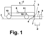
- a vehicle 1 travels on a roadway 2.
- the direction of travel of the vehicle 1 is in the usual way as X, the vertical direction as Z and the out Fig. 2, 3rd apparent transverse direction referred to as Y, which together form a vehicle coordinate system.
- the X direction and the Y direction define the horizontal plane.
- a sensor holder 5 On the vehicle 1, z. B. on its bumper 3 and a mounted on the bumper 3 mounting plate 4, a sensor holder 5 according to the invention with a in Fig. 2, 3rd Dashed line distance sensor 6 attached.
- the sensor holder 5 with the distance sensor 6 received by it form an inventive sensor system 7.
- An attachment of the sensor system 7 is not only on the bumper 3 and the rear of the vehicle 1, but in principle also z. B. on the sides for detecting a lateral distance, or even on the front side of the vehicle 1 possible. In this case, another height can be selected on the vehicle 1.
- the distance sensor 6 outputs a sensor signal S1, which can be recorded in the vehicle 1 by a control device 8 to evaluate a distance d to an obstacle 9 and z. B. output a warning signal falls below a minimum distance, and optionally also to control braking devices 10 of the vehicle, if the distance sensor 6 is part of a self-contained vehicle brake control system or vehicle vehicle dynamics control system. In principle, however, the sensor signals S1 can also be evaluated within the sensor holder 5, which then z. B. outputs a warning signal falls below the minimum distance.
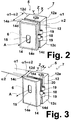
- the sensor holder 5 is constructed in several parts according to the invention; According to the embodiment shown, it has two parts, namely as a fixing part, a housing 12 which is fixed to the chassis-side mounting plate 4, for. B. with its flat rear side 12 a, and a receiving part, which is designed here as a lid 14.
- the distance sensor 6 may, for. B. be formed substantially cuboid and is attached to the lid 14. In this case, the distance sensor 6 is received in the housing 12 and covered to the rear by the lid 14. In the lid 14, an opening 15 is formed, through which the sensitive surface of the distance sensor 6 detects a detection area around the sensor axis A.
- the housing 12 is formed with a relation to the vertical YZ plane oblique or inclined first positioning surface 12 b, the z. B. by the four leading edges of the housing 12, that is, the edge surfaces of its two side walls and the edge surfaces of the upper wall and the lower wall is formed. Accordingly, on the lid 14, a second Positioning surface 14 a formed, for. B. also by the edge surfaces of its horizontal top and bottom wall and its side walls 14c and 14d. Also, the second positioning surface 14a is offset from the vertical YZ plane.
- the positioning surfaces 14a and 12b are adjacent to each other, for. B. with a seal between them.
- the first positioning surface 12b is inclined to the vertical YZ plane by a first inclination angle ⁇ 1, which is thus in the horizontal XY plane.
- ⁇ 1 a first inclination angle
- z. B. the right side wall 12c of the housing 12 may be slightly longer than its left side wall 12d.
- the second positioning surface 14a is inclined relative to the vertical YZ plane by a second inclination angle ⁇ 2, which thus also lies in the horizontal XY plane, to which the side walls 14c and 14d of the lid 14 may be different in length.
- a vertically continuous bearing eye (attachment eyelet) 18 is provided centrally. Accordingly, two bearing lugs 19 are respectively provided on the side walls 12c and 12d of the housing 12, which are aligned with the attachment of the lid 14 on the housing 12 with the bearing eye 18, so that on both sides in each case FIG. 3 schematically drawn fastening bolt 20 can be set by the bearing eyes 18, 19 to lock the lid 14 on both sides with the housing 12 and lock.
- the lid 14 may be attached to the housing 12 in two positions with its bearing lugs 18 respectively received between the respective bearing lugs 19 of the housing 12.
- the lid 14 In the second position of the Fig. 3 the lid 14 is opposite Fig. 2 rotated by 180 ° with respect to the X direction, ie its side surfaces 14c and 14d are reversed left and right, as well as by the offset Position of the hole 15 can be seen.
- the positioning surfaces 12b and 14a are adjacent to each other.
- the distance sensor 6 Since the distance sensor 6 is attached to the lid 14, it is rotated with.
- the sensor axis A thus runs in FIGS. 2 and 3 different in the XY plane.
- a sensor system 7 can be mounted, wherein the sensor holder 5 in accordance with Fig. 3 is twisted outwards in the horizontal XY plane.
- This in Fig. 3 shown sensor system can be mounted left as shown.
- For mounting on the right side it can be opposite Fig. 3 be rotated 180 ° in total, so that the sensor axis A points to the right outside.
- the distance sensor 6 may, for. B. be an ultrasonic sensor or radar sensor. According to its design, the hole 15 may optionally be closed (in the case of training as a radar sensor) with a transparent cover.
Description
Die Erfindung betrifft eine Sensorhalterung für einen Entfernungssensor, ein Sensor-System mit der Sensorhalterung und einem Entfernungssensor sowie ein Fahrzeug mit einem derartigen Sensor-System.The invention relates to a sensor holder for a distance sensor, a sensor system with the sensor holder and a distance sensor and a vehicle with such a sensor system.
Zur Detektion von Entfernungen bzw. Abständen können an einem Fahrzeug unterschiedliche Entfernungssensoren befestigt werden. So sind z. B. Ultraschall- und Radar-Entfernungssensoren bekannt, die innerhalb eines Raumwinkels den Abstand bzw. die Entfernung zu weiteren Objekten detektieren können.To detect distances or distances different distance sensors can be attached to a vehicle. So z. As ultrasonic and radar range sensors are known, which can detect the distance or the distance to other objects within a solid angle.
Für z. B. Rückraumüberwachungssysteme und Rampenanfahrsysteme werden derartige Entfernungssensoren am Fahrzeugheck angebracht. Je nach Aufgabe werden die Sensoren in verschiedenen Winkeln zur Längsachse angeordnet, um den erforderlichen Überwachungsbereich mit möglichst wenigen Sensoren abdecken zu können.For z. B. rear space monitoring systems and Rampanfahrsysteme such distance sensors are mounted on the rear of the vehicle. Depending on the task, the sensors are arranged at different angles to the longitudinal axis in order to cover the required monitoring area with as few sensors as possible.
Die Entfernungssensoren werden im Allgemeinen durch Sensorhalterungen am Fahrzeug, z. B. an dem Fahrzeugchassis oder der Stoßstange befestigt. Somit sind im Allgemeinen mehrere Sensorhalterungen für die verschiedenen Winkelstellungen der Sensoren erforderlich, z. B. seitliche Sensorhalterungen und ein mittiger Sensorhalter.The distance sensors are generally supported by sensor mounts on the vehicle, e.g. B. attached to the vehicle chassis or the bumper. Thus, in general, multiple sensor mounts are required for the various angular positions of the sensors, e.g. B. lateral sensor mounts and a central sensor holder.
Hierdurch erhöhen sich entsprechend die Teilevielfalt bei Fahrzeugherstellern sowie die Kosten für die Werkzeuge zur Herstellung der Sensorhalterungen, wobei die verschiedenen Sensorhalterungen separat zu testen und freizugeben sind.This increases accordingly the variety of parts in vehicle manufacturers and the cost of the tools for the production of the sensor mounts, the different sensor mounts are tested separately and released.
Der Erfindung liegt die Aufgabe zugrunde, eine Sensorhalterung zu schaffen, die am oder im Fahrzeug flexibel bzw. einstellbar anbringbar ist.The invention has for its object to provide a sensor holder which is flexible or adjustable attachable on or in the vehicle.
Diese Aufgabe wird durch eine Sensorhalterung nach Anspruch 1, ein Sensor-System nach Anspruch 11 sowie ein Fahrzeug mit einem derartigen Sensor-System nach Anspruch 12 gelöst. Die Unteransprüche beschreiben bevorzugte Weiterbildungen.This object is achieved by a sensor holder according to
Erfindungsgemäß ist die Sensorhalterung somit im wesentlichen zweiteilig ausgebildet, mit einem Befestigungsteil zur Befestigung am Fahrzeug, z. B. dem Fahrzeugchassis oder der Stoßstange, und einem den Entfernungssensor aufnehmenden Aufnahmeteil. Das Befestigungsteil kann hierbei ein Gehäuse sein, das den Entfernungssensor umgibt, und das Aufnahmeteil ein das Gehäuse verschließender Deckel, an dem der Entfernungssensor fixiert ist. Somit kann der Deckel mit fixiertem Entfernungssensor in der gewünschten Winkelstellung auf das Gehäuse gesetzt und befestigt werden.According to the invention, the sensor holder is thus formed substantially in two parts, with a fastening part for attachment to the vehicle, for. B. the vehicle chassis or bumper, and a receiving the receiving sensor receiving the distance. The fastening part may in this case be a housing which surrounds the distance sensor, and the receiving part a cover closing the housing, on which the distance sensor is fixed. Thus, the cover with fixed distance sensor can be set and fixed in the desired angular position on the housing.
Das Befestigungsteil kann hierbei direkt und oder indirekt am Fahrzeug befestigt werden, z. B. an einer Montageplatte. Das Aufnahmeteil ist erfindungsgemäß in mindestens zwei Winkelstellungen an dem Befestigungsteil befestigbar, wobei die Winkelstellung des Aufnahmeteils die Winkelstellungen des Entfernungssensors definiert.The fastening part can in this case be attached directly and or indirectly to the vehicle, for. B. on a mounting plate. The receiving part is inventively fastened in at least two angular positions on the fastening part, wherein the angular position of the receiving part defines the angular positions of the distance sensor.
Somit ist der Entfernungssensor in den unterschiedlichen Winkelstellungen des Aufnahmeteils mit einer unterschiedlichen Ausrichtung seiner Sensorachse aufgenommen. Der Benutzer kann somit durch die Winkelstellung des Aufnahmeteils die Ausrichtung der Sensorachse einstellen.Thus, the distance sensor is received in the different angular positions of the receiving part with a different orientation of its sensor axis. The user can thus adjust the orientation of the sensor axis by the angular position of the receiving part.
Die unterschiedlichen Winkelstellungen der Sensorachse können insbesondere in der horizontalen Ebene, d.h. der XY-Ebene des Fahrzeugs liegen.The different angular positions of the sensor axis can, in particular in the horizontal plane, i. the XY plane of the vehicle.
Gemäß einer bevorzugten Ausbildung kann das Aufnahmeteil an dem Befestigungsteil in genau zwei Winkelstellungen angebracht werden, die zueinander um 180° verdreht sind, wodurch zwei unterschiedliche Ausrichtungen der Sensorachse in der horizontalen Ebene festgelegt werden.According to a preferred embodiment, the receiving part can be attached to the fastening part in exactly two angular positions, which are rotated by 180 ° to each other, whereby two different orientations of the sensor axis are determined in the horizontal plane.
Eine erste Winkelstellung kann hierbei derartig verlaufen, dass die Sensorachse im Wesentlichen in Fahrzeuglängsrichtung (bzw. entgegengesetzt der Fahrzeug-x-Richtung) verläuft.A first angular position can in this case run in such a way that the sensor axis runs essentially in the vehicle longitudinal direction (or opposite to the vehicle x-direction).
In dieser Winkelstellung kann die Sensorhalterung z. B. mittig am Fahrzeugheck montiert werden und einen Abstand nach hinten detektieren. In der weiteren Winkelstellung liegt eine Ausrichtung der Sensorachse in der horizontalen Ebene zur Seite hin vor. Je nach Montage der gesamten Sensorhalterung kann diese Ausrichtung nach links oder rechts weisen, so dass insgesamt drei Sensor-Systeme mit Ausrichtungen zur Mitte sowie nach links und rechts angebracht werden können.In this angular position, the sensor holder z. B. be mounted centrally on the rear of the vehicle and detect a distance to the rear. In the further angular position is an alignment of the sensor axis in the horizontal plane to the side before. Depending on how the entire sensor mount is mounted, this orientation can be left or right, allowing a total of three sensor systems with center, left, and right alignments.
Erfindungsgemäß ergeben sich einige Vorteile. So werden die Herstellungskosten deutlich gesenkt, da für die verschiedenen Sensorausrichtungen eine einheitliche Sensorhalterung eingesetzt werden kann.According to the invention, there are some advantages. Thus, the production costs are significantly reduced, since a uniform sensor holder can be used for the different sensor orientations.
Die Verstellung kann durch den Benutzer selbst vorgenommen werden. Hierzu kann z. B. eine formschlüssige Arretierung des Befestigungsteils am Aufnahmeteil erfolgen, z. B. mittels Lageraugen bzw. Befestigungsösen, die an den beiden Teilen ausgebildet und durch Befestigungsbolzen miteinander verbunden bzw. fixiert werden. Somit sind eindeutige Positionen für den Benutzer mit relativ wenig Aufwand einstellbar.The adjustment can be made by the user himself. For this purpose, z. B. a positive locking of the fastening part on the receiving part, z. B. by means of bearing eyes or eyelets, which are formed on the two parts and connected or fixed together by fastening bolts. Thus, unique positions are adjustable for the user with relatively little effort.
Die erfindungsgemäße Sensorhalterung zeichnet sich weiterhin auch durch eine geringe Teileanzahl und Robustheit aus. Grundsätzlich sind nur das Befestigungsteil und das Aufnahmeteil erforderlich, gegebenenfalls mit Arretierungsmitteln wie Befestigungsbolzen oder auch gegebenenfalls einer Dichtung zwischen ihren zur gegenseitigen Anlage dienenden Positionierungsflächen.The sensor holder according to the invention is further characterized by a low number of parts and robustness. Basically, only the fastening part and the receiving part are required, optionally with locking means such as fastening bolts or optionally also a seal between their positioning surfaces serving for mutual contact.
Die Erfindung wird im Folgenden anhand der beiliegenden Zeichnungen an einer Ausführungsform erläutert. Es zeigen:
- Fig. 1
- ein Fahrzeug mit einem erfindungsgemäßen Sensor-System;
- Fig. 2
- die erfindungsgemäße Sensorhalterung in ihrer ersten Winkelstellung;
- Fig. 3
- die Sensorhalterung aus
Fig. 2 in ihrer zweiten Winkelstellung.
- Fig. 1
- a vehicle with a sensor system according to the invention;
- Fig. 2
- the sensor holder according to the invention in its first angular position;
- Fig. 3
- the sensor holder off
Fig. 2 in its second angular position.
Ein Fahrzeug 1 fährt auf einer Fahrbahn 2. Die Fahrtrichtung des Fahrzeugs 1 wird in üblicher Weise als X, die hierzu vertikale Richtung als Z und die aus
An dem Fahrzeug 1, z. B. an seiner Stoßstange 3 bzw. einer an der Stoßstange 3 befestigten Montageplatte 4, ist eine erfindungsgemäße Sensorhalterung 5 mit einem in
Der Entfernungssensor 6 gibt ein Sensorsignal S1 aus, das im Fahrzeug 1 von einer Steuereinrichtung 8 aufgenommen werden kann, um einen Abstand d zu einem Hindernis 9 auszuwerten und z. B. ein Warnsignal bei Unterschreiten eines Mindestabstands auszugeben, sowie gegebenenfalls auch Bremseinrichtungen 10 des Fahrzeugs anzusteuern, falls der Entfernungssensor 6 Teil eines selbständigen Fahrzeug-Bremsregelsystems bzw. Fahrzeug-Fahrdynamikregelsystems ist. Grundsätzlich können die Sensorsignale S1 aber auch bereits innerhalb der Sensorhalterung 5 ausgewertet werden, die dann z. B. ein Warnsignal bei Unterschreiten des Mindestabstands ausgibt.The
Die Sensorhalterung 5 ist erfindungsgemäß mehrteilig aufgebaut; gemäß der gezeigten Ausführungsform weist sie zwei Teile auf, nämlich als Befestigungsteil ein Gehäuse 12, das an der chassisseitigen Montageplatte 4 befestigt wird, z. B. mit seiner planen Rückseite 12a, sowie ein Aufnahmeteil, das hier als Deckel 14 ausgebildet ist. Der Entfernungssensor 6 kann z. B. im Wesentlichen quaderförmig ausgebildet sein und ist an dem Deckel 14 befestigt. Hierbei wird der Entfernungssensor 6 in dem Gehäuse 12 aufgenommen und nach hinten durch den Deckel 14 abgedeckt. Im Deckel 14 ist eine Öffnung 15 ausgebildet, durch den die sensitive Fläche des Entfernungssensors 6 einen Erfassungsbereich um die Sensorachse A detektiert.The
Das Gehäuse 12 ist mit einer gegenüber der vertikalen YZ-Ebene schrägen bzw. geneigten ersten Positionierungsfläche 12b ausgebildet, die z. B. durch die vier Vorderkanten des Gehäuses 12, d.h. die Kantenflächen seiner beiden Seitenwände und die Kantenflächen der oberen Wand und der unteren Wand gebildet ist. Entsprechend ist an dem Deckel 14 eine zweite Positionierungsfläche 14a ausgebildet, z. B. ebenfalls durch die Kantenflächen seiner horizontalen Ober- und Unterwand sowie seiner Seitenwände 14c und 14d. Auch die zweite Positionierungsfläche 14a ist gegenüber der vertikalen YZ-Ebene versetzt. Die Positionierungsflächen 14a und 12b liegen aneinander, z. B. mit einer Dichtung zwischen ihnen.The
Gemäß
Entsprechend ist die zweite Positionierungsfläche 14a gegenüber der vertikalen YZ-Ebene um einen zweiten Neigungswinkel α2 geneigt, der somit auch in der horizontalen XY-Ebene liegt, wozu die Seitenwände 14c und 14d des Deckels 14 unterschiedlich lang sein können.Accordingly, the
An beiden Seitenwänden 14c und 14d des Deckels 14 ist jeweils ein vertikal durchgängiges Lagerauge (Befestigungsöse) 18 mittig vorgesehen. Entsprechend sind an den Seitenwänden 12c und 12d des Gehäuses 12 jeweils zwei Lageraugen 19 vorgesehen, die bei Anbringung des Deckels 14 am Gehäuse 12 mit dem Lagerauge 18 fluchten, damit an beiden Seiten jeweils ein in
Gemäß
Da der Entfernungssensor 6 am Deckel 14 befestigt ist, wird er mit verdreht. Die Sensorachse A verläuft somit in
Indem die Neigungswinkel α1 = α2 gewählt werden, verläuft in
Grundsätzlich sind auch komplexere Winkelverstellungen als durch die gezeigte einfache Anlage von Positionierungsflächen 12b und 14a möglich. So sind z. B. quadratische Ausbildungen der Sensorhalterung mit 4-zähliger (statt 2-zähliger) Symmetrie möglich.In principle, more complex angle adjustments are possible than by the simple installation of positioning surfaces 12b and 14a shown. So z. B. square configurations of the sensor holder with 4-fold (instead of 2-fold) symmetry possible.
Erfindungsgemäß können an der Stoßstange 3 z. B. drei Sensor-Systeme 7 montiert werden: in der Mitte der Stoßstange 3 kann z. B. das Sensor-System 7 nach
Der Entfernungssensor 6 kann z. B. ein Ultraschallsensor oder Radarsensor sein. Entsprechend seiner Ausbildung kann das Loch 15 gegebenenfalls (bei Ausbildung als Radarsensor) mit einer transparenten Abdeckung verschlossen sein.The
Claims (13)
- Sensor mounting (5) for a distance sensor (6), wherein the sensor mounting (5) at least comprises:an attachment part (12) for attachment to a vehicle (1),an accommodating part (14) adjustably attached to the attachment part (12) for accommodating the distance sensor (6),wherein the accommodating part (14) can be adjusted on the attachment part (12) in at least two different angular positions, characterized in that- the attachment part is a housing (12) and- the accommodating part is a cover (14) that closes the housing (12),wherein the distance sensor (6) is attached to the cover (14) and enclosed by the housing (12),wherein the cover is rotated through 180° in each of the two angular positions relative to the other position.
- Sensor mounting (5) according to Claim 1, characterized in that a sensor axis (A) of the distance sensor (6) accommodated by the accommodating part (14) extends in different directions in the two angular positions of the accommodating part (14).
- Sensor mounting (5) according to Claim 2, characterized in that the sensor axis (A) lies in a horizontal plane (XY) of the vehicle (1) in each of the different angular positions.
- Sensor mounting (5) according to Claim 2 or 3, characterized in that the sensor axis (A) extends in a first angular position essentially parallel to the vehicle's longitudinal direction (X) and in a second angular position (α1+ α2) is offset relative to the vehicle's longitudinal direction (X).
- Sensor mounting (5) according to any one of the preceding claims, characterized in that the attachment part (12) comprises a first positioning surface (12b) and the accommodating part (14) comprises a second positioning surface (14a), which are in direct contact respectively with each other in the different angular positions.
- Sensor mounting (5) according to any one of the Claims 1 to 4 and according to Claim 5, characterized in that
the first positioning surface (12b) has a first inclination angle (α1) relative to a vertical plane (YZ) and the second positioning surface (14a) has a second inclination angle (α2) relative to the vertical plane (YZ),
the first and second inclination angles (α1, α2) are of approximately equal magnitude, so that the sensor axis (A) of the distance sensor (6) in the second angular position is displaced by approximately double the inclination angle (α1 + α2) relative to the first angular position. - Sensor mounting (5) according to any one of the preceding claims, characterized in that the accommodating part (14) can be positively latched to the attachment part (12) in the at least two angular positions.
- Sensor mounting (5) according to Claim 7, characterized in that the accommodating part (14) and the attachment part (12) each comprise bearing eyes (18, 19) or fixing eyelets, which can be positively locked by fixing bolts (20) in the respective angular positions.
- Sensor mounting (5) according to any one of the preceding claims, characterized in that an opening (15) is formed in the accommodating part (14) for the distance sensor (6) for detecting the exterior through the opening (15).
- Sensor mounting (5) according to any one of the preceding claims, characterized in that it is essentially of rectangular form and the attachment part (12) and the accommodating part (14) each form parts of the rectangular shape, wherein lateral surfaces (12a, 12c, 12d; 14e, 14c, 14d) of the attachment part (12) and the accommodating part (14) are essentially formed parallel to each other or merge together in at least one angular position.
- Sensor system (7), which comprises at least:a sensor mounting (5) according to any one of the preceding claims, and a distance sensor (6) accommodated by or in the sensor mounting (5) for the detection of a distance (d) to an object (9).
- Vehicle (1), which comprises at least one sensor system (7) according to Claim 11 and a controller (8) for receiving the sensor signals (S1) of the at least one sensor system (7),
wherein the sensor system (7) is attached to the rear of the vehicle (1) and is essentially orientated towards the rear,
wherein the sensor system (7) in a first angular position is essentially orientated with its sensor axis (A) towards the rear opposite to the vehicle's longitudinal direction (X) and in at least another angular position is essentially orientated laterally rearwards. - Vehicle (1) according to Claim 12, characterized in that it comprises at least three sensor systems (7),
wherein a central sensor system (7) is set in the first angular position and a left and a right sensor system (7) are each set in the second angular position,
wherein the central sensor system (7) is orientated with its sensor axis (A) towards the rear essentially opposite and parallel to the vehicle's longitudinal direction (X),
the left sensor system (7) is orientated with its sensor axis (A) in the horizontal plane (xy) outwards to the left,
the right sensor system (7) is orientated with its sensor axis (A) in the horizontal plane (xy) outwards to the right,
wherein the housings (12) of the left sensor system (7) and the right sensor system (7) are attached to mounting devices (4) of the vehicle (1) in positions that are rotated by 180° relative to each other.
Priority Applications (1)
| Application Number | Priority Date | Filing Date | Title |
|---|---|---|---|
| PL11745690T PL2622367T3 (en) | 2010-10-02 | 2011-07-21 | Sensor mounting for a distance sensor |
Applications Claiming Priority (2)
| Application Number | Priority Date | Filing Date | Title |
|---|---|---|---|
| DE102010047403A DE102010047403A1 (en) | 2010-10-02 | 2010-10-02 | Sensor holder for a distance sensor |
| PCT/EP2011/003657 WO2012041414A1 (en) | 2010-10-02 | 2011-07-21 | Sensor mounting for a distance sensor |
Publications (2)
| Publication Number | Publication Date |
|---|---|
| EP2622367A1 EP2622367A1 (en) | 2013-08-07 |
| EP2622367B1 true EP2622367B1 (en) | 2016-09-07 |
Family
ID=44514613
Family Applications (1)
| Application Number | Title | Priority Date | Filing Date |
|---|---|---|---|
| EP11745690.5A Active EP2622367B1 (en) | 2010-10-02 | 2011-07-21 | Sensor mounting for a distance sensor |
Country Status (7)
| Country | Link |
|---|---|
| US (1) | US9194725B2 (en) |
| EP (1) | EP2622367B1 (en) |
| CN (2) | CN103038665A (en) |
| DE (1) | DE102010047403A1 (en) |
| ES (1) | ES2604487T3 (en) |
| PL (1) | PL2622367T3 (en) |
| WO (1) | WO2012041414A1 (en) |
Families Citing this family (11)
| Publication number | Priority date | Publication date | Assignee | Title |
|---|---|---|---|---|
| CN103847649B (en) * | 2012-12-03 | 2016-02-10 | 北汽福田汽车股份有限公司 | Automobile test instrument fixing device |
| US9193321B2 (en) * | 2013-06-21 | 2015-11-24 | Continental Automotive Systems, Inc. | Multi-axis vehicle sensor mounting |
| CN106274716B (en) * | 2015-05-29 | 2018-08-31 | 财团法人车辆研究测试中心 | The detecting angle vernier device of radar sensor |
| CN105059229B (en) * | 2015-09-07 | 2017-10-27 | 清华大学苏州汽车研究院(吴江) | Improved vehicle-mounted ultrasonic wave sensor fixing device |
| US9849842B1 (en) * | 2016-08-11 | 2017-12-26 | GM Global Technology Operations LLC | Resettable tranceiver bracket |
| USD818932S1 (en) * | 2016-10-12 | 2018-05-29 | Marcellus Lee Reid | Reinforced covers for storage compartments |
| JP6659743B2 (en) * | 2018-01-18 | 2020-03-04 | 本田技研工業株式会社 | External sensor unit of vehicle |
| USD949086S1 (en) | 2018-05-24 | 2022-04-19 | Stephen Christopher Swift | Reinforced cover for storage compartments |
| DE102018121271A1 (en) * | 2018-08-31 | 2020-03-05 | Wabco Europe Bvba | Vehicle operating device and method for changing the display angle of an operating and display device of such a vehicle operating device |
| CN109506693A (en) * | 2018-09-26 | 2019-03-22 | 初速度(苏州)科技有限公司 | A kind of acquisition of autonomous driving vehicle data concealed bracket and its acquisition method |
| US11383728B2 (en) | 2019-03-14 | 2022-07-12 | Cnh Industrial America Llc | System and method for collecting data associated with the operation of an agricultural machine in different operating modes |
Family Cites Families (16)
| Publication number | Priority date | Publication date | Assignee | Title |
|---|---|---|---|---|
| US3898652A (en) * | 1973-12-26 | 1975-08-05 | Rashid Mary D | Vehicle safety and protection system |
| SE435652B (en) | 1982-12-29 | 1984-10-08 | Ericsson Telefon Ab L M | DEVICE FOR ADJUSTING THE PLAN OF A DEVICE PLATFORM IN AN ELECTIBLE SLEEP |
| DE4333066A1 (en) * | 1993-09-29 | 1995-03-30 | Bosch Gmbh Robert | Device for mounting a sleeve-shaped body on a vehicle part |
| DE4439797A1 (en) | 1994-11-08 | 1996-05-09 | Moto Meter Gmbh | Fastening element for a body in a wall |
| GB9612373D0 (en) * | 1996-06-13 | 1996-08-14 | Autosonics Ltd | Sensor mounting |
| US5860327A (en) * | 1997-06-10 | 1999-01-19 | Stanev; Stefan | Apparatus for two dimensional orientation of an object |
| EP1005692B2 (en) | 1997-08-21 | 2006-12-27 | Valeo Schalter und Sensoren GmbH | Sleeve for receiving a sensor, connected to the bumper of an automobile |
| DE19758075C2 (en) * | 1997-08-21 | 2003-05-08 | Itt Mfg Enterprises Inc | Receiving sleeve for sensors connected to the bumper of a motor vehicle |
| JPH11108948A (en) * | 1997-10-06 | 1999-04-23 | Toyota Autom Loom Works Ltd | Structure for mounting sensor in vehicle |
| US6268803B1 (en) * | 1998-08-06 | 2001-07-31 | Altra Technologies Incorporated | System and method of avoiding collisions |
| DE10026454C1 (en) | 2000-05-27 | 2001-12-20 | Daimler Chrysler Ag | Radome for a distance warning radar (AWR) |
| DE10316535B3 (en) * | 2003-04-10 | 2005-01-05 | Rehau Ag + Co. | Installation unit for automobile radar sensors has adapter receiving radar sensor housing with separate spaces for radar transmission and radar reception components |
| US6809806B1 (en) * | 2003-05-27 | 2004-10-26 | International Truck Intellectual Property Company, Llc | Apparatus and method for verifying the beam axis of front-looking land vehicle transceiver antenna |
| US7546780B2 (en) * | 2005-09-30 | 2009-06-16 | Rockwell Automation Technologies, Inc. | Sensor mounting structure allowing for adjustment of sensor position |
| DE102006056391B3 (en) * | 2006-11-29 | 2008-04-30 | Siemens Ag | Navigation computer for motor vehicle, has gyro sensor for determining turning of vehicle around vertical axis, and base plate fastened in set of fastening planes of holder, and extends in different inclination angles to mounting plane |
| US20090256698A1 (en) * | 2008-04-10 | 2009-10-15 | Estevan Bonilla | Brake light warning system with early warning feature |
-
2010
- 2010-10-02 DE DE102010047403A patent/DE102010047403A1/en not_active Withdrawn
-
2011
- 2011-07-21 WO PCT/EP2011/003657 patent/WO2012041414A1/en active Application Filing
- 2011-07-21 CN CN2011800373016A patent/CN103038665A/en active Pending
- 2011-07-21 EP EP11745690.5A patent/EP2622367B1/en active Active
- 2011-07-21 ES ES11745690.5T patent/ES2604487T3/en active Active
- 2011-07-21 US US13/825,849 patent/US9194725B2/en active Active
- 2011-07-21 CN CN201710153329.5A patent/CN107085200A/en active Pending
- 2011-07-21 PL PL11745690T patent/PL2622367T3/en unknown
Also Published As
| Publication number | Publication date |
|---|---|
| US9194725B2 (en) | 2015-11-24 |
| US20130186211A1 (en) | 2013-07-25 |
| DE102010047403A1 (en) | 2012-04-05 |
| EP2622367A1 (en) | 2013-08-07 |
| WO2012041414A1 (en) | 2012-04-05 |
| PL2622367T3 (en) | 2017-08-31 |
| CN107085200A (en) | 2017-08-22 |
| CN103038665A (en) | 2013-04-10 |
| ES2604487T3 (en) | 2017-03-07 |
Similar Documents
| Publication | Publication Date | Title |
|---|---|---|
| EP2622367B1 (en) | Sensor mounting for a distance sensor | |
| DE102017205872B4 (en) | Mounting structure for peripheral information detection sensor | |
| DE102014205929B4 (en) | radar mount | |
| EP2422214B1 (en) | Sensor assembly for driver assistance systems in motor vehicles | |
| EP2567837B1 (en) | Carrier unit | |
| DE102016123752A1 (en) | SENSOR DEVICE | |
| DE102015103542A1 (en) | System and method for determining and compensating for misalignment of a sensor | |
| EP3510463A1 (en) | Sensor array for an autonomously operated utility vehicle and method for surround-view image acquisition | |
| DE102018106855A1 (en) | Measuring device for measuring forces and / or moments between a motorized vehicle and a trailer or attachment pulled or pushed by it | |
| EP3553483A2 (en) | Measuring device for measuring force and / or moments between a motorized vehicle and a pulled or pushed trailer | |
| DE102009009046A1 (en) | Measuring device for aligning sensor unit of driver assistance system of vehicle, comprises detection units, which receive signal from sensor unit, and center point of measuring device is arranged on geometrical driving axis of vehicle | |
| DE102015203882B4 (en) | Wheel mounting unit for car sensor calibration and calibration device using the same | |
| DE112019002066T5 (en) | A radar device for a vehicle and a method for detecting misalignment | |
| EP3152070A1 (en) | Trailer coupling | |
| EP2768701B1 (en) | Optical device for a vehicle | |
| DE60012122T2 (en) | System for determining the orientation of a directional radar antenna | |
| EP3295779B1 (en) | Upper guide for a three point power lift of an agricultural tractor | |
| DE102018212251B4 (en) | Method for tracking the adjustment of a radar sensor in a motor vehicle and motor vehicle | |
| DE202021101591U1 (en) | Detection device for detecting the presence of a person on the side of a commercial vehicle | |
| DE102018218537A1 (en) | Sensor arrangement and motor vehicle | |
| DE102014018472A1 (en) | Weighing device and weighing system for vehicle trailers | |
| EP4028313B1 (en) | Coupling system | |
| DE102017003759A1 (en) | Adjustment device and method for adjusting a sensor for object detection on a vehicle | |
| DE102020113188B3 (en) | Motor vehicle with a vehicle roof | |
| WO2009129877A1 (en) | Method and device for detecting a position and/or an orientation of a camera |
Legal Events
| Date | Code | Title | Description |
|---|---|---|---|
| PUAI | Public reference made under article 153(3) epc to a published international application that has entered the european phase |
Free format text: ORIGINAL CODE: 0009012 |
|
| 17P | Request for examination filed |
Effective date: 20130502 |
|
| AK | Designated contracting states |
Kind code of ref document: A1 Designated state(s): AL AT BE BG CH CY CZ DE DK EE ES FI FR GB GR HR HU IE IS IT LI LT LU LV MC MK MT NL NO PL PT RO RS SE SI SK SM TR |
|
| DAX | Request for extension of the european patent (deleted) | ||
| REG | Reference to a national code |
Ref country code: DE Ref legal event code: R079 Ref document number: 502011010643 Country of ref document: DE Free format text: PREVIOUS MAIN CLASS: G01S0013930000 Ipc: G01S0015930000 |
|
| GRAP | Despatch of communication of intention to grant a patent |
Free format text: ORIGINAL CODE: EPIDOSNIGR1 |
|
| RIC1 | Information provided on ipc code assigned before grant |
Ipc: G01D 11/30 20060101ALI20160401BHEP Ipc: G01S 15/93 20060101AFI20160401BHEP Ipc: G01S 13/93 20060101ALI20160401BHEP |
|
| INTG | Intention to grant announced |
Effective date: 20160428 |
|
| GRAS | Grant fee paid |
Free format text: ORIGINAL CODE: EPIDOSNIGR3 |
|
| GRAA | (expected) grant |
Free format text: ORIGINAL CODE: 0009210 |
|
| AK | Designated contracting states |
Kind code of ref document: B1 Designated state(s): AL AT BE BG CH CY CZ DE DK EE ES FI FR GB GR HR HU IE IS IT LI LT LU LV MC MK MT NL NO PL PT RO RS SE SI SK SM TR |
|
| REG | Reference to a national code |
Ref country code: GB Ref legal event code: FG4D Free format text: NOT ENGLISH |
|
| REG | Reference to a national code |
Ref country code: CH Ref legal event code: EP |
|
| REG | Reference to a national code |
Ref country code: IE Ref legal event code: FG4D Free format text: LANGUAGE OF EP DOCUMENT: GERMAN |
|
| REG | Reference to a national code |
Ref country code: AT Ref legal event code: REF Ref document number: 827341 Country of ref document: AT Kind code of ref document: T Effective date: 20161015 |
|
| REG | Reference to a national code |
Ref country code: DE Ref legal event code: R096 Ref document number: 502011010643 Country of ref document: DE |
|
| REG | Reference to a national code |
Ref country code: NL Ref legal event code: FP |
|
| REG | Reference to a national code |
Ref country code: SE Ref legal event code: TRGR |
|
| REG | Reference to a national code |
Ref country code: LT Ref legal event code: MG4D |
|
| PG25 | Lapsed in a contracting state [announced via postgrant information from national office to epo] |
Ref country code: RS Free format text: LAPSE BECAUSE OF FAILURE TO SUBMIT A TRANSLATION OF THE DESCRIPTION OR TO PAY THE FEE WITHIN THE PRESCRIBED TIME-LIMIT Effective date: 20160907 Ref country code: HR Free format text: LAPSE BECAUSE OF FAILURE TO SUBMIT A TRANSLATION OF THE DESCRIPTION OR TO PAY THE FEE WITHIN THE PRESCRIBED TIME-LIMIT Effective date: 20160907 Ref country code: NO Free format text: LAPSE BECAUSE OF FAILURE TO SUBMIT A TRANSLATION OF THE DESCRIPTION OR TO PAY THE FEE WITHIN THE PRESCRIBED TIME-LIMIT Effective date: 20161207 Ref country code: LT Free format text: LAPSE BECAUSE OF FAILURE TO SUBMIT A TRANSLATION OF THE DESCRIPTION OR TO PAY THE FEE WITHIN THE PRESCRIBED TIME-LIMIT Effective date: 20160907 Ref country code: FI Free format text: LAPSE BECAUSE OF FAILURE TO SUBMIT A TRANSLATION OF THE DESCRIPTION OR TO PAY THE FEE WITHIN THE PRESCRIBED TIME-LIMIT Effective date: 20160907 |
|
| PG25 | Lapsed in a contracting state [announced via postgrant information from national office to epo] |
Ref country code: LV Free format text: LAPSE BECAUSE OF FAILURE TO SUBMIT A TRANSLATION OF THE DESCRIPTION OR TO PAY THE FEE WITHIN THE PRESCRIBED TIME-LIMIT Effective date: 20160907 Ref country code: GR Free format text: LAPSE BECAUSE OF FAILURE TO SUBMIT A TRANSLATION OF THE DESCRIPTION OR TO PAY THE FEE WITHIN THE PRESCRIBED TIME-LIMIT Effective date: 20161208 |
|
| REG | Reference to a national code |
Ref country code: ES Ref legal event code: FG2A Ref document number: 2604487 Country of ref document: ES Kind code of ref document: T3 Effective date: 20170307 |
|
| PG25 | Lapsed in a contracting state [announced via postgrant information from national office to epo] |
Ref country code: EE Free format text: LAPSE BECAUSE OF FAILURE TO SUBMIT A TRANSLATION OF THE DESCRIPTION OR TO PAY THE FEE WITHIN THE PRESCRIBED TIME-LIMIT Effective date: 20160907 Ref country code: RO Free format text: LAPSE BECAUSE OF FAILURE TO SUBMIT A TRANSLATION OF THE DESCRIPTION OR TO PAY THE FEE WITHIN THE PRESCRIBED TIME-LIMIT Effective date: 20160907 |
|
| PG25 | Lapsed in a contracting state [announced via postgrant information from national office to epo] |
Ref country code: PT Free format text: LAPSE BECAUSE OF FAILURE TO SUBMIT A TRANSLATION OF THE DESCRIPTION OR TO PAY THE FEE WITHIN THE PRESCRIBED TIME-LIMIT Effective date: 20170109 Ref country code: CZ Free format text: LAPSE BECAUSE OF FAILURE TO SUBMIT A TRANSLATION OF THE DESCRIPTION OR TO PAY THE FEE WITHIN THE PRESCRIBED TIME-LIMIT Effective date: 20160907 Ref country code: BG Free format text: LAPSE BECAUSE OF FAILURE TO SUBMIT A TRANSLATION OF THE DESCRIPTION OR TO PAY THE FEE WITHIN THE PRESCRIBED TIME-LIMIT Effective date: 20161207 Ref country code: SM Free format text: LAPSE BECAUSE OF FAILURE TO SUBMIT A TRANSLATION OF THE DESCRIPTION OR TO PAY THE FEE WITHIN THE PRESCRIBED TIME-LIMIT Effective date: 20160907 Ref country code: SK Free format text: LAPSE BECAUSE OF FAILURE TO SUBMIT A TRANSLATION OF THE DESCRIPTION OR TO PAY THE FEE WITHIN THE PRESCRIBED TIME-LIMIT Effective date: 20160907 Ref country code: IS Free format text: LAPSE BECAUSE OF FAILURE TO SUBMIT A TRANSLATION OF THE DESCRIPTION OR TO PAY THE FEE WITHIN THE PRESCRIBED TIME-LIMIT Effective date: 20170107 |
|
| REG | Reference to a national code |
Ref country code: DE Ref legal event code: R097 Ref document number: 502011010643 Country of ref document: DE |
|
| PLBE | No opposition filed within time limit |
Free format text: ORIGINAL CODE: 0009261 |
|
| STAA | Information on the status of an ep patent application or granted ep patent |
Free format text: STATUS: NO OPPOSITION FILED WITHIN TIME LIMIT |
|
| REG | Reference to a national code |
Ref country code: FR Ref legal event code: PLFP Year of fee payment: 7 |
|
| PG25 | Lapsed in a contracting state [announced via postgrant information from national office to epo] |
Ref country code: DK Free format text: LAPSE BECAUSE OF FAILURE TO SUBMIT A TRANSLATION OF THE DESCRIPTION OR TO PAY THE FEE WITHIN THE PRESCRIBED TIME-LIMIT Effective date: 20160907 |
|
| 26N | No opposition filed |
Effective date: 20170608 |
|
| PG25 | Lapsed in a contracting state [announced via postgrant information from national office to epo] |
Ref country code: SI Free format text: LAPSE BECAUSE OF FAILURE TO SUBMIT A TRANSLATION OF THE DESCRIPTION OR TO PAY THE FEE WITHIN THE PRESCRIBED TIME-LIMIT Effective date: 20160907 |
|
| REG | Reference to a national code |
Ref country code: DE Ref legal event code: R081 Ref document number: 502011010643 Country of ref document: DE Owner name: WABCO EUROPE BVBA, BE Free format text: FORMER OWNER: WABCO GMBH, 30453 HANNOVER, DE |
|
| REG | Reference to a national code |
Ref country code: CH Ref legal event code: PL |
|
| GBPC | Gb: european patent ceased through non-payment of renewal fee |
Effective date: 20170721 |
|
| REG | Reference to a national code |
Ref country code: IE Ref legal event code: MM4A |
|
| PG25 | Lapsed in a contracting state [announced via postgrant information from national office to epo] |
Ref country code: LI Free format text: LAPSE BECAUSE OF NON-PAYMENT OF DUE FEES Effective date: 20170731 Ref country code: GB Free format text: LAPSE BECAUSE OF NON-PAYMENT OF DUE FEES Effective date: 20170721 Ref country code: IE Free format text: LAPSE BECAUSE OF NON-PAYMENT OF DUE FEES Effective date: 20170721 Ref country code: CH Free format text: LAPSE BECAUSE OF NON-PAYMENT OF DUE FEES Effective date: 20170731 |
|
| REG | Reference to a national code |
Ref country code: BE Ref legal event code: MM Effective date: 20170731 |
|
| PG25 | Lapsed in a contracting state [announced via postgrant information from national office to epo] |
Ref country code: LU Free format text: LAPSE BECAUSE OF NON-PAYMENT OF DUE FEES Effective date: 20170721 |
|
| REG | Reference to a national code |
Ref country code: FR Ref legal event code: PLFP Year of fee payment: 8 |
|
| PG25 | Lapsed in a contracting state [announced via postgrant information from national office to epo] |
Ref country code: BE Free format text: LAPSE BECAUSE OF NON-PAYMENT OF DUE FEES Effective date: 20170731 |
|
| REG | Reference to a national code |
Ref country code: AT Ref legal event code: MM01 Ref document number: 827341 Country of ref document: AT Kind code of ref document: T Effective date: 20170721 |
|
| PG25 | Lapsed in a contracting state [announced via postgrant information from national office to epo] |
Ref country code: MT Free format text: LAPSE BECAUSE OF FAILURE TO SUBMIT A TRANSLATION OF THE DESCRIPTION OR TO PAY THE FEE WITHIN THE PRESCRIBED TIME-LIMIT Effective date: 20160907 |
|
| PG25 | Lapsed in a contracting state [announced via postgrant information from national office to epo] |
Ref country code: AL Free format text: LAPSE BECAUSE OF FAILURE TO SUBMIT A TRANSLATION OF THE DESCRIPTION OR TO PAY THE FEE WITHIN THE PRESCRIBED TIME-LIMIT Effective date: 20160907 |
|
| PG25 | Lapsed in a contracting state [announced via postgrant information from national office to epo] |
Ref country code: AT Free format text: LAPSE BECAUSE OF NON-PAYMENT OF DUE FEES Effective date: 20170721 |
|
| PG25 | Lapsed in a contracting state [announced via postgrant information from national office to epo] |
Ref country code: MC Free format text: LAPSE BECAUSE OF FAILURE TO SUBMIT A TRANSLATION OF THE DESCRIPTION OR TO PAY THE FEE WITHIN THE PRESCRIBED TIME-LIMIT Effective date: 20160907 Ref country code: HU Free format text: LAPSE BECAUSE OF FAILURE TO SUBMIT A TRANSLATION OF THE DESCRIPTION OR TO PAY THE FEE WITHIN THE PRESCRIBED TIME-LIMIT; INVALID AB INITIO Effective date: 20110721 |
|
| PG25 | Lapsed in a contracting state [announced via postgrant information from national office to epo] |
Ref country code: CY Free format text: LAPSE BECAUSE OF NON-PAYMENT OF DUE FEES Effective date: 20160907 |
|
| PG25 | Lapsed in a contracting state [announced via postgrant information from national office to epo] |
Ref country code: MK Free format text: LAPSE BECAUSE OF FAILURE TO SUBMIT A TRANSLATION OF THE DESCRIPTION OR TO PAY THE FEE WITHIN THE PRESCRIBED TIME-LIMIT Effective date: 20160907 |
|
| REG | Reference to a national code |
Ref country code: DE Ref legal event code: R081 Ref document number: 502011010643 Country of ref document: DE Owner name: ZF CV SYSTEMS EUROPE BV, BE Free format text: FORMER OWNER: WABCO EUROPE BVBA, BRUESSEL, BE |
|
| P01 | Opt-out of the competence of the unified patent court (upc) registered |
Effective date: 20230528 |
|
| PGFP | Annual fee paid to national office [announced via postgrant information from national office to epo] |
Ref country code: NL Payment date: 20230614 Year of fee payment: 13 Ref country code: IT Payment date: 20230612 Year of fee payment: 13 Ref country code: FR Payment date: 20230620 Year of fee payment: 13 |
|
| PGFP | Annual fee paid to national office [announced via postgrant information from national office to epo] |
Ref country code: SE Payment date: 20230613 Year of fee payment: 13 Ref country code: PL Payment date: 20230615 Year of fee payment: 13 |
|
| PGFP | Annual fee paid to national office [announced via postgrant information from national office to epo] |
Ref country code: TR Payment date: 20230720 Year of fee payment: 13 Ref country code: ES Payment date: 20230808 Year of fee payment: 13 |
|
| PGFP | Annual fee paid to national office [announced via postgrant information from national office to epo] |
Ref country code: DE Payment date: 20230531 Year of fee payment: 13 |