EP2621664B1 - System und verfahren unter verwendung von faserlaser für titanschweissen mit einem argonschutzgas - Google Patents
System und verfahren unter verwendung von faserlaser für titanschweissen mit einem argonschutzgas Download PDFInfo
- Publication number
- EP2621664B1 EP2621664B1 EP10857979.8A EP10857979A EP2621664B1 EP 2621664 B1 EP2621664 B1 EP 2621664B1 EP 10857979 A EP10857979 A EP 10857979A EP 2621664 B1 EP2621664 B1 EP 2621664B1
- Authority
- EP
- European Patent Office
- Prior art keywords
- weld
- laser
- welding
- titanium
- laser light
- Prior art date
- Legal status (The legal status is an assumption and is not a legal conclusion. Google has not performed a legal analysis and makes no representation as to the accuracy of the status listed.)
- Active
Links
Images



Classifications
-
- B—PERFORMING OPERATIONS; TRANSPORTING
- B23—MACHINE TOOLS; METAL-WORKING NOT OTHERWISE PROVIDED FOR
- B23K—SOLDERING OR UNSOLDERING; WELDING; CLADDING OR PLATING BY SOLDERING OR WELDING; CUTTING BY APPLYING HEAT LOCALLY, e.g. FLAME CUTTING; WORKING BY LASER BEAM
- B23K26/00—Working by laser beam, e.g. welding, cutting or boring
- B23K26/02—Positioning or observing the workpiece, e.g. with respect to the point of impact; Aligning, aiming or focusing the laser beam
- B23K26/06—Shaping the laser beam, e.g. by masks or multi-focusing
-
- B—PERFORMING OPERATIONS; TRANSPORTING
- B23—MACHINE TOOLS; METAL-WORKING NOT OTHERWISE PROVIDED FOR
- B23K—SOLDERING OR UNSOLDERING; WELDING; CLADDING OR PLATING BY SOLDERING OR WELDING; CUTTING BY APPLYING HEAT LOCALLY, e.g. FLAME CUTTING; WORKING BY LASER BEAM
- B23K26/00—Working by laser beam, e.g. welding, cutting or boring
- B23K26/02—Positioning or observing the workpiece, e.g. with respect to the point of impact; Aligning, aiming or focusing the laser beam
- B23K26/06—Shaping the laser beam, e.g. by masks or multi-focusing
- B23K26/062—Shaping the laser beam, e.g. by masks or multi-focusing by direct control of the laser beam
- B23K26/0622—Shaping the laser beam, e.g. by masks or multi-focusing by direct control of the laser beam by shaping pulses
-
- B—PERFORMING OPERATIONS; TRANSPORTING
- B23—MACHINE TOOLS; METAL-WORKING NOT OTHERWISE PROVIDED FOR
- B23K—SOLDERING OR UNSOLDERING; WELDING; CLADDING OR PLATING BY SOLDERING OR WELDING; CUTTING BY APPLYING HEAT LOCALLY, e.g. FLAME CUTTING; WORKING BY LASER BEAM
- B23K26/00—Working by laser beam, e.g. welding, cutting or boring
- B23K26/12—Working by laser beam, e.g. welding, cutting or boring in a special environment or atmosphere, e.g. in an enclosure
- B23K26/123—Working by laser beam, e.g. welding, cutting or boring in a special environment or atmosphere, e.g. in an enclosure in an atmosphere of particular gases
-
- B—PERFORMING OPERATIONS; TRANSPORTING
- B23—MACHINE TOOLS; METAL-WORKING NOT OTHERWISE PROVIDED FOR
- B23K—SOLDERING OR UNSOLDERING; WELDING; CLADDING OR PLATING BY SOLDERING OR WELDING; CUTTING BY APPLYING HEAT LOCALLY, e.g. FLAME CUTTING; WORKING BY LASER BEAM
- B23K26/00—Working by laser beam, e.g. welding, cutting or boring
- B23K26/14—Working by laser beam, e.g. welding, cutting or boring using a fluid stream, e.g. a jet of gas, in conjunction with the laser beam; Nozzles therefor
-
- B—PERFORMING OPERATIONS; TRANSPORTING
- B23—MACHINE TOOLS; METAL-WORKING NOT OTHERWISE PROVIDED FOR
- B23K—SOLDERING OR UNSOLDERING; WELDING; CLADDING OR PLATING BY SOLDERING OR WELDING; CUTTING BY APPLYING HEAT LOCALLY, e.g. FLAME CUTTING; WORKING BY LASER BEAM
- B23K26/00—Working by laser beam, e.g. welding, cutting or boring
- B23K26/20—Bonding
- B23K26/21—Bonding by welding
- B23K26/22—Spot welding
-
- B—PERFORMING OPERATIONS; TRANSPORTING
- B23—MACHINE TOOLS; METAL-WORKING NOT OTHERWISE PROVIDED FOR
- B23K—SOLDERING OR UNSOLDERING; WELDING; CLADDING OR PLATING BY SOLDERING OR WELDING; CUTTING BY APPLYING HEAT LOCALLY, e.g. FLAME CUTTING; WORKING BY LASER BEAM
- B23K26/00—Working by laser beam, e.g. welding, cutting or boring
- B23K26/20—Bonding
- B23K26/21—Bonding by welding
- B23K26/24—Seam welding
- B23K26/244—Overlap seam welding
-
- B—PERFORMING OPERATIONS; TRANSPORTING
- B23—MACHINE TOOLS; METAL-WORKING NOT OTHERWISE PROVIDED FOR
- B23K—SOLDERING OR UNSOLDERING; WELDING; CLADDING OR PLATING BY SOLDERING OR WELDING; CUTTING BY APPLYING HEAT LOCALLY, e.g. FLAME CUTTING; WORKING BY LASER BEAM
- B23K26/00—Working by laser beam, e.g. welding, cutting or boring
- B23K26/20—Bonding
- B23K26/32—Bonding taking account of the properties of the material involved
-
- B—PERFORMING OPERATIONS; TRANSPORTING
- B23—MACHINE TOOLS; METAL-WORKING NOT OTHERWISE PROVIDED FOR
- B23K—SOLDERING OR UNSOLDERING; WELDING; CLADDING OR PLATING BY SOLDERING OR WELDING; CUTTING BY APPLYING HEAT LOCALLY, e.g. FLAME CUTTING; WORKING BY LASER BEAM
- B23K2103/00—Materials to be soldered, welded or cut
- B23K2103/08—Non-ferrous metals or alloys
- B23K2103/14—Titanium or alloys thereof
Definitions
- the present invention relates to a method for welding titanium or titanium alloys with a fiber laser and using an inert cover gas. Specifically, the present invention relates to the reduction of contamination in a weld by narrowing the bandwidth of a fiber laser that is acting on a titanium or titanium alloy workpiece thus reducing or eliminating optical interaction between the laser beam with the cover gas.
- the major advantage of laser beam welding is the lower heat input into the part that minimizes welding stresses and reduces distortion. This is achieved by the high energy density of the beam which produces a small fusion zone with high welding speeds. Titanium materials can be welded without a filler metal and with the use of an effective shielding gas to avoid contamination. Also, laser welding has the advantage of high productivity and ease of automation that helps reduce manufacturing costs. All of these benefits have increased the use of laser welding in such areas as medical device manufacturing.
- Titanium is an excellent corrosion resistant and biocompatible material that is used widely in precision or aesthetic oriented applications such as those in the medical devices industry.
- titanium can easily react with low density elements like oxygen, and nitrogen, which requires that the welding region be thoroughly shielded by an inert gas to avoid contamination from air, moisture, and/or other soot-forming hydro-carbonaceous matter during the welding process.
- Lasers offer a wide range of welding capabilities such as spot, conduction, penetration and hybrid welding. Laser welding is performed virtually in every industry as it offers numerous benefits such as high welding speeds, short weld cycles, low heat input, low heat affected zone and minimal distortion.
- a fiber laser is a laser in which the active gain medium is an optical fiber doped typically with rare-earth elements such as erbium or ytterbium (among others).
- fiber lasers over other types of lasers include the very high efficiencies typically over 30% of a wall plug. Further, it should be noted that fiber lasers are compact, compared to rod or gas type lasers of comparable power. The fiber's waveguiding properties eliminate thermal distortion of the optical path, producing a diffraction-limited, high-quality, optical beam. Fiber lasers also exhibit high vibrational stability and no maintenance during operation.
- fiber lasers coupled with high CW powers offer deep penetration welding, as well as shallow conduction mode welding but can yield difficulties in soot generation.
- Modulating these CW lasers offers pulsed laser capabilities with high peak and low average power for low heat input applications.
- High modulation frequencies on high power lasers up to 10 kW offer very high throughput in pulsed applications.
- the fiber delivery offers flexibility to integrate into conventional weld head, galvo heads, robotic are and remote welding systems. Whatever the beam delivery employed, fiber lasers offer unparallel performance.
- Typical spot welding applications include galvo-based beam delivery that delivers high speed welding of products such razor blades, and HDD flexures that take advantage of the pulsed capabilities of the fiber lasers.
- Fiber lasers can be focused to small spot with extremely long focal lengths, thus remote laser welding capabilities with fiber lasers are highly enhanced. The benefit of large stand off in the order of 1-2 meters increases the work area multifold over conventional robotic systems.
- Such remote welding stations equipped with the fiber lasers include welding door panels, multiple welding of spot and lap welds all over the auto body frame.
- the laser beam quality of the fiber laser (ability to focus to the smallest spot diameter) is superior to other solid state high power lasers (for example Nd:YAG). Also, because of the better beam quality, the stand-off distances of the focusing optics to the workpiece can be extended to achieve a clearance of two to four feet for some applications. These are some of the advantages in transferring welding applications to fiber lasers.
- An aspect of the present invention is to provide an improved method for utilizing a fiber laser to affect a titanium or titanium alloy weld in the presence of an inert gas so as to reduce the contaminant content of the plasma formed during the welding process.
- the present invention relates to a method for reducing contamination in the plasma of a weld produced by a fiber laser.
- the invention establishes the fiber laser in an optimal configuration for applying a high density beam, in a small fusion zone, to a weld material, additionally preferred with a top- hat beam profile having a square temporal shape.
- the beam from the fiber laser is applied at selected wavelength (1064nm as an example) in a narrow bandwidth (of +/- 0.5 nm as an example).
- An inert shielding gas is utilized in a cross-flow or glove box configuration around the welding region to prevent contamination.
- the inert shielding gas may be technically pure Argon or Helium.
- the method is optimized by maintaining a numerical aperture for the high density beam, a set of beam divergence properties, and calculating an optimal focus spot size while maintaining a narrow band width.
- the system can utilize a single laser input, or can utilize multiple lasers joined by coupling means and utilizing a switch to select one or more of the fiber lasers.
- the method comprises a number of steps that begin with establishing the fiber laser in an optimal configuration for applying a high density beam of laser light, in a small fusion zone, to a metallic weld material that does not have a filler metal such as titanium, titanium alloy, and optionally nickel or copper.
- the beam of laser light is applied in a narrow bandwidth, to the weld material to form a weld in the welding region.
- the optimal narrow bandwidth is at 1064 nm +/- 0.5 nm, and particularly avoids the spectral lines for argon at 1050.65 and 1067.36 nm, for helium at 1066.76 nm or 1082.91 nm.
- An inert shielding gas is utilized in a cross-flow or glove box configuration around the welding region to prevent contamination.
- the present method also optionally involves the creation of a specific narrow bandwidth fiber laser to minimize an interaction with spectral lines of the cover gas and to minimize an interaction with the spectra of metal weld ions during welding. More than one spectral line may need to be avoided. Where a gas mixture is used as the cover gas or a metal alloy is used several spectral lines must be avoided. Spectral interaction with the narrow bandwidth fiber laser must be avoided.
- the method further comprises the steps of determining and maintaining a suitable numerical aperture for the high density beam; establishing and maintaining a set of beam divergence properties; and, calculating an optimal focus spot size.
- the optimal configuration for applying the high density beam of laser light, in the small fusion zone is determined by selecting one or more characteristics from a list which includes: beam delivery; numerical aperture; spot size; spatial profile; temporal profile; pulse duration; pulse repetition rate; weld spots overlap; weld fixture; and the speed of the weld generation. If applied properly, the optimized configuration produces a bright, shiny, and oxide-free surface finish without soot.
- FIG. 2 the determination of this interaction was supported by plotting the spectral (absorption/emission lines) for argon relative to the wavelengths of the fiber laser and Nd:YAG laser. This shows that the Ar line is overlapped by the fiber laser spectrum of 1070 and no lines within the Nd:YAG spectrum. To avoid this condition a new fiber laser was built to shift the central wavelength from 1070nm to 1064nm precisely to move away from the argon line at 1067.36 nm. As a result, it was determined that the proposed fiber laser is able to match the plasma behavior and the minimum soot generation level obtained using Nd:YAG lasers when welding using argon as a cover gas.
- the titanium welding is linked with the fiber laser emission spectrum and the combination between the ionized particles of titanium and argon in the plasma zone during fiber laser welding.
- the fiber laser-titanium weld interaction may be further minimized by the use of alternative gases or mixed gases in shielding, a longer pulse with a lower pulse peak power level, a smaller spot size with a reduction in the peak power level to limit the intensity of the weld plasma.
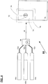
- FIG. 3 the proposed system is shown as a block diagram of the components of the fiber laser welding system 10.
- a fiber laser 20 directs a high density beam 22 in a narrow bandwidth of 1064 nm +/- 0.5 nm.
- the welds are performed with a square temporal shape having a pulse duration of 1.25 milliseconds but other durations may be used of any range as may be required by the welding industry.
- the beam 22 is directed into a welding region 30 having a small fusion zone 26 which allows a weld material 28, such as titanium, to form a weld on a workpiece 24.
- the weld may move as either the workpiece or the laser moves in use, or both.
- An inert argon shielding gas is applied in a cross-flow region 32 (or all components can be placed into glove box with a controlled environment) which serves as a cover gas in the welding region 30 to prevent contamination of the weld.
- Commercial grade argon with purity 99.996% is optimally used.
- the gas shielding flow, orientation, and angle are optimized to obtain a bright, shiny and oxide free surface finish.
- FIG. 4 a proposed system is shown as a block diagram of the components of the fiber laser welding system 50 similar to those in FIG. 3 , but employing one of multiple pulsed fiber lasers 60a, 60b, and 60c via a coupler 64 and coupling paths 62a, 62b, and 62c to direct a high density beam 68 in a narrow bandwidth of 1064 nm +/- 0.5 nm.
- Beam 68 is directed into a welding region 76 having a small fusion zone 72 which allows a weld material 74, such as titanium, to form a weld on a workpiece 70.
- An inert shielding gas preferably argon, is applied in a cross-flow region 78 (or all components can be placed into glove box with a controlled environment) which serves as a cover gas in the welding region 76 to prevent contamination of the weld.
- the flow begins at step 100 with the selection of an air cooled pulse mode fiber laser.
- the laser is 'configured', at step 102, for the task by adjusting for: beam delivery; numerical aperture; spot size; spatial profile; temporal profile; pulse duration; pulse repetition rate; weld spots overlap; weld fixture; and the speed of the weld process, weld material, and cover gas configuration.
- the 'configured' step 102 may be adjusted in symbiosis with the steps of 104, 106, and 108 as will be understood so as to optimize the properties of the system and method. The settings made at this step can be readjusted at subsequent steps as required during a use.
- step 104 a weld material, such as titanium, is placed in position on a workpiece.
- Step 104 can be performed prior to steps 100 and 102; the importance of the step lies in its being performed prior to generation of the laser beam.
- the method flow advances from step 104 to step 106 where a numerical aperture is determined for the beam based on the position of the weld material within the small fusion zone of the workpiece.
- the flow then advances from step 106 to step 108 where a set of 'beam divergence' properties is established to avoid interaction between the wavelength output for the fiber laser's beam and the cover gas or combination of gases, and optionally the non- ferrous alloy to be welded in conjunction with step 102 as shown by the arrow to reach a maximum optimization.
- the embodiments tested included titanium, but others may be used by the system and the method.
- the flow then advances to step 110 where the optimal focus spot size is determined and input to the fiber laser.
- step 112 the fiber laser generates a beam within a narrow bandwidth, here designated as 1064 nm +/- 0.5 nm due to the selected argon cover gas that allows the plasma of the weld to form without the contaminants that are found to form when outside the optimal range.
- the laser beam is then directed, at step 114, into a small fusion zone where the weld material is located on the workpiece.
- the system queries at step 116 as whether or not an inert gas is applied in a cross-flow around the fusion zone.
- an inert gas designated for the system to avoid spectral interference such as argon is applied in a cross-flow across the wok zone at step 116 (or all components can be placed into a controlled environment, e.g. a glove box.
- step 118 the weld is formed on the workpiece.
- the method queries at step 120 as to whether or not another weld is to be performed. If the response to the query is "YES,” then the flow returns to step 104 where the weld material is placed in position for the next weld formation. If, however, the response to the query at step 120 is "NO,” then the flow advances to step 122 where the process is terminated.
- the superior weld was the narrow bandwidth fiber laser at 1064 nm. This avoided additional interactions between the laser beam, the cover gas. and the weld material (titanium). Following the method steps will allow the same benefits for other cover gases and weld materials.
Landscapes
- Physics & Mathematics (AREA)
- Optics & Photonics (AREA)
- Engineering & Computer Science (AREA)
- Plasma & Fusion (AREA)
- Mechanical Engineering (AREA)
- Laser Beam Processing (AREA)
- Lasers (AREA)
- Arc Welding In General (AREA)
Claims (4)
- Verfahren zum Laserstrahlschweißen, wobei das Verfahren die Schritte umfasst: Einrichten eines betriebsfähigen gepulsten Faserlasers (20), der in einer Konfiguration zur Anwendung eines Hochdichtestrahls von Laserlicht in einer schmalen Bandbreite auf einer Verschmelzungszone (26) an einem Schweißmaterial platziert ist, wobei das Schweißmaterial Titan oder Titanlegierung ohne ein Füllmaterial ist; Einrichten von Spektrallinien für ein festgelegtes Schutzgas, wobei das Schutzgas Argon oder Helium ist;
Auswählen eines Emissionsspektrums für den Strahl (22) von Laserlicht; wobei das Emissionsspektrum für den Strahl von Laserlicht die Spektrallinien für das Schutzgas meidet und wobei der Schritt zum Auswählen eines Emissionsspektrums für den Strahl (22) von Laserlicht den Schritt zum Auswählen des Strahls von Laserlicht in einer Bandbreite von 1064 nm +/- 0,5 nm beinhaltet;
Nutzen des Schutzgases um den einen Schweißbereich (30), um Kontaminierung der Schweißnaht zu verhindern; und
Anwenden des Strahls (22) von Laserlicht an dem Schweißmaterial, um eine Schweißnaht in einem Schweißbereich (30) zu bilden. - Verfahren nach Anspruch 1, wobei:der Anwendungsschritt weiter die Schritte umfasst zum: Ermitteln und Beibehalten einer numerischen Apertur für den Hochdichtestrahl (20);Einrichten und Beibehalten eines Satzes von Strahldivergenzmerkmalen; undBerechnen einer optimalen Brennpunktgröße.
- Verfahren nach Anspruch 1, wobei:
die Konfiguration durch Auswählen einer oder mehrerer Eigenschaften aus der Gruppe ermittelt ist, beinhaltend: Strahlführung; numerische Apertur; Punktgröße; räumliches Profil; zeitliches Profil; Pulsdauer; Pulswiederholungsrate; Schweißpunktüberlappung; Schweißbefestigung; und Geschwindigkeit des Schweißens. - Verfahren nach Anspruch 3, wobei:
das Gas Argon ist und die Dicke des Titanschweißmaterials und die Punktgröße für einen visuellen Aspekt der Schweißnaht optimiert wurden.
Applications Claiming Priority (1)
| Application Number | Priority Date | Filing Date | Title |
|---|---|---|---|
| PCT/US2010/050626 WO2012044285A1 (en) | 2010-09-29 | 2010-09-29 | System and method utilizing fiber lasers for titanium welding using an argon cover gas |
Publications (3)
| Publication Number | Publication Date |
|---|---|
| EP2621664A1 EP2621664A1 (de) | 2013-08-07 |
| EP2621664A4 EP2621664A4 (de) | 2017-08-23 |
| EP2621664B1 true EP2621664B1 (de) | 2021-01-27 |
Family
ID=45893464
Family Applications (1)
| Application Number | Title | Priority Date | Filing Date |
|---|---|---|---|
| EP10857979.8A Active EP2621664B1 (de) | 2010-09-29 | 2010-09-29 | System und verfahren unter verwendung von faserlaser für titanschweissen mit einem argonschutzgas |
Country Status (5)
| Country | Link |
|---|---|
| EP (1) | EP2621664B1 (de) |
| JP (1) | JP5798630B2 (de) |
| KR (1) | KR101771101B1 (de) |
| CN (1) | CN102574242B (de) |
| WO (1) | WO2012044285A1 (de) |
Families Citing this family (4)
| Publication number | Priority date | Publication date | Assignee | Title |
|---|---|---|---|---|
| WO2014133013A1 (ja) * | 2013-02-27 | 2014-09-04 | コマツ産機株式会社 | ファイバレーザ加工機の出力制御方法及びファイバレーザ加工機 |
| US20140305910A1 (en) * | 2013-03-27 | 2014-10-16 | Ipg Photonics Corporation | System and Method Utilizing Fiber Lasers for Titanium Welding Using an Argon Cover Gas |
| PL3515651T3 (pl) * | 2016-09-23 | 2024-09-16 | Ipg Photonics Corporation | Analiza przed spawaniem i powiązane sposoby spawania laserowego wykorzystujące wstępnie dobrane szerokości pasm widmowych, które omijają widmo przejścia elektronowego pary metalu/stopu |
| CN116275478B (zh) * | 2023-02-28 | 2025-05-23 | 南京航空航天大学 | 一种光纤-蓝光半导体复合激光焊接能量智能分配装置及方法 |
Family Cites Families (16)
| Publication number | Priority date | Publication date | Assignee | Title |
|---|---|---|---|---|
| KR970033389U (ko) * | 1995-12-28 | 1997-07-26 | 자동차의 후사경 | |
| KR100241032B1 (ko) * | 1995-12-30 | 2000-03-02 | 이구택 | 감마 티타늄 알루미나이드의 용접방법 |
| JPH11245063A (ja) * | 1998-03-02 | 1999-09-14 | Nkk Corp | チタンクラッド鋼板の接合方法 |
| US6525872B1 (en) * | 1999-02-11 | 2003-02-25 | Jds Uniphase Corporation | Fiber grating-stabilized, semiconductor pump source |
| JP3591630B2 (ja) * | 2000-01-20 | 2004-11-24 | 日産自動車株式会社 | レーザ−アーク複合溶接方法および溶接装置 |
| JP3978066B2 (ja) * | 2002-04-08 | 2007-09-19 | 新日本製鐵株式会社 | レーザ加工装置 |
| KR100524253B1 (ko) * | 2003-05-09 | 2005-10-27 | 김효봉 | 첨두 에너지를 가진 펄스 변조형 Nd-YAG 레이저를 이용한 벨로즈 용접 |
| JP4114619B2 (ja) * | 2004-03-01 | 2008-07-09 | 株式会社ジェイテクト | 光ファイバ及びファイバレーザ発振装置 |
| US7718917B2 (en) * | 2005-07-08 | 2010-05-18 | Gm Global Technology Operations, Inc. | Hybrid laser and resistance welding system and method |
| JP4690967B2 (ja) * | 2006-08-21 | 2011-06-01 | 新日本製鐵株式会社 | 加工深さを増加したレーザ加工装置 |
| JP2008055456A (ja) * | 2006-08-30 | 2008-03-13 | Sumitomo Electric Ind Ltd | 半田付け方法および半田付け用レーザ装置 |
| US20080144673A1 (en) * | 2006-12-15 | 2008-06-19 | Ipg Photonics Corporation | Fiber laser with large mode area fiber |
| JP4873482B2 (ja) * | 2007-02-28 | 2012-02-08 | 国立大学法人大阪大学 | 複数のレーザ光源を用いた金属樹脂接合方法及び金属樹脂複合体 |
| JP5385509B2 (ja) * | 2007-04-20 | 2014-01-08 | 新日鐵住金株式会社 | レーザ溶接装置、レーザ溶接方法及び金属板材の製造方法 |
| US7593435B2 (en) * | 2007-10-09 | 2009-09-22 | Ipg Photonics Corporation | Powerful fiber laser system |
| DE112009001685B4 (de) * | 2008-07-09 | 2015-09-03 | Suzuki Motor Corp. | Laserüberlappschweißverfahren |
-
2010
- 2010-09-29 JP JP2013531541A patent/JP5798630B2/ja active Active
- 2010-09-29 WO PCT/US2010/050626 patent/WO2012044285A1/en not_active Ceased
- 2010-09-29 CN CN201080043270.0A patent/CN102574242B/zh active Active
- 2010-09-29 EP EP10857979.8A patent/EP2621664B1/de active Active
- 2010-09-29 KR KR1020127008117A patent/KR101771101B1/ko active Active
Non-Patent Citations (1)
| Title |
|---|
| None * |
Also Published As
| Publication number | Publication date |
|---|---|
| JP2013541420A (ja) | 2013-11-14 |
| EP2621664A1 (de) | 2013-08-07 |
| CN102574242B (zh) | 2015-08-05 |
| EP2621664A4 (de) | 2017-08-23 |
| KR101771101B1 (ko) | 2017-09-05 |
| WO2012044285A1 (en) | 2012-04-05 |
| JP5798630B2 (ja) | 2015-10-21 |
| KR20130133646A (ko) | 2013-12-09 |
| CN102574242A (zh) | 2012-07-11 |
Similar Documents
| Publication | Publication Date | Title |
|---|---|---|
| Katayama | Fundamentals and details of laser welding | |
| US20140305910A1 (en) | System and Method Utilizing Fiber Lasers for Titanium Welding Using an Argon Cover Gas | |
| CN111526966B (zh) | 激光处理装置及方法 | |
| Cao et al. | Research and progress in laser welding of wrought aluminum alloys. I. Laser welding processes | |
| Quintino et al. | Welding with high power fiber lasers–A preliminary study | |
| US8946586B2 (en) | Device and method for laser processing | |
| WO2001005550A1 (en) | Combined laser and plasma-arc processing torch and method | |
| JP2012501855A (ja) | レーザービームのq値を回折光学部材によって変更する手段を用いる、レーザー切断方法および装置 | |
| CN113967787B (zh) | 一种激光焊接方法 | |
| US4689466A (en) | Laser-beam operated machining apparatus | |
| KR101771101B1 (ko) | 아르곤 커버 가스를 사용하여 티타늄 용접하기 위해 광섬유 레이저를 사용하는 시스템 및 방법 | |
| CN109175691A (zh) | 一种镀锌钢的焊接方法 | |
| Ishide et al. | Coaxial TIG‐YAG & MIG‐YAG welding methods | |
| JP2010120023A (ja) | レーザ溶接方法およびレーザ溶接装置 | |
| JP2001166090A (ja) | 原子炉解体方法およびレーザ切断装置 | |
| CN110539076B (zh) | 用于激光焊接的保护气体及应用其的激光焊接方法 | |
| Rath | Lasers for industrial production processing: Tailored tools with increasing flexibility | |
| Kelkar | Pulsed laser welding | |
| US12390882B2 (en) | Pre-welding analysis and associated fiber lasers utilizing pre-selected spectral bandwidths that avoid the spectrum of an electronic transition of a metal/alloy vapor | |
| Webber et al. | Laser beam welding | |
| Timmermann et al. | Intensity increasing up to 4 MW/cm2 with BALB's via wavelengths coupling | |
| Miller et al. | Laser welding of aluminum alloys | |
| JPH09122958A (ja) | アルミニウム合金のパルスレーザ溶接方法 | |
| KR102807317B1 (ko) | 15mm 용접비드폭형 쓰리와이어식 스마트 파이버레이저 용접장치 및 방법 | |
| Wani et al. | High-power COIL and YAG laser welding |
Legal Events
| Date | Code | Title | Description |
|---|---|---|---|
| PUAI | Public reference made under article 153(3) epc to a published international application that has entered the european phase |
Free format text: ORIGINAL CODE: 0009012 |
|
| 17P | Request for examination filed |
Effective date: 20130429 |
|
| AK | Designated contracting states |
Kind code of ref document: A1 Designated state(s): AL AT BE BG CH CY CZ DE DK EE ES FI FR GB GR HR HU IE IS IT LI LT LU LV MC MK MT NL NO PL PT RO SE SI SK SM TR |
|
| DAX | Request for extension of the european patent (deleted) | ||
| RA4 | Supplementary search report drawn up and despatched (corrected) |
Effective date: 20170721 |
|
| RIC1 | Information provided on ipc code assigned before grant |
Ipc: H01S 3/10 20060101ALI20170717BHEP Ipc: B23K 103/14 20060101ALI20170717BHEP Ipc: B23K 26/14 20140101ALI20170717BHEP Ipc: B23K 26/20 20140101AFI20170717BHEP Ipc: H01S 3/067 20060101ALI20170717BHEP |
|
| STAA | Information on the status of an ep patent application or granted ep patent |
Free format text: STATUS: EXAMINATION IS IN PROGRESS |
|
| 17Q | First examination report despatched |
Effective date: 20191219 |
|
| GRAP | Despatch of communication of intention to grant a patent |
Free format text: ORIGINAL CODE: EPIDOSNIGR1 |
|
| STAA | Information on the status of an ep patent application or granted ep patent |
Free format text: STATUS: GRANT OF PATENT IS INTENDED |
|
| INTG | Intention to grant announced |
Effective date: 20200929 |
|
| GRAS | Grant fee paid |
Free format text: ORIGINAL CODE: EPIDOSNIGR3 |
|
| GRAA | (expected) grant |
Free format text: ORIGINAL CODE: 0009210 |
|
| STAA | Information on the status of an ep patent application or granted ep patent |
Free format text: STATUS: THE PATENT HAS BEEN GRANTED |
|
| AK | Designated contracting states |
Kind code of ref document: B1 Designated state(s): AL AT BE BG CH CY CZ DE DK EE ES FI FR GB GR HR HU IE IS IT LI LT LU LV MC MK MT NL NO PL PT RO SE SI SK SM TR |
|
| REG | Reference to a national code |
Ref country code: GB Ref legal event code: FG4D |
|
| REG | Reference to a national code |
Ref country code: CH Ref legal event code: EP |
|
| REG | Reference to a national code |
Ref country code: AT Ref legal event code: REF Ref document number: 1357899 Country of ref document: AT Kind code of ref document: T Effective date: 20210215 |
|
| REG | Reference to a national code |
Ref country code: IE Ref legal event code: FG4D |
|
| REG | Reference to a national code |
Ref country code: DE Ref legal event code: R096 Ref document number: 602010066426 Country of ref document: DE |
|
| REG | Reference to a national code |
Ref country code: CH Ref legal event code: NV Representative=s name: SCHAAD, BALASS, MENZL AND PARTNER AG PATENT- U, CH |
|
| REG | Reference to a national code |
Ref country code: NL Ref legal event code: MP Effective date: 20210127 |
|
| REG | Reference to a national code |
Ref country code: LT Ref legal event code: MG9D |
|
| REG | Reference to a national code |
Ref country code: AT Ref legal event code: MK05 Ref document number: 1357899 Country of ref document: AT Kind code of ref document: T Effective date: 20210127 |
|
| PG25 | Lapsed in a contracting state [announced via postgrant information from national office to epo] |
Ref country code: LT Free format text: LAPSE BECAUSE OF FAILURE TO SUBMIT A TRANSLATION OF THE DESCRIPTION OR TO PAY THE FEE WITHIN THE PRESCRIBED TIME-LIMIT Effective date: 20210127 Ref country code: GR Free format text: LAPSE BECAUSE OF FAILURE TO SUBMIT A TRANSLATION OF THE DESCRIPTION OR TO PAY THE FEE WITHIN THE PRESCRIBED TIME-LIMIT Effective date: 20210428 Ref country code: HR Free format text: LAPSE BECAUSE OF FAILURE TO SUBMIT A TRANSLATION OF THE DESCRIPTION OR TO PAY THE FEE WITHIN THE PRESCRIBED TIME-LIMIT Effective date: 20210127 Ref country code: FI Free format text: LAPSE BECAUSE OF FAILURE TO SUBMIT A TRANSLATION OF THE DESCRIPTION OR TO PAY THE FEE WITHIN THE PRESCRIBED TIME-LIMIT Effective date: 20210127 Ref country code: PT Free format text: LAPSE BECAUSE OF FAILURE TO SUBMIT A TRANSLATION OF THE DESCRIPTION OR TO PAY THE FEE WITHIN THE PRESCRIBED TIME-LIMIT Effective date: 20210527 Ref country code: NO Free format text: LAPSE BECAUSE OF FAILURE TO SUBMIT A TRANSLATION OF THE DESCRIPTION OR TO PAY THE FEE WITHIN THE PRESCRIBED TIME-LIMIT Effective date: 20210427 Ref country code: NL Free format text: LAPSE BECAUSE OF FAILURE TO SUBMIT A TRANSLATION OF THE DESCRIPTION OR TO PAY THE FEE WITHIN THE PRESCRIBED TIME-LIMIT Effective date: 20210127 Ref country code: BG Free format text: LAPSE BECAUSE OF FAILURE TO SUBMIT A TRANSLATION OF THE DESCRIPTION OR TO PAY THE FEE WITHIN THE PRESCRIBED TIME-LIMIT Effective date: 20210427 |
|
| PG25 | Lapsed in a contracting state [announced via postgrant information from national office to epo] |
Ref country code: LV Free format text: LAPSE BECAUSE OF FAILURE TO SUBMIT A TRANSLATION OF THE DESCRIPTION OR TO PAY THE FEE WITHIN THE PRESCRIBED TIME-LIMIT Effective date: 20210127 Ref country code: PL Free format text: LAPSE BECAUSE OF FAILURE TO SUBMIT A TRANSLATION OF THE DESCRIPTION OR TO PAY THE FEE WITHIN THE PRESCRIBED TIME-LIMIT Effective date: 20210127 Ref country code: AT Free format text: LAPSE BECAUSE OF FAILURE TO SUBMIT A TRANSLATION OF THE DESCRIPTION OR TO PAY THE FEE WITHIN THE PRESCRIBED TIME-LIMIT Effective date: 20210127 Ref country code: SE Free format text: LAPSE BECAUSE OF FAILURE TO SUBMIT A TRANSLATION OF THE DESCRIPTION OR TO PAY THE FEE WITHIN THE PRESCRIBED TIME-LIMIT Effective date: 20210127 |
|
| PG25 | Lapsed in a contracting state [announced via postgrant information from national office to epo] |
Ref country code: IS Free format text: LAPSE BECAUSE OF FAILURE TO SUBMIT A TRANSLATION OF THE DESCRIPTION OR TO PAY THE FEE WITHIN THE PRESCRIBED TIME-LIMIT Effective date: 20210527 |
|
| REG | Reference to a national code |
Ref country code: DE Ref legal event code: R097 Ref document number: 602010066426 Country of ref document: DE |
|
| PG25 | Lapsed in a contracting state [announced via postgrant information from national office to epo] |
Ref country code: SM Free format text: LAPSE BECAUSE OF FAILURE TO SUBMIT A TRANSLATION OF THE DESCRIPTION OR TO PAY THE FEE WITHIN THE PRESCRIBED TIME-LIMIT Effective date: 20210127 Ref country code: EE Free format text: LAPSE BECAUSE OF FAILURE TO SUBMIT A TRANSLATION OF THE DESCRIPTION OR TO PAY THE FEE WITHIN THE PRESCRIBED TIME-LIMIT Effective date: 20210127 Ref country code: CZ Free format text: LAPSE BECAUSE OF FAILURE TO SUBMIT A TRANSLATION OF THE DESCRIPTION OR TO PAY THE FEE WITHIN THE PRESCRIBED TIME-LIMIT Effective date: 20210127 |
|
| PG25 | Lapsed in a contracting state [announced via postgrant information from national office to epo] |
Ref country code: ES Free format text: LAPSE BECAUSE OF FAILURE TO SUBMIT A TRANSLATION OF THE DESCRIPTION OR TO PAY THE FEE WITHIN THE PRESCRIBED TIME-LIMIT Effective date: 20210127 Ref country code: DK Free format text: LAPSE BECAUSE OF FAILURE TO SUBMIT A TRANSLATION OF THE DESCRIPTION OR TO PAY THE FEE WITHIN THE PRESCRIBED TIME-LIMIT Effective date: 20210127 Ref country code: SK Free format text: LAPSE BECAUSE OF FAILURE TO SUBMIT A TRANSLATION OF THE DESCRIPTION OR TO PAY THE FEE WITHIN THE PRESCRIBED TIME-LIMIT Effective date: 20210127 Ref country code: RO Free format text: LAPSE BECAUSE OF FAILURE TO SUBMIT A TRANSLATION OF THE DESCRIPTION OR TO PAY THE FEE WITHIN THE PRESCRIBED TIME-LIMIT Effective date: 20210127 |
|
| PLBE | No opposition filed within time limit |
Free format text: ORIGINAL CODE: 0009261 |
|
| STAA | Information on the status of an ep patent application or granted ep patent |
Free format text: STATUS: NO OPPOSITION FILED WITHIN TIME LIMIT |
|
| 26N | No opposition filed |
Effective date: 20211028 |
|
| PG25 | Lapsed in a contracting state [announced via postgrant information from national office to epo] |
Ref country code: AL Free format text: LAPSE BECAUSE OF FAILURE TO SUBMIT A TRANSLATION OF THE DESCRIPTION OR TO PAY THE FEE WITHIN THE PRESCRIBED TIME-LIMIT Effective date: 20210127 |
|
| PG25 | Lapsed in a contracting state [announced via postgrant information from national office to epo] |
Ref country code: SI Free format text: LAPSE BECAUSE OF FAILURE TO SUBMIT A TRANSLATION OF THE DESCRIPTION OR TO PAY THE FEE WITHIN THE PRESCRIBED TIME-LIMIT Effective date: 20210127 |
|
| PG25 | Lapsed in a contracting state [announced via postgrant information from national office to epo] |
Ref country code: IT Free format text: LAPSE BECAUSE OF FAILURE TO SUBMIT A TRANSLATION OF THE DESCRIPTION OR TO PAY THE FEE WITHIN THE PRESCRIBED TIME-LIMIT Effective date: 20210127 |
|
| REG | Reference to a national code |
Ref country code: CH Ref legal event code: PL |
|
| REG | Reference to a national code |
Ref country code: BE Ref legal event code: MM Effective date: 20210930 |
|
| PG25 | Lapsed in a contracting state [announced via postgrant information from national office to epo] |
Ref country code: IS Free format text: LAPSE BECAUSE OF FAILURE TO SUBMIT A TRANSLATION OF THE DESCRIPTION OR TO PAY THE FEE WITHIN THE PRESCRIBED TIME-LIMIT Effective date: 20210527 Ref country code: MC Free format text: LAPSE BECAUSE OF FAILURE TO SUBMIT A TRANSLATION OF THE DESCRIPTION OR TO PAY THE FEE WITHIN THE PRESCRIBED TIME-LIMIT Effective date: 20210127 |
|
| PG25 | Lapsed in a contracting state [announced via postgrant information from national office to epo] |
Ref country code: LU Free format text: LAPSE BECAUSE OF NON-PAYMENT OF DUE FEES Effective date: 20210929 Ref country code: IE Free format text: LAPSE BECAUSE OF NON-PAYMENT OF DUE FEES Effective date: 20210929 Ref country code: FR Free format text: LAPSE BECAUSE OF NON-PAYMENT OF DUE FEES Effective date: 20210930 Ref country code: BE Free format text: LAPSE BECAUSE OF NON-PAYMENT OF DUE FEES Effective date: 20210930 |
|
| PG25 | Lapsed in a contracting state [announced via postgrant information from national office to epo] |
Ref country code: HU Free format text: LAPSE BECAUSE OF FAILURE TO SUBMIT A TRANSLATION OF THE DESCRIPTION OR TO PAY THE FEE WITHIN THE PRESCRIBED TIME-LIMIT; INVALID AB INITIO Effective date: 20100929 Ref country code: CY Free format text: LAPSE BECAUSE OF FAILURE TO SUBMIT A TRANSLATION OF THE DESCRIPTION OR TO PAY THE FEE WITHIN THE PRESCRIBED TIME-LIMIT Effective date: 20210127 |
|
| P01 | Opt-out of the competence of the unified patent court (upc) registered |
Effective date: 20230516 |
|
| PG25 | Lapsed in a contracting state [announced via postgrant information from national office to epo] |
Ref country code: MK Free format text: LAPSE BECAUSE OF FAILURE TO SUBMIT A TRANSLATION OF THE DESCRIPTION OR TO PAY THE FEE WITHIN THE PRESCRIBED TIME-LIMIT Effective date: 20210127 |
|
| PG25 | Lapsed in a contracting state [announced via postgrant information from national office to epo] |
Ref country code: TR Free format text: LAPSE BECAUSE OF FAILURE TO SUBMIT A TRANSLATION OF THE DESCRIPTION OR TO PAY THE FEE WITHIN THE PRESCRIBED TIME-LIMIT Effective date: 20210127 |
|
| PG25 | Lapsed in a contracting state [announced via postgrant information from national office to epo] |
Ref country code: MT Free format text: LAPSE BECAUSE OF FAILURE TO SUBMIT A TRANSLATION OF THE DESCRIPTION OR TO PAY THE FEE WITHIN THE PRESCRIBED TIME-LIMIT Effective date: 20210127 |
|
| REG | Reference to a national code |
Ref country code: CH Ref legal event code: U11 Free format text: ST27 STATUS EVENT CODE: U-0-0-U10-U11 (AS PROVIDED BY THE NATIONAL OFFICE) Effective date: 20251001 |
|
| PGFP | Annual fee paid to national office [announced via postgrant information from national office to epo] |
Ref country code: DE Payment date: 20250820 Year of fee payment: 16 |
|
| PGFP | Annual fee paid to national office [announced via postgrant information from national office to epo] |
Ref country code: GB Payment date: 20250822 Year of fee payment: 16 |
|
| PGFP | Annual fee paid to national office [announced via postgrant information from national office to epo] |
Ref country code: CH Payment date: 20251001 Year of fee payment: 16 |